EP0813351A2 - Sound generator synchronized with image display - Google Patents
Sound generator synchronized with image display Download PDFInfo
- Publication number
- EP0813351A2 EP0813351A2 EP96115144A EP96115144A EP0813351A2 EP 0813351 A2 EP0813351 A2 EP 0813351A2 EP 96115144 A EP96115144 A EP 96115144A EP 96115144 A EP96115144 A EP 96115144A EP 0813351 A2 EP0813351 A2 EP 0813351A2
- Authority
- EP
- European Patent Office
- Prior art keywords
- source data
- sound
- sound source
- storage means
- delay
- Prior art date
- Legal status (The legal status is an assumption and is not a legal conclusion. Google has not performed a legal analysis and makes no representation as to the accuracy of the status listed.)
- Granted
Links
Images


Classifications
-
- A—HUMAN NECESSITIES
- A63—SPORTS; GAMES; AMUSEMENTS
- A63F—CARD, BOARD, OR ROULETTE GAMES; INDOOR GAMES USING SMALL MOVING PLAYING BODIES; VIDEO GAMES; GAMES NOT OTHERWISE PROVIDED FOR
- A63F13/00—Video games, i.e. games using an electronically generated display having two or more dimensions
- A63F13/50—Controlling the output signals based on the game progress
- A63F13/54—Controlling the output signals based on the game progress involving acoustic signals, e.g. for simulating revolutions per minute [RPM] dependent engine sounds in a driving game or reverberation against a virtual wall
-
- A—HUMAN NECESSITIES
- A63—SPORTS; GAMES; AMUSEMENTS
- A63F—CARD, BOARD, OR ROULETTE GAMES; INDOOR GAMES USING SMALL MOVING PLAYING BODIES; VIDEO GAMES; GAMES NOT OTHERWISE PROVIDED FOR
- A63F13/00—Video games, i.e. games using an electronically generated display having two or more dimensions
- A63F13/50—Controlling the output signals based on the game progress
- A63F13/52—Controlling the output signals based on the game progress involving aspects of the displayed game scene
-
- A—HUMAN NECESSITIES
- A63—SPORTS; GAMES; AMUSEMENTS
- A63F—CARD, BOARD, OR ROULETTE GAMES; INDOOR GAMES USING SMALL MOVING PLAYING BODIES; VIDEO GAMES; GAMES NOT OTHERWISE PROVIDED FOR
- A63F13/00—Video games, i.e. games using an electronically generated display having two or more dimensions
- A63F13/40—Processing input control signals of video game devices, e.g. signals generated by the player or derived from the environment
- A63F13/44—Processing input control signals of video game devices, e.g. signals generated by the player or derived from the environment involving timing of operations, e.g. performing an action within a time slot
-
- A—HUMAN NECESSITIES
- A63—SPORTS; GAMES; AMUSEMENTS
- A63F—CARD, BOARD, OR ROULETTE GAMES; INDOOR GAMES USING SMALL MOVING PLAYING BODIES; VIDEO GAMES; GAMES NOT OTHERWISE PROVIDED FOR
- A63F13/00—Video games, i.e. games using an electronically generated display having two or more dimensions
- A63F13/50—Controlling the output signals based on the game progress
- A63F13/52—Controlling the output signals based on the game progress involving aspects of the displayed game scene
- A63F13/525—Changing parameters of virtual cameras
- A63F13/5255—Changing parameters of virtual cameras according to dedicated instructions from a player, e.g. using a secondary joystick to rotate the camera around a player's character
-
- H—ELECTRICITY
- H04—ELECTRIC COMMUNICATION TECHNIQUE
- H04S—STEREOPHONIC SYSTEMS
- H04S1/00—Two-channel systems
-
- A—HUMAN NECESSITIES
- A63—SPORTS; GAMES; AMUSEMENTS
- A63F—CARD, BOARD, OR ROULETTE GAMES; INDOOR GAMES USING SMALL MOVING PLAYING BODIES; VIDEO GAMES; GAMES NOT OTHERWISE PROVIDED FOR
- A63F13/00—Video games, i.e. games using an electronically generated display having two or more dimensions
- A63F13/90—Constructional details or arrangements of video game devices not provided for in groups A63F13/20 or A63F13/25, e.g. housing, wiring, connections or cabinets
- A63F13/95—Storage media specially adapted for storing game information, e.g. video game cartridges
-
- A—HUMAN NECESSITIES
- A63—SPORTS; GAMES; AMUSEMENTS
- A63F—CARD, BOARD, OR ROULETTE GAMES; INDOOR GAMES USING SMALL MOVING PLAYING BODIES; VIDEO GAMES; GAMES NOT OTHERWISE PROVIDED FOR
- A63F2300/00—Features of games using an electronically generated display having two or more dimensions, e.g. on a television screen, showing representations related to the game
- A63F2300/20—Features of games using an electronically generated display having two or more dimensions, e.g. on a television screen, showing representations related to the game characterised by details of the game platform
- A63F2300/206—Game information storage, e.g. cartridges, CD ROM's, DVD's, smart cards
-
- A—HUMAN NECESSITIES
- A63—SPORTS; GAMES; AMUSEMENTS
- A63F—CARD, BOARD, OR ROULETTE GAMES; INDOOR GAMES USING SMALL MOVING PLAYING BODIES; VIDEO GAMES; GAMES NOT OTHERWISE PROVIDED FOR
- A63F2300/00—Features of games using an electronically generated display having two or more dimensions, e.g. on a television screen, showing representations related to the game
- A63F2300/60—Methods for processing data by generating or executing the game program
- A63F2300/6063—Methods for processing data by generating or executing the game program for sound processing
- A63F2300/6081—Methods for processing data by generating or executing the game program for sound processing generating an output signal, e.g. under timing constraints, for spatialization
-
- A—HUMAN NECESSITIES
- A63—SPORTS; GAMES; AMUSEMENTS
- A63F—CARD, BOARD, OR ROULETTE GAMES; INDOOR GAMES USING SMALL MOVING PLAYING BODIES; VIDEO GAMES; GAMES NOT OTHERWISE PROVIDED FOR
- A63F2300/00—Features of games using an electronically generated display having two or more dimensions, e.g. on a television screen, showing representations related to the game
- A63F2300/60—Methods for processing data by generating or executing the game program
- A63F2300/63—Methods for processing data by generating or executing the game program for controlling the execution of the game in time
-
- A—HUMAN NECESSITIES
- A63—SPORTS; GAMES; AMUSEMENTS
- A63F—CARD, BOARD, OR ROULETTE GAMES; INDOOR GAMES USING SMALL MOVING PLAYING BODIES; VIDEO GAMES; GAMES NOT OTHERWISE PROVIDED FOR
- A63F2300/00—Features of games using an electronically generated display having two or more dimensions, e.g. on a television screen, showing representations related to the game
- A63F2300/60—Methods for processing data by generating or executing the game program
- A63F2300/64—Methods for processing data by generating or executing the game program for computing dynamical parameters of game objects, e.g. motion determination or computation of frictional forces for a virtual car
-
- A—HUMAN NECESSITIES
- A63—SPORTS; GAMES; AMUSEMENTS
- A63F—CARD, BOARD, OR ROULETTE GAMES; INDOOR GAMES USING SMALL MOVING PLAYING BODIES; VIDEO GAMES; GAMES NOT OTHERWISE PROVIDED FOR
- A63F2300/00—Features of games using an electronically generated display having two or more dimensions, e.g. on a television screen, showing representations related to the game
- A63F2300/60—Methods for processing data by generating or executing the game program
- A63F2300/66—Methods for processing data by generating or executing the game program for rendering three dimensional images
- A63F2300/6661—Methods for processing data by generating or executing the game program for rendering three dimensional images for changing the position of the virtual camera
- A63F2300/6676—Methods for processing data by generating or executing the game program for rendering three dimensional images for changing the position of the virtual camera by dedicated player input
Definitions
- the present invention relates generally to a sound generator synchronized with image display, and more particularly, to a sound generator for generating sounds such as a sound effect or music having a three-dimensional extent on the basis of the direction, the distance, and the like between two objects displayed in an image processor such as a personal computer or a video game set.
- a technique for generating stereo sounds As a technique for generating stereo sounds, a technique disclosed in Japanese Patent Publication No. 9397/1985 (prior art 1) has been conventionally known.
- the prior art 1 is for outputting one audio signal as an analog signal as it is and outputting the audio signal as a delayed analog signal, to produce stereo sounds.
- the prior art 1 cannot be applied to a digital sound source because the analog signal is delayed. Moreover, in the prior art 1, the moving state of an object or a character displayed on a screen of a CRT display or the like is not considered, whereby such sounds as to be synchronized with the movement of the object cannot be generated.
- a sound generator for generating two-dimensional sounds in relation to image display As a sound generator for generating two-dimensional sounds in relation to image display, a sound generator disclosed in Japanese Patent Laid-Open No. 155879/1987 (prior art 2) has been known.
- the prior art 2 is for controlling the sound volumes from left and right speakers as an airplane which is a moving object to be a sound source in a two-dimensional manner by gradually decreasing the sound volume from the speaker from which the airplane moves farther apart and gradually increasing the sound volume of the speaker to which the airplane moves closer.
- the sound volume is only gradually decreased or increased as the moving object moves. Even if the sounds are heard as stereo sounds, therefore, tree-dimensional sound effects are not obtained. Further, a sound effect obtained by the prior art 2 is not suitable as a sound effect for a three-dimensional image display. The reason for this is that sound effects are obtained if sounds are generated in synchronization with the movement of a moving object which moves in a two-dimensional manner, for example, an airplane or an automobile, while three-dimensional sound effects cannot be obtained when a three-dimensional image is displayed, whereby the image display and the sound effects (or the presence) do not coincide with each other, producing an uncomfortable impression on a user.
- the sounds generated from the speakers are heard by the user while extending in every direction, whereby a slight time delay occurs between the sound generated from one of the right and left speakers and transmitted to the left or right ear of the user and the sound generated from the other speaker and transmitted to the right or left ear of the user, so that sound effects similar to those in delaying one of the sounds are slightly produced, while three-dimensional sound effects have not been obtained yet.
- an object of the present invention is to provide a sound generator capable of generating three-dimensional sounds which are changed as a camera is moved in a case where a three-dimensional image as viewed from the camera is displayed.
- Another object of the present invention is to provide a sound generator capable of reducing the fatigue of a user even when the user hears sounds using a headphone.
- the present invention has the following characteristics.
- the present invention is directed to a sound generator for generating, in an image display device for displaying a three-dimensional image, sounds having a spatial extent corresponding to the three-dimensional image, which comprises a first sound generation section for generating a first sound, a second sound generation section for generating a second sound, a sound source data storage section for digitally storing sound source data, a temporary storage section for temporarily storing the sound source data read out from the sound source data storage section, a delay time calculation section for calculating, when the image display device displays a first display object so defined as to generate sounds, delay time on the basis of a direction to the first display object as viewed from the position of a predetermined viewpoint, a audio processing section for reading out the sound source data corresponding to the first display object from the sound source data storage section for each unit time, storing the sound source data in the temporary storage section and reading out the sound source data as a first sound source data, and reading out the sound source data stored in the temporary storage section as a second sound source data at timing delayed by the delay time calculated by
- the delay time between the first sound source data and the second sound source data is changed depending on the change of the direction to the first display object as viewed from the position of the predetermined viewpoint, whereby the sounds having a spatial extent corresponding to the change of the three-dimensional image can be generated from the first and second sound source generation sections. Since image display and sound effects coincide with each other in the present invention, therefore, a user can be made to feel image and sound effects closer to reality, whereby the interest of the user can be further improved. Further, when the user hears the sounds generated from the sound generator according to the present invention using a headphone stereo, the fatigue of the user can be reduced.
- Fig. 1 is a block diagram showing the construction of a sound generator according to a first embodiment of the present invention.
- an image/audio processor (hereinafter referred to as a "processor") 10 is, for example, a video game set for generating images and sounds such as music and a sound effect for a game, and comprises an image processing unit 11 and a audio processing unit 12.
- An image memory 13 is connected to the image processing unit 11 through an address bus and a data bus. Further, an external memory 20 and an controller 30 are detachably connected to the image processing unit 11.
- the image processing unit 11 performs an operation for image processing on the basis of data representing the operating state inputted from the controller 30, and image data and program data which are stored in an image data/program data memory 21 in the external memory 20, and feeds image display data generated by the operation to an image signal generation circuit 14.
- the image processing unit 11 generates image display data for displaying one or a plurality of objects which generate sounds such as music and/or a sound effect of the game on the basis of programs (for example, a waterfall, a river, an animal, an automobile, an airplane, or the like) and an object which does not generate sounds (for example, a building, a plant, a road, a cloud, a scene, or the like) in a three-dimensional manner as the line of sight of a camera is moved.
- the camera is a virtual camera which is not displayed on a screen of a display device. An image projected on the virtual camera is displayed on the screen of the display device. Further, the line of sight of the camera is moved by the progress of the game, the operation of a player, and the like.
- the line of sight of the camera may, in some cases, be moved in synchronization with the movement of the line of sight of the hero character.
- the image signal generation circuit 14 generates an image signal with various synchronizing signals required to display an image by a CRT (Cathode Ray Cube) or a standard television receiver (hereinafter referred to as a "television") 40 which is one example of the display device on the basis of the image display data fed from the image processing unit 11, and feeds the image signal to the television 40, to display an image on a display screen (or a display section) 41.
- a CRT Cathode Ray Cube
- a standard television receiver hereinafter referred to as a "television” 40 which is one example of the display device on the basis of the image display data fed from the image processing unit 11, and feeds the image signal to the television 40, to display an image on a display screen (or a display section) 41.
- the image processing nit 11 feeds to the audio processing unit 12 coordinate data (hereinafter referred to as "first coordinate data") of an object which generates sounds (hereinafter referred to as a “sound generating object”) out of various display objects, coordinate data (hereinafter referred to as “second coordinate data") of the virtual camera (or the hero character), and data for designating the type of sound for the purpose of changing a sound effect such as the sound of water such as a waterfall or a river, the sound in running of an automobile, or the cry of an animal as the line of sight of the virtual camera is moved, that is, for the purpose of obtaining three-dimensional sound effects in synchronization with three-dimensional image display.
- the coordinate data fed to the audio processing unit 12 also includes Z coordinate data representing the depth direction in addition to X coordinate data representing the transverse direction of the screen and Y coordinate data representing the longitudinal direction of the screen.
- a sound source data memory 22 included in the external memory 20 is detachably connected to the audio processing unit 12, and a buffer memory for audio processing (hereinafter referred to as a "buffer memory”) 15 for temporarily storing sound source data is connected thereto through a data bus and an address bus.
- buffer memory for audio processing
- the sound source data memory 22 stores a large amount of sound source data used for one game executed by programs in the external memory 20 in the form of PCM data or AD-PCM data.
- the buffer memory 15 includes a buffer area 15a and a delay buffer area 15b (see Fig. 9 showing the embodiment as described in detail later).
- the buffer area 15a temporarily stores audio data in order to generate a first audio signal which are not delayed in given unit time, which is hereinafter referred to as a non-delay buffer area.
- the delay buffer area 15b has a storage capacity corresponding to maximum delay time in order to generate a second audio signal which are delayed from the first audio signal by time corresponding to delay time operated on the basis of the distance and the direction between the coordinates of the sound generating object and the coordinates of the virtual camera (or the hero character).
- the storage capacity of the delay buffer area 15b is selected as a storage capacity which is one-fifth of that of the non-delay buffer area 15a.
- the non-delay buffer area 15a has 320 bytes as a storage capacity corresponding to the unit time
- the delay buffer area 15b has 64 bytes as a storage capacity corresponding to the maximum delay time.
- the unit processing time is determined by the relationship between a sampling frequency in a case where audio signals are sampled to produce audio data (for example, 32 KHz) and time corresponding to audio signals to be processed at one time (that is, time corresponding to the processing unit), and is set to 1/200 to 1/240 seconds in the present embodiment.
- the delay time of the second audio signal from the first audio signal is variably controlled depending on a direction to the sound generating object as viewed from the camera (or the hero character) or an amount of change between directions to the sound generating object as viewed from the camera in a case where the camera (or the hero character) is moved before and after the movement (or angles based on the directions).
- a start address to which a second sound source data is to be written may be variably controlled in the range of 0 to 64 bytes depending on the delay time using a delay buffer area 15b' having a storage capacity which is the sum of the storage capacity of the non-delay buffer area 15a and the storage capacity of the delay buffer area 15b in place of the delay buffer area 15b (see Fig. 10 showing the embodiment as described in detail later).
- the audio processing unit 12 executes operation processing on the basis of predetermined programs in accordance with the first and second coordinate data, finds a direction (or an angle) to the sound generating object as viewed from the camera (or the hero character), and determines on the basis of the direction an amount of delay (or delay time) so as to have a relationship shown in a characteristic view of Fig. 6 as described later.
- the audio processing unit 12 finds the distance between the sound generating object and the camera (or the hero character) on the basis of the first and second coordinate data, and determines the sound volume on the basis of data representing the distance.
- the audio processing unit 12 reads out audio data corresponding to the processing unit (320 bytes) out of the audio data stored in the sound source data memory 22 in a predetermined period and writes the audio data into the non-delay buffer area 15a, finds an amount of change (an angle) between directions to the sound generating object as viewed from the camera (or the hero character) on the basis of coordinate data respectively representing the position of the camera (or the hero character) and the positions of the sound generating object before and after the processing unit time, and finds delay time corresponding to the amount of change between the directions by operation processing.
- the delay time may be determined by previously setting data representing delay time in a table for each angle based on a direction and reading out corresponding data representing delay time from the table in place of the operation processing.
- a write area of the delay buffer area 15b is determined depending on the delay time thus determined.
- the audio processing unit 12 reads out the sound source data stored in the non-delay buffer area 15a and outputs the sound source data as a first sound source data, writes the first sound source data into addresses of the delay buffer area 15b corresponding to the delay time, and reads out the sound source data from the final address of the delay buffer area 15b and outputs the sound source data as a second sound source data which is delayed from the first sound source data by desired delay time.
- the first audio signal and the second audio signal do not respectively fixedly correspond to left and right speakers (or left and right sound generating bodies of a headphone).
- the first audio signal corresponds to a channel of audio signals which are not delayed
- the second audio signal correspond to a channel of audio signals which are delayed.
- the audio processing unit 12 feeds the first audio data to a digital-to-analog conversion circuit for left 16a and feeds the second audio data to a digital-to-analog conversion circuit for right 16b when it judges that the sound generating object exists on the left side of the front of the camera (or the hero character).
- the audio processing unit 12 feeds the first audio data to the digital-to-analog conversion circuit for right 16b and feeds the second audio data to the digital-to-analog conversion circuit for left 16a when it judges that the sound generating object exists on the right side of the front of the camera (or the hero character). Specifically, the audio processing unit 12 switches a combination of the digital-to-analog conversion circuits 16a and 16b (or 16b and 16a) for feeding the first and second audio data for each unit time depending on whether the sound generating object exists on the right side or the left side as viewed from the camera (or the hero character).
- the digital-to-analog conversion circuits 16a and 16b subject the inputted audio data to digital-to-analog conversion, to generate audio signals, and feed the audio signals to corresponding filters 17a and 17b.
- the filters 17a and 17b respectively subject the left and right audio signals to interpolation processing, to waveform-shape the audio signals into smooth audio signals, and feed the wave-shaped audio signals to left and right speakers 42L and 42R provided in relation to the television 40 and/or feed the audio signals to a headphone 44 through an earphone jack 43, thereby to generate sounds.
- the audio processing unit 12 further includes a sound volume control section 12a.
- the sound volume control section 12a finds the distance between the sound generating object and the camera (or the hero character), and controls the sound volume depending on the found distance. For example, the sound volume control section 12 controls the sound volume so that the sound volume is increased if the camera (or the hero character) approaches the sound generating object to decrease the distance therebetween, while being decreased if the camera (or the hero character) moves farther apart from the sound generating object to increase the distance therebetween.
- the sound volume is so controlled as to be inversely proportional to the square of the distance between the camera (or the hero character) and the sound generating object, it is possible to change the presence of a sound effect in correspondence to the change in three-dimensional image display with the movement of the camera (or the hero character).
- the above-mentioned operations are repeatedly performed for each unit time, whereby a sound effect for a game or BGM music (game music) for raising the atmosphere of the game is generated in synchronization with the change of an image.
- the audio processing unit 12 controls a difference between timing at which the first audio data is outputted and timing at which the second audio data is outputted (an amount of delay of one of the audio data from the other audio data) on the basis of a direction or an angle to the sound generating object as viewed from the camera (or the hero character), and controls the sound volume on the basis of the distance between the position of the camera (or the hero character) and the position of the sound generating object.
- audios or sounds heard from the left and right speakers 42L and 42R or the headphone 44 are also changed in a three-dimensional manner in synchronization with the change in three-dimensional image display corresponding to the movement of the line of sight to the sound generating object as viewed from the camera (or the hero character).
- the sound volume may be controlled not in the maximum range from the minimum sound volume to the maximum sound volume but in a range obtained by restricting or suppressing the maximum range.
- a sound insulating object for insulating sounds for example, a building such as a house or a wall, or a large moving object such as a ship or an airplane
- sound effects further conforming to reality are obtained if the sound volume control section 12a so controls the sound volume that its level becomes extremely lower.
- a mode in which the sound volume is controlled depending on the distance between sound generating objects in a case where there is an amount of delay (see Fig. 5), and a mode in which the amount of delay is controlled by the positional relationship (the direction) between the sound generating object and the camera (or the hero character) (see Fig. 6) are executed individually or in a suitable combination on the basis of the programs.
- a specific method for realizing control of the sound volume and/or control of the amount of delay as shown in the characteristic views of Figs. 3 to 6 may be a method of changing the relationship between the distance/direction and the sound volume into an equation so as to be a characteristic waveform shown in Figs. 3 to 6 and storing the equation, operating the distance/direction and/or the sound volume using the stored equation for each control, or setting a sound volume value of the waveform in a table for each left and right unit distance centered around the position of the camera (or the hero character) and reading out the sound volume value considering data representing the distance as an address.
- the sound volume of the left audio signal is set to the maximum amount of change and the sound volume of the right audio signal is set to zero when the sound generating object exists on the left side (at an angle of 0 ) as viewed from the camera (or the hero character) (see Fig. 3).
- the sound volume of the right audio signal is gradually increased and the sound volume of the left audio signal is gradually decreased, as indicated by the characteristic view of Fig. 3.
- the sound volumes of the left and right audio signals are made equal to each other.
- the sound volume of the left audio signal is set to zero and the sound volume of the right audio signal is set to the maximum amount of change.
- the sound volumes of the left and right audio signals may be similarly controlled.
- the increase or decrease of the sound volumes is controlled by multiplexing the change in characteristics shown in Fig. 3 by a correction value so that the sound volumes are inversely proportional to a value obtained by multiplying by a given coefficient the distance between the sound generating object and the camera (or the hero character).
- a game scene where the sound volume is controlled combined with three-dimensional display, that is, a game scene where the sound volume is controlled in relation to amounts of delay of the left and right audio signals
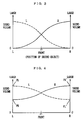
- the sound volume of the left audio signal is set to the maximum amount of change and the sound volume of the right audio signal is set to approximately one-half of the maximum amount of change (see Fig. 4).
- the reason why the minimum sound volume is set to not zero but one-half of the maximum sound volume (or the maximum amount of change) in a case where there is a delay is that three-dimensional sound effects are obtained even if the sound volumes of the left and right audio signals are not made different from each other in the maximum range by delaying the left and right audio signals.
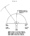
- the sound volume of the right audio signal is gradually increased and the sound volume of the left audio signal is gradually decreased, as shown in Fig. 4, as the sound generating object is so moved rightward as to draw a semicircle spaced apart by a predetermined distance r around the camera (or the hero character) as shown in Fig. 2.
- the sound volumes of the left and right audio signals are made equal to each other. Further, when the sound generating object is moved rightward to reach a position on the right side of the camera (or the hero character), the sound volume of the right audio signal is set to the maximum amount of change and the sound volume of the left audio signal is set to one-half of the maximum amount of change.
- the sound volumes of the left and right audio signals take values intermediate between the maximum amount of change and the minimum amount of change.
- the sound volume is so changed as to be exponentially decreased.
- the sound volume is set to zero.
- Figs. 2 and 6 description is made of the mode in which the amount of delay is controlled in relation to the positional relationship between the sound generating object and the camera (or the hero character).
- the camera or the hero character
- the sound generating object exists at the front, it is necessary that there is no amount of delay between the left audio signal and the right audio signal. If the amount of delay is so controlled as to be changed even when the camera (or the hero character) is only slightly moved leftward or rightward, an uncomfortable impression is given in relation to image display.
- the amount of delay is so controlled as not to be changed in the range of predetermined distances on the left and right sides from the camera (or the hero character).
- the amount of delay of the left audio signal is set to zero and the amount of delay of the right audio signal is set to the maximum amount of delay.
- the amount of delay of the right audio signal is decreased as the sound generating object is so moved rightward as to draw a semicircle spaced apart by a predetermined distance r around the camera (or the hero character), the amounts of delay of the left and right audio signals are set to zero in the range of predetermined distances on the left and right sides from the center, and the amount of delay of the left audio signal is gradually increased with the amount of delay of the right audio signal set to zero as the sound generating object is moved rightward from a position spaced apart from the center by a predetermined distance.
- Fig. 7 is a block diagram showing the construction of a sound generator according to a second embodiment of the present invention.
- the sound generator according to the present embodiment differs from the sound generator according to the first embodiment (see Fig. 1) in the following points.
- the main body of the processor 10 is replaced with a video game set 50.
- the image processing unit 11 is constituted by a main CPU (M-CPU) 51 and two risk CPUs (R-CPUs) 52 and 53.
- the image memory 13 and the buffer memory 15 are constituted by a working RAM (W-RAM) 55 having a large storage capacity.
- the audio processing unit 12 is constituted by one R-CPU 53. That is, the R-CPU 53 is used for both image processing and audio processing.
- the image processing unit 11 is constituted by the three CPUs (the M-CPU 51, the R-CPU 52, and the R-CPU 53).
- the reason why the audio processing unit 12 is constituted by one R-CPU 53 is that the audio processing can be performed in a shorter time period than the image processing.
- the reason why the image memory 13 and the buffer memory 15 are constituted by one W-RAM 55 having a large capacity (for example, 4 megabytes) is that the degree of freedom of the assignment of a memory space is increased so that the distribution of time periods used for the image processing and the audio processing can be set flexibly depending on the purpose of use.
- a controller control circuit 56 In order to control input/output of a plurality of conrtollers 30, a controller control circuit 56 is provided. Further, an input/output control circuit (I/O) 57 is provided in order to control data transfer or input/output between the M-CPU 51, the R-CPU 52, the R-CPU 53 and the W-RAM 55 and an external memory 20, the controller control circuit 56 and the like.
- I/O input/output control circuit
- a connector for a cartridge 581 is provided in order to detachably mount the external memory 20
- connectors for a controller 582 and 583 are provided in order to detachably connect the controllers 30 to the controller control circuit 56
- connectors for audio 584 and 585 are provided in order to connect filters 17a and 17b to speakers 42L and 42R or a headphone 44 of a television 40
- a connector for an image signal 586 is provided in order to connect an image signal generation circuit 14 to a display 41.
- the various types of connectors 581 to 586 are merely referred to as "connectors". Since the other construction is the same as that shown in Fig. 1 and hence, the same sections are assigned the same reference numerals, and the detailed description thereof is omitted.
- the ROM cartridge may be replaced with various recording or storage media such as a CD-ROM optically storing data, a magnetic disk magnetically storing data, and a magneto-optic disk.
- a recording or reproducing device corresponding to the type of information storage medium must be provided to read out a certain amount of data from the information storage medium and temporarily store the data in a memory space in a part of the W-RAM 55 in the video game set 50.
- Fig. 8 is a diagram illustrating the memory space of the W-RAM 55.
- the W-RAM 55 includes a program area 55a to and in which parts of the programs stored in the image/program memory 21 are transferred and stored, a frame memory area 55b storing image data corresponding to one frame (corresponding to an image frame), a Z buffer area 55c storing depth coordinate data for each object or character, an image data area 55d, a sound memory area 15 for audio data processing, a control pad data storage area 55e, and a working memory area 55f.
- the sound memory area 15 corresponds to the buffer memory shown in Fig. 1, and includes a non-delay buffer area 15a, a delay buffer area 15b, and an object coordinate data storage area 15c, as illustrated in Fig. 8.
- the non-delay buffer area 15a and the delay buffer area 15b have memory structures as specifically shown in Fig. 9, and data are written/read out as shown. Specifically, when audio data for each processing unit are written to/read out of the non-delay buffer area 15a, data previously written are shifted to the succeeding address one byte at a time every time audio data composed of one byte are written to the first address.
- audio data are written in a first-in first-out manner, and are read out and outputted as audio data (read data) on a first channel (CH1) from the final address.
- the audio data on the first channel read out from the non-delay buffer area 15a are written as they are to the first address of the delay buffer area 15b.
- audio data at an address designated by an address register (an internal register included in the R-CPU 53) 15d storing a read address of the delay buffer area 15b are read out and outputted as audio data on a second channel (CH2).
- the number of addresses (bytes) from the first address of the delay buffer area 15b to the read address designated by the address register 15d becomes delay time of sounds on the second channel from sounds on the first channel.
- a capacity corresponding to the maximum delay time is sufficient as the storage capacity of the delay buffer area 15b.
- a read control program in the R-CPU 53 becomes complicated.
- the read address designated by the address register 15d may be set to the same first address as a write address of the delay buffer area 15b. Therefore, the delay time can be changed in a wide range.
- a memory structure as shown in Fig. 10 may be used if a sound memory area 15 having a large storage capacity can be prepared.
- a value of a write address corresponding to delay time is written into an address register 15e contained in the R-CPU 53 by the R-CPU 53.
- the same audio data as those on the first channel are simultaneously written at addresses designated by the address register 15e.
- the audio data are read out from the delay buffer area 15b' (sounds on the second channel are generated), starting at the final address of the delay buffer area 15b'. Consequently, timing at which the audio data on the second channel are read out is delayed from timing at which the same audio data on the first channel are read out (sounds on the first channel are generated) by a time period proportional to the number of addresses obtained by subtracting the value of the address in the address register 15e from the number of addresses corresponding to the delay buffer area 15b.
- the coordinate data storage area 15c is an area storing coordinate data of an sound generating object or the like which is displayed on a screen.
- the coordinate data storage area 15c sotres coordinate data of an object 1 generating sounds such as an enemy character or a waterfall as coordinate data of the object 1.
- the coordinate data storage area 15c stores coordinate data of an object 2 such as a camera (or a hero character) whose line of sight is moved to see the object 1 by an operator operating the controllers 30 as coordinate data of the object 2.
- the M-CPU 51 calculates a direction to the object 1 as viewed from the object 2 and the distance therebetween on the basis of the coordinate data of the object 1 and the coordinate data of the object 2.
- a program previously so set as to produce three-dimensional sound effects most suitable for three-dimensional image display out of the characteristic views of Figs. 3 to 6 is executed on the basis of data representing the direction and the distance, to generate data representing the delay time, the sound volume and the type of sound, and feed to the R-CPU 53 the data representing the delay time, the sound volume and the type of sound.
- the R-CPU 53 carries out writing/reading control described while referring to Fig. 9 or 10, to control the delay time of the sounds generated from each of the first channel and the second channel and control the sound volume thereof.
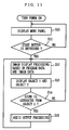
- step S10 a menu panel for initialization of the game is displayed.
- step S11 the M-CPU 51 judges whether or not a decision button (for example, a start button) of the controller 30 is depressed.
- a decision button for example, a start button
- the program proceeds to the step S12.
- step S10 the program is returned to the step S10.
- the M-CPU 51, the R-CPU 52 and the R-CPU 53 perform image display processing for the progress of the game on the basis of program data and image data which are stored in the external memory 20.
- an object 1 which is, for example, an enemy character generating sounds and an object 2 which is a hero character operated as an operator are displayed on the display 41 as one scene on a game screen.
- step S15 processing for audio output (processing in a subroutine described in detail while referring to Fig. 12 as described later) is performed.
- step S14 when it is judged that the condition that the object 1 should generate sounds is not satisfied, the program is returned to the step S12.
- step S12 image display processing corresponding to the progress of the game is continued.
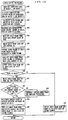
- the M-CPU 51 reads out the coordinate data of the object 1 and the coordinate data of the object 2 on the basis of the coordinate data storage area 15c stored in the sound memory area 15 shown in Fig. 8.
- the direction to the object 1 as viewed from the object 2 and the distance therebetween are then calculated on the basis of the coordinate data of the object 1 and the coordinate data of the object 2.
- the step S22 as described while referring to Figs. 3 to 6, the amount of delay is calculated on the basis of the direction in which the object 1 exists, and the sound volume is calculated on the basis of the direction and the distance.
- step S23 data representing the sound volume and the amount of delay which are found by the calculation and data representing the type of sound are then transferred to the R-CPU 53.
- the R-CPU 53 then reads out a audio frame (audio data for each processing unit) from the sound source data memory 22 in the external memory 20 on the basis of the data representing the type of sound.
- the audio frame read out from the sound source data memory 22 is then written into the non-delay buffer area 15a shown in Fig. 9.
- the sound volume of the audio frame is then controlled on the basis of the data representing the sound volume. Specifically, the sound volume is separately controlled on the left and right sides in correspondence to the direction of the object 1 as indicated by L and R in Fig.
- step S27 data of the audio frame whose sound volume is controlled is then read out from the final address of the non-delay buffer area 15a.
- step S28 the audio frame read out is then outputted as audio data on a first channel.
- step S29 the R-CPU 53 then judges whether or not there is a delay on the basis of the data representing the amount of delay. When it is judged that there is no delay, the program proceeds to the step S30.
- step S30 the R-CPU 53 outputs the audio frame read out from the non-delay buffer area 15a as audio data on a second channel.
- the program proceeds to the step S31.
- the R-CPU 53 writes the audio frame read out from the non-delay buffer area 15a into the delay buffer area 15b.
- the R-CPU 53 judges whether or not the previous amount of delay is the same as the current amount of delay.
- the program proceeds to the step S33.
- the R-CPU 53 performs re-sampling processing of the audio frame. Specifically, when the current amount of delay is smaller than the previous amount of delay, the R-CPU 53 compresses the audio frame by the amount of change in the amount of delay.
- the R-CPU 53 expands the audio frame by the amount of change in the amount of delay.
- the re-sampling processing of the audio frame is then performed, after which the program proceeds to the step S34.
- the program proceeds to the step S34. Further, when the current amount of delay corresponds to the amount of delay at the time of starting sound generation, the current amount of delay cannot be compared with the previous amount of delay, whereby the program proceeds to the step S34 considering that they are the same.
- the R-CPU 53 designates a value of an address in the address register 15d on the basis of the amount of delay. In the step S35, the R-CPU 53 then reads out the audio frame written into the delay buffer area 15b from the designated address, and outputs the audio frame as audio data on the second channel.
- step S29 when it is judged that there is no amount of delay, audio data are outputted as shown in the timing chart of Fig. 13.
- the length of time of audio data for each processing unit is set to 1/240 seconds (approximately 4 ms), for example.
- delay processing need not be performed by the first channel and the second channel, whereby the R-CPU 53 simultaneously outputs the audio frame 1 to the first channel and the second channel. This is also repeated with respect to data corresponding to the audio frame 2 and the subsequent data.
- the audio data are outputted as in the timing chart of Fig. 14.
- a time period corresponding to the amount of delay is variably controlled in the range of 0 to 1/1000 seconds (1 ms), and the second channel has a constant amount of delay of 1/2000 seconds (0.5 ms).
- the R-CPU 53 When the sound generation is started, the R-CPU 53 outputs the audio frame 1 on the side of the second channel after a delay of 0.5 ms from the audio frame 1 on the side of the first channel in order to form a portion where there is no sound for only a time period corresponding to the amount of delay on the side of the second channel.
- a portion, which corresponds to 0.5 ms, of the audio frame 1 remains on the side of the second channel.
- the portion, which corresponds to the remaining 0.5 ms, of the audio frame 1 is outputted on the side of the second channel, after which the second frame 2 is outputted.
- audio data are outputted as shown in the timing chart of Fig. 15.
- the audio frame 1 and the audio frame 2 on the side of the first channel are outputted, the audio frame 1 and the audio frame 2 on the side of the second channel are respectively outputted after delays of 0.5 ms and 0.25 ms (that is, the amount of delay is changed from 0.5 ms to 0.25 ms).
- the amount of change in the amount of delay at this time is decreased by 0.25 ms.
- the R-CPU 53 compresses the audio frame 1 on the side of the second channel by 0.25 ms corresponding to the amount of change in the amount of delay (that is, the audio frame 1 is re-sampled from 4 ms to 3.75 ms).
- the audio frame 2 on the side of the first channel is outputted, a portion, which corresponds to 0.25 ms, of the audio frame 1 remains on the side of the second channel, whereby it is possible to achieve the change in the amount of delay from 0.5 ms to 0.25 ms.
- the amount of delay on the side of the second channel is changed to 0.75 ms, whereby the R-CPU 53 expands the audio frame 2 on the side of the second channel by 0.5 ms corresponding to the amount of change in the amount of delay (that is, the audio frame 2 is re-sampled from 4 ms to 4.5 ms).
- the audio frame 3 on the side of the first channel is outputted, a portion, which corresponds to 0.75 ms, of the audio frame 2 remains on the side of the second channel, whereby it is possible to achieve the change in the amount of delay from 0.25 ms to 0.75 ms.
- the audio output processing in a case where the amount of delay is variable can be achieved by re-sampling processing of the audio frame from (n) to (n + df - db).
Abstract
Description
- The present invention relates generally to a sound generator synchronized with image display, and more particularly, to a sound generator for generating sounds such as a sound effect or music having a three-dimensional extent on the basis of the direction, the distance, and the like between two objects displayed in an image processor such as a personal computer or a video game set.
- As a technique for generating stereo sounds, a technique disclosed in Japanese Patent Publication No. 9397/1985 (prior art 1) has been conventionally known. The
prior art 1 is for outputting one audio signal as an analog signal as it is and outputting the audio signal as a delayed analog signal, to produce stereo sounds. - However, the
prior art 1 cannot be applied to a digital sound source because the analog signal is delayed. Moreover, in theprior art 1, the moving state of an object or a character displayed on a screen of a CRT display or the like is not considered, whereby such sounds as to be synchronized with the movement of the object cannot be generated. - As a sound generator for generating two-dimensional sounds in relation to image display, a sound generator disclosed in Japanese Patent Laid-Open No. 155879/1987 (prior art 2) has been known. The
prior art 2 is for controlling the sound volumes from left and right speakers as an airplane which is a moving object to be a sound source in a two-dimensional manner by gradually decreasing the sound volume from the speaker from which the airplane moves farther apart and gradually increasing the sound volume of the speaker to which the airplane moves closer. - In the
prior art 2, however, the sound volume is only gradually decreased or increased as the moving object moves. Even if the sounds are heard as stereo sounds, therefore, tree-dimensional sound effects are not obtained. Further, a sound effect obtained by theprior art 2 is not suitable as a sound effect for a three-dimensional image display. The reason for this is that sound effects are obtained if sounds are generated in synchronization with the movement of a moving object which moves in a two-dimensional manner, for example, an airplane or an automobile, while three-dimensional sound effects cannot be obtained when a three-dimensional image is displayed, whereby the image display and the sound effects (or the presence) do not coincide with each other, producing an uncomfortable impression on a user. Further, when theprior art 2 is applied to a case where the user uses a headphone, right and left sounds are simultaneously transmitted to the right and left ears of the user, and the sound volumes of the right and left sounds only differ from each other, whereby such three-dimensional sound effects as to cause a delay between the right and left sounds are not obtained. In addition, when the difference between the sound volumes of the right and left sounds is extremely increased, a burden is imposed on the ears of the user, whereby the user is easily made to feel fatigue. It has been experimentally known that the use of the headphone for a long time causes a headache or the like. - When the sound volumes from the right and left speakers are controlled using the
prior art 2, the sounds generated from the speakers are heard by the user while extending in every direction, whereby a slight time delay occurs between the sound generated from one of the right and left speakers and transmitted to the left or right ear of the user and the sound generated from the other speaker and transmitted to the right or left ear of the user, so that sound effects similar to those in delaying one of the sounds are slightly produced, while three-dimensional sound effects have not been obtained yet. - Therefore, an object of the present invention is to provide a sound generator capable of generating three-dimensional sounds which are changed as a camera is moved in a case where a three-dimensional image as viewed from the camera is displayed.
- Another object of the present invention is to provide a sound generator capable of reducing the fatigue of a user even when the user hears sounds using a headphone.
- In order to attain the above-mentioned objects, the present invention has the following characteristics.
- The present invention is directed to a sound generator for generating, in an image display device for displaying a three-dimensional image, sounds having a spatial extent corresponding to the three-dimensional image, which comprises a first sound generation section for generating a first sound, a second sound generation section for generating a second sound, a sound source data storage section for digitally storing sound source data, a temporary storage section for temporarily storing the sound source data read out from the sound source data storage section, a delay time calculation section for calculating, when the image display device displays a first display object so defined as to generate sounds, delay time on the basis of a direction to the first display object as viewed from the position of a predetermined viewpoint, a audio processing section for reading out the sound source data corresponding to the first display object from the sound source data storage section for each unit time, storing the sound source data in the temporary storage section and reading out the sound source data as a first sound source data, and reading out the sound source data stored in the temporary storage section as a second sound source data at timing delayed by the delay time calculated by the delay time calculation section from timing at which the first sound source data is read out, a first digital-to-analog conversion section for converting the first sound source data read out from the temporary storage section into an analog audio signal and feeding the analog audio signal to the first sound generation section, and a second digital-to-analog conversion section for converting the second sound source data read out from the temporary storage section into an analog audio signal and feeding the analog audio signal to the second sound generation section.
- As described in the foregoing, according to the present invention, when the first display object is displayed on the three-dimensional image, the delay time between the first sound source data and the second sound source data is changed depending on the change of the direction to the first display object as viewed from the position of the predetermined viewpoint, whereby the sounds having a spatial extent corresponding to the change of the three-dimensional image can be generated from the first and second sound source generation sections. Since image display and sound effects coincide with each other in the present invention, therefore, a user can be made to feel image and sound effects closer to reality, whereby the interest of the user can be further improved. Further, when the user hears the sounds generated from the sound generator according to the present invention using a headphone stereo, the fatigue of the user can be reduced.
- The foregoing and other objects, features, aspects and advantages of the present invention will become more apparent from the following detailed description of the present invention when taken in conjunction with the accompanying drawings.
-
- Fig. 1 is a block diagram showing the construction of a sound generator according to a first embodiment of the present invention;
- Fig. 2 is an illustration for explaining the principle in a case where the amounts of delay of left and right audio signals are varied on the basis of the positional relationship between a sound generating object and a camera;
- Fig. 3 is a characteristic view showing the relationship between the sound volume and the direction in a case where the sound volume is controlled under the condition that there is no amount of delay;
- Fig. 4 is a characteristic view showing the relationship between the direction and the sound volume in a case where under the condition that there is an amount of delay, the amount of delay is variably controlled;
- Fig. 5 is a characteristic view showing the relationship between the distance and the sound volume in a case where the sound volume is controlled under the condition that there is an amount of delay;
- Fig. 6 is a characteristic view in a case where the amount of delay is controlled in relation to the positional relationship between a sound generating object and a camera (a hero character);
- Fig. 7 is a block diagram showing the construction of a sound generator according to a second embodiment of the present invention;
- Fig. 8 is a diagram illustrating a memory space of a W-RAM shown in Fig. 7;
- Fig. 9 is a diagram illustrating one example of a memory map of a sound memory area corresponding to a buffer memory shown in Fig. 1;
- Fig. 10 is a diagram illustrating another example of a memory map of a sound memory area corresponding to a buffer memory shown in Fig. 1;
- Fig. 11 is a flow chart showing schematic operations of a game;
- Fig. 12 is a flow chart showing the details of a subroutine of audio output processing shown in Fig. 11;
- Fig. 13 is a timing chart showing output of audio data in a case where there is no amount of delay;
- Fig. 14 is a timing chart showing output of audio data in a case where there is an amount of delay, and the previous amount of delay and the current amount of delay are the same; and
- Fig. 15 is a timing chart showing output of audio data in a case where there is an amount of delay, and the previous amount of delay and the current amount of delay are not the same.
- Fig. 1 is a block diagram showing the construction of a sound generator according to a first embodiment of the present invention. In Fig. 1, an image/audio processor (hereinafter referred to as a "processor") 10 is, for example, a video game set for generating images and sounds such as music and a sound effect for a game, and comprises an
image processing unit 11 and aaudio processing unit 12. Animage memory 13 is connected to theimage processing unit 11 through an address bus and a data bus. Further, anexternal memory 20 and ancontroller 30 are detachably connected to theimage processing unit 11. - The
image processing unit 11 performs an operation for image processing on the basis of data representing the operating state inputted from thecontroller 30, and image data and program data which are stored in an image data/program data memory 21 in theexternal memory 20, and feeds image display data generated by the operation to an imagesignal generation circuit 14. Specifically, theimage processing unit 11 generates image display data for displaying one or a plurality of objects which generate sounds such as music and/or a sound effect of the game on the basis of programs (for example, a waterfall, a river, an animal, an automobile, an airplane, or the like) and an object which does not generate sounds (for example, a building, a plant, a road, a cloud, a scene, or the like) in a three-dimensional manner as the line of sight of a camera is moved. The camera is a virtual camera which is not displayed on a screen of a display device. An image projected on the virtual camera is displayed on the screen of the display device. Further, the line of sight of the camera is moved by the progress of the game, the operation of a player, and the like. When a hero character (for example, a human being or an animal) which changes in the direction of movement or the action (the movement of the hands and legs) according to the operation of the player is displayed on the screen, the line of sight of the camera may, in some cases, be moved in synchronization with the movement of the line of sight of the hero character. - The image
signal generation circuit 14 generates an image signal with various synchronizing signals required to display an image by a CRT (Cathode Ray Cube) or a standard television receiver (hereinafter referred to as a "television") 40 which is one example of the display device on the basis of the image display data fed from theimage processing unit 11, and feeds the image signal to thetelevision 40, to display an image on a display screen (or a display section) 41. - Furthermore, the
image processing nit 11 feeds to theaudio processing unit 12 coordinate data (hereinafter referred to as "first coordinate data") of an object which generates sounds (hereinafter referred to as a "sound generating object") out of various display objects, coordinate data (hereinafter referred to as "second coordinate data") of the virtual camera (or the hero character), and data for designating the type of sound for the purpose of changing a sound effect such as the sound of water such as a waterfall or a river, the sound in running of an automobile, or the cry of an animal as the line of sight of the virtual camera is moved, that is, for the purpose of obtaining three-dimensional sound effects in synchronization with three-dimensional image display. The coordinate data fed to theaudio processing unit 12 also includes Z coordinate data representing the depth direction in addition to X coordinate data representing the transverse direction of the screen and Y coordinate data representing the longitudinal direction of the screen. - A sound
source data memory 22 included in theexternal memory 20 is detachably connected to theaudio processing unit 12, and a buffer memory for audio processing (hereinafter referred to as a "buffer memory") 15 for temporarily storing sound source data is connected thereto through a data bus and an address bus. - The sound
source data memory 22 stores a large amount of sound source data used for one game executed by programs in theexternal memory 20 in the form of PCM data or AD-PCM data. - The
buffer memory 15 includes abuffer area 15a and adelay buffer area 15b (see Fig. 9 showing the embodiment as described in detail later). Thebuffer area 15a temporarily stores audio data in order to generate a first audio signal which are not delayed in given unit time, which is hereinafter referred to as a non-delay buffer area. Thedelay buffer area 15b has a storage capacity corresponding to maximum delay time in order to generate a second audio signal which are delayed from the first audio signal by time corresponding to delay time operated on the basis of the distance and the direction between the coordinates of the sound generating object and the coordinates of the virtual camera (or the hero character). - In the present embodiment, if the maximum delay time is not less than one-fifth of the unit time, an unnatural impression is given when right and left sounds are heard, whereby the storage capacity of the
delay buffer area 15b is selected as a storage capacity which is one-fifth of that of thenon-delay buffer area 15a. For example, thenon-delay buffer area 15a has 320 bytes as a storage capacity corresponding to the unit time, and thedelay buffer area 15b has 64 bytes as a storage capacity corresponding to the maximum delay time. The unit processing time is determined by the relationship between a sampling frequency in a case where audio signals are sampled to produce audio data (for example, 32 KHz) and time corresponding to audio signals to be processed at one time (that is, time corresponding to the processing unit), and is set to 1/200 to 1/240 seconds in the present embodiment. The delay time of the second audio signal from the first audio signal is variably controlled depending on a direction to the sound generating object as viewed from the camera (or the hero character) or an amount of change between directions to the sound generating object as viewed from the camera in a case where the camera (or the hero character) is moved before and after the movement (or angles based on the directions). - When the capacity of the
buffer memory 15 is large, a start address to which a second sound source data is to be written may be variably controlled in the range of 0 to 64 bytes depending on the delay time using adelay buffer area 15b' having a storage capacity which is the sum of the storage capacity of thenon-delay buffer area 15a and the storage capacity of thedelay buffer area 15b in place of thedelay buffer area 15b (see Fig. 10 showing the embodiment as described in detail later). - The
audio processing unit 12 executes operation processing on the basis of predetermined programs in accordance with the first and second coordinate data, finds a direction (or an angle) to the sound generating object as viewed from the camera (or the hero character), and determines on the basis of the direction an amount of delay (or delay time) so as to have a relationship shown in a characteristic view of Fig. 6 as described later. - Furthermore, the
audio processing unit 12 finds the distance between the sound generating object and the camera (or the hero character) on the basis of the first and second coordinate data, and determines the sound volume on the basis of data representing the distance. Theaudio processing unit 12 reads out audio data corresponding to the processing unit (320 bytes) out of the audio data stored in the soundsource data memory 22 in a predetermined period and writes the audio data into thenon-delay buffer area 15a, finds an amount of change (an angle) between directions to the sound generating object as viewed from the camera (or the hero character) on the basis of coordinate data respectively representing the position of the camera (or the hero character) and the positions of the sound generating object before and after the processing unit time, and finds delay time corresponding to the amount of change between the directions by operation processing. The delay time may be determined by previously setting data representing delay time in a table for each angle based on a direction and reading out corresponding data representing delay time from the table in place of the operation processing. A write area of thedelay buffer area 15b is determined depending on the delay time thus determined. - The
audio processing unit 12 reads out the sound source data stored in thenon-delay buffer area 15a and outputs the sound source data as a first sound source data, writes the first sound source data into addresses of thedelay buffer area 15b corresponding to the delay time, and reads out the sound source data from the final address of thedelay buffer area 15b and outputs the sound source data as a second sound source data which is delayed from the first sound source data by desired delay time. - The first audio signal and the second audio signal do not respectively fixedly correspond to left and right speakers (or left and right sound generating bodies of a headphone). The first audio signal corresponds to a channel of audio signals which are not delayed, and the second audio signal correspond to a channel of audio signals which are delayed. The
audio processing unit 12 feeds the first audio data to a digital-to-analog conversion circuit for left 16a and feeds the second audio data to a digital-to-analog conversion circuit for right 16b when it judges that the sound generating object exists on the left side of the front of the camera (or the hero character). On the contrary, theaudio processing unit 12 feeds the first audio data to the digital-to-analog conversion circuit for right 16b and feeds the second audio data to the digital-to-analog conversion circuit for left 16a when it judges that the sound generating object exists on the right side of the front of the camera (or the hero character). Specifically, theaudio processing unit 12 switches a combination of the digital-to-analog conversion circuits - The digital-to-
analog conversion circuits corresponding filters filters right speakers television 40 and/or feed the audio signals to aheadphone 44 through anearphone jack 43, thereby to generate sounds. - The
audio processing unit 12 further includes a soundvolume control section 12a. The soundvolume control section 12a finds the distance between the sound generating object and the camera (or the hero character), and controls the sound volume depending on the found distance. For example, the soundvolume control section 12 controls the sound volume so that the sound volume is increased if the camera (or the hero character) approaches the sound generating object to decrease the distance therebetween, while being decreased if the camera (or the hero character) moves farther apart from the sound generating object to increase the distance therebetween. Specifically, when the sound volume is so controlled as to be inversely proportional to the square of the distance between the camera (or the hero character) and the sound generating object, it is possible to change the presence of a sound effect in correspondence to the change in three-dimensional image display with the movement of the camera (or the hero character). - The above-mentioned operations are repeatedly performed for each unit time, whereby a sound effect for a game or BGM music (game music) for raising the atmosphere of the game is generated in synchronization with the change of an image. The
audio processing unit 12 controls a difference between timing at which the first audio data is outputted and timing at which the second audio data is outputted (an amount of delay of one of the audio data from the other audio data) on the basis of a direction or an angle to the sound generating object as viewed from the camera (or the hero character), and controls the sound volume on the basis of the distance between the position of the camera (or the hero character) and the position of the sound generating object. As a result, audios or sounds heard from the left andright speakers headphone 44 are also changed in a three-dimensional manner in synchronization with the change in three-dimensional image display corresponding to the movement of the line of sight to the sound generating object as viewed from the camera (or the hero character). - More preferably, when the amounts of delay of right and left sounds are controlled in order to further really represent three-dimensional sound effects, the sound volume may be controlled not in the maximum range from the minimum sound volume to the maximum sound volume but in a range obtained by restricting or suppressing the maximum range. Further, when a sound insulating object for insulating sounds (for example, a building such as a house or a wall, or a large moving object such as a ship or an airplane) exists between the camera (or the hero character) and the sound generating object upon movement of the camera (or the hero character) or arrival of the sound insulating object, sound effects further conforming to reality are obtained if the sound
volume control section 12a so controls the sound volume that its level becomes extremely lower. - In the block diagram of Fig. 1, the relationship between the delay time and the change in the sound volume depending on the presence or absence of the delays of the first and second audio signals will be specifically described. Operations in this case are achieved by the execution of programs stored in the image data/
program data memory 21 by theimage processing unit 11 and theaudio processing unit 12. For that purpose, it is assumed that programs for carrying out control as shown in characteristic views of Figs. 3 to 6 is previously stored in thememory 21. Further, a mode in which the sound volume is controlled under the condition that there is no amount of delay (zero delay) (see Fig. 3), a mode in which the sound volume is controlled under the condition that there is an amount of delay (see Fig. 4), a mode in which the sound volume is controlled depending on the distance between sound generating objects in a case where there is an amount of delay (see Fig. 5), and a mode in which the amount of delay is controlled by the positional relationship (the direction) between the sound generating object and the camera (or the hero character) (see Fig. 6) are executed individually or in a suitable combination on the basis of the programs. - A specific method for realizing control of the sound volume and/or control of the amount of delay as shown in the characteristic views of Figs. 3 to 6 may be a method of changing the relationship between the distance/direction and the sound volume into an equation so as to be a characteristic waveform shown in Figs. 3 to 6 and storing the equation, operating the distance/direction and/or the sound volume using the stored equation for each control, or setting a sound volume value of the waveform in a table for each left and right unit distance centered around the position of the camera (or the hero character) and reading out the sound volume value considering data representing the distance as an address.
- Referring now to Figs. 2 and 3, description is made of the mode in which the sound volume is controlled under the condition that there is no amount of delay. For example, when the distance between the sound generating object and the camera (or the hero character) is constant in a game scene where it is preferable not to cause respective amounts of delay of left and right audio signals, the sound volume of the left audio signal is set to the maximum amount of change and the sound volume of the right audio signal is set to zero when the sound generating object exists on the left side (at an angle of 0 ) as viewed from the camera (or the hero character) (see Fig. 3). As the sound generating object is so moved rightward as to draw a semicircle spaced apart by a predetermined distance r around the camera (or the hero character) as shown in Fig. 2, the sound volume of the right audio signal is gradually increased and the sound volume of the left audio signal is gradually decreased, as indicated by the characteristic view of Fig. 3. When the sound generating object reaches the front of the camera (or the hero character) (a position at an angle of 90 from the left side), the sound volumes of the left and right audio signals are made equal to each other. Further, when the sound generating object is moved rightward to reach a position on the right side of the camera (or the hero character) (a position at an angle of 180 from the left side), the sound volume of the left audio signal is set to zero and the sound volume of the right audio signal is set to the maximum amount of change.
- Even in a case where the sound generating object is fixed, and a direction of the camera (or the hero character) is changed, if the relative positional relationship between the sound generating object and the camera (or the hero character) is the same as the relationship shown in Figs. 2 and 3, the sound volumes of the left and right audio signals may be similarly controlled. When the sound generating object is fixed, and the direction of the camera (or the hero character) is changed, the same applies to the case shown in the characteristic views of Figs. 4 to 6. It is preferable that the increase or decrease of the sound volumes is controlled by multiplexing the change in characteristics shown in Fig. 3 by a correction value so that the sound volumes are inversely proportional to a value obtained by multiplying by a given coefficient the distance between the sound generating object and the camera (or the hero character).
- Referring now to Figs. 2 and 4, description is now made of the mode in which the sound volume is controlled under the condition that there is an amount of delay. In a game scene where the sound volume is controlled, combined with three-dimensional display, that is, a game scene where the sound volume is controlled in relation to amounts of delay of the left and right audio signals, when the sound generating object is on the left side as viewed from the camera (or the hero character), the sound volume of the left audio signal is set to the maximum amount of change and the sound volume of the right audio signal is set to approximately one-half of the maximum amount of change (see Fig. 4). The reason why the minimum sound volume is set to not zero but one-half of the maximum sound volume (or the maximum amount of change) in a case where there is a delay is that three-dimensional sound effects are obtained even if the sound volumes of the left and right audio signals are not made different from each other in the maximum range by delaying the left and right audio signals. The sound volume of the right audio signal is gradually increased and the sound volume of the left audio signal is gradually decreased, as shown in Fig. 4, as the sound generating object is so moved rightward as to draw a semicircle spaced apart by a predetermined distance r around the camera (or the hero character) as shown in Fig. 2. When the sound generating object reaches the front of the camera (or the hero character), the sound volumes of the left and right audio signals are made equal to each other. Further, when the sound generating object is moved rightward to reach a position on the right side of the camera (or the hero character), the sound volume of the right audio signal is set to the maximum amount of change and the sound volume of the left audio signal is set to one-half of the maximum amount of change.
- Referring now to Figs. 2 and 5, description is made of the relationship between the distance and the sound volume in the mode in which the sound volume is controlled under the condition that there is an amount of delay as shown in Fig. 4. When the sound generating object exists within the range of a radius r from the camera (or the hero character), the sound volume is changed in the range between the maximum amount of change and the minimum amount of change depending on the direction or the position of the sound generating object as viewed from the camera (or the hero character). The reason for this is that if the sound generating object is positioned within the range of a given short distance r, the sound volume hardly changes with the change in the distance. In Fig. 2, when the sound generating object exists at the front of the camera (or the hero character), the sound volumes of the left and right audio signals take values intermediate between the maximum amount of change and the minimum amount of change. On the other hand, as the sound generating object moves farther apart in the radial direction, the sound volume is so changed as to be exponentially decreased. When the sound generating object moves farther apart from the camera (or the hero character) by not less than a predetermined distance, the sound volume is set to zero.
- Referring now to Figs. 2 and 6, description is made of the mode in which the amount of delay is controlled in relation to the positional relationship between the sound generating object and the camera (or the hero character). When the camera (or the hero character) faces the front, and the sound generating object exists at the front, it is necessary that there is no amount of delay between the left audio signal and the right audio signal. If the amount of delay is so controlled as to be changed even when the camera (or the hero character) is only slightly moved leftward or rightward, an uncomfortable impression is given in relation to image display. As shown in Fig. 6, therefore, the amount of delay is so controlled as not to be changed in the range of predetermined distances on the left and right sides from the camera (or the hero character). Specifically, when the sound generating object is on the left side as viewed from the camera (or the hero character), the amount of delay of the left audio signal is set to zero and the amount of delay of the right audio signal is set to the maximum amount of delay. The amount of delay of the right audio signal is decreased as the sound generating object is so moved rightward as to draw a semicircle spaced apart by a predetermined distance r around the camera (or the hero character), the amounts of delay of the left and right audio signals are set to zero in the range of predetermined distances on the left and right sides from the center, and the amount of delay of the left audio signal is gradually increased with the amount of delay of the right audio signal set to zero as the sound generating object is moved rightward from a position spaced apart from the center by a predetermined distance.
- Fig. 7 is a block diagram showing the construction of a sound generator according to a second embodiment of the present invention. The sound generator according to the present embodiment differs from the sound generator according to the first embodiment (see Fig. 1) in the following points. First, the main body of the
processor 10 is replaced with a video game set 50. Further, theimage processing unit 11 is constituted by a main CPU (M-CPU) 51 and two risk CPUs (R-CPUs) 52 and 53. Theimage memory 13 and thebuffer memory 15 are constituted by a working RAM (W-RAM) 55 having a large storage capacity. Further, theaudio processing unit 12 is constituted by one R-CPU 53. That is, the R-CPU 53 is used for both image processing and audio processing. As described in the foregoing, theimage processing unit 11 is constituted by the three CPUs (the M-CPU 51, the R-CPU 52, and the R-CPU 53). The reason why theaudio processing unit 12 is constituted by one R-CPU 53 is that the audio processing can be performed in a shorter time period than the image processing. The reason why theimage memory 13 and thebuffer memory 15 are constituted by one W-RAM 55 having a large capacity (for example, 4 megabytes) is that the degree of freedom of the assignment of a memory space is increased so that the distribution of time periods used for the image processing and the audio processing can be set flexibly depending on the purpose of use. - In order to control input/output of a plurality of
conrtollers 30, acontroller control circuit 56 is provided. Further, an input/output control circuit (I/O) 57 is provided in order to control data transfer or input/output between the M-CPU 51, the R-CPU 52, the R-CPU 53 and the W-RAM 55 and anexternal memory 20, thecontroller control circuit 56 and the like. Further, a connector for acartridge 581 is provided in order to detachably mount theexternal memory 20, connectors for acontroller controllers 30 to thecontroller control circuit 56, connectors foraudio filters speakers headphone 44 of atelevision 40, and a connector for animage signal 586 is provided in order to connect an imagesignal generation circuit 14 to adisplay 41. In the following description, the various types ofconnectors 581 to 586 are merely referred to as "connectors". Since the other construction is the same as that shown in Fig. 1 and hence, the same sections are assigned the same reference numerals, and the detailed description thereof is omitted. - As the
external memory 20 serving as an information storage medium, the ROM cartridge may be replaced with various recording or storage media such as a CD-ROM optically storing data, a magnetic disk magnetically storing data, and a magneto-optic disk. In the case, a recording or reproducing device corresponding to the type of information storage medium must be provided to read out a certain amount of data from the information storage medium and temporarily store the data in a memory space in a part of the W-RAM 55 in the video game set 50. - Fig. 8 is a diagram illustrating the memory space of the W-
RAM 55. In the W-RAM 55, the memory space is assigned on the basis of programs previously stored in an image/program memory 21 in theexternal memory 20. One example will be described as follows. The W-RAM 55 includes aprogram area 55a to and in which parts of the programs stored in the image/program memory 21 are transferred and stored, aframe memory area 55b storing image data corresponding to one frame (corresponding to an image frame), aZ buffer area 55c storing depth coordinate data for each object or character, animage data area 55d, asound memory area 15 for audio data processing, a control paddata storage area 55e, and a workingmemory area 55f. - The
sound memory area 15 corresponds to the buffer memory shown in Fig. 1, and includes anon-delay buffer area 15a, adelay buffer area 15b, and an object coordinatedata storage area 15c, as illustrated in Fig. 8. Thenon-delay buffer area 15a and thedelay buffer area 15b have memory structures as specifically shown in Fig. 9, and data are written/read out as shown. Specifically, when audio data for each processing unit are written to/read out of thenon-delay buffer area 15a, data previously written are shifted to the succeeding address one byte at a time every time audio data composed of one byte are written to the first address. Specifically, audio data are written in a first-in first-out manner, and are read out and outputted as audio data (read data) on a first channel (CH1) from the final address. The audio data on the first channel read out from thenon-delay buffer area 15a are written as they are to the first address of thedelay buffer area 15b. At this time, audio data at an address designated by an address register (an internal register included in the R-CPU 53) 15d storing a read address of thedelay buffer area 15b are read out and outputted as audio data on a second channel (CH2). The number of addresses (bytes) from the first address of thedelay buffer area 15b to the read address designated by theaddress register 15d becomes delay time of sounds on the second channel from sounds on the first channel. In this case, however, a capacity corresponding to the maximum delay time is sufficient as the storage capacity of thedelay buffer area 15b. However, a read control program in the R-CPU 53 becomes complicated. On the other hand, when the sounds on the second channel need not be delayed, as compared with the sounds on the first channel, the read address designated by theaddress register 15d may be set to the same first address as a write address of thedelay buffer area 15b. Therefore, the delay time can be changed in a wide range. - Although in the embodiment shown in Fig. 9, description was now made of a case where the sound memory area (or the buffer memory for audio processing) 15 is efficiently used in the range of the minimum storage capacity, a memory structure as shown in Fig. 10 may be used if a
sound memory area 15 having a large storage capacity can be prepared. In Fig. 10, the storage capacity of adelay buffer area 15b' is set to a capacity which is the sum of the storage capacities of anon-delay buffer area 15a and adelay buffer area 15b (15b' = 15a + 15b). Audio data on the first channel (CH1) are written and read out in the same manner as that shown in Fig. 9, while audio data on the second channel (CH2) are written and read out in the following manner. Specifically, a value of a write address corresponding to delay time is written into anaddress register 15e contained in the R-CPU 53 by the R-CPU 53. The same audio data as those on the first channel are simultaneously written at addresses designated by theaddress register 15e. The audio data are read out from thedelay buffer area 15b' (sounds on the second channel are generated), starting at the final address of thedelay buffer area 15b'. Consequently, timing at which the audio data on the second channel are read out is delayed from timing at which the same audio data on the first channel are read out (sounds on the first channel are generated) by a time period proportional to the number of addresses obtained by subtracting the value of the address in theaddress register 15e from the number of addresses corresponding to thedelay buffer area 15b. - On the other hand, the coordinate
data storage area 15c is an area storing coordinate data of an sound generating object or the like which is displayed on a screen. For example, the coordinatedata storage area 15c sotres coordinate data of anobject 1 generating sounds such as an enemy character or a waterfall as coordinate data of theobject 1. The coordinatedata storage area 15c stores coordinate data of anobject 2 such as a camera (or a hero character) whose line of sight is moved to see theobject 1 by an operator operating thecontrollers 30 as coordinate data of theobject 2. When sounds are generated from theobject 1, the M-CPU 51 calculates a direction to theobject 1 as viewed from theobject 2 and the distance therebetween on the basis of the coordinate data of theobject 1 and the coordinate data of theobject 2. Further, a program previously so set as to produce three-dimensional sound effects most suitable for three-dimensional image display out of the characteristic views of Figs. 3 to 6 is executed on the basis of data representing the direction and the distance, to generate data representing the delay time, the sound volume and the type of sound, and feed to the R-CPU 53 the data representing the delay time, the sound volume and the type of sound. The R-CPU 53 carries out writing/reading control described while referring to Fig. 9 or 10, to control the delay time of the sounds generated from each of the first channel and the second channel and control the sound volume thereof. - Referring to Fig. 11, description is now made of the schematic flow of the game. When a power switch of the game set 50 is turned on, the following operations are performed by the M-
CPU 51 and/or the R-CPUs CPU 51 judges whether or not a decision button (for example, a start button) of thecontroller 30 is depressed. When it is judged that the start button is depressed, the program proceeds to the step S12. When it is judged that the start button is not depressed, the program is returned to the step S10. In the step S12, the M-CPU 51, the R-CPU 52 and the R-CPU 53 perform image display processing for the progress of the game on the basis of program data and image data which are stored in theexternal memory 20. In the step S13, anobject 1 which is, for example, an enemy character generating sounds and anobject 2 which is a hero character operated as an operator are displayed on thedisplay 41 as one scene on a game screen. In the step S14, it is judged whether or not the condition that theobject 1 should generate sounds is satisfied on the basis of a game program. When it is judged that the condition that theobject 1 should generate sounds is satisfied, the program proceeds to the step S15. In the step S15, processing for audio output (processing in a subroutine described in detail while referring to Fig. 12 as described later) is performed. On the other hand, in the step S14, when it is judged that the condition that theobject 1 should generate sounds is not satisfied, the program is returned to the step S12. In the step S12, image display processing corresponding to the progress of the game is continued. - Referring now to Fig. 12, description is made of operations in the subroutine of the audio output processing. First, in the step S20, the M-
CPU 51 reads out the coordinate data of theobject 1 and the coordinate data of theobject 2 on the basis of the coordinatedata storage area 15c stored in thesound memory area 15 shown in Fig. 8. In the step S21, the direction to theobject 1 as viewed from theobject 2 and the distance therebetween are then calculated on the basis of the coordinate data of theobject 1 and the coordinate data of theobject 2. In the step S22, as described while referring to Figs. 3 to 6, the amount of delay is calculated on the basis of the direction in which theobject 1 exists, and the sound volume is calculated on the basis of the direction and the distance. In the step S23, data representing the sound volume and the amount of delay which are found by the calculation and data representing the type of sound are then transferred to the R-CPU 53. In the step S24, the R-CPU 53 then reads out a audio frame (audio data for each processing unit) from the soundsource data memory 22 in theexternal memory 20 on the basis of the data representing the type of sound. In the step S25, the audio frame read out from the soundsource data memory 22 is then written into thenon-delay buffer area 15a shown in Fig. 9. In the step S26, the sound volume of the audio frame is then controlled on the basis of the data representing the sound volume. Specifically, the sound volume is separately controlled on the left and right sides in correspondence to the direction of theobject 1 as indicated by L and R in Fig. 3 or 4, and the sound volume is controlled in correspondence to the distance to theobject 1 as shown in Fig. 5. In the step S27, data of the audio frame whose sound volume is controlled is then read out from the final address of thenon-delay buffer area 15a. In the step S28, the audio frame read out is then outputted as audio data on a first channel. In the step S29, the R-CPU 53 then judges whether or not there is a delay on the basis of the data representing the amount of delay. When it is judged that there is no delay, the program proceeds to the step S30. In the step S30, the R-CPU 53 outputs the audio frame read out from thenon-delay buffer area 15a as audio data on a second channel. - On the other hand, when it is judged that there is a delay, the program proceeds to the step S31. In the step S31, the R-
CPU 53 writes the audio frame read out from thenon-delay buffer area 15a into thedelay buffer area 15b. In the step S32, the R-CPU 53 then judges whether or not the previous amount of delay is the same as the current amount of delay. When it is judged that they are not the same, the program proceeds to the step S33. In the step S33, the R-CPU 53 performs re-sampling processing of the audio frame. Specifically, when the current amount of delay is smaller than the previous amount of delay, the R-CPU 53 compresses the audio frame by the amount of change in the amount of delay. When the current amount of delay is larger than the previous amount of delay, the R-CPU 53 expands the audio frame by the amount of change in the amount of delay. In the step S33, the re-sampling processing of the audio frame is then performed, after which the program proceeds to the step S34. - On the other hand, when it is judged in the step S32 that the current amount of delay is the same as the previous amount of delay, the program proceeds to the step S34. Further, when the current amount of delay corresponds to the amount of delay at the time of starting sound generation, the current amount of delay cannot be compared with the previous amount of delay, whereby the program proceeds to the step S34 considering that they are the same. In the step S34, the R-
CPU 53 designates a value of an address in theaddress register 15d on the basis of the amount of delay. In the step S35, the R-CPU 53 then reads out the audio frame written into thedelay buffer area 15b from the designated address, and outputs the audio frame as audio data on the second channel. - Referring now to a timing chart shown in Fig. 13, 14 or 15, description is made of specific operations in the foregoing steps S29 to S35.
- In the foregoing step S29, when it is judged that there is no amount of delay, audio data are outputted as shown in the timing chart of Fig. 13. In this example, the length of time of audio data for each processing unit (a audio frame) is set to 1/240 seconds (approximately 4 ms), for example. When the
audio frame 1 is outputted, delay processing need not be performed by the first channel and the second channel, whereby the R-CPU 53 simultaneously outputs theaudio frame 1 to the first channel and the second channel. This is also repeated with respect to data corresponding to theaudio frame 2 and the subsequent data. - When it is judged in the step S29 that there is an amount of delay, and it is judged in the subsequent step S32 that the previous amount of delay and the current amount of delay are the same (that is, the amount of delay is constant), the audio data are outputted as in the timing chart of Fig. 14. In this example, it is assumed that a time period corresponding to the amount of delay is variably controlled in the range of 0 to 1/1000 seconds (1 ms), and the second channel has a constant amount of delay of 1/2000 seconds (0.5 ms). When the sound generation is started, the R-
CPU 53 outputs theaudio frame 1 on the side of the second channel after a delay of 0.5 ms from theaudio frame 1 on the side of the first channel in order to form a portion where there is no sound for only a time period corresponding to the amount of delay on the side of the second channel. When theaudio frame 1 on the side of the first channel has been outputted, a portion, which corresponds to 0.5 ms, of theaudio frame 1 remains on the side of the second channel. When theaudio frame 2 is outputted on the side of the first channel, the portion, which corresponds to the remaining 0.5 ms, of theaudio frame 1 is outputted on the side of the second channel, after which thesecond frame 2 is outputted. This is repeated with respect to data corresponding to theaudio frame 3 and the subsequent data. Consequently, the audio data are always outputted on the side of the second channel after a delay of 0.5 ms from those on the side of the first channel. This operation is repeated until the amount of delay is changed or the sound generation is terminated, whereby it is possible to achieve audio output processing in a case where the amount of delay is constant. - When it is judged in the step S29 that there is an amount of delay, and it is judged in the subsequent step S32 that the previous amount of delay and the current amount of delay are not the same (that is, the amount of delay is variable), audio data are outputted as shown in the timing chart of Fig. 15. For example, consider a case where when the
audio frame 1 and theaudio frame 2 on the side of the first channel are outputted, theaudio frame 1 and theaudio frame 2 on the side of the second channel are respectively outputted after delays of 0.5 ms and 0.25 ms (that is, the amount of delay is changed from 0.5 ms to 0.25 ms). The amount of change in the amount of delay at this time is decreased by 0.25 ms. Therefore, the R-CPU 53 compresses theaudio frame 1 on the side of the second channel by 0.25 ms corresponding to the amount of change in the amount of delay (that is, theaudio frame 1 is re-sampled from 4 ms to 3.75 ms). When theaudio frame 2 on the side of the first channel is outputted, a portion, which corresponds to 0.25 ms, of theaudio frame 1 remains on the side of the second channel, whereby it is possible to achieve the change in the amount of delay from 0.5 ms to 0.25 ms. When theaudio frame 3 on the side of the first channel is then outputted, the amount of delay on the side of the second channel is changed to 0.75 ms, whereby the R-CPU 53 expands theaudio frame 2 on the side of the second channel by 0.5 ms corresponding to the amount of change in the amount of delay (that is, theaudio frame 2 is re-sampled from 4 ms to 4.5 ms). When theaudio frame 3 on the side of the first channel is outputted, a portion, which corresponds to 0.75 ms, of theaudio frame 2 remains on the side of the second channel, whereby it is possible to achieve the change in the amount of delay from 0.25 ms to 0.75 ms. Specifically, letting n be the length of time of the audio frame, db be the previous amount of delay, and df be the next amount of delay, the audio output processing in a case where the amount of delay is variable can be achieved by re-sampling processing of the audio frame from (n) to (n + df - db). - Consequently, when the amount of delay is variable, the production of noise due to the overlapping and the drop of data can be prevented by re-sampling processing of the audio data.
- Although the present invention has been described and illustrated in detail, it is clearly understood that the same is by way of illustration and example only and is not to be taken by way of limitation, the spirit and scope of the present invention being limited only by the terms of the appended claims.
Claims (11)
- A sound generator for generating, in an image display device for displaying a three-dimensional image as viewed from a virtual camera, sounds having a spatial extent corresponding to the three-dimensional image, comprising:first sound generation means for generating a first sound;second sound generation means for generating a second sound;sound source data storage means for digitally storing sound source data;temporary storage means for temporarily storing the sound source data read out from said sound source data storage means;delay time calculation means for calculating, when said image display device displays a first display object so defined as to generate sounds, delay time on the basis of a direction to the first display object as viewed from the position of a predetermined viewpoint;audio processing means for reading out the sound source data corresponding to said first display object from said sound source data storage means for each unit time, storing the sound source data in said temporary storage means and reading out the sound source data as a first sound source data, and reading out the sound source data stored in the temporary storage means as a second sound source data at timing delayed by the delay time calculated by said delay time calculation means from timing at which said first sound source data is read out;first digital-to-analog conversion means for converting the first sound source data read out from said temporary storage means into an analog audio signal and feeding the analog audio signal to said first sound generation means; andsecond digital-to-analog conversion means for converting the second sound source data read out from said temporary storage means into an analog audio signal and feeding the analog audio signal to said second sound generation means.
- The sound generator according to claim 1, wherein
said delay time calculation means calculates the delay time on the basis of a direction to said first display object as viewed from said virtual camera. - The sound generator according to claim 2, wherein
said audio processing means comprises sound volume control means for individually controlling the sound volumes of said first and second sounds on the basis of the distance between said first display object and said virtual camera. - The sound generator according to claim 3, wherein
said sound volume control means controls the respective sound volumes of said first and second sounds so as to be inversely proportional to a predetermined coefficient times the distance between said first display object and said virtual camera. - The sound generator according to claim 3, wherein
said sound volume control means suppresses the control ranges of the sound volumes in inverse proportion to a predetermined coefficient times the distance between said first display object and said virtual camera. - The sound generator according to claim 1, wherein
there is provided controller in relation to said image display device, and
said delay time calculation means calculates the delay time on the basis of a direction to the first display object as viewed from the second display object when said image display device displays such a second display object that its display position is changed in response to an operation of said controller by a player, and the line of sight of said virtual camera is moved in synchronization with its movement in addition to said first display object. - The sound generator according to claim 6, wherein
said audio processing means comprises sound volume control means for individually controlling the sound volumes of said first and second sounds on the basis of the distance between said first display object and said second display object. - The sound generator according to claim 7, wherein
said sound volume control means controls the respective sound volumes of said first and second sounds so as to be inversely proportional to a predetermined coefficient times the distance between said first display object and said second display object. - The sound generator according to claim 7, wherein
said sound volume control means suppresses the control ranges of the sound volumes in inverse proportion to a predetermined coefficient times the distance between said first display object and said second display object. - The sound generator according to claim 1, wherein
said temporary storage means comprisesfirst temporary storage means capable of storing the sound source data read out for each unit time from said sound source data storage means, and having a capacity for storing the amount of the sound source data which corresponds to at least the unit time, andsecond temporary storage means capable of storing the sound source data read out for each unit time from said sound source data storage means, and having a capacity for storing the amount of the sound source data which is larger by an amount corresponding to predetermined maximum delay time than that stored in the first temporary storage means, andsaid audio processing means compriseswriting the sound source data read out from said sound source data storage means for each unit time into said first temporary storage means, and then reading out the written sound source data as a first sound source data, andwriting the sound source data read out from said sound source data storage means for each unit time into the second temporary storage means with a write address changed depending on the delay time calculated by said delay time calculation means, and then reading out the written sound source data as a second sound source data, to delay the second sound source data from the first sound source data by desired time in the range of said maximum delay time. - The sound generator according to claim 1, wherein
said temporary storage means comprisesfirst temporary storage means capable of storing the sound source data read out for each unit time from said sound source data storage means, and having a capacity for storing the amount of the sound source data which corresponds to at least the unit time, andsecond temporary storage means capable of storing the sound source data read out from said first temporary storage means, and having a capacity for storing the amount of the sound source data which corresponds to predetermined maximum delay time, and said audio processing means compriseswriting the sound source data read out from said sound source data storage means for each unit time into said first temporary storage means, and then reading out the written sound source data as a first sound source data, andwriting the first sound source data read out from said first temporary storage means into said second temporary storage means, and then reading out the first sound source data as a second sound source data with a read address changed depending on the delay time calculated by said delay time calculation means, to delay the second sound source data from the first sound source data by desired time in the range of said maximum delay time.
Applications Claiming Priority (6)
| Application Number | Priority Date | Filing Date | Title |
|---|---|---|---|
| JP17430796 | 1996-06-12 | ||
| JP17430796 | 1996-06-12 | ||
| JP174307/96 | 1996-06-12 | ||
| JP24131296 | 1996-08-22 | ||
| JP8241312A JPH1063470A (en) | 1996-06-12 | 1996-08-22 | Souond generating device interlocking with image display |
| JP241312/96 | 1996-08-22 |
Publications (3)
| Publication Number | Publication Date |
|---|---|
| EP0813351A2 true EP0813351A2 (en) | 1997-12-17 |
| EP0813351A3 EP0813351A3 (en) | 2004-03-17 |
| EP0813351B1 EP0813351B1 (en) | 2006-11-02 |
Family
ID=26495969
Family Applications (1)
| Application Number | Title | Priority Date | Filing Date |
|---|---|---|---|
| EP96115144A Expired - Lifetime EP0813351B1 (en) | 1996-06-12 | 1996-09-20 | Sound generator synchronized with image display |
Country Status (7)
| Country | Link |
|---|---|
| US (2) | US5754660A (en) |
| EP (1) | EP0813351B1 (en) |
| JP (1) | JPH1063470A (en) |
| CN (1) | CN1118019C (en) |
| CA (1) | CA2185966C (en) |
| DE (2) | DE69636666T8 (en) |
| TW (1) | TW324807B (en) |
Cited By (10)
| Publication number | Priority date | Publication date | Assignee | Title |
|---|---|---|---|---|
| EP0943362A2 (en) * | 1998-03-19 | 1999-09-22 | Konami Co., Ltd. | Image processing method, video game apparatus and storage medium |
| EP0992929A2 (en) * | 1998-10-08 | 2000-04-12 | Konami Co., Ltd. | Background-sound control apparatus, background-sound control method, readable recording medium with recording background-sound control program, and video game apparatus |
| EP1178468A2 (en) * | 2000-08-01 | 2002-02-06 | Sony Corporation | Virtual source localization of audio signal |
| EP1002561A3 (en) * | 1998-11-19 | 2002-04-03 | Nintendo Co., Limited | Video game apparatus and information storage medium for video game |
| US6612930B2 (en) | 1998-11-19 | 2003-09-02 | Nintendo Co., Ltd. | Video game apparatus and method with enhanced virtual camera control |
| US6712703B2 (en) | 1998-11-19 | 2004-03-30 | Nintendo Co., Ltd. | Video game apparatus and information storage medium for video game |
| GB2381175B (en) * | 2001-08-29 | 2004-03-31 | Bin-Ren Ching | Audio control arrangement and method |
| EP2706531A1 (en) * | 2012-09-11 | 2014-03-12 | Nokia Corporation | An image enhancement apparatus |
| EP2384009A3 (en) * | 2010-04-29 | 2014-06-18 | Lg Electronics Inc. | Display device and method of outputting audio signal |
| CN106843801A (en) * | 2017-01-10 | 2017-06-13 | 福建省天奕网络科技有限公司 | The approximating method and its system of audio |
Families Citing this family (118)
| Publication number | Priority date | Publication date | Assignee | Title |
|---|---|---|---|---|
| US6241611B1 (en) | 1995-05-10 | 2001-06-05 | Nintendo Co., Ltd. | Function expansion device and operating device using the function expansion device |
| EP0771015B1 (en) | 1995-05-10 | 2002-09-25 | Nintendo Co., Limited | Operating device with analog joystick |
| MX9704155A (en) | 1995-10-09 | 1997-09-30 | Nintendo Co Ltd | Three-dimensional image processing system. |
| US6283857B1 (en) | 1996-09-24 | 2001-09-04 | Nintendo Co., Ltd. | Three-dimensional image processing apparatus with enhanced automatic and user point of view control |
| US6007428A (en) * | 1995-10-09 | 1999-12-28 | Nintendo Co., Ltd. | Operation controlling device and video processing system used therewith |
| JP3544268B2 (en) * | 1995-10-09 | 2004-07-21 | 任天堂株式会社 | Three-dimensional image processing apparatus and image processing method using the same |
| JP3524247B2 (en) | 1995-10-09 | 2004-05-10 | 任天堂株式会社 | Game machine and game machine system using the same |
| WO1997017651A1 (en) * | 1995-11-10 | 1997-05-15 | Nintendo Co., Ltd. | Joystick apparatus |
| US6155926A (en) | 1995-11-22 | 2000-12-05 | Nintendo Co., Ltd. | Video game system and method with enhanced three-dimensional character and background control |
| US6022274A (en) | 1995-11-22 | 2000-02-08 | Nintendo Co., Ltd. | Video game system using memory module |
| US6267673B1 (en) | 1996-09-20 | 2001-07-31 | Nintendo Co., Ltd. | Video game system with state of next world dependent upon manner of entry from previous world via a portal |
| US6139433A (en) | 1995-11-22 | 2000-10-31 | Nintendo Co., Ltd. | Video game system and method with enhanced three-dimensional character and background control due to environmental conditions |
| JPH1063470A (en) * | 1996-06-12 | 1998-03-06 | Nintendo Co Ltd | Souond generating device interlocking with image display |
| US6241610B1 (en) | 1996-09-20 | 2001-06-05 | Nintendo Co., Ltd. | Three-dimensional image processing system having dynamically changing character polygon number |
| US6244959B1 (en) | 1996-09-24 | 2001-06-12 | Nintendo Co., Ltd. | Three-dimensional image processing system with enhanced character control |
| US6139434A (en) * | 1996-09-24 | 2000-10-31 | Nintendo Co., Ltd. | Three-dimensional image processing apparatus with enhanced automatic and user point of view control |
| JPH10211358A (en) * | 1997-01-28 | 1998-08-11 | Sega Enterp Ltd | Game apparatus |
| US6330486B1 (en) * | 1997-07-16 | 2001-12-11 | Silicon Graphics, Inc. | Acoustic perspective in a virtual three-dimensional environment |
| JP3655438B2 (en) | 1997-07-17 | 2005-06-02 | 任天堂株式会社 | Video game system |
| JPH11232487A (en) | 1998-02-13 | 1999-08-27 | Sony Corp | Information processor, its processing method and provided medium |
| JPH11272156A (en) * | 1998-03-25 | 1999-10-08 | Sega Enterp Ltd | Virtual three-dimensional sound image generating device and method and medium thereof |
| US6093880A (en) * | 1998-05-26 | 2000-07-25 | Oz Interactive, Inc. | System for prioritizing audio for a virtual environment |
| US6647119B1 (en) * | 1998-06-29 | 2003-11-11 | Microsoft Corporation | Spacialization of audio with visual cues |
| US6309301B1 (en) * | 1998-08-10 | 2001-10-30 | Namco Ltd. | Game communication with synchronization of soundtrack system |
| JP2982147B1 (en) | 1998-10-08 | 1999-11-22 | コナミ株式会社 | Background sound switching device, background sound switching method, readable recording medium on which background sound switching program is recorded, and video game device |
| JP2000210471A (en) * | 1999-01-21 | 2000-08-02 | Namco Ltd | Sound device and information recording medium for game machine |
| JP2000258170A (en) * | 1999-03-04 | 2000-09-22 | Sony Corp | Navigator |
| US6625509B1 (en) | 1999-03-05 | 2003-09-23 | R & F Industries, Llc | Automated multisection rail material list generation system and method |
| JP2000261752A (en) | 1999-03-05 | 2000-09-22 | Hewlett Packard Co <Hp> | Device for recording and reproducing image having sound |
| JP2000267675A (en) * | 1999-03-16 | 2000-09-29 | Sega Enterp Ltd | Acoustical signal processor |
| US6280329B1 (en) * | 1999-05-26 | 2001-08-28 | Nintendo Co., Ltd. | Video game apparatus outputting image and music and storage medium used therefor |
| KR100340043B1 (en) * | 1999-12-23 | 2002-06-12 | 오길록 | 3d sound generation using compensated head related transfer function |
| US6351733B1 (en) * | 2000-03-02 | 2002-02-26 | Hearing Enhancement Company, Llc | Method and apparatus for accommodating primary content audio and secondary content remaining audio capability in the digital audio production process |
| JP4095227B2 (en) * | 2000-03-13 | 2008-06-04 | 株式会社コナミデジタルエンタテインメント | Video game apparatus, background sound output setting method in video game, and computer-readable recording medium recorded with background sound output setting program |
| US6879952B2 (en) | 2000-04-26 | 2005-04-12 | Microsoft Corporation | Sound source separation using convolutional mixing and a priori sound source knowledge |
| JP2002102532A (en) * | 2000-06-06 | 2002-04-09 | Sony Computer Entertainment Inc | Information processing system and method, computer program, storage medium and semiconductor device |
| JP2002052243A (en) * | 2000-08-11 | 2002-02-19 | Konami Co Ltd | Competition type video game |
| IT1318909B1 (en) * | 2000-09-21 | 2003-09-19 | Dmc Villa Tosca S R L | DEVICE FOR THE GENERATION OF ABSTRACT IMAGES ON THE SOUND BASE |
| JP3991583B2 (en) * | 2000-11-24 | 2007-10-17 | 株式会社セガ | Image display method, computer game processing method, and recording medium |
| JP2002258842A (en) * | 2000-12-27 | 2002-09-11 | Sony Computer Entertainment Inc | Device, method, and program for sound control, computer- readable storage medium with stored sound control program, and program for executing device executing the sound control program |
| GB2370954B (en) * | 2001-01-04 | 2005-04-13 | British Broadcasting Corp | Producing a soundtrack for moving picture sequences |
| JP3712679B2 (en) * | 2001-02-08 | 2005-11-02 | 株式会社ソニー・コンピュータエンタテインメント | Information processing program, recording medium recording information processing program, program execution device, and information expression method |
| JP3435156B2 (en) * | 2001-07-19 | 2003-08-11 | 松下電器産業株式会社 | Sound image localization device |
| US20030119575A1 (en) * | 2001-12-21 | 2003-06-26 | Centuori Charlotte S. | Method and apparatus for playing a gaming machine with a secured audio channel |
| JP3939189B2 (en) * | 2002-04-17 | 2007-07-04 | パナソニック コミュニケーションズ株式会社 | Information processing apparatus, product assembly process display program, and product assembly process display method |
| JP2003325972A (en) * | 2002-05-17 | 2003-11-18 | Nintendo Co Ltd | Game device changing sound and image in association with tilt operation, and game program therefor |
| JP3534345B1 (en) * | 2002-10-22 | 2004-06-07 | コナミ株式会社 | GAME PROGRAM AND GAME DEVICE |
| US7338373B2 (en) * | 2002-12-04 | 2008-03-04 | Nintendo Co., Ltd. | Method and apparatus for generating sounds in a video game |
| US7371175B2 (en) * | 2003-01-13 | 2008-05-13 | At&T Corp. | Method and system for enhanced audio communications in an interactive environment |
| US7606372B2 (en) * | 2003-02-12 | 2009-10-20 | Fraunhofer-Gesellschaft Zur Foerderung Der Angewandten Forschung E.V. | Device and method for determining a reproduction position |
| DE10305820B4 (en) * | 2003-02-12 | 2006-06-01 | Fraunhofer-Gesellschaft zur Förderung der angewandten Forschung e.V. | Apparatus and method for determining a playback position |
| US20040219980A1 (en) * | 2003-04-30 | 2004-11-04 | Nintendo Co., Ltd. | Method and apparatus for dynamically controlling camera parameters based on game play events |
| US7164423B1 (en) * | 2003-04-30 | 2007-01-16 | Apple Computer, Inc. | Method and apparatus for providing an animated representation of a reorder operation |
| DE10321980B4 (en) * | 2003-05-15 | 2005-10-06 | Fraunhofer-Gesellschaft zur Förderung der angewandten Forschung e.V. | Apparatus and method for calculating a discrete value of a component in a loudspeaker signal |
| US20050173267A1 (en) * | 2003-08-13 | 2005-08-11 | Jitendran Muthuswamy | Acoustic immunosensor for detecting neurotransmitter GABA |
| WO2005022322A2 (en) * | 2003-08-25 | 2005-03-10 | Blue Street Studios, Inc. | Video game system and method |
| DE10355146A1 (en) * | 2003-11-26 | 2005-07-07 | Fraunhofer-Gesellschaft zur Förderung der angewandten Forschung e.V. | Apparatus and method for generating a bass channel |
| US20050193145A1 (en) * | 2004-02-26 | 2005-09-01 | International Business Machines Corporation | Providing a portion of an electronic mail message based upon digital rights |
| US20050219240A1 (en) * | 2004-04-05 | 2005-10-06 | Vesely Michael A | Horizontal perspective hands-on simulator |
| WO2005098516A2 (en) * | 2004-04-05 | 2005-10-20 | Vesely Michael A | Horizontal perspective hand-on simulator |
| US20050248566A1 (en) * | 2004-04-05 | 2005-11-10 | Vesely Michael A | Horizontal perspective hands-on simulator |
| JP4207832B2 (en) * | 2004-04-16 | 2009-01-14 | 船井電機株式会社 | Digital data playback device |
| US20050233719A1 (en) * | 2004-04-20 | 2005-10-20 | Demoor Robert G | Apparatus and method for improved performance in a digital radio |
| US7818077B2 (en) * | 2004-05-06 | 2010-10-19 | Valve Corporation | Encoding spatial data in a multi-channel sound file for an object in a virtual environment |
| EP1759379A2 (en) | 2004-06-01 | 2007-03-07 | Michael A. Vesely | Horizontal perspective display |
| JP3827693B2 (en) * | 2004-09-22 | 2006-09-27 | 株式会社コナミデジタルエンタテインメント | GAME DEVICE, GAME DEVICE CONTROL METHOD, AND PROGRAM |
| CN101019465A (en) * | 2004-10-21 | 2007-08-15 | 罗姆股份有限公司 | Sound producing method, sound source circuit, electronic circuit using same and electronic device |
| US20060126925A1 (en) * | 2004-11-30 | 2006-06-15 | Vesely Michael A | Horizontal perspective representation |
| US8717423B2 (en) | 2005-05-09 | 2014-05-06 | Zspace, Inc. | Modifying perspective of stereoscopic images based on changes in user viewpoint |
| US20060252978A1 (en) * | 2005-05-09 | 2006-11-09 | Vesely Michael A | Biofeedback eyewear system |
| US20060250391A1 (en) * | 2005-05-09 | 2006-11-09 | Vesely Michael A | Three dimensional horizontal perspective workstation |
| US7875132B2 (en) * | 2005-05-31 | 2011-01-25 | United Technologies Corporation | High temperature aluminum alloys |
| JP4802580B2 (en) * | 2005-07-08 | 2011-10-26 | ヤマハ株式会社 | Audio equipment |
| US8747223B2 (en) * | 2005-08-17 | 2014-06-10 | Wms Gaming Inc. | Wagering game system with independent volume control |
| US20070043466A1 (en) * | 2005-08-18 | 2007-02-22 | Vesely Michael A | Stereoscopic display using polarized eyewear |
| US20070040905A1 (en) * | 2005-08-18 | 2007-02-22 | Vesely Michael A | Stereoscopic display using polarized eyewear |
| US20090247298A1 (en) * | 2005-09-09 | 2009-10-01 | Kabushiki Kaisha Sega | Game Device, Game System, and Game System Sound Effect Generation Method |
| EP1973488A1 (en) * | 2006-01-25 | 2008-10-01 | University College Cardiff Consultants, Ltd. | Enclosure for surgical procedures |
| JP4905648B2 (en) * | 2006-02-21 | 2012-03-28 | 学校法人東京理科大学 | Stimulus presentation device for vehicle and stimulus presentation method |
| US8037414B2 (en) * | 2006-09-14 | 2011-10-11 | Avaya Inc. | Audible computer user interface method and apparatus |
| JP5000989B2 (en) * | 2006-11-22 | 2012-08-15 | シャープ株式会社 | Information processing apparatus, information processing method, and program |
| JP5050721B2 (en) * | 2007-08-06 | 2012-10-17 | ソニー株式会社 | Information processing apparatus, information processing method, and program |
| US20090253512A1 (en) * | 2008-04-07 | 2009-10-08 | Palo Alto Research Center Incorporated | System And Method For Providing Adjustable Attenuation Of Location-Based Communication In An Online Game |
| US8616970B2 (en) * | 2008-04-07 | 2013-12-31 | Palo Alto Research Center Incorporated | System and method for managing a multiplicity of text messages in an online game |
| US8265252B2 (en) * | 2008-04-11 | 2012-09-11 | Palo Alto Research Center Incorporated | System and method for facilitating cognitive processing of simultaneous remote voice conversations |
| US20100098258A1 (en) * | 2008-10-22 | 2010-04-22 | Karl Ola Thorn | System and method for generating multichannel audio with a portable electronic device |
| US8477970B2 (en) * | 2009-04-14 | 2013-07-02 | Strubwerks Llc | Systems, methods, and apparatus for controlling sounds in a three-dimensional listening environment |
| CN101923554A (en) * | 2009-06-11 | 2010-12-22 | 鸿富锦精密工业(深圳)有限公司 | Webpage searching method |
| US8724834B2 (en) * | 2010-01-06 | 2014-05-13 | Honeywell International Inc. | Acoustic user interface system and method for providing spatial location data |
| US8717360B2 (en) * | 2010-01-29 | 2014-05-06 | Zspace, Inc. | Presenting a view within a three dimensional scene |
| EP2534833B1 (en) * | 2010-02-12 | 2016-04-27 | Thomson Licensing | Method for synchronized content playback |
| KR101844511B1 (en) * | 2010-03-19 | 2018-05-18 | 삼성전자주식회사 | Method and apparatus for reproducing stereophonic sound |
| JP2011254967A (en) | 2010-06-08 | 2011-12-22 | Universal Entertainment Corp | Gaming machine |
| JP5555068B2 (en) * | 2010-06-16 | 2014-07-23 | キヤノン株式会社 | Playback apparatus, control method thereof, and program |
| JP5573426B2 (en) * | 2010-06-30 | 2014-08-20 | ソニー株式会社 | Audio processing apparatus, audio processing method, and program |
| CN102314917A (en) * | 2010-07-01 | 2012-01-11 | 北京中星微电子有限公司 | Method and device for playing video and audio files |
| KR20120053587A (en) * | 2010-11-18 | 2012-05-29 | 삼성전자주식회사 | Display apparatus and sound control method of the same |
| MX2013006068A (en) * | 2010-12-03 | 2013-12-02 | Fraunhofer Ges Forschung | Sound acquisition via the extraction of geometrical information from direction of arrival estimates. |
| CN103493513B (en) | 2011-04-18 | 2015-09-09 | 杜比实验室特许公司 | For mixing on audio frequency to produce the method and system of 3D audio frequency |
| US8786529B1 (en) | 2011-05-18 | 2014-07-22 | Zspace, Inc. | Liquid crystal variable drive voltage |
| KR101901908B1 (en) * | 2011-07-29 | 2018-11-05 | 삼성전자주식회사 | Method for processing audio signal and apparatus for processing audio signal thereof |
| JP5969200B2 (en) | 2011-11-11 | 2016-08-17 | 任天堂株式会社 | Information processing program, information processing apparatus, information processing system, and information processing method |
| JP2013102842A (en) * | 2011-11-11 | 2013-05-30 | Nintendo Co Ltd | Information processing program, information processor, information processing system, and information processing method |
| US9504919B2 (en) * | 2013-05-31 | 2016-11-29 | Cadillac Jack, Inc. | Vertical and horizontal perception audio for a gaming device |
| CN104715753B (en) * | 2013-12-12 | 2018-08-31 | 联想(北京)有限公司 | A kind of method and electronic equipment of data processing |
| CN104036789B (en) * | 2014-01-03 | 2018-02-02 | 北京智谷睿拓技术服务有限公司 | Multi-media processing method and multimedia device |
| GB2523353B (en) * | 2014-02-21 | 2017-03-01 | Jaguar Land Rover Ltd | System for use in a vehicle |
| CN104134226B (en) * | 2014-03-12 | 2015-08-19 | 腾讯科技(深圳)有限公司 | Speech simulation method, device and client device in a kind of virtual scene |
| US11900734B2 (en) | 2014-06-02 | 2024-02-13 | Accesso Technology Group Plc | Queuing system |
| GB201409764D0 (en) | 2014-06-02 | 2014-07-16 | Accesso Technology Group Plc | Queuing system |
| CN105451139A (en) * | 2014-06-24 | 2016-03-30 | 索尼公司 | Sound signal processing method and device, and mobile terminal |
| JP5882403B2 (en) * | 2014-06-25 | 2016-03-09 | 株式会社カプコン | Sound effect processing program and game device |
| JP6390277B2 (en) * | 2014-09-02 | 2018-09-19 | ソニー株式会社 | Information processing apparatus, control method, and program |
| US9749746B2 (en) * | 2015-04-29 | 2017-08-29 | Fortemedia, Inc. | Devices and methods for reducing the processing time of the convergence of a spatial filter |
| CN105740029B (en) * | 2016-03-03 | 2019-07-05 | 腾讯科技(深圳)有限公司 | A kind of method, user equipment and system that content is presented |
| CN105959481B (en) * | 2016-06-16 | 2019-04-30 | Oppo广东移动通信有限公司 | A kind of control method and electronic equipment of scene audio |
| CN106708268B (en) * | 2016-12-28 | 2019-08-30 | 深圳市中兴移动软件有限公司 | A kind of method and device realized using interaction process |
| CN107885331A (en) * | 2017-11-09 | 2018-04-06 | 北京易讯理想科技有限公司 | A kind of exchange method that Audio conversion is realized based on augmented reality |
Citations (2)
| Publication number | Priority date | Publication date | Assignee | Title |
|---|---|---|---|---|
| JPS62155879A (en) * | 1985-12-27 | 1987-07-10 | シャープ株式会社 | Personal computer |
| EP0616312A2 (en) * | 1993-02-10 | 1994-09-21 | The Walt Disney Company | Method and apparatus for providing a virtual world sound system |
Family Cites Families (24)
| Publication number | Priority date | Publication date | Assignee | Title |
|---|---|---|---|---|
| US4281833A (en) * | 1978-03-20 | 1981-08-04 | Sound Games, Inc. | Audio racquet ball |
| US4281883A (en) * | 1979-11-19 | 1981-08-04 | Zacky Ralf G | Panel molding support structure |
| JPS609397A (en) * | 1983-06-29 | 1985-01-18 | Fuji Electric Co Ltd | Power converter for induction motor |
| US4817149A (en) * | 1987-01-22 | 1989-03-28 | American Natural Sound Company | Three-dimensional auditory display apparatus and method utilizing enhanced bionic emulation of human binaural sound localization |
| US4792974A (en) * | 1987-08-26 | 1988-12-20 | Chace Frederic I | Automated stereo synthesizer for audiovisual programs |
| US5046097A (en) * | 1988-09-02 | 1991-09-03 | Qsound Ltd. | Sound imaging process |
| US5105462A (en) * | 1989-08-28 | 1992-04-14 | Qsound Ltd. | Sound imaging method and apparatus |
| FI111789B (en) * | 1989-01-10 | 2003-09-15 | Nintendo Co Ltd | Electronic gaming apparatus with the possibility of pseudostereophonic development of sound |
| GB8924334D0 (en) * | 1989-10-28 | 1989-12-13 | Hewlett Packard Co | Audio system for a computer display |
| US5138660A (en) * | 1989-12-07 | 1992-08-11 | Q Sound Ltd. | Sound imaging apparatus connected to a video game |
| US5052685A (en) * | 1989-12-07 | 1991-10-01 | Qsound Ltd. | Sound processor for video game |
| JP3047185B2 (en) * | 1990-01-26 | 2000-05-29 | 任天堂株式会社 | Digital sound source device and external memory cartridge used therein |
| US5212733A (en) * | 1990-02-28 | 1993-05-18 | Voyager Sound, Inc. | Sound mixing device |
| US5095507A (en) * | 1990-07-24 | 1992-03-10 | Lowe Danny D | Method and apparatus for generating incoherent multiples of a monaural input signal for sound image placement |
| US5666136A (en) * | 1991-12-17 | 1997-09-09 | Sony Corporation | Audio equipment and method of displaying operation thereof |
| WO1993019525A1 (en) * | 1992-03-23 | 1993-09-30 | Euphonix, Inc. | Visual dynamics management for audio instrument |
| JPH0679060A (en) * | 1992-09-03 | 1994-03-22 | Funai Electric Co Ltd | Computerized machine |
| US5495576A (en) * | 1993-01-11 | 1996-02-27 | Ritchey; Kurtis J. | Panoramic image based virtual reality/telepresence audio-visual system and method |
| GB9307934D0 (en) * | 1993-04-16 | 1993-06-02 | Solid State Logic Ltd | Mixing audio signals |
| JP3578783B2 (en) * | 1993-09-24 | 2004-10-20 | ヤマハ株式会社 | Sound image localization device for electronic musical instruments |
| GB2294854B (en) * | 1994-11-03 | 1999-06-30 | Solid State Logic Ltd | Audio signal processing |
| JP3528284B2 (en) * | 1994-11-18 | 2004-05-17 | ヤマハ株式会社 | 3D sound system |
| JPH1063470A (en) * | 1996-06-12 | 1998-03-06 | Nintendo Co Ltd | Souond generating device interlocking with image display |
| US5798922A (en) * | 1997-01-24 | 1998-08-25 | Sony Corporation | Method and apparatus for electronically embedding directional cues in two channels of sound for interactive applications |
-
1996
- 1996-08-22 JP JP8241312A patent/JPH1063470A/en active Pending
- 1996-09-19 CA CA002185966A patent/CA2185966C/en not_active Expired - Lifetime
- 1996-09-20 DE DE69636666T patent/DE69636666T8/en active Active
- 1996-09-20 US US08/717,116 patent/US5754660A/en not_active Expired - Lifetime
- 1996-09-20 DE DE69636666A patent/DE69636666D1/en not_active Expired - Lifetime
- 1996-09-20 EP EP96115144A patent/EP0813351B1/en not_active Expired - Lifetime
- 1996-12-30 TW TW085116256A patent/TW324807B/en not_active IP Right Cessation
-
1997
- 1997-06-12 CN CN97113616A patent/CN1118019C/en not_active Expired - Fee Related
- 1997-10-09 US US08/948,250 patent/US5862229A/en not_active Expired - Lifetime
Patent Citations (2)
| Publication number | Priority date | Publication date | Assignee | Title |
|---|---|---|---|---|
| JPS62155879A (en) * | 1985-12-27 | 1987-07-10 | シャープ株式会社 | Personal computer |
| EP0616312A2 (en) * | 1993-02-10 | 1994-09-21 | The Walt Disney Company | Method and apparatus for providing a virtual world sound system |
Non-Patent Citations (1)
| Title |
|---|
| PATENT ABSTRACTS OF JAPAN vol. 018, no. 334 (C-1216), 24 June 1994 (1994-06-24) & JP 06 079060 A (FUNAI ELECTRIC CO LTD), 22 March 1994 (1994-03-22) * |
Cited By (20)
| Publication number | Priority date | Publication date | Assignee | Title |
|---|---|---|---|---|
| EP0943362A2 (en) * | 1998-03-19 | 1999-09-22 | Konami Co., Ltd. | Image processing method, video game apparatus and storage medium |
| KR100743128B1 (en) * | 1998-03-19 | 2007-07-27 | 고나미 가부시키가이샤 | Image processing method, video game apparatus and storage medium |
| US7048632B2 (en) | 1998-03-19 | 2006-05-23 | Konami Co., Ltd. | Image processing method, video game apparatus and storage medium |
| EP0943362A3 (en) * | 1998-03-19 | 2004-12-15 | Konami Co., Ltd. | Image processing method, video game apparatus and storage medium |
| EP0992929A3 (en) * | 1998-10-08 | 2003-11-19 | Konami Co., Ltd. | Background-sound control apparatus, background-sound control method, readable recording medium with recording background-sound control program, and video game apparatus |
| EP0992929A2 (en) * | 1998-10-08 | 2000-04-12 | Konami Co., Ltd. | Background-sound control apparatus, background-sound control method, readable recording medium with recording background-sound control program, and video game apparatus |
| US7783535B2 (en) | 1998-11-19 | 2010-08-24 | Nintendo Co., Ltd. | Video game apparatus and information storage medium for video game |
| US6712703B2 (en) | 1998-11-19 | 2004-03-30 | Nintendo Co., Ltd. | Video game apparatus and information storage medium for video game |
| AU774918B2 (en) * | 1998-11-19 | 2004-07-15 | Nintendo Co., Ltd. | Video game apparatus and information storage medium for video game |
| EP1002561A3 (en) * | 1998-11-19 | 2002-04-03 | Nintendo Co., Limited | Video game apparatus and information storage medium for video game |
| US6612930B2 (en) | 1998-11-19 | 2003-09-02 | Nintendo Co., Ltd. | Video game apparatus and method with enhanced virtual camera control |
| US7424121B2 (en) | 2000-08-01 | 2008-09-09 | Sony Corporation | Audio signal processing method and audio signal processing apparatus |
| EP1178468A3 (en) * | 2000-08-01 | 2006-10-25 | Sony Corporation | Virtual source localization of audio signal |
| EP1178468A2 (en) * | 2000-08-01 | 2002-02-06 | Sony Corporation | Virtual source localization of audio signal |
| GB2381175B (en) * | 2001-08-29 | 2004-03-31 | Bin-Ren Ching | Audio control arrangement and method |
| EP2384009A3 (en) * | 2010-04-29 | 2014-06-18 | Lg Electronics Inc. | Display device and method of outputting audio signal |
| US8964010B2 (en) | 2010-04-29 | 2015-02-24 | Lg Electronics Inc. | Display device and method of outputting audio signal |
| EP2706531A1 (en) * | 2012-09-11 | 2014-03-12 | Nokia Corporation | An image enhancement apparatus |
| CN106843801A (en) * | 2017-01-10 | 2017-06-13 | 福建省天奕网络科技有限公司 | The approximating method and its system of audio |
| CN106843801B (en) * | 2017-01-10 | 2019-09-17 | 福建省天奕网络科技有限公司 | The approximating method and its system of audio |
Also Published As
| Publication number | Publication date |
|---|---|
| AU6577396A (en) | 1997-12-18 |
| CA2185966C (en) | 2006-04-25 |
| DE69636666D1 (en) | 2006-12-14 |
| US5862229A (en) | 1999-01-19 |
| CA2185966A1 (en) | 1997-12-13 |
| TW324807B (en) | 1998-01-11 |
| DE69636666T2 (en) | 2007-10-04 |
| AU713367B2 (en) | 1999-12-02 |
| US5754660A (en) | 1998-05-19 |
| JPH1063470A (en) | 1998-03-06 |
| CN1169559A (en) | 1998-01-07 |
| EP0813351B1 (en) | 2006-11-02 |
| EP0813351A3 (en) | 2004-03-17 |
| DE69636666T8 (en) | 2008-06-26 |
| CN1118019C (en) | 2003-08-13 |
Similar Documents
| Publication | Publication Date | Title |
|---|---|---|
| EP0813351B1 (en) | Sound generator synchronized with image display | |
| US6766028B1 (en) | Headtracked processing for headtracked playback of audio signals | |
| EP1565035B1 (en) | Dynamic sound source and listener position based audio rendering | |
| US6421446B1 (en) | Apparatus for creating 3D audio imaging over headphones using binaural synthesis including elevation | |
| EP0563929B1 (en) | Sound-image position control apparatus | |
| KR101576294B1 (en) | Apparatus and method to perform processing a sound in a virtual reality system | |
| JP3068205B2 (en) | Image processing apparatus, game machine using this processing apparatus, image processing method, and medium | |
| US7563168B2 (en) | Audio effect rendering based on graphic polygons | |
| US5977471A (en) | Midi localization alone and in conjunction with three dimensional audio rendering | |
| EP0616312A2 (en) | Method and apparatus for providing a virtual world sound system | |
| JPH10137445A (en) | Game device, visual sound processing device, and storage medium | |
| US6111962A (en) | Reverberation system | |
| JPH1127800A (en) | Stereophonic processing system | |
| JP3740518B2 (en) | GAME DEVICE, COMPUTER CONTROL METHOD, AND PROGRAM | |
| JP4512652B2 (en) | GAME DEVICE, GAME CONTROL METHOD, AND GAME CONTROL PROGRAM | |
| US7777124B2 (en) | Music reproducing program and music reproducing apparatus adjusting tempo based on number of streaming samples | |
| US7424121B2 (en) | Audio signal processing method and audio signal processing apparatus | |
| JPS62155879A (en) | Personal computer | |
| JPH09182200A (en) | Device and method for controlling sound image | |
| JP2006033551A (en) | Sound image fix controller | |
| JP3988508B2 (en) | SOUND FIELD REPRODUCTION DEVICE, ITS CONTROL METHOD, PROGRAM, AND RECORDING MEDIUM | |
| JPH02209100A (en) | Information processing system with stereo sound | |
| JP4880298B2 (en) | Program, information storage medium, and data reproduction system | |
| JPH11149565A (en) | Picture and sound processor and method therefor and recording medium | |
| JPH11275700A (en) | Computer-readable recording medium with three-dimensional sound reproducing program recorded therein and game system utilizing computer |
Legal Events
| Date | Code | Title | Description |
|---|---|---|---|
| PUAI | Public reference made under article 153(3) epc to a published international application that has entered the european phase |
Free format text: ORIGINAL CODE: 0009012 |
|
| AK | Designated contracting states |
Kind code of ref document: A2 Designated state(s): DE ES FR GB |
|
| RAP1 | Party data changed (applicant data changed or rights of an application transferred) |
Owner name: NINTENDO CO., LIMITED |
|
| PUAL | Search report despatched |
Free format text: ORIGINAL CODE: 0009013 |
|
| AK | Designated contracting states |
Kind code of ref document: A3 Designated state(s): DE ES FR GB |
|
| RIC1 | Information provided on ipc code assigned before grant |
Ipc: 7H 04S 3/00 A |
|
| 17P | Request for examination filed |
Effective date: 20040729 |
|
| GRAP | Despatch of communication of intention to grant a patent |
Free format text: ORIGINAL CODE: EPIDOSNIGR1 |
|
| GRAS | Grant fee paid |
Free format text: ORIGINAL CODE: EPIDOSNIGR3 |
|
| GRAA | (expected) grant |
Free format text: ORIGINAL CODE: 0009210 |
|
| AK | Designated contracting states |
Kind code of ref document: B1 Designated state(s): DE ES FR GB |
|
| REG | Reference to a national code |
Ref country code: GB Ref legal event code: FG4D |
|
| REF | Corresponds to: |
Ref document number: 69636666 Country of ref document: DE Date of ref document: 20061214 Kind code of ref document: P |
|
| PG25 | Lapsed in a contracting state [announced via postgrant information from national office to epo] |
Ref country code: ES Free format text: LAPSE BECAUSE OF FAILURE TO SUBMIT A TRANSLATION OF THE DESCRIPTION OR TO PAY THE FEE WITHIN THE PRESCRIBED TIME-LIMIT Effective date: 20070213 |
|
| ET | Fr: translation filed | ||
| PLBE | No opposition filed within time limit |
Free format text: ORIGINAL CODE: 0009261 |
|
| STAA | Information on the status of an ep patent application or granted ep patent |
Free format text: STATUS: NO OPPOSITION FILED WITHIN TIME LIMIT |
|
| 26N | No opposition filed |
Effective date: 20070803 |
|
| REG | Reference to a national code |
Ref country code: FR Ref legal event code: PLFP Year of fee payment: 20 |
|
| PGFP | Annual fee paid to national office [announced via postgrant information from national office to epo] |
Ref country code: DE Payment date: 20150916 Year of fee payment: 20 Ref country code: GB Payment date: 20150916 Year of fee payment: 20 |
|
| PGFP | Annual fee paid to national office [announced via postgrant information from national office to epo] |
Ref country code: FR Payment date: 20150811 Year of fee payment: 20 |
|
| REG | Reference to a national code |
Ref country code: DE Ref legal event code: R071 Ref document number: 69636666 Country of ref document: DE |
|
| REG | Reference to a national code |
Ref country code: GB Ref legal event code: PE20 Expiry date: 20160919 |
|
| PG25 | Lapsed in a contracting state [announced via postgrant information from national office to epo] |
Ref country code: GB Free format text: LAPSE BECAUSE OF EXPIRATION OF PROTECTION Effective date: 20160919 |