EP0807940A1 - Superconducting magnet device - Google Patents
Superconducting magnet device Download PDFInfo
- Publication number
- EP0807940A1 EP0807940A1 EP96939331A EP96939331A EP0807940A1 EP 0807940 A1 EP0807940 A1 EP 0807940A1 EP 96939331 A EP96939331 A EP 96939331A EP 96939331 A EP96939331 A EP 96939331A EP 0807940 A1 EP0807940 A1 EP 0807940A1
- Authority
- EP
- European Patent Office
- Prior art keywords
- magnetic field
- field generating
- coils
- electric current
- region
- Prior art date
- Legal status (The legal status is an assumption and is not a legal conclusion. Google has not performed a legal analysis and makes no representation as to the accuracy of the status listed.)
- Granted
Links
- 230000001965 increasing effect Effects 0.000 claims description 17
- 238000001816 cooling Methods 0.000 claims description 10
- 239000000126 substance Substances 0.000 claims description 6
- 238000004804 winding Methods 0.000 claims description 2
- 230000003068 static effect Effects 0.000 abstract description 2
- XEEYBQQBJWHFJM-UHFFFAOYSA-N Iron Chemical compound [Fe] XEEYBQQBJWHFJM-UHFFFAOYSA-N 0.000 description 28
- 239000002826 coolant Substances 0.000 description 16
- 229910052742 iron Inorganic materials 0.000 description 14
- 238000002595 magnetic resonance imaging Methods 0.000 description 9
- 238000010586 diagram Methods 0.000 description 6
- 230000002349 favourable effect Effects 0.000 description 6
- 239000000463 material Substances 0.000 description 6
- 230000004907 flux Effects 0.000 description 5
- 239000001307 helium Substances 0.000 description 5
- 229910052734 helium Inorganic materials 0.000 description 5
- 239000007788 liquid Substances 0.000 description 5
- SWQJXJOGLNCZEY-UHFFFAOYSA-N helium atom Chemical compound [He] SWQJXJOGLNCZEY-UHFFFAOYSA-N 0.000 description 4
- 239000002887 superconductor Substances 0.000 description 4
- 230000003247 decreasing effect Effects 0.000 description 3
- 235000012489 doughnuts Nutrition 0.000 description 3
- 238000004519 manufacturing process Methods 0.000 description 3
- IJGRMHOSHXDMSA-UHFFFAOYSA-N nitrogen Substances N#N IJGRMHOSHXDMSA-UHFFFAOYSA-N 0.000 description 3
- 229910052757 nitrogen Inorganic materials 0.000 description 2
- 229910020012 Nb—Ti Inorganic materials 0.000 description 1
- 206010040007 Sense of oppression Diseases 0.000 description 1
- 239000000956 alloy Substances 0.000 description 1
- 229910045601 alloy Inorganic materials 0.000 description 1
- 230000002708 enhancing effect Effects 0.000 description 1
- 238000001704 evaporation Methods 0.000 description 1
- 230000008020 evaporation Effects 0.000 description 1
- 238000003384 imaging method Methods 0.000 description 1
- 238000009434 installation Methods 0.000 description 1
- 238000005259 measurement Methods 0.000 description 1
- 230000005855 radiation Effects 0.000 description 1
Images


Classifications
-
- G—PHYSICS
- G01—MEASURING; TESTING
- G01R—MEASURING ELECTRIC VARIABLES; MEASURING MAGNETIC VARIABLES
- G01R33/00—Arrangements or instruments for measuring magnetic variables
- G01R33/20—Arrangements or instruments for measuring magnetic variables involving magnetic resonance
- G01R33/28—Details of apparatus provided for in groups G01R33/44 - G01R33/64
- G01R33/38—Systems for generation, homogenisation or stabilisation of the main or gradient magnetic field
- G01R33/387—Compensation of inhomogeneities
- G01R33/3875—Compensation of inhomogeneities using correction coil assemblies, e.g. active shimming
-
- G—PHYSICS
- G01—MEASURING; TESTING
- G01R—MEASURING ELECTRIC VARIABLES; MEASURING MAGNETIC VARIABLES
- G01R33/00—Arrangements or instruments for measuring magnetic variables
- G01R33/20—Arrangements or instruments for measuring magnetic variables involving magnetic resonance
- G01R33/28—Details of apparatus provided for in groups G01R33/44 - G01R33/64
- G01R33/38—Systems for generation, homogenisation or stabilisation of the main or gradient magnetic field
- G01R33/3806—Open magnet assemblies for improved access to the sample, e.g. C-type or U-type magnets
-
- G—PHYSICS
- G01—MEASURING; TESTING
- G01R—MEASURING ELECTRIC VARIABLES; MEASURING MAGNETIC VARIABLES
- G01R33/00—Arrangements or instruments for measuring magnetic variables
- G01R33/20—Arrangements or instruments for measuring magnetic variables involving magnetic resonance
- G01R33/28—Details of apparatus provided for in groups G01R33/44 - G01R33/64
- G01R33/42—Screening
- G01R33/421—Screening of main or gradient magnetic field
-
- G—PHYSICS
- G01—MEASURING; TESTING
- G01R—MEASURING ELECTRIC VARIABLES; MEASURING MAGNETIC VARIABLES
- G01R33/00—Arrangements or instruments for measuring magnetic variables
- G01R33/20—Arrangements or instruments for measuring magnetic variables involving magnetic resonance
- G01R33/28—Details of apparatus provided for in groups G01R33/44 - G01R33/64
- G01R33/38—Systems for generation, homogenisation or stabilisation of the main or gradient magnetic field
- G01R33/381—Systems for generation, homogenisation or stabilisation of the main or gradient magnetic field using electromagnets
- G01R33/3815—Systems for generation, homogenisation or stabilisation of the main or gradient magnetic field using electromagnets with superconducting coils, e.g. power supply therefor
Abstract
Description
- The present invention relates to a superconducting magnet apparatus that is suitable for use in a magnetic resonance imaging system (hereunder referred to as "MRI system") and, more particularly, to a superconducting magnet apparatus that has a large opening to thereby prevent a subject from feeling claustrophobic and to thereby allow an operator to have easy access to a subject.
- FIG. 7 illustrates an example of a conventional superconducting magnet apparatus for use in MRI system. This example is a superconducting magnet apparatus of the horizontal magnetic field type. This superconducting magnet apparatus is composed of small-diameter
main coils diameter shield coils main coils 13 to 18 are placed to produce a magnetic field along thecenter axis 22 of a magnet, while theshield coils magnetic field region 21 of magnetic homogeneity of about 10 ppm or less is formed in a magnetic field space. Magnetic resonance imaging pictures are taken in this uniform magnetic filed 21. - These coils are generally made by using superconducting wires, and thus need cooling to a predetermined temperature (for example, liquid-helium temperature (namely, 4.2 K) in the case of alloy superconductors; and liquid-nitrogen temperature (namely, 77 K) in the case of oxide superconductors). The coils are, therefore, held in a cooling vessel consisting of a vacuum enclosure, a thermal shield and a coolant container (containing liquid helium or the like). In the case of the example of FIG. 7, the
main coils 13 to 18 and theshield coils coolant container 11, which containscoolant 12, such as liquid helium, for superconductivity by supported by means of supporting elements (not shown). Further, thecoolant container 11 is held in avacuum enclosure 10. - Moreover, to hold each of the coils at a low temperature, the thermal shield is maintained at a constant temperature by using a refrigerator (not shown) or the evaporation of
coolant 12 for superconductivity is reduced. Recently, the performance of the refrigerator has been increased, so that the superconductor coils are sometimes cooled directly by the refrigerator without using thecoolant container 11. - However, in the case of the superconducting magnet apparatus illustrated in FIG. 7, an opening, in which a subject is accommodated and images of the subject are taken, is narrow and moreover, a measuring space is surrounded, so that subjects sometimes feel claustrophobic. Thus, occasionally, subjects refuse to enter the opening of the apparatus for examination. Furthermore, it is difficult for an operator to get access to a subject from outside the superconducting magnet apparatus.
- FIG. 8 illustrates another example of a conventional superconducting magnet apparatus for use in MRI system. This example is an open superconducting magnet apparatus of the horizontal magnetic field type. This example of the conventional superconducting magnet apparatus has been disclosed in the United States Patent No. 5,410,287 and remedies the drawbacks of the aforementioned example of the conventional superconducting magnet apparatus of FIG. 7 in that the measuring space causes a subject to feel claustrophobic and in that there is the difficulty in getting access to a subject by an operator. FIG. 8(a) shows a sectional view of this example. FIG. 8(b) shows an external view thereof. As shown in FIG. 8(a), a set of three
coils coils center axis 22 of a magnet. Further, a uniformmagnetic field region 21 is generated at the halfway position between the sets of the coils. Coils of each of the sets are supported by supporting elements (not shown) and are directly cooled by a refrigerator. All of the coils of each of the sets are surrounded withthermal shields 9A and 9B that are held invacuum enclosures -
Coils Coils main coils center axis 22. Further, theauxiliary coils magnetic field region 21. Incidentally, this magnet does not use shield coils. However, a room, in which the superconducting magnet apparatus is installed, is magnetically shielded. - Further, as illustrated in FIG. 8(b), the
vacuum enclosures posts 26 interposed therebetween. Thus, there is provided an open space between thevacuum enclosures magnetic field region 21 along thecenter axis 22, which is illustrated in FIG. 8(a), through the central bores of thevacuum enclosures - In accordance with such a configuration, outward side surfaces of the uniform
magnetic field region 21 serving as an imaging region are opened. Thus, a subject can avoid feeling claustrophobic. Moreover, an operator can easily get access to the subject from a side of the apparatus and further can use the images displayed on the screen of a monitor during an operation. - However, in the case of the superconducting magnet apparatus illustrated in FIG. 8, each of the sets of
coils coils vacuum enclosures like vacuum enclosures - FIG. 9 illustrates a third example of a conventional superconducting magnet apparatus for use in MRI system. This example is a superconducting magnet apparatus of the vertical magnetic field type. This example of the conventional superconducting magnet apparatus has been disclosed in the United States Patent No. 5,194,810. This magnet enhances the magnetic homogeneity of a uniform magnetic filed
region 21 by generating a magnetic field by the use of two sets ofsuperconducting coils superconducting coils iron yokes superconducting coils - In the case of this example of the conventional superconducting magnet apparatus, the uniform
magnetic field region 21 is opened in all directions, a subject can avoid feeling claustrophobic. Moreover, an operator can easily get access to the subject. Further, magnetic field leakage can be reduced because of the fact that the return path of the magnetic flux is composed of theaforementioned iron yokes lower iron plates - However, in the case of the superconducting magnet apparatus illustrated in FIG. 9, there are caused the problems that the
iron yokes 33 and theiron plates 34 are used as above described, so that the entire magnet becomes heavy and that thus, when installing the superconducting magnet apparatus, an installation floor needs to be strengthened. Further, because the saturation magnetic flux density of iron is approximately 2 Tesla or so, there is a restraint on the magnet in that the magnetic field strength cannot be increased to a high value. Furthermore, because of the hysteresis characteristics of iron with respect to the magnetic field, a magnetic field generated by a gradient magnetic field coil affects the magnetic field distribution. This may hinder high-precision signal measurement. - As above described, there have been no conventional superconducting magnet apparatuses wherein openings, in which a subject is inserted, are enlarged so as to prevent the subject from feeling claustrophobic, wherein magnetic field leakage is low, and wherein the weight of the entire apparatus is reduced by avoiding using much iron. Moreover, in the case of the conventional apparatuses, it is difficult to realize a large uniform magnetic-field region having high-magnetic-strength.
- It is, accordingly, an object of the present invention to provide a superconducting magnet apparatus that deals with such problems of the conventional superconducting magnet apparatuses, that enlarges an opening, which accommodates a subject, so as to prevent the subject from feeling claustrophobic, that has low magnetic field leakage, that avoids using much iron so as to reduce the weight thereof, and that can realize a large high magnetic field strength uniform magnetic field region.
- To achieve the foregoing object of the present invention, in accordance with the present invention, there is provided a superconducting magnet apparatus comprising: magnetic field generating sources, which are made of substances having superconducting properties and are operative to feed electric current for generating a uniform magnetic field, whose direction is a first direction, in a finite region; cooling means for cooling the aforesaid magnetic field generating sources to a temperature, at which the substances exhibit the superconducting properties, and for maintaining the aforesaid magnetic field generating sources at the temperature; and supporting means for supporting the magnetic field generating sources. In this apparatus, the magnetic field generating sources are placed equidistantly in such a way as to face each other across the uniform magnetic field region along the first direction and are composed of two sets of magnetic field generating device groups for feeding electric current in a coaxial direction with the first direction being made the center axis. In this apparatus, each of the sets of magnetic field generating device groups is composed of: one or more first magnetic field generating devices for feeding electric current which flows in a second direction along the circumference of a circle, whose center axis extends in the aforesaid first direction, so as to generate a main component of the uniform magnetic field; one or more second magnetic field generating devices for feeding electric current which flows in a direction opposite to the second direction, so as to reduce a magnetic field generated outside the magnetic field generating sources; and one or more third magnetic field generating devices for feeding electric current which flows in a direction that is same as or opposite to the second direction, so as to improve magnetic homogeneity of the uniform magnetic field. The diameter of the first magnetic field generating device is nearly equal to that of the second magnetic field generating device. Further, the diameter of the third magnetic field generating device is less than that of the first magnetic field generating device. An amount of electric current fed to the third magnetic field generating device is less than an amount of electric current fed to the first magnetic field generating device. The distance between the first magnetic field generating devices facing each other across the uniform magnetic field region is shorter than that between the second magnetic field generating devices facing each other across the uniform magnetic field region.
- Thereby, an apparatus, which has a large opening and small magnetic field leakage, can be realized. Further, iron is not used in order to suppress the magnetic field leakage. Thus, the weight of the apparatus can be reduced. Moreover, there is not caused a magnetic flux saturation which would be a problem caused if using iron. Therefore, even if the magnetic field strength becomes high, favorable magnetic homogeneity can be attained over the large uniform magnetic field region.
- Furthermore, with the apparatus of the present invention, the diameter of the aforesaid second magnetic field generating device may be set as being larger than that of the first magnetic field generating device. Thereby, the efficiency of the second magnetic field generating device can be increased. Consequently, the magnetic field leakage to the exterior of the apparatus can be more effectively reduced.
- Additionally, with the apparatus of the present invention, the second magnetic field generating devices each consists of magnetic field generating elements having a plurality of different diameters. The magnetic field generating elements are provided in such a manner that the diameter of the magnetic field generating elements corresponding to each other is increased in proportion to the distance between these magnetic field generating elements corresponding to each other and facing each other across a uniform magnetic field generating region. Thereby, the electromagnetic force acting on the second magnetic field generating elements obtained by dividing the second magnetic field generating device can be lowered. Moreover, the conditions for manufacturing the superconducting magnet apparatus can be moderated.
- Besides, with the apparatus of the present invention, the first magnetic field generating devices each consists of magnetic field generating elements having a plurality of different diameters. These magnetic field generating elements are provided in such a manner that the diameter of these magnetic field generating elements corresponding to each other is increased in proportion to the distance between these magnetic field generating elements corresponding to each other and facing each other across the uniform magnetic field generating region. Thereby, the electromagnetic force acting on the first magnetic field generating elements obtained by dividing the first magnetic field generating device can be reduced.
- Further, with the apparatus of the present invention, the distance between the first magnetic field generating devices facing each other across the uniform magnetic field generating region may be set as being less than the distance between the second magnetic field generating devices facing each other across the uniform magnetic field generating region and further may be set as being less than the distance between the third magnetic field generating devices facing each other across the uniform magnetic field generating region. Thereby, the magnetic field strength of the magnetic field produced in the uniform magnetic field region can be increased without increasing the magnetomotive force of the first magnetic field generating device.
- Moreover, with the apparatus of the present invention, the cooling means has vacuum enclosures for containing the magnetic field generating sources. Furthermore, an outer circumferential portion of each of the vacuum enclosures protrudes to a side at which the uniform magnetic generating region exists.
- In addition, with the apparatus of the present invention, each of the magnetic field generating sources is constituted by a coil obtained by winding a wire made of a substance having a superconducting property.
-
- FIG. 1 is a sectional view of a first embodiment of a superconducting magnet apparatus according to the present invention;
- FIG. 2 is a perspective external view of the apparatus of the first embodiment;
- FIG. 3 is a sectional view of a second embodiment of the present invention;
- FIG. 4 is a perspective external view of the second embodiment of the present invention;
- FIG. 5 is a sectional view of a third embodiment of the present invention;
- FIG. 6 is a partially sectional diagram for illustrating further other embodiments of the present invention as compared with the first embodiment of the present invention;
- FIG. 7 is a sectional view of the superconducting magnet apparatus of the horizontal magnetic field type as an example of the conventional superconducting magnet apparatus for use in MRI system;
- FIG. 8 shows sectional and external views of the open superconducting magnet apparatus of the horizontal magnetic field type as another example of the conventional superconducting magnet apparatus for use in MRI system; and
- FIG. 9 is an external view of the superconducting magnet apparatus of the vertical magnetic field type as a third example of the conventional superconducting magnet apparatus for use in MRI system.
- Hereinafter, embodiments of the present invention will be described in detail with reference to the accompanying drawings.
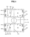
- FIGS. 1, 2 and 6(a) illustrate a first embodiment of a superconducting magnet apparatus according to the present invention. FIG. 1 is a sectional diagram illustrating the configuration of the entire apparatus. FIG. 2 is a perspective diagram illustrating an external view of the apparatus. FIG. 6(a) illustrates the first embodiment of the present invention by cutting away an upper right part of the first embodiment of the present invention illustrated in the sectional diagram of FIG. 1 in such a manner as to be able to be compared with other embodiments of the present invention.
- As shown in FIG. 1,
cylindrical vacuum enclosures center axis 22 of the magnet and as to face each other vertically. Theupper vacuum enclosure 10A is supported by supportingposts lower vacuum enclosure 10B.Coolant containers coolant 12 for superconductivity, are held in thevacuum enclosures superconducting coils - As the material of each of the aforementioned
superconducting coils 41A to 45A and 41B to 45B, Nb-Ti wires, which are usually frequently used as the material of superconducting coils, are employed. Further, liquid helium is used as thecoolant 12 for superconductivity. Moreover, thevacuum enclosures coolant containers - The supporting
posts upper vacuum enclosure 10A and may have a function of thermally connecting the upper andlower coolant containers lower coolant containers posts 26 is not always limited to two as illustrated in the figure but may be three or four. Alternatively, a single supporting post of the cantilever type may be employed so that a subject feels free and relaxed. - In FIG. 1, five sets of
superconducting coils 41A to 45A and 41B to 45B are placed in such a way as to be coaxial with thecenter axis 22A. Thus, a magnetic field of high magnetic homogeneity is formed in the uniformmagnetic field region 21. The functions of thesesuperconducting coils 41A to 45a and 41B to 45B are classified into the following three kinds. - First, the
superconducting coils magnetic field region 21. Regarding the main coils, generally, there is a tendency to enhance the magnetic homogeneity of a magnetic field generated therebetween when the diameters of these coils are increased under a condition wherein the distance therebetween is maintained at a constant value. Therefore, to obtain favorable magnetic homogeneity, it is better to increase the diameters of the coils as much as possible. In contrast, as the diameter of the main coil is increased, the magnetic field strength is decreased. Thus, the magnetomotive force of the main coil needed for obtaining a magnetic field having a constant strength, is increased. This leads to an increase in price of the superconducting magnet apparatus. Further, it is preferable for lowering a feeling of oppression of a subject to decrease the outside diameter of the apparatus as much as possible. The diameters of thesuperconducting coils vacuum enclosures - Next, the
superconducting coils main coils coils main coils main coils main coils magnetic field region 21 from lowering by the bucking coils 42A and 42B, it is important to move the aforesaid bucking coils 42A and 42B away from themain coils main coils coils main coils - Furthermore, the superconducting coils 43A, 44A, 45A and 43B, 44B, 45B are coils for correcting the magnetic homogeneity, for enhancing the magnetic homogeneity of a magnetic field generated in the uniform
magnetic field region 21. These coils for correcting themagnetic homogeneity 43A to 45A and 43B to 45B are provided so as to correct an inhomogeneous component of the magnetic field generated in the uniformmagnetic field region 21 formed by the aforementionedmain coils main coils magnetic homogeneity 43A to 45A and 43B to 45B do not need so large magnetomotive force as in the case of themain coils main coils main coils - As a practical example of this embodiment, if the outside diameter of the
main coils magnetic field region 21 is set at 450 mm, and the magnetic field strength is set at 1 Tesla, then the magnetic homogeneity of 5 ppm or less is achieved in the aforementioned uniformmagnetic field region 21. - According to the superconducting magnet apparatus of the present invention constructed as above described, there can be realized an apparatus which has a large opening and small magnetic field leakage. Moreover, iron is not used in order to suppress the magnetic field leakage. Thus, the weight of the apparatus can be small. Moreover, there is not caused a magnetic flux saturation which would be a problem caused if using iron. Therefore, even if the magnetic field strength becomes high, favorable magnetic homogeneity can be attained over the large uniform
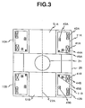
magnetic field region 21. - FIGS. 3 and 4 illustrate a second embodiment of the superconducting magnet apparatus according to the present invention. FIG. 3 is a sectional diagram illustrating the configuration of the entire apparatus. FIG. 4 is a perspective diagram illustrating an external view of the apparatus. As shown in FIG. 3, the
vacuum enclosures coolant containers central portions central portions vacuum enclosures - FIG. 5 illustrates a third embodiment of the superconducting magnet apparatus according to the present invention. As shown in FIG. 5, the distance between the opposed
main coils homogeneity 43A to 45A and the corresponding shim coils 43B to 45B. With such a configuration, the magnetic field strength of the magnetic field produced in the uniformmagnetic field region 21 can be increased without increasing the magnetomotive force of themain coils 41A and 41b. Furthermore, in addition to the aforementioned configuration,recess portions vacuum enclosures recess portions - Referring next to FIGS. 6(a), 6(b), 6(c) and 6(d), there are shown further other embodiments of the present invention, as compared with the first embodiment of the present invention. These embodiments are obtained by altering the placement of the main coils or the bucking coils in the first embodiment illustrated in FIG. 6(a).
- First, the embodiment illustrated in FIG. 6(b) is obtained by setting the diameter of the bucking coils 42A and 42B as being larger than that of the
main coils - Next, the embodiment illustrated in FIG. 6(c) is the case realized by dividing the bucking coils 42A and 42B of FIG. 6(a) into a set of two bucking coils 42AA and 42AB and another set of two bucking coils 42BA and 42BB, respectively. Generally, each coil is placed in a magnetic field generated by itself, and electric current flows therethrough. Thus, an electromagnetic force is exerted on each coil. This electromagnetic force, which depends on the magnetic field strength of the uniform
magnetic field region 21, may reach the strength of 100 t or so. Therefore, it is an important problem how to reduce this electromagnetic force when manufacturing a superconducting magnet apparatus. Thus, the magnetic force exerted onto each coil can be decreased by dividing the bucking coils 42A and 42B, onto which especially large magnetic forces are acted, into a set of two bucking coils 42AA and 42AB and another set of two bucking coils 42BA and 42BB, respectively, as illustrated in FIG. 6(c). Consequently, the conditions for manufacturing superconducting magnet apparatuses can be moderated. Furthermore, in the case of this embodiment, each of the bucking coils is divided into two coils. However, the present invention is not limited thereto. Namely, each of the bucking coils may be divided into three or more coils. - Furthermore, the embodiment illustrated in FIG. 6(d) is the case realized by dividing the
main coils main coils - Incidentally, in the foregoing description, coolants for superconductivity, such as liquid helium, are used as the cooling means for cooling superconductive materials. In the case that oxide superconductors are used as the superconductive materials, the material may be cooled by liquid nitrogen. Alternatively, the material may be cooled directly by a refrigerator, so that the apparatus sometimes does without using the coolant containers.
- As above described, according to the present invention, an opening, which accommodates a subject, of a superconducting magnet apparatus is enlarged to thereby prevent the subject from feeling claustrophobic. Further, an operator can easily get access to the subject. Moreover, there can be provided a superconducting magnet apparatus, whose magnetic field leakage is low and weight thereof is light, which can realize a large uniform magnetic field region even in the case of high magnetic field strength. Consequently, conditions for installing a superconducting magnet apparatus are moderated. Moreover, favorable pictures can be taken.
Claims (7)
- A superconducting magnet apparatus comprising: magnetic field generating sources, which are made of substances having superconducting properties and are operative to feed electric current for generating a uniform magnetic field, whose direction is a first direction, in a finite region;cooling means for cooling said magnetic field generating sources to a temperature, at which the substances exhibit the superconducting properties, and for maintaining said magnetic field generating sources at the temperature; andsupporting means for supporting said magnetic field generating sources,
wherein said magnetic field generating sources are placed equidistantly in such a way as to face each other across said uniform magnetic field region along the first direction and are composed of two sets of magnetic field generating device groups for feeding electric current in a coaxial direction with said first direction being made a center axis,
wherein each of the sets of magnetic field generating device groups comprises:one or more first magnetic field generating devices for feeding electric current which flows in a second direction along a circumference of a circle, whose center axis extends in said first direction, so as to generate a main component of said uniform magnetic field;one or more second magnetic field generating devices for feeding electric current which flows in a direction opposite to said second direction, so as to reduce a magnetic field generated outside said magnetic field generating sources; andone or more third magnetic field generating devices for feeding electric current which flows in a direction that is same as or opposite to she second direction so as to improve magnetic homogeneity of said uniform magnetic field, and,
wherein a diameter of said first magnetic field generating device is nearly equal to that of the second magnetic field generating device, a diameter of said third magnetic field generating device is less than that of the first magnetic field generating device, an amount of electric current fed to said third magnetic field generating device is less than an amount of electric current fed to said first magnetic field generating device, and a distance between said first magnetic field generating devices facing each other across said uniform magnetic field region is shorter than that between said second magnetic field generating devices facing each other across said uniform magnetic field region. - A superconducting magnet apparatus according to claim 1, wherein the diameter of said second magnetic field generating device may be set as being larger than that of said first magnetic field generating device.
- A superconducting magnet apparatus according to claim 1 or 2, wherein said second magnetic field generating devices each consists of magnetic field generating elements having a plurality of different diameters, and said magnetic field generating elements are provided in such a manner that a diameter of said magnetic field generating elements corresponding to each other is increased in proportion to a distance between said magnetic field generating elements corresponding to each other and facing each other across a uniform magnetic field generating region.
- A superconducting magnet apparatus according to any one of claims 1 to 3, wherein said first magnetic field generating devices each consists of magnetic field generating elements having a plurality of different diameters, and said magnetic field generating elements are provided in such a manner that a diameter of said magnetic field generating elements corresponding to each other is increased in proportion to a distance between the magnetic field generating elements corresponding to each other and facing each other across said uniform magnetic field generating region.
- A superconducting magnet apparatus according to any one of claims 1 to 4, wherein a distance between said first magnetic field generating devices facing each other across said uniform magnetic field generating region is set as being less than a distance between said second magnetic field generating devices facing each other across said uniform magnetic field generating region and further is set as being less than a distance between said third magnetic field generating devices facing each other across said uniform magnetic field generating region.
- A superconducting magnet apparatus according to any one of claims 1 to 5, wherein said cooling means has vacuum enclosures for containing said magnetic field generating sources, and an outer circumferential portion of each of said vacuum enclosures protrudes to a side at which said uniform magnetic field generating region exists.
- A superconducting magnet apparatus according to any one of claims 1 to 6, wherein each of said magnetic field generating sources is constituted by a coil obtained by winding a wire made of a substance having a superconducting property.
Applications Claiming Priority (3)
| Application Number | Priority Date | Filing Date | Title |
|---|---|---|---|
| JP336023/95 | 1995-11-30 | ||
| JP33602395A JP3731231B2 (en) | 1995-11-30 | 1995-11-30 | Superconducting magnet device |
| PCT/JP1996/003512 WO1997020326A1 (en) | 1995-11-30 | 1996-11-29 | Superconducting magnet device |
Publications (3)
| Publication Number | Publication Date |
|---|---|
| EP0807940A1 true EP0807940A1 (en) | 1997-11-19 |
| EP0807940A4 EP0807940A4 (en) | 2000-01-19 |
| EP0807940B1 EP0807940B1 (en) | 2007-01-17 |
Family
ID=18294903
Family Applications (1)
| Application Number | Title | Priority Date | Filing Date |
|---|---|---|---|
| EP96939331A Expired - Lifetime EP0807940B1 (en) | 1995-11-30 | 1996-11-29 | Superconducting magnet device |
Country Status (5)
| Country | Link |
|---|---|
| US (2) | US6580346B1 (en) |
| EP (1) | EP0807940B1 (en) |
| JP (1) | JP3731231B2 (en) |
| DE (1) | DE69636849T2 (en) |
| WO (1) | WO1997020326A1 (en) |
Cited By (6)
| Publication number | Priority date | Publication date | Assignee | Title |
|---|---|---|---|---|
| EP1036541A1 (en) * | 1997-12-01 | 2000-09-20 | Hitachi Medical Corporation | Magnet apparatus and mri apparatus |
| WO2002027345A1 (en) * | 2000-09-26 | 2002-04-04 | Koninklijke Philips Electronics N.V. | Vertical field type mri apparatus with a conical cavity situated in the main magnet |
| WO2002027346A1 (en) * | 2000-09-26 | 2002-04-04 | Koninklijke Philips Electronics N.V. | Vertical field type mri apparatus with a conical gradient coil situated in the main magnet |
| EP1214906A1 (en) * | 1999-09-16 | 2002-06-19 | Hitachi Medical Corporation | Open-type magnet device for mri |
| EP1340456A1 (en) * | 2000-12-05 | 2003-09-03 | Hitachi, Ltd. | Low-leakage magnetic-field magnet and shield coil assembly |
| EP1521095A1 (en) * | 2003-09-30 | 2005-04-06 | Hitachi, Ltd. | Superconducting magnet apparatus |
Families Citing this family (29)
| Publication number | Priority date | Publication date | Assignee | Title |
|---|---|---|---|---|
| US20030195410A1 (en) * | 1995-08-10 | 2003-10-16 | James Winter | Method of treatment using magnetic resonance and apparatus therefor |
| JPH09190913A (en) * | 1996-01-10 | 1997-07-22 | Hitachi Medical Corp | Superconducting magnet device and magnetic resonance imaging apparatus using this device |
| JP2002034947A (en) | 1997-10-24 | 2002-02-05 | Hitachi Ltd | Magnet device and mri apparatus using the same |
| JP2000046999A (en) * | 1998-07-31 | 2000-02-18 | Rikagaku Kenkyusho | Uniform magnetic field generator |
| US20040041565A1 (en) * | 2002-05-08 | 2004-03-04 | Shigeru Kakugawa | NMR magnet device for solution analysis and NMR apparatus |
| JP3845048B2 (en) * | 2002-08-27 | 2006-11-15 | ジーイー・メディカル・システムズ・グローバル・テクノロジー・カンパニー・エルエルシー | Magnetic resonance imaging device |
| JP4034224B2 (en) * | 2003-04-24 | 2008-01-16 | 株式会社日立製作所 | Magnet for nuclear magnetic resonance apparatus and nuclear magnetic resonance analyzer using the same |
| EP1735631A2 (en) * | 2004-04-01 | 2006-12-27 | Liposcience, Inc. | Nmr clinical analyzers and related methods, systems, modules and computer program products for clinical evaluation of biosamples |
| JP2006115934A (en) * | 2004-10-19 | 2006-05-11 | Mitsubishi Electric Corp | Magnet apparatus and magnetic resonance imaging system using the same |
| JP4639763B2 (en) * | 2004-11-12 | 2011-02-23 | 三菱電機株式会社 | Magnetic resonance imaging system |
| US7224167B2 (en) * | 2004-11-30 | 2007-05-29 | General Electric Company | Magnetic field generating apparatus and method for magnetic resonance imaging |
| US7375528B2 (en) * | 2005-03-29 | 2008-05-20 | Magnetica Limited | Shielded, asymmetric magnets for use in magnetic resonance imaging |
| US7274192B2 (en) * | 2005-05-31 | 2007-09-25 | General Electric Company | Combined open and closed magnet configuration for MRI |
| JP4610449B2 (en) * | 2005-09-01 | 2011-01-12 | 株式会社日立製作所 | Magnet device |
| JP4705528B2 (en) * | 2006-01-05 | 2011-06-22 | 株式会社日立製作所 | Superconducting magnet apparatus and magnetic resonance imaging apparatus |
| US7560929B2 (en) * | 2006-08-14 | 2009-07-14 | Fonar Corporation | Ferromagnetic frame magnet with superconducting coils |
| CN101765399B (en) * | 2007-08-01 | 2013-08-21 | 金溶进 | Superconductor with enhanced high magenetic field properties, manufacturing method thereof, and mri apparatus comprising the same |
| JP4542573B2 (en) * | 2007-08-07 | 2010-09-15 | 株式会社日立製作所 | Active shield type superconducting electromagnet apparatus and magnetic resonance imaging apparatus |
| JP2009141255A (en) * | 2007-12-10 | 2009-06-25 | Kobe Steel Ltd | Superconductive electromagnet |
| JP4762226B2 (en) * | 2007-12-20 | 2011-08-31 | 三菱電機株式会社 | Superconducting magnet device |
| US20090237192A1 (en) * | 2008-03-20 | 2009-09-24 | General Electric Company | Magnetic resonance imaging system and apparatus having a multiple-section |
| WO2009135264A1 (en) * | 2008-05-08 | 2009-11-12 | The University Of Queensland | Arrangement of coils for mri apparatus |
| US8400157B2 (en) * | 2008-08-29 | 2013-03-19 | Geotech Airborne Limited | Bucking coil and B-field measurement system and apparatus for time domain electromagnetic measurements |
| FR2962844B1 (en) * | 2010-07-16 | 2013-08-30 | Commissariat Energie Atomique | COMPACT SUPERCONDUCTING MAGNET DEVICE |
| JP2012234939A (en) | 2011-04-28 | 2012-11-29 | High Energy Accelerator Research Organization | Magnetic shielding material for superconducting magnet |
| JP2012234938A (en) * | 2011-04-28 | 2012-11-29 | High Energy Accelerator Research Organization | Low-temperature heat transfer material |
| CN104157391B (en) * | 2014-08-15 | 2017-01-11 | 中国科学院电工研究所 | Method for obtaining shortest length of magnetic resonance imaging superconducting magnet |
| JP6460922B2 (en) * | 2015-06-16 | 2019-01-30 | 株式会社日立製作所 | Superconducting deflection electromagnet for beam and beam deflection apparatus using the same |
| WO2017029676A1 (en) * | 2015-08-19 | 2017-02-23 | KAFRI, Amizur | Hybrid superconducting magnetic device |
Citations (5)
| Publication number | Priority date | Publication date | Assignee | Title |
|---|---|---|---|---|
| US4766378A (en) * | 1986-11-28 | 1988-08-23 | Fonar Corporation | Nuclear magnetic resonance scanners |
| US5382904A (en) * | 1992-04-15 | 1995-01-17 | Houston Advanced Research Center | Structured coil electromagnets for magnetic resonance imaging and method for fabricating the same |
| US5410287A (en) * | 1994-04-05 | 1995-04-25 | General Electric Company | Open MRI magnet with uniform magnetic field |
| US5448214A (en) * | 1994-06-15 | 1995-09-05 | General Electric Company | Open MRI magnet with superconductive shielding |
| GB2289343A (en) * | 1994-05-13 | 1995-11-15 | Bruker Analytische Messtechnik | A side-access MRI magnet having both active and passive shims |
Family Cites Families (18)
| Publication number | Priority date | Publication date | Assignee | Title |
|---|---|---|---|---|
| DE3123493A1 (en) * | 1981-06-13 | 1982-12-30 | Bruker Analytische Meßtechnik GmbH, 7512 Rheinstetten | ELECTROMAGNET FOR NMR TOMOGRAPHY |
| JPH0620011B2 (en) * | 1983-12-29 | 1994-03-16 | 株式会社日立製作所 | Superconducting magnetic field generator |
| JPS61125109A (en) * | 1984-11-22 | 1986-06-12 | Hitachi Ltd | Superconductive magnetic device |
| JPS61172040A (en) * | 1985-01-25 | 1986-08-02 | Sumitomo Electric Ind Ltd | Magnetic field generation apparatus for nuclear magnetic resonance |
| JPS6343649A (en) * | 1986-08-08 | 1988-02-24 | 株式会社日立メディコ | Nuclear magnetic resonance imaging apparatus |
| JPS63272335A (en) * | 1986-11-18 | 1988-11-09 | Toshiba Corp | Magnetic resonance imaging apparatus |
| US4829252A (en) * | 1987-10-28 | 1989-05-09 | The Regents Of The University Of California | MRI system with open access to patient image volume |
| JPH01165106A (en) * | 1987-12-22 | 1989-06-29 | Asahi Chem Ind Co Ltd | Magnetic field generator |
| DE3907927A1 (en) * | 1989-03-11 | 1990-09-20 | Bruker Analytische Messtechnik | MAGNETIC SYSTEM |
| US5134374A (en) | 1989-06-01 | 1992-07-28 | Applied Superconetics | Magnetic field control apparatus |
| JP2803306B2 (en) * | 1990-03-31 | 1998-09-24 | 株式会社島津製作所 | Magnet device for MRI |
| JPH05182828A (en) * | 1992-01-06 | 1993-07-23 | Hitachi Cable Ltd | Superconducting magnet for nmr analysis |
| US5359310A (en) * | 1992-04-15 | 1994-10-25 | Houston Advanced Research Center | Ultrashort cylindrical shielded electromagnet for magnetic resonance imaging |
| JP3266355B2 (en) * | 1993-02-05 | 2002-03-18 | 住友特殊金属株式会社 | Magnetic field generator for superconducting MRI |
| US5596303A (en) * | 1993-02-22 | 1997-01-21 | Akguen Ali | Superconductive magnet system with low and high temperature superconductors |
| GB2299672A (en) * | 1995-04-07 | 1996-10-09 | Oxford Magnet Tech | Attachment method for superconducting MRI coil |
| US5568104A (en) * | 1995-10-23 | 1996-10-22 | General Electric Company | Open MRI superconductive magnet with cryogenic-fluid cooling |
| US5565831A (en) * | 1995-10-23 | 1996-10-15 | General Electric Company | Shielded and open MRI magnet |
-
1995
- 1995-11-30 JP JP33602395A patent/JP3731231B2/en not_active Expired - Fee Related
-
1996
- 1996-11-29 EP EP96939331A patent/EP0807940B1/en not_active Expired - Lifetime
- 1996-11-29 WO PCT/JP1996/003512 patent/WO1997020326A1/en active IP Right Grant
- 1996-11-29 DE DE69636849T patent/DE69636849T2/en not_active Expired - Lifetime
-
1997
- 1997-07-16 US US08/895,269 patent/US6580346B1/en not_active Expired - Fee Related
-
2003
- 2003-03-18 US US10/391,284 patent/US6816047B2/en not_active Expired - Fee Related
Patent Citations (5)
| Publication number | Priority date | Publication date | Assignee | Title |
|---|---|---|---|---|
| US4766378A (en) * | 1986-11-28 | 1988-08-23 | Fonar Corporation | Nuclear magnetic resonance scanners |
| US5382904A (en) * | 1992-04-15 | 1995-01-17 | Houston Advanced Research Center | Structured coil electromagnets for magnetic resonance imaging and method for fabricating the same |
| US5410287A (en) * | 1994-04-05 | 1995-04-25 | General Electric Company | Open MRI magnet with uniform magnetic field |
| GB2289343A (en) * | 1994-05-13 | 1995-11-15 | Bruker Analytische Messtechnik | A side-access MRI magnet having both active and passive shims |
| US5448214A (en) * | 1994-06-15 | 1995-09-05 | General Electric Company | Open MRI magnet with superconductive shielding |
Non-Patent Citations (1)
| Title |
|---|
| See also references of WO9720326A1 * |
Cited By (13)
| Publication number | Priority date | Publication date | Assignee | Title |
|---|---|---|---|---|
| EP1036541A1 (en) * | 1997-12-01 | 2000-09-20 | Hitachi Medical Corporation | Magnet apparatus and mri apparatus |
| EP1036541A4 (en) * | 1997-12-01 | 2005-11-02 | Hitachi Medical Corp | Magnet apparatus and mri apparatus |
| EP1214906A4 (en) * | 1999-09-16 | 2006-02-22 | Hitachi Medical Corp | Open-type magnet device for mri |
| EP1214906A1 (en) * | 1999-09-16 | 2002-06-19 | Hitachi Medical Corporation | Open-type magnet device for mri |
| US6741078B2 (en) | 2000-09-26 | 2004-05-25 | Koninklijke Philips Electronics N.V. | Vertical field type MRI apparatus with a conical cavity situated in the main magnet |
| US6618606B2 (en) | 2000-09-26 | 2003-09-09 | Koninklijke Philips Electronics N.V. | Vertical field type MRI apparatus with a conical gradient coil situated in the main magnet |
| WO2002027346A1 (en) * | 2000-09-26 | 2002-04-04 | Koninklijke Philips Electronics N.V. | Vertical field type mri apparatus with a conical gradient coil situated in the main magnet |
| WO2002027345A1 (en) * | 2000-09-26 | 2002-04-04 | Koninklijke Philips Electronics N.V. | Vertical field type mri apparatus with a conical cavity situated in the main magnet |
| US7009476B2 (en) | 2000-09-26 | 2006-03-07 | Koninklijke Philips Electronics, N.V. | Vertical field type MRI apparatus with a conical cavity situated in the main magnet |
| EP1340456A1 (en) * | 2000-12-05 | 2003-09-03 | Hitachi, Ltd. | Low-leakage magnetic-field magnet and shield coil assembly |
| EP1340456A4 (en) * | 2000-12-05 | 2005-11-09 | Hitachi Ltd | Low-leakage magnetic-field magnet and shield coil assembly |
| EP1521095A1 (en) * | 2003-09-30 | 2005-04-06 | Hitachi, Ltd. | Superconducting magnet apparatus |
| US8134433B2 (en) | 2003-09-30 | 2012-03-13 | Hitachi, Ltd. | Superconducting magnet apparatus |
Also Published As
| Publication number | Publication date |
|---|---|
| WO1997020326A1 (en) | 1997-06-05 |
| JPH09153408A (en) | 1997-06-10 |
| JP3731231B2 (en) | 2006-01-05 |
| US20030155998A1 (en) | 2003-08-21 |
| EP0807940B1 (en) | 2007-01-17 |
| DE69636849T2 (en) | 2007-11-08 |
| US6580346B1 (en) | 2003-06-17 |
| US6816047B2 (en) | 2004-11-09 |
| DE69636849D1 (en) | 2007-03-08 |
| EP0807940A4 (en) | 2000-01-19 |
Similar Documents
| Publication | Publication Date | Title |
|---|---|---|
| EP0807940B1 (en) | Superconducting magnet device | |
| EP0817211B1 (en) | Superconducting magnet device and magnetic resonance imaging device using the same | |
| EP0770881B1 (en) | Shielded and open MRI magnet | |
| US5410287A (en) | Open MRI magnet with uniform magnetic field | |
| JP2888452B2 (en) | Magnet device | |
| US5999075A (en) | Open magnet with shielding | |
| US5574417A (en) | Open MRI magnet with homogeneous imaging volume | |
| US6396376B1 (en) | Apparatus and method for a superconductive magnet with pole piece | |
| EP0826977B1 (en) | Compact MRI superconducting magnet | |
| US5361054A (en) | Magnet system | |
| EP1464976B1 (en) | NMR spectrometer magnet | |
| EP0937994B1 (en) | Open and shielded supercondutive magnet | |
| EP0770883A1 (en) | Cryogenic-fluid-cooled open MRI magnet with uniform magnetic field | |
| US5568110A (en) | Closed MRI magnet having reduced length | |
| US7271590B2 (en) | MRI magnet apparatus for vertically and circularly suppressing the magnetic fringe field | |
| US4931759A (en) | Magnetic resonance imaging magnet having minimally symmetric ferromagnetic shield | |
| US5521571A (en) | Open MRI magnet with uniform imaging volume | |
| US6812702B2 (en) | Magnetic resonance imaging apparatus | |
| JPH09276246A (en) | Superconducting magnet device | |
| US11789102B2 (en) | Magnetic resonance imaging device | |
| JP3990410B2 (en) | Superconducting magnet and magnetic resonance imaging apparatus | |
| JPH07204174A (en) | Magnetostatic field generator for magnetic resonance imaging system | |
| JPH1099296A (en) | Split type magnetic field generator for mri use |
Legal Events
| Date | Code | Title | Description |
|---|---|---|---|
| PUAI | Public reference made under article 153(3) epc to a published international application that has entered the european phase |
Free format text: ORIGINAL CODE: 0009012 |
|
| AK | Designated contracting states |
Kind code of ref document: A1 Designated state(s): DE FR GB IT |
|
| 17P | Request for examination filed |
Effective date: 19971204 |
|
| D17D | Deferred search report published (deleted) | ||
| A4 | Supplementary search report drawn up and despatched |
Effective date: 19991206 |
|
| AK | Designated contracting states |
Kind code of ref document: A4 Designated state(s): DE FR GB IT |
|
| RIC1 | Information provided on ipc code assigned before grant |
Free format text: 7H 01F 7/22 A, 7G 01R 33/38 B, 7G 01R 33/3815 B, 7G 01R 33/421 B, 7G 01R 33/3875 B |
|
| 17Q | First examination report despatched |
Effective date: 20010830 |
|
| GRAP | Despatch of communication of intention to grant a patent |
Free format text: ORIGINAL CODE: EPIDOSNIGR1 |
|
| RIC1 | Information provided on ipc code assigned before grant |
Ipc: G01N 24/08 20060101ALI20060418BHEP Ipc: G01R 33/3875 20060101ALI20060418BHEP Ipc: G01R 33/421 20060101ALI20060418BHEP Ipc: G01R 33/3815 20060101ALI20060418BHEP Ipc: G01R 33/38 20060101ALI20060418BHEP Ipc: H01F 6/06 20060101AFI20060418BHEP |
|
| GRAS | Grant fee paid |
Free format text: ORIGINAL CODE: EPIDOSNIGR3 |
|
| RAP1 | Party data changed (applicant data changed or rights of an application transferred) |
Owner name: HITACHI MEDICAL CORPORATION |
|
| GRAA | (expected) grant |
Free format text: ORIGINAL CODE: 0009210 |
|
| AK | Designated contracting states |
Kind code of ref document: B1 Designated state(s): DE FR GB IT |
|
| REG | Reference to a national code |
Ref country code: GB Ref legal event code: FG4D |
|
| REF | Corresponds to: |
Ref document number: 69636849 Country of ref document: DE Date of ref document: 20070308 Kind code of ref document: P |
|
| PLBE | No opposition filed within time limit |
Free format text: ORIGINAL CODE: 0009261 |
|
| STAA | Information on the status of an ep patent application or granted ep patent |
Free format text: STATUS: NO OPPOSITION FILED WITHIN TIME LIMIT |
|
| 26N | No opposition filed |
Effective date: 20071018 |
|
| PG25 | Lapsed in a contracting state [announced via postgrant information from national office to epo] |
Ref country code: IT Free format text: LAPSE BECAUSE OF FAILURE TO SUBMIT A TRANSLATION OF THE DESCRIPTION OR TO PAY THE FEE WITHIN THE PRESCRIBED TIME-LIMIT Effective date: 20070117 Ref country code: FR Free format text: LAPSE BECAUSE OF FAILURE TO SUBMIT A TRANSLATION OF THE DESCRIPTION OR TO PAY THE FEE WITHIN THE PRESCRIBED TIME-LIMIT Effective date: 20070907 |
|
| PG25 | Lapsed in a contracting state [announced via postgrant information from national office to epo] |
Ref country code: FR Free format text: LAPSE BECAUSE OF FAILURE TO SUBMIT A TRANSLATION OF THE DESCRIPTION OR TO PAY THE FEE WITHIN THE PRESCRIBED TIME-LIMIT Effective date: 20070117 |
|
| PGFP | Annual fee paid to national office [announced via postgrant information from national office to epo] |
Ref country code: GB Payment date: 20101022 Year of fee payment: 15 |
|
| PGFP | Annual fee paid to national office [announced via postgrant information from national office to epo] |
Ref country code: DE Payment date: 20111130 Year of fee payment: 16 |
|
| GBPC | Gb: european patent ceased through non-payment of renewal fee |
Effective date: 20121129 |
|
| REG | Reference to a national code |
Ref country code: DE Ref legal event code: R119 Ref document number: 69636849 Country of ref document: DE Effective date: 20130601 |
|
| PG25 | Lapsed in a contracting state [announced via postgrant information from national office to epo] |
Ref country code: DE Free format text: LAPSE BECAUSE OF NON-PAYMENT OF DUE FEES Effective date: 20130601 |
|
| PG25 | Lapsed in a contracting state [announced via postgrant information from national office to epo] |
Ref country code: GB Free format text: LAPSE BECAUSE OF NON-PAYMENT OF DUE FEES Effective date: 20121129 |