EP0803935A2 - A terminal metal fitting assembling structure - Google Patents
A terminal metal fitting assembling structure Download PDFInfo
- Publication number
- EP0803935A2 EP0803935A2 EP97105776A EP97105776A EP0803935A2 EP 0803935 A2 EP0803935 A2 EP 0803935A2 EP 97105776 A EP97105776 A EP 97105776A EP 97105776 A EP97105776 A EP 97105776A EP 0803935 A2 EP0803935 A2 EP 0803935A2
- Authority
- EP
- European Patent Office
- Prior art keywords
- terminal metal
- metal fitting
- metal fittings
- plate
- securing
- Prior art date
- Legal status (The legal status is an assumption and is not a legal conclusion. Google has not performed a legal analysis and makes no representation as to the accuracy of the status listed.)
- Granted
Links
Images


Classifications
-
- H—ELECTRICITY
- H01—ELECTRIC ELEMENTS
- H01R—ELECTRICALLY-CONDUCTIVE CONNECTIONS; STRUCTURAL ASSOCIATIONS OF A PLURALITY OF MUTUALLY-INSULATED ELECTRICAL CONNECTING ELEMENTS; COUPLING DEVICES; CURRENT COLLECTORS
- H01R11/00—Individual connecting elements providing two or more spaced connecting locations for conductive members which are, or may be, thereby interconnected, e.g. end pieces for wires or cables supported by the wire or cable and having means for facilitating electrical connection to some other wire, terminal, or conductive member, blocks of binding posts
- H01R11/11—End pieces or tapping pieces for wires, supported by the wire and for facilitating electrical connection to some other wire, terminal or conductive member
- H01R11/12—End pieces terminating in an eye, hook, or fork
-
- H—ELECTRICITY
- H01—ELECTRIC ELEMENTS
- H01R—ELECTRICALLY-CONDUCTIVE CONNECTIONS; STRUCTURAL ASSOCIATIONS OF A PLURALITY OF MUTUALLY-INSULATED ELECTRICAL CONNECTING ELEMENTS; COUPLING DEVICES; CURRENT COLLECTORS
- H01R4/00—Electrically-conductive connections between two or more conductive members in direct contact, i.e. touching one another; Means for effecting or maintaining such contact; Electrically-conductive connections having two or more spaced connecting locations for conductors and using contact members penetrating insulation
- H01R4/28—Clamped connections, spring connections
- H01R4/30—Clamped connections, spring connections utilising a screw or nut clamping member
- H01R4/34—Conductive members located under head of screw
Definitions
- the present invention relates to a terminal metal fitting assembling structure which is able to bring a plurality of terminal metal fittings into contact with each other by use of a bolt or the like.
- ground terminals when a plurality of ground terminals individually connected to a plurality of equipments are to be mounted onto a vehicle body, there is conventionally used a structure in which the ground terminals are assembled together into an integral assembly in such a manner that they are overlapped with each other and, after then, the assembly is fixedly fastened to the vehicle body by use of a bolt.
- a bolt by tightening the bolt, not only the ground terminals can be closely contacted with the vehicle body but also the ground terminals can be closely contacted with each other. Due to such close contact between the ground terminals, even the ground terminals that are not in direct contact with the vehicle body are also allowed to be in indirect conduction with the vehicle body.
- the present invention aims at eliminating the above-mentioned drawbacks found in the conventional terminal metal fitting assembling structure. Accordingly, it is an object of the invention to provide a terminal metal fitting assembling structure which can secure contact reliability between the terminal metal fittings assembled together.
- a terminal metal fitting assembling structure includes: a plurality of terminal metal fittings including a first terminal metal fitting and a second terminal metal fitting, the second terminal metal fitting having a projecting portion on a first surface thereof opposing to the first terminal metal fitting to form a clearance between the first and second metal fittings when the first and second metal fittings are overlapped; and a tightening member which fastens the metal fittings so that the first and second metal fittings are maintained in contact with each other; wherein the tightening member tightly fastens areas of the first and second metal fittings situated inside of the projecting portion to flexibly deform the second terminal metal fitting to approach the first and second metal fittings each other, so that the projecting portions are contacted with the first metal fitting with a resilient force.
- the terminal metal fittings are overlapped with each other.
- the two terminal metal fittings are overlapped with each other through the projecting portions while forming a clearance between them.
- the terminal metal fittings that is, the clearance forming portions thereof are flexibly deformed in a direction where they are made to approach each other, whereas there is generated a resilient force in the portions of the terminal metal fittings against which the projecting portions are butted.
- the two terminal metal fittings are in contact with each other through the projecting portions, reliability on the assembled condition of the two terminal metal fittings can be enhanced. Also, because the tightening member fastens tight the portions of the terminal metal fittings inside the pressing portions but does not tighten the projecting portions directly, even if the terminal metal fittings are fastened excessively tight, the pressing portions can be prevented from be deformed, damaged and the like.
- the invention is applied to a ground terminal metal fitting assembling structure in which two terminal metal fittings are assembled together and the resultant assembly is then mounted onto the body of a vehicle.
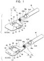
- first terminal metal fitting 10 which is shown in the upper portion of Fig. 1; and, the other is a second terminal metal fitting 30 shown below of the first terminal metal fitting 10 Fig. 1.
- the first terminal metal fitting 10 To form the first terminal metal fitting 10, a conductive metal plate is punched out into a given shape and, after then, the punched metal plate is bent; and, the first terminal metal fitting 10 includes an assembling portion 11 and an electric wire connecting portion 24.
- the assembling portion 11 includes a plate-like overlap portion 12 composed of two flat plates arranged in parallel to each other but spaced apart from each other (hereinafter, a plate-like overlap portion disposed on far side to the electric wire connecting portion 44 in Fig. 1 is referred to as 12A, while a plate-like overlap portion disposed on the near side thereto in Fig.
- a plate-like securing portion 13 which is disposed between the respective one-side end portions of the two plate-like overlap portions 12A and 12B in such a manner that the securing portion 13 spans the two overlap portions 12A and 12B
- a plate-like receive portion 14 disposed between the respective end portions of the two plate-like overlap portions 12A and 12B opposite to the above-mentioned end portions thereof for the securing portion 13 in such a manner that the receive portion 14 spans the two overlap portions 12A and 12B.
- the plate-like two overlap portions 12A and 12B are set flush with each other, while the plate-like overlap portion 12A is formed slightly wider than the plate-like overlap portion 12B on the leading end side thereof (in Fig.
- the securing portion 13 and receive portion 14 are set flush with each other are also set at a height which is lower than the two plate-like overlap portions 12A and 12B by an amount substantially equal to the plate thickness of the plate-like overlap portion 12A or 12B.
- a displacement restriction portion 15 which is set flush with the securing portion 13 and extends out in the opposite direction of the receive portion 14.
- a securing claw 16 by cutting and raising the same upper surface, which securing claw 16 can be engaged with a securing hole 39 formed in a second terminal metal fitting 30 to be discussed later.
- an inclined guide surface 17 which is used to facilitate an engaging operation between the securing portion 13 and a receive portion 34 formed in the second terminal metal fitting 30 to be discussed later.
- escape grooves 18 into which connecting portions between the two plate-like overlap portions 32A, 32B of the second terminal metal fitting 30 and a receive portion 34 formed in the second terminal metal fitting 30 can be inserted.
- the receive portion 14 further includes a projecting portion 20 which is set flush with the receive portion 14 and extends toward the displacement restriction portion 15 and, in the upper surface of the projecting portion 20, there is formed an inclined guide surface 21 which is used to facilitate the fitting operation of the securing hole 19 with the securing claw 36 of the second terminal metal fitting 30. Also, between the projecting portion 20 and the two plate-like overlap portions 12A, 12B, there are formed escape groove into which connecting portions existing between a securing portion 33 and two plate-like overlap portions 32A, 32B respectively formed in the second terminal metal fitting 30 can be retreated.
- the mutually opposed edges of the securing portion 13 and projecting portion 20 are respectively formed as arc-shaped edges which are concentric with each other and equal in diameter to each other.
- the two plate-like overlap portions 12A and 12B of the first terminal metal fitting 10 are arranged in such a manner that the side edges thereof can be in contact with virtual circles which are respectively concentric and equal in diameter with such arcs. Further, a space enclosed by these edges provides an insertion hole 23 into which a tightening bolt 50 can be fitted.
- An electric wire connecting portion 24 is formed integrally with the above-mentioned assembling portion 11. That is, the electric wire connecting portion 24 is arranged in such a manner that it extends from the end portion side edge of the plate-like overlap portion 12B on the receive portion 14 side thereof toward a direction at right angles to the longitudinal direction of the plate-like overlap portion 12B.
- the electric wire connecting portion 24 includes an insulation barrel 24A and a wire barrel 24B.
- the insulation barrel 24A is crimped from the side of the associated equipments (not shown) on a resin cover Wa provided in the terminal portion of a ground wire W, whereas the wire barrel 24B is crimped on a core wire Wb which is exposed by peeling off the resin cover Wa of the ground wire W.
- a conductive metal plate is punched out into a given shape and the thus punched metal plate is then bent, so that it includes an assembling portion 31 and an electric wire connecting portion 44.
- the assembling portion 31 has a structure in which the assembling portion 11 of the first terminal metal fitting 10 is turned upside down. That is, the plate-like overlap portion 32 (a plate-like overlap portion disposed on far side to the electric wire connecting portion 44 in Fig. 1 is referred to as 32A, whereas a plate-like overlap portion on the near side thereto in Fig.
- the assembling portion 31 of the second terminal metal fitting 30 can be overlapped with the lower surface sides of the plate-like overlap portions 12A and 12B of the first terminal metal fitting 10, respectively; and, the securing portion 33 and receive portion 34 of the assembling portion 31 can be overlapped with the upper surface sides of the receive portion 14 and securing portion 13 of the first terminal metal fitting 10, respectively.
- the assembling portion 31 of the second terminal metal fitting 30 as well, there are formed a displacement restriction portion 35 and a securing claw 36 in the securing portion 33 and, there are formed a securing hole 39 and a projecting portion 40 in the receive portion 34.
- an insertion hole 43 which is identical with the insertion hole 23 of the first terminal metal fitting 10 and there are formed escape grooves 38 and 42 respectively between the displacement restriction portion 35 and two plate-like overlap portions 32A, 32B as well as between the projecting portion 40 and two plate-like overlap portions 32A, 32B.
- the electric wire connecting portion 44 similarly to the electric connecting portion 24 of the first terminal metal fitting 10, includes an insulation barrel 44A and a wire barrel 44B which are crimped on a ground wire W.
- the electric wire connecting portion 44 is arranged in such a manner that it extends from the end portion side edge of the plate-like overlap portion 32B on the receive portion 34 side thereof in a direction at right angles to the longitudinal direction of the plate-like overlap portion 32B. Therefore, when the second terminal metal fitting 30 is assembled with the first terminal metal fitting 10, the electric wire connecting portion 44 can be arranged in parallel to the electric wire connecting portion 24 of the first terminal metal fitting 10.
- the second terminal metal fitting 30 includes the two plate-like overlap portions 32A and 32B.
- a projecting portion 45 that is, a pressing portion which is the subject matter of the present invention which extends along the longitudinal direction of the overlap portion 32A (that is, a direction in which the two terminal metal fittings are assembled).
- the projecting portion 45 is formed in vicinity of the tip portion of the plate-like overlap portion 32A and, when the first and second terminal metal fittings 10 and 30 are assembled together, is situated outside of a position where the head portion 50A of the tightening bolt 50 is directly pressed against the first terminal metal fitting 10, that is, outside of a position which is an area A shown by meshes in Fig. 3. Therefore, tightening by the tightening bolt 50 is executed on an area existing inside of the projecting portion 45 and is not executed directly on the projecting portion 45 itself.
- the height of the projecting portion 45 is set in such a manner that, when the securing portions 13, 33 and receive portions 14, 34 are in contact with each other, the top portion of the projecting portion 45 is higher than the height of the lower surface of the plate-like overlap portion 12A of the first terminal fitting member 10. Further, when the two terminal metal fittings 10 and 30 are assembled together, inside of the projecting portion 45, there can be formed a slight clearance 41 (see Fig. 4) between the two plate-like overlap portions 12A and 32A.
- first terminal metal fitting 10 is assembled with the second metal fitting 30.
- first terminal metal fitting 10 is disposed above the second metal fitting 30 and the securing portions 13 and 33 thereof are respectively inserted into their mating insertion holes 43 and 23.
- the securing portions 13 and 33 are further slided in the longitudinal direction of the plate-like overlap portions 12 and 32 (which is hereinafter referred to as an assembling direction) so that the insertion holes 23 and 43 can be matched to each other.
- the displacement restriction portion 15 of the first terminal metal fitting 10 is arranged under the receive portion 34 of the second terminal metal fitting 30 and, at the same time, the displacement restriction portion 35 of the second terminal metal fitting 30 is arranged onto the receive portion 14 of the first terminal metal fitting 10.
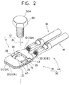
- the securing claws 16 and 36 are respectively fitted with the securing holes 19 and 39, which completes the assembling operation of the two terminal metal fittings 10 and 30 (see Fig. 2).
- the tightening bolt 50 is inserted into the insertion holes 23 and 43 of the two terminal metal fittings 10 and 30 which have been assembled together, and the two assembled terminal metal fittings 10 and 30 are then fastened tight by the tightening bolt 50 in the direction of a vehicle body 50.
- the respective plate-like overlap portions 12 and 32 of the two terminal metal fittings 10 and 30 are brought into contact with each other and the second terminal metal fitting 30 is pressed against the vehicle body 51 side.
- the portion of the plate-like overlap portion 12A of the first terminal metal fitting 10 that is situated inside of the portion against which the projecting portion 45 is butted, that is, the portion of the plate-like overlap portion 12A that forms the clearance 41 with respect to the plate-like overlap portion 32A of the second terminal metal fitting 30 is flexibly deformed and is pressed in a direction where it approaches the plate-like overlap portion 32A of the second terminal metal fitting 30 (see Fig. 4).
- the provision of the projecting portion 45 makes it possible to increase the contact pressure between the two terminal metal fittings 10 and 30, there can be secured reliability on the contact between the two terminal metal fittings 10 and 30 assembled.
- the contact pressure between the two terminal metal fittings 10 and 30 is increased by fastening the areas of the two terminal metal fittings 10 and 30 situated inside of the projecting portion 45, but the projecting portion 45 is not tightened directly. Due to this, even if the tightening bolt 50 is tightened excessively, the projecting portion 45 can be prevented from being deformed or damaged.
- the projecting portion 45 pushes up the plate-like overlap portion 12A of the first terminal fitting member 10 to thereby be able to bring the securing claws 16 and 36 into closer contact with the securing holes 19 and 39.
- This can solve a problem that the two terminal metal fittings can become loose with respect to each other in the initially assembled stage thereof, which results in the enhanced reliability on the initial assembled condition of the two terminal metal fittings.
- the contact condition of the two terminal metal fittings can be always kept in the pressing or projecting portions thereof, the conduction reliability between the two terminal metal fittings can also be enhanced.
Landscapes
- Connections By Means Of Piercing Elements, Nuts, Or Screws (AREA)
- Connection Of Plates (AREA)
Abstract
Description
- The present invention relates to a terminal metal fitting assembling structure which is able to bring a plurality of terminal metal fittings into contact with each other by use of a bolt or the like.
- For example, when a plurality of ground terminals individually connected to a plurality of equipments are to be mounted onto a vehicle body, there is conventionally used a structure in which the ground terminals are assembled together into an integral assembly in such a manner that they are overlapped with each other and, after then, the assembly is fixedly fastened to the vehicle body by use of a bolt. In such structure, by tightening the bolt, not only the ground terminals can be closely contacted with the vehicle body but also the ground terminals can be closely contacted with each other. Due to such close contact between the ground terminals, even the ground terminals that are not in direct contact with the vehicle body are also allowed to be in indirect conduction with the vehicle body.
- However, in the above-mentioned conventional structure, since contact between the ground terminals simply consists of the surface contact thereof, the terminal metal fittings of the ground terminals must be fastened strongly until they are closely contacted with each other, in order to be able to secure conduction between the ground terminals. In other words, in the conventional structure, even if the bolt is loosened only slightly, there is a fear of worsening the conduction of the ground terminals not in direct contact with the vehicle body.
- The present invention aims at eliminating the above-mentioned drawbacks found in the conventional terminal metal fitting assembling structure. Accordingly, it is an object of the invention to provide a terminal metal fitting assembling structure which can secure contact reliability between the terminal metal fittings assembled together.
- A terminal metal fitting assembling structure includes: a plurality of terminal metal fittings including a first terminal metal fitting and a second terminal metal fitting, the second terminal metal fitting having a projecting portion on a first surface thereof opposing to the first terminal metal fitting to form a clearance between the first and second metal fittings when the first and second metal fittings are overlapped; and a tightening member which fastens the metal fittings so that the first and second metal fittings are maintained in contact with each other; wherein the tightening member tightly fastens areas of the first and second metal fittings situated inside of the projecting portion to flexibly deform the second terminal metal fitting to approach the first and second metal fittings each other, so that the projecting portions are contacted with the first metal fitting with a resilient force.
- According to the invention, to assemble the terminal metal fittings together, at first, the terminal metal fittings are overlapped with each other. In this case, since the projecting portions are projectingly provided on the mutually opposed surfaces of the terminal metal fittings, the two terminal metal fittings are overlapped with each other through the projecting portions while forming a clearance between them. In this state, if the areas of the terminal metal fittings that are situated inside the projecting portions are fastened tight together, then the terminal metal fittings, that is, the clearance forming portions thereof are flexibly deformed in a direction where they are made to approach each other, whereas there is generated a resilient force in the portions of the terminal metal fittings against which the projecting portions are butted. That is, since the two terminal metal fittings are in contact with each other through the projecting portions, reliability on the assembled condition of the two terminal metal fittings can be enhanced. Also, because the tightening member fastens tight the portions of the terminal metal fittings inside the pressing portions but does not tighten the projecting portions directly, even if the terminal metal fittings are fastened excessively tight, the pressing portions can be prevented from be deformed, damaged and the like.
- The nature, utility and principle of the invention will be more clearly understood from the following detailed description and the appended claims when read in conjunction with the accompanying drawing. In the accompanying drawings:
- Fig. 1 is a perspective view showing two terminal metal fittings in a condition that they are separated from each other, in an embodiment of a terminal metal fitting structure according to the invention;
- Fig. 2 is a perspective view showing the two terminal metal fittings in a condition that they are assembled together, and a tightening bolt;
- Fig. 3 is a top plan view of the two assembled terminal metal fittings, showing a position where a projecting or pressing portion is provided;
- Fig. 4 is a partially enlarged side view of plate-like overlap portions provided in the two terminal metal fittings, showing the flexibly deformed condition of the overlap portions; and,
- Fig. 5 is a partially enlarged side view of the two terminal metal fittings, showing the assembled condition thereof.
- Now, description will be given below of an embodiment of a terminal metal fitting assembling structure according to the invention with reference to Figs. 1 to 5.
- In the description of the present embodiment, the invention is applied to a ground terminal metal fitting assembling structure in which two terminal metal fittings are assembled together and the resultant assembly is then mounted onto the body of a vehicle.
- In the assembling structure according to the present embodiment, there are used two kinds of terminal metal fittings: that is, one is a first
terminal metal fitting 10 which is shown in the upper portion of Fig. 1; and, the other is a secondterminal metal fitting 30 shown below of the firstterminal metal fitting 10 Fig. 1. - To form the first terminal metal fitting 10, a conductive metal plate is punched out into a given shape and, after then, the punched metal plate is bent; and, the first
terminal metal fitting 10 includes an assemblingportion 11 and an electricwire connecting portion 24. The assemblingportion 11 includes a plate-like overlap portion 12 composed of two flat plates arranged in parallel to each other but spaced apart from each other (hereinafter, a plate-like overlap portion disposed on far side to the electricwire connecting portion 44 in Fig. 1 is referred to as 12A, while a plate-like overlap portion disposed on the near side thereto in Fig. 1 is referred to as 12B), a plate-likesecuring portion 13 which is disposed between the respective one-side end portions of the two plate-like overlap portions securing portion 13 spans the twooverlap portions portion 14 disposed between the respective end portions of the two plate-like overlap portions securing portion 13 in such a manner that the receiveportion 14 spans the twooverlap portions overlap portions like overlap portion 12A is formed slightly wider than the plate-like overlap portion 12B on the leading end side thereof (in Fig. 1, on this side). Also, thesecuring portion 13 and receiveportion 14 are set flush with each other are also set at a height which is lower than the two plate-like overlap portions like overlap portion - In the
securing portion 13, there is formed adisplacement restriction portion 15 which is set flush with thesecuring portion 13 and extends out in the opposite direction of the receiveportion 14. And, on the upper surface of thedisplacement restriction portion 15, there is formed asecuring claw 16 by cutting and raising the same upper surface, which securingclaw 16 can be engaged with asecuring hole 39 formed in a second terminal metal fitting 30 to be discussed later. Also, in the leading end edge of thedisplacement restriction portion 15, there is formed aninclined guide surface 17 which is used to facilitate an engaging operation between thesecuring portion 13 and a receiveportion 34 formed in the secondterminal metal fitting 30 to be discussed later. Between thedisplacement restriction portion 15 and the two plate-like overlap portion escape grooves 18 into which connecting portions between the two plate-like overlap portions portion 34 formed in the secondterminal metal fitting 30 can be inserted. - In the upper surface of the receive
portion 14, there is formed asecuring hole 19 which can be engaged with asecuring claw 36 provided in the second terminal metal fitting 30. The receiveportion 14 further includes a projectingportion 20 which is set flush with the receiveportion 14 and extends toward thedisplacement restriction portion 15 and, in the upper surface of the projectingportion 20, there is formed aninclined guide surface 21 which is used to facilitate the fitting operation of the securinghole 19 with thesecuring claw 36 of the second terminal metal fitting 30. Also, between the projectingportion 20 and the two plate-like overlap portions securing portion 33 and two plate-like overlap portions - The mutually opposed edges of the
securing portion 13 and projectingportion 20 are respectively formed as arc-shaped edges which are concentric with each other and equal in diameter to each other. Also, the two plate-like overlap portions terminal metal fitting 10 are arranged in such a manner that the side edges thereof can be in contact with virtual circles which are respectively concentric and equal in diameter with such arcs. Further, a space enclosed by these edges provides aninsertion hole 23 into which a tighteningbolt 50 can be fitted. - An electric
wire connecting portion 24 is formed integrally with the above-mentioned assemblingportion 11. That is, the electricwire connecting portion 24 is arranged in such a manner that it extends from the end portion side edge of the plate-like overlap portion 12B on the receiveportion 14 side thereof toward a direction at right angles to the longitudinal direction of the plate-like overlap portion 12B. The electricwire connecting portion 24 includes aninsulation barrel 24A and awire barrel 24B. Theinsulation barrel 24A is crimped from the side of the associated equipments (not shown) on a resin cover Wa provided in the terminal portion of a ground wire W, whereas thewire barrel 24B is crimped on a core wire Wb which is exposed by peeling off the resin cover Wa of the ground wire W. - Now, to produce the second terminal metal fitting 30, as in the first terminal metal fitting 10, a conductive metal plate is punched out into a given shape and the thus punched metal plate is then bent, so that it includes an assembling
portion 31 and an electricwire connecting portion 44. The assemblingportion 31 has a structure in which the assemblingportion 11 of the firstterminal metal fitting 10 is turned upside down. That is, the plate-like overlap portion 32 (a plate-like overlap portion disposed on far side to the electricwire connecting portion 44 in Fig. 1 is referred to as 32A, whereas a plate-like overlap portion on the near side thereto in Fig. 1 is referred to as 32B, hereinafter) of the assemblingportion 31 can be overlapped with the lower surface sides of the plate-like overlap portions terminal metal fitting 10, respectively; and, the securingportion 33 and receiveportion 34 of the assemblingportion 31 can be overlapped with the upper surface sides of the receiveportion 14 and securingportion 13 of the first terminal metal fitting 10, respectively. In the assemblingportion 31 of the second terminal metal fitting 30 as well, there are formed adisplacement restriction portion 35 and asecuring claw 36 in thesecuring portion 33 and, there are formed asecuring hole 39 and a projectingportion 40 in the receiveportion 34. Further, there is formed aninsertion hole 43 which is identical with theinsertion hole 23 of the first terminal metal fitting 10 and there are formedescape grooves displacement restriction portion 35 and two plate-like overlap portions portion 40 and two plate-like overlap portions - In addition, the electric
wire connecting portion 44, similarly to the electric connectingportion 24 of the first terminal metal fitting 10, includes aninsulation barrel 44A and awire barrel 44B which are crimped on a ground wire W. The electricwire connecting portion 44 is arranged in such a manner that it extends from the end portion side edge of the plate-like overlap portion 32B on the receiveportion 34 side thereof in a direction at right angles to the longitudinal direction of the plate-like overlap portion 32B. Therefore, when the secondterminal metal fitting 30 is assembled with the first terminal metal fitting 10, the electricwire connecting portion 44 can be arranged in parallel to the electricwire connecting portion 24 of the first terminal metal fitting 10. - Next, description will be given below of a structure for increasing a contact pressure between the two
terminal metal fittings terminal metal fitting 30 includes the two plate-like overlap portions like overlap portion 32A that is arranged on far side to the electricwire connecting portion 44 in Fig. 1, there is formed by punching a projecting portion 45 (that is, a pressing portion which is the subject matter of the present invention) which extends along the longitudinal direction of theoverlap portion 32A (that is, a direction in which the two terminal metal fittings are assembled). In addition, the projectingportion 45 is formed in vicinity of the tip portion of the plate-like overlap portion 32A and, when the first and secondterminal metal fittings head portion 50A of the tighteningbolt 50 is directly pressed against the first terminal metal fitting 10, that is, outside of a position which is an area A shown by meshes in Fig. 3. Therefore, tightening by the tighteningbolt 50 is executed on an area existing inside of the projectingportion 45 and is not executed directly on the projectingportion 45 itself. Moreover, the height of the projectingportion 45 is set in such a manner that, when thesecuring portions portions portion 45 is higher than the height of the lower surface of the plate-like overlap portion 12A of the firstterminal fitting member 10. Further, when the twoterminal metal fittings portion 45, there can be formed a slight clearance 41 (see Fig. 4) between the two plate-like overlap portions - Now, description will be given below of a procedure for assembling together the above-mentioned first and second
terminal metal fittings portions portions like overlap portions 12 and 32 (which is hereinafter referred to as an assembling direction) so that the insertion holes 23 and 43 can be matched to each other. As a result of this, thedisplacement restriction portion 15 of the first terminal metal fitting 10 is arranged under the receiveportion 34 of the second terminal metal fitting 30 and, at the same time, thedisplacement restriction portion 35 of the second terminal metal fitting 30 is arranged onto the receiveportion 14 of the firstterminal metal fitting 10. After then, the securingclaws terminal metal fittings 10 and 30 (see Fig. 2). In this condition, not only the engagement between the securingclaws holes terminal metal fittings escape grooves portion 45 of the second terminal metal fitting 30 pushes up the plate-like overlap portion 12A of the first terminal metal fitting 10, the securingportions portions claws terminal metal fittings portion 45, there is formed aslight clearance 41 between the two plate-like overlap portions - After then, the tightening
bolt 50 is inserted into the insertion holes 23 and 43 of the twoterminal metal fittings terminal metal fittings bolt 50 in the direction of avehicle body 50. As the twoterminal metal fittings bolt 50, the respective plate-like overlap portions terminal metal fittings vehicle body 51 side. During this operation, the portion of the plate-like overlap portion 12A of the first terminal metal fitting 10 that is situated inside of the portion against which the projectingportion 45 is butted, that is, the portion of the plate-like overlap portion 12A that forms theclearance 41 with respect to the plate-like overlap portion 32A of the second terminal metal fitting 30 is flexibly deformed and is pressed in a direction where it approaches the plate-like overlap portion 32A of the second terminal metal fitting 30 (see Fig. 4). And, if the tightening of the twometal fittings bolt 50 advances further, then a resilient force generated due to the flexibly deformed plate-like overlap portion 12A is applied onto the butting portion of the projectingportion 45, so that the plate-like overlap portions portion 45. That is, the twoterminal metal fittings bolt 50, but they are strongly contacted with each other by the resilient force that is generated by flexibly deforming the plate-like overlap portion 12A of the first terminal metal fitting 10 (see Fig. 5). - As described above, according to the present embodiment, since the provision of the projecting
portion 45 makes it possible to increase the contact pressure between the twoterminal metal fittings terminal metal fittings terminal metal fittings terminal metal fittings portion 45, but the projectingportion 45 is not tightened directly. Due to this, even if the tighteningbolt 50 is tightened excessively, the projectingportion 45 can be prevented from being deformed or damaged. - Further, according to the present embodiment, in a state in which the two
terminal metal fittings terminal metal fittings bolt 50, the projectingportion 45 pushes up the plate-like overlap portion 12A of the firstterminal fitting member 10 to thereby be able to bring the securingclaws - However, the invention is not limited to the embodiment discussed in the foregoing description with reference to the accompanying drawings but, for example, the following embodiments also fall within the technical scope of the invention. Further, other various embodiments and modifications are also possible without departing from the scope of the subject matter of the invention.
- (1) Although the projecting or pressing
portion 45 is formed by punching in the illustrated embodiment, it can also be formed by cutting and raising the plate-like overlap portion. - (2) In the illustrated embodiment, the projecting
portion 45 is formed in a shape which extends in the longitudinal direction of the plate-like overlap portion (that is, a direction in which the two terminal metal fittings are assembled together). However, the projecting portion can also be composed of, for example, a dimple. In this case, a single dimple may be formed or a plurality of dimples may be arranged. - (3) In the illustrated embodiment, the projecting
portion 45 is provided only in the secondterminal metal fitting 30. However, according to the invention, the projecting portion can also be provided only in the first terminal metal fitting, or can be formed in both the first and second terminal metal fittings. - (4) In the illustrated embodiment, description has been given of a case in which the invention is applied to a terminal metal fitting assembling structure of a type that the two
terminal metal fittings like overlap portions - (5) In the illustrated embodiment, the tightening
bolt 50 is inserted through the insertion holes 23 and 43 of the two assembledterminal metal fittings terminal metal fittings vehicle body 51 by the tighteningbolt 50. According to the invention, however, this is not limitative but, for example, a bolt may be provided in such a manner that it projects out from the vehicle body, two assembled terminal metal fittings may be placed over the bolt and, after then, the two terminal metal fittings may be tightened by a nut. - (6) In the illustrated embodiment, the projecting or pressing
portion 45 according to the invention is disposed outside of the area A against which thehead portion 50A of the tighteningbolt 50 is directly pressed. However, when the tighteningbolt 50 is inserted through a washer, the projectingportion 45 may be formed in such a manner that it is disposed outside of an area against which the washer is directly pressed. In short, the projecting or pressing portion may be formed outside of an area with which a fastening member such as a bolt, a nut, a washer or the like is directly contacted. - (7) In the illustrated embodiment, description has been given of a case in which the two
terminal metal fittings - (8) In the illustrated embodiment, description has been given of a case in which the invention is applied to the two
terminal metal fittings
Claims (5)
- A terminal metal fitting assembling structure comprising:a plurality of terminal metal fittings including a first terminal metal fitting and a second terminal metal fitting, said second terminal metal fitting having a projecting portion on a second surface thereof opposing to said first terminal metal fitting to form a clearance between said first and second metal fittings when said first and second metal fittings are overlapped; anda tightening member which fastens said metal fittings so that said first and second metal fittings are maintained in contact with each other, and wherein
said tightening member tightly fastens areas of said first and second metal fittings situated inside of said projecting portion to flexibly deform said second terminal metal fitting to approach said first and second metal fittings each other, so that said pressing portions are contacted with said first metal fitting with a resilient force. - A terminal metal fitting assembling structure according to claim 1, wherein said first metal fitting has a first engaging portion on a first surface opposing to said second metal fitting, and
said second metal fitting has a second engaging portion on said second surface to be engaged with said first engaging portion when said first and second metal fittings are overlapped with each other, and further wherein
in a condition that said first and second metal fittings are overlapped with each other before said first and second metal fittings are tightly fastened by said tightening member, said first terminal metal fitting is pushed up by said projection portion, so that said first and second metal fittings are arranged in a direction where said first and second engaging portions are contacted closely with each other. - A terminal metal fitting assembling structure according to claim 2,
wherein said first and second engaging portions have securing holes, and
said first and second receiving portions have securing claws which engage with said securing holes when said first and second metal fittings are overlapped with each other. - A terminal metal fitting assembling structure according to claim 3,
said first metal fitting further including:two first plate-like overlap portions in parallel to each other and spaced apart from each other;a first securing portion which are disposed between the two first plate-like overlap portions; anda first receiving portion which are disposed between the two first plate-like overlap portions and be arranged opposite to said first securing portion, andsaid second metal fitting further including:two second plate-like overlap portions in parallel to each other and spaced apart from each other;a second securing portion which are disposed between the two second plate-like overlap portions for being overlapped with said first receiving portion; anda second receiving portion which are disposed between the two second plate-like overlap portions and be arranged opposite to said second securing portion for being overlapped with said first securing portion, and wherein
said first receiving portion has a inclined guide surface which facilitates a moving of said securing claw toward said securing hole when one of said first and second terminal metal fitting displaces in an assembling direction to be overlapped with the other thereof. - A terminal metal fitting assembling structure according to claim 3,
each of said first and second terminal metal fittings further including:escape grooves formed between said receiving portion and two plate-like overlap portions and between said securing portions and two plate-like overlap portions to assemble said first and second metal fittings in a normal assembling portion when said first and second metal fittings are overlapped.
Applications Claiming Priority (3)
| Application Number | Priority Date | Filing Date | Title |
|---|---|---|---|
| JP9985396 | 1996-04-22 | ||
| JP99853/96 | 1996-04-22 | ||
| JP09985396A JP3167106B2 (en) | 1996-04-22 | 1996-04-22 | Assembly structure of terminal fittings |
Publications (3)
| Publication Number | Publication Date |
|---|---|
| EP0803935A2 true EP0803935A2 (en) | 1997-10-29 |
| EP0803935A3 EP0803935A3 (en) | 1998-01-21 |
| EP0803935B1 EP0803935B1 (en) | 1999-12-01 |
Family
ID=14258369
Family Applications (1)
| Application Number | Title | Priority Date | Filing Date |
|---|---|---|---|
| EP97105776A Expired - Lifetime EP0803935B1 (en) | 1996-04-22 | 1997-04-08 | A terminal metal fitting assembling structure |
Country Status (6)
| Country | Link |
|---|---|
| US (1) | US5934923A (en) |
| EP (1) | EP0803935B1 (en) |
| JP (1) | JP3167106B2 (en) |
| KR (1) | KR100240180B1 (en) |
| CN (1) | CN1063872C (en) |
| DE (1) | DE69700856T2 (en) |
Cited By (4)
| Publication number | Priority date | Publication date | Assignee | Title |
|---|---|---|---|---|
| EP0883210A2 (en) * | 1997-06-03 | 1998-12-09 | SUMITOMO WIRING SYSTEMS, Ltd. | Terminal assembling structure and method |
| EP1137106A2 (en) * | 2000-03-21 | 2001-09-26 | Yazaki Corporation | Combination plate terminal assembly |
| EP1387441A1 (en) * | 2002-07-29 | 2004-02-04 | Sumitomo Wiring Systems, Ltd. | Combined terminal fitting assembly and method of assembling it |
| EP2555332A1 (en) * | 2011-08-01 | 2013-02-06 | Yazaki Europe Ltd | Contact element |
Families Citing this family (15)
| Publication number | Priority date | Publication date | Assignee | Title |
|---|---|---|---|---|
| JP3317174B2 (en) * | 1997-01-23 | 2002-08-26 | 住友電装株式会社 | Earth joint connector |
| US6331742B1 (en) * | 1998-12-31 | 2001-12-18 | General Electric Company | Electric motor connector module |
| DE10001630A1 (en) * | 2000-01-17 | 2001-07-19 | Harting Automotive Gmbh & Co | Cable shoe comprises mounting strap and mounting nut with ring-shaped part which is turned into conical slope of mounting drill hole |
| JP3749670B2 (en) * | 2001-03-13 | 2006-03-01 | 住友電装株式会社 | Combination terminal fitting and assembly structure of multiple terminal fittings |
| KR101013903B1 (en) * | 2007-12-18 | 2011-02-14 | 현대자동차주식회사 | A multiple earth terminal for vehicle |
| EP2506366A1 (en) | 2011-03-29 | 2012-10-03 | Sumitomo Wiring Systems, Ltd. | Auxiliary fitting and assembly method therefor |
| JP5760971B2 (en) * | 2011-09-20 | 2015-08-12 | 株式会社オートネットワーク技術研究所 | Earth connection device |
| JP5741425B2 (en) * | 2011-12-26 | 2015-07-01 | 株式会社オートネットワーク技術研究所 | Earth connection |
| JP2013257975A (en) * | 2012-06-11 | 2013-12-26 | Sumitomo Wiring Syst Ltd | Assembly structure of earth terminal |
| JPWO2015053139A1 (en) * | 2013-10-07 | 2017-03-09 | 日立オートモティブシステムズ株式会社 | Power converter |
| JP2016081728A (en) * | 2014-10-17 | 2016-05-16 | 株式会社オートネットワーク技術研究所 | Terminal metal fitting for earth |
| JP6262191B2 (en) * | 2015-12-09 | 2018-01-17 | 矢崎総業株式会社 | Ground terminal and wire harness |
| JP6874726B2 (en) * | 2018-03-30 | 2021-05-19 | 住友電装株式会社 | Combination terminal |
| DE102019134889A1 (en) * | 2019-12-18 | 2021-06-24 | Bayerische Motoren Werke Aktiengesellschaft | Connection arrangement, component and method for establishing an electrical connection |
| DE202020106633U1 (en) * | 2020-11-19 | 2021-01-19 | Md Elektronik Gmbh | Earthing clamp with side anti-twist protection |
Citations (8)
| Publication number | Priority date | Publication date | Assignee | Title |
|---|---|---|---|---|
| GB1080763A (en) * | 1965-02-04 | 1967-08-23 | Amp Inc | Electrical connector |
| EP0318844A1 (en) * | 1987-11-30 | 1989-06-07 | Tsuyoshi Mukai | Conductor-connecting terminal implement |
| US4943247A (en) * | 1989-05-31 | 1990-07-24 | Amp Incorporated | Annular electrical terminal |
| US4950186A (en) * | 1988-12-16 | 1990-08-21 | Amp Incorporated | Electrical contact terminal |
| JPH0785913A (en) * | 1993-07-20 | 1995-03-31 | Yazaki Corp | Combination terminal |
| EP0670612A1 (en) * | 1994-03-01 | 1995-09-06 | Sumitomo Wiring Systems, Ltd. | Electrical terminal |
| JPH08203587A (en) * | 1995-01-24 | 1996-08-09 | Sumitomo Wiring Syst Ltd | Battery terminal |
| EP0777299A2 (en) * | 1995-12-01 | 1997-06-04 | Sumitomo Wiring Systems, Ltd. | Mounting structure of terminal fitting |
Family Cites Families (9)
| Publication number | Priority date | Publication date | Assignee | Title |
|---|---|---|---|---|
| US3002173A (en) * | 1957-06-25 | 1961-09-26 | Gen Electric | Electrical connection |
| JP2646591B2 (en) * | 1987-11-27 | 1997-08-27 | ソニー株式会社 | Non-volatile memory device |
| KR910001353Y1 (en) * | 1988-08-23 | 1991-02-28 | 삼성전자 주식회사 | Wire connecting device |
| JPH04121669A (en) * | 1990-09-13 | 1992-04-22 | Uchu Tsushin Kiso Gijutsu Kenkyusho:Kk | Measuring apparatus for radiation characteristic of large-sized antenna |
| JP3130576B2 (en) * | 1991-07-26 | 2001-01-31 | オリンパス光学工業株式会社 | Ultrasound therapy equipment |
| JPH0732863A (en) * | 1993-07-16 | 1995-02-03 | Nissan Motor Co Ltd | Air conditioner for automobile |
| JPH0732864A (en) * | 1993-07-22 | 1995-02-03 | Nippondenso Co Ltd | Air conditioner for bus vehicle |
| US5558531A (en) * | 1994-02-09 | 1996-09-24 | Yazaki Corporation | Combination terminal |
| JPH07263043A (en) * | 1994-03-18 | 1995-10-13 | Sumitomo Wiring Syst Ltd | Co-fastening structure for earth terminal |
-
1996
- 1996-04-22 JP JP09985396A patent/JP3167106B2/en not_active Expired - Lifetime
-
1997
- 1997-03-18 US US08/819,268 patent/US5934923A/en not_active Expired - Lifetime
- 1997-04-08 EP EP97105776A patent/EP0803935B1/en not_active Expired - Lifetime
- 1997-04-08 DE DE69700856T patent/DE69700856T2/en not_active Expired - Lifetime
- 1997-04-15 CN CN97110361A patent/CN1063872C/en not_active Expired - Fee Related
- 1997-04-27 KR KR1019970015765A patent/KR100240180B1/en not_active IP Right Cessation
Patent Citations (8)
| Publication number | Priority date | Publication date | Assignee | Title |
|---|---|---|---|---|
| GB1080763A (en) * | 1965-02-04 | 1967-08-23 | Amp Inc | Electrical connector |
| EP0318844A1 (en) * | 1987-11-30 | 1989-06-07 | Tsuyoshi Mukai | Conductor-connecting terminal implement |
| US4950186A (en) * | 1988-12-16 | 1990-08-21 | Amp Incorporated | Electrical contact terminal |
| US4943247A (en) * | 1989-05-31 | 1990-07-24 | Amp Incorporated | Annular electrical terminal |
| JPH0785913A (en) * | 1993-07-20 | 1995-03-31 | Yazaki Corp | Combination terminal |
| EP0670612A1 (en) * | 1994-03-01 | 1995-09-06 | Sumitomo Wiring Systems, Ltd. | Electrical terminal |
| JPH08203587A (en) * | 1995-01-24 | 1996-08-09 | Sumitomo Wiring Syst Ltd | Battery terminal |
| EP0777299A2 (en) * | 1995-12-01 | 1997-06-04 | Sumitomo Wiring Systems, Ltd. | Mounting structure of terminal fitting |
Non-Patent Citations (1)
| Title |
|---|
| PATENT ABSTRACTS OF JAPAN vol. 096, no. 012, 26 December 1996 & JP 08 203587 A (SUMITOMO WIRING SYST LTD), 9 August 1996, * |
Cited By (8)
| Publication number | Priority date | Publication date | Assignee | Title |
|---|---|---|---|---|
| EP0883210A2 (en) * | 1997-06-03 | 1998-12-09 | SUMITOMO WIRING SYSTEMS, Ltd. | Terminal assembling structure and method |
| EP0883210A3 (en) * | 1997-06-03 | 1999-02-10 | SUMITOMO WIRING SYSTEMS, Ltd. | Terminal assembling structure and method |
| US6089930A (en) * | 1997-06-03 | 2000-07-18 | Sumitomo Wiring Systems, Ltd. | Terminal assembling structure and method |
| EP1137106A2 (en) * | 2000-03-21 | 2001-09-26 | Yazaki Corporation | Combination plate terminal assembly |
| EP1137106A3 (en) * | 2000-03-21 | 2003-11-12 | Yazaki Corporation | Combination plate terminal assembly |
| EP1387441A1 (en) * | 2002-07-29 | 2004-02-04 | Sumitomo Wiring Systems, Ltd. | Combined terminal fitting assembly and method of assembling it |
| US6786751B2 (en) | 2002-07-29 | 2004-09-07 | Sumitomo Wiring Systems, Ltd. | Combined terminal fitting |
| EP2555332A1 (en) * | 2011-08-01 | 2013-02-06 | Yazaki Europe Ltd | Contact element |
Also Published As
| Publication number | Publication date |
|---|---|
| DE69700856T2 (en) | 2000-07-27 |
| KR970072553A (en) | 1997-11-07 |
| JP3167106B2 (en) | 2001-05-21 |
| KR100240180B1 (en) | 2000-01-15 |
| US5934923A (en) | 1999-08-10 |
| EP0803935A3 (en) | 1998-01-21 |
| CN1166701A (en) | 1997-12-03 |
| JPH09289054A (en) | 1997-11-04 |
| EP0803935B1 (en) | 1999-12-01 |
| DE69700856D1 (en) | 2000-01-05 |
| CN1063872C (en) | 2001-03-28 |
Similar Documents
| Publication | Publication Date | Title |
|---|---|---|
| US5934923A (en) | Terminal metal fitting assembling structure | |
| US5562478A (en) | Joint connector and a method of assembling a joint connector | |
| EP0632530B1 (en) | Battery terminal | |
| US6089930A (en) | Terminal assembling structure and method | |
| EP0917247B1 (en) | Coaxial cable connector assembly | |
| US7063561B2 (en) | Clamping connector for flexible ribbon cables | |
| US6953365B2 (en) | Terminal fitting with seal protecting features | |
| US4611876A (en) | General purpose loss-proof terminal for forming electric connections by clamping between two conducting elements | |
| JPH0451426Y2 (en) | ||
| JPH08250165A (en) | Earth structure | |
| JPH09274941A (en) | Crimp terminal | |
| JP3206410B2 (en) | Assembly structure of terminal fittings | |
| US6172308B1 (en) | Terminal for circuit assembly having a cradle portion to prevent tottering of the terminal | |
| US5447449A (en) | Pressure connection type connector | |
| GB2202294A (en) | Captive fasteners | |
| JP3393495B2 (en) | Connection method of insulation displacement terminal | |
| US5429512A (en) | Terminal arrangement | |
| JPH09161858A (en) | Mounting structure of terminal fitting | |
| JPH09161867A (en) | Assembling structure of terminal metal fixture | |
| JP2001185247A (en) | Pressure-contact joint connector | |
| US4169653A (en) | Electrical terminal | |
| JPH0720844Y2 (en) | Crimp terminal for high-voltage resistance wire | |
| CN113809568A (en) | Connector with automatic locking structure | |
| JPH06196210A (en) | Pressure contact joint connector | |
| CN114079203A (en) | High-frequency connector with automatic locking structure |
Legal Events
| Date | Code | Title | Description |
|---|---|---|---|
| PUAI | Public reference made under article 153(3) epc to a published international application that has entered the european phase |
Free format text: ORIGINAL CODE: 0009012 |
|
| AK | Designated contracting states |
Kind code of ref document: A2 Designated state(s): DE FR GB |
|
| PUAL | Search report despatched |
Free format text: ORIGINAL CODE: 0009013 |
|
| AK | Designated contracting states |
Kind code of ref document: A3 Designated state(s): DE FR GB |
|
| 17P | Request for examination filed |
Effective date: 19980310 |
|
| 17Q | First examination report despatched |
Effective date: 19980818 |
|
| GRAG | Despatch of communication of intention to grant |
Free format text: ORIGINAL CODE: EPIDOS AGRA |
|
| GRAG | Despatch of communication of intention to grant |
Free format text: ORIGINAL CODE: EPIDOS AGRA |
|
| GRAH | Despatch of communication of intention to grant a patent |
Free format text: ORIGINAL CODE: EPIDOS IGRA |
|
| GRAH | Despatch of communication of intention to grant a patent |
Free format text: ORIGINAL CODE: EPIDOS IGRA |
|
| GRAA | (expected) grant |
Free format text: ORIGINAL CODE: 0009210 |
|
| STAA | Information on the status of an ep patent application or granted ep patent |
Free format text: STATUS: THE PATENT HAS BEEN GRANTED |
|
| AK | Designated contracting states |
Kind code of ref document: B1 Designated state(s): DE FR GB |
|
| REF | Corresponds to: |
Ref document number: 69700856 Country of ref document: DE Date of ref document: 20000105 |
|
| ET | Fr: translation filed | ||
| PLBE | No opposition filed within time limit |
Free format text: ORIGINAL CODE: 0009261 |
|
| 26N | No opposition filed | ||
| REG | Reference to a national code |
Ref country code: GB Ref legal event code: IF02 |
|
| REG | Reference to a national code |
Ref country code: GB Ref legal event code: 746 Effective date: 20020415 |
|
| REG | Reference to a national code |
Ref country code: FR Ref legal event code: D6 |
|
| PGFP | Annual fee paid to national office [announced via postgrant information from national office to epo] |
Ref country code: GB Payment date: 20130403 Year of fee payment: 17 Ref country code: DE Payment date: 20130403 Year of fee payment: 17 |
|
| PGFP | Annual fee paid to national office [announced via postgrant information from national office to epo] |
Ref country code: FR Payment date: 20130625 Year of fee payment: 17 |
|
| REG | Reference to a national code |
Ref country code: DE Ref legal event code: R119 Ref document number: 69700856 Country of ref document: DE |
|
| GBPC | Gb: european patent ceased through non-payment of renewal fee |
Effective date: 20140408 |
|
| REG | Reference to a national code |
Ref country code: FR Ref legal event code: ST Effective date: 20141231 |
|
| REG | Reference to a national code |
Ref country code: DE Ref legal event code: R119 Ref document number: 69700856 Country of ref document: DE Effective date: 20141101 |
|
| PG25 | Lapsed in a contracting state [announced via postgrant information from national office to epo] |
Ref country code: GB Free format text: LAPSE BECAUSE OF NON-PAYMENT OF DUE FEES Effective date: 20140408 Ref country code: DE Free format text: LAPSE BECAUSE OF NON-PAYMENT OF DUE FEES Effective date: 20141101 |
|
| PG25 | Lapsed in a contracting state [announced via postgrant information from national office to epo] |
Ref country code: FR Free format text: LAPSE BECAUSE OF NON-PAYMENT OF DUE FEES Effective date: 20140430 |