EP0802510A2 - Method of discriminating paper notes - Google Patents
Method of discriminating paper notes Download PDFInfo
- Publication number
- EP0802510A2 EP0802510A2 EP97106101A EP97106101A EP0802510A2 EP 0802510 A2 EP0802510 A2 EP 0802510A2 EP 97106101 A EP97106101 A EP 97106101A EP 97106101 A EP97106101 A EP 97106101A EP 0802510 A2 EP0802510 A2 EP 0802510A2
- Authority
- EP
- European Patent Office
- Prior art keywords
- value
- discrimination
- paper note
- data
- set forth
- Prior art date
- Legal status (The legal status is an assumption and is not a legal conclusion. Google has not performed a legal analysis and makes no representation as to the accuracy of the status listed.)
- Granted
Links
Images


Classifications
-
- G—PHYSICS
- G07—CHECKING-DEVICES
- G07D—HANDLING OF COINS OR VALUABLE PAPERS, e.g. TESTING, SORTING BY DENOMINATIONS, COUNTING, DISPENSING, CHANGING OR DEPOSITING
- G07D7/00—Testing specially adapted to determine the identity or genuineness of valuable papers or for segregating those which are unacceptable, e.g. banknotes that are alien to a currency
- G07D7/20—Testing patterns thereon
- G07D7/2008—Testing patterns thereon using pre-processing, e.g. de-blurring, averaging, normalisation or rotation
Definitions
- the present invention relates to a paper note discrimination method which facilitates the identification processing by efficiently compressing and encoding the image data of paper notes such as bill (paper money) and checks when discriminating the paper notes.
- the data of a minute area is processed to perform an accurate identification, as described for example in Japanese Patent Laid-Open No. 260187/1992.
- optical data it is conditioned in many cases that the value of the optical data does not exceed the upper limit of a reference value and has been greater than the lower limit of the reference value.
- an image area predetermined for each type of paper money is specified to raise a processing speed and where the features of only that area are extracted to judge the paper money type or the like.
- the present invention relates to a discrimination method used for discriminating paper notes, and the aforementioned objects are achieved by a method of discriminating a paper notes, comprising the steps of: receiving reflected light or transmitted light from the paper note by an image sensor and storing the image data in a memory device; cutting out a region of said paper note from the image data in said memory device; pre-processing the cut-out paper note data to divide it into blocks; compression-encoding the pre-processed data for each block to form pattern data; and comparing the compression-coded pattern data with prestored paper note pattern data to discriminate said paper note.
- the present invention in the bill discrimination machines to which 15 sheets of bill per second are conveyed, provides a discrimination method which achieves simultaneous discrimination of 304 patterns (76 paper money types and four directions) while sampling the image data of the entire surface of the bill.
- FIG.1 shows an example of a bill discrimination apparatus for carrying out a discrimination method of the present invention.
- a bill 1 is conveyed through the under surface passageway of a sensor module 4, which is formed integrally with light emitting means 2 consisting of a light emitting diode array and with a line sensor 3 as light receiving means for receiving the light reflected from the bill 1.
- the analog video signal VSA from the line sensor 3 is converted to a 8-bit digital video signal VSB by an A/D converter 5 and is inputted to an image processing/judgment section 10.
- the details of the image processing/judgment section 10 are as shown in FIG.2.
- the video signal VSB is accumulated in a FIFO (First-In First-Out) memory 11 and also is sequentially transferred and written to a selected region of a main memory (double buffers) 12 via the correcting section 101 in a digital signal processor (DSP) 100.
- the DSP 100 cooperates with a ROM 110 in which control programs are stored to develope the image data of the amount of a bill in the main memory 12.
- the DSP 100 has a blocking and compression encoding section 102 which blocks and compression-encodes the video signal VSB which is inputted via the FIFO memory 11, and also has a comparison/judgment control section 103 which outputs a judgment result DR.
- the image processing/judgment section 10 has a flash memory 13 for reference-code pattern in which the reference-code patterns for various bills are stored.
- the reference-code pattern RC and the compressed and encoded data CS of a discriminated bill which is from a part of the main memory 12 are compared at the comparison/judgment control section 103, and the judgment result DR is outputted.
- the image processing/judgment section 10 performs data communication with a discriminator control section 20 which controls a discriminator (bill validator) through a dual port RAM 14.
- the flash memory 13 is an electrically rewritable read-only memory and that the main memory 12 functions as double buffers and is a RAM having an image data memory, a work area memory, etc.
- the image processing/judgment section 10 has a reading control section 15.
- the reading control section 15 performs the on-and-off control of the light emitting means 2, receives a mechanical clock signal ES from a rotary encoder 6 used for determining the scanning interval of the line sensor 3 when the bill 1 is conveyed, performs the read-out control of the A/D converter 5, performs the data write-in control of the FIFO memory 11, and generates a read control timing RT of the line sensor 3.
- a passage sensor 7 for sensing passage of the bill 1 and an authentication (detects genuine or counterfeit note) sensor 8 for sensing genuin or counterfeit bill are installed.
- the passage signal PS from the passage sensor 7 is inputted to the reading control section 15 within the image processing/judgment section 10 and also is inputted to the discriminator control section 20.
- the sensed signal from the authentication sensor 8 is also inputted to the discriminator control section 20.
- the discriminator control section 20 is connected to the image processing/judgment section 10 and also is connected to the main body control section (e.g., upper device controller) 30 such as a bill payment processor.
- FIG.3 is a flow chart to show the operation example of the DSP 100 within the image processing/judgment section 10 in FIGs.1 and 2.
- the initialization required for hardware such as a bill conveying mechanism, is performed (Step S1), and it is checked if there is nothing abnormal in the state of the hardware (Step S2). Thereafter, the hardware is put in a mechanical-command waiting state. If the mechanical-command is inputted and a start of the operation is instructed by a host CPU which is in the discriminator control section 20 (Step S3), it is judged whether the command is a start of discrimination or not (Step S6). In the case of the discrimination, the discrimination is performed (Step S100).
- Step S7 When it is not the discrimination command at the Step S6, it is judged whether it is a start of learning or not (Step S7). In the case of the learning, the learning is performed (Step S200). When it is not the start of the learning at the Step S7, it is judged if it is the setting of RAS mode which is the mode that can run a special program created for test or evaluation (Step S8). In the case of the setting of the RAS mode, various RAS commands are processed (Step S9). "RAS" is an abbreviation of "Reliability, Availability and Serviceability". In the case where the command is not the setting of the RAS mode in the aforementioned Step S8, the Step S9 returns to the aforementioned Step S3 after various commands. are processed. Also, the Step S200 and Step S100 return to the aforementioned Step S3 after the learning is processed and after the identification is processed, respectively.
- FIG.4 is a flow chart to show an example of the detailed operation of the aforementioned discriminating process (Step S100).
- black level data which is dark-time output data
- Step S101 black level data, which is dark-time output data
- Step S101 black level data, which is dark-time output data
- Step S102 the light emitting means 2 is turned on
- Step S103 sending of a mechanical response is executed (Step S103) by writing a discrimination preparation completion response to the dual port RAM 14 and generating an interruption to inform to the host CPU.
- Step S104 if a passage of the bill 1 is sensed by the passage sensor 7, the passage signal PS on arrival of the bill sets the reading control section 15 in active (Step S104), and the video signal VSA from the line sensor 3 is converted from its analog value to a digital value VSB by the A/D converter 5 and the digital value VSB is written in the FIFO memory 11. Thereafter, the video digital signal VSB is corrected by the correcting section 101 in the DSP 100, and the result is written in one of the double buffers of the main memory 12.
- the line sensor 3 performs collection of the image data (Step S110), while the correction is being executed in the correcting section 101 by using the black level data fetched and processed when the discrimination is started and also using the white level data and black level data which have been written in the flash memory 13 by previously executing a program.
- Step S111 When the collection of the data of a sheet of image is completed, the double buffers will be switched (Step S111). That is, one buffer which is the data collected region of the main memory 12 is switched to a discriminating region, and the other buffer where the discrimination has been completed is switched to a data correlating region for the bill to be discriminated next. Permission of this switching is executed by enabling an interruption of the passage sensor 7. With this, the double buffers are put in a data collection stand-by state (Step S112) for the bill to be discriminated next. Based on the collected data, the bill discrimination shown in detail in FIGs.5 and 6 is performed (Step S1000), and a discrimination result DR is sent out from the comparison/judgment control section 103 (Step S113).
- the above sending of the result DR is performed by wiring the result to the dual port RAM 14 and generating a response interruption to inform to the host CPU. Also, when the passing out of the bill 1 is not sensed at the aforementioned Step S104, it is judged if there is an end command (Step S120). If there is no end command, the Step 120 will return to the aforementioned Step S104, and if there is the end command, a discrimination end response will be sent out (Step S121). The light emitting means 2 is turned off (Step S122), and the Step S122 returns to the Step S3 in FIG.3.
- a black level is work out with both (1) the data previously stored and prepared in the flash memory 13 by executing an additionally provided RAS command and (2) the data taken in by running a data acquiring program by turning off the light emitting means 2 when the discrimination is started.
- a white level is work out with the data previously stored and prepared in the flash memory 13 by executing the additionally provided RAS command. Predetermined white paper is attached to the front face of the sensor module 4, and the data collection program specified by the RAS is executed.
- the output of the line sensor 3 at that time is taken in, and the aforementioned black level and white level correction data are processed by averaging a plurality of outputs of the same channel with the DSP 100.
- the processed data is written in the flash memory 13 by the DSP 100.
- an arithmetic operation is performed for each pixel In with the following equation (1), based on the correction data written in the flash memory 13, and the corrected pixel value CRn of the corrected n-th pixel is obtained.
- CRn G ⁇ ( (165/(Wn - Bn)) ⁇ ( (In - BKn)
- the bill discrimination at the Step S1000 is executed according to the flow charts shown in FIGs.5 and 6.
- the edge extraction, as shown in FIG.7, is performed by first scanning through the discrimination object bill in directions A and B to extract edges (A-edge and B-edge in the figure), and the left and right edge sides of the bill are obtained according to the following equation (2).
- the above equation (2) is led based on the following reasons. That is, the B-side is scanned in direction X at a predetermined interval Y and a side coordinate (Xbn, Ybn) is obtained. The side coordinate (Xbn, Ybn) is developed (Huff transformation) to a U-V plane in accordance with below equation (3). Scope of V at the development time is determined based on the passage and bill size.
- the A-side is scanned in the direction X at the predetermined interval Y and an edge coordinate (Xan, Yan) is obtained. Since the A-side line is parallel to the B-side line, an inclination a is the same and an intersection for X-axis is obtained.
- the edge coordinate (Xan, Yan) is substituted for the below equation (5) and an intersection histogram bA2n for the X-axis is obtained.
- bA2n Xan - a ⁇ Yan Number of candidate B1 of which the intersection histogram bA2n is a maximum is selected and is supposed as an X-axis intersection coordinate of the A-side line. Therefore, an equation of the A-side is obtained as the above equation (2).
- intersections (sub-b1, sub-b2) of the X-axis where the number of candidates is a maximum with respect to the two lines of the aforementioned equation (2), are obtained by substituting the coordinate values of the A- and B-sides into the following equation (6).
- the side lines (sides C and D) of the bill in the directions being perpendicular to the lines of equation (2) are expressed by an equation (6).
- the point of the intersections (y intercepts) between the extended lines of the C- and D-sides and a Y-axis are obtained by an equation (7).
- sub_b1 edge_y + a ⁇ edge_x where edge_y is the y_coordinate of the A-side and edge_x is the x-coordinate of the A-side line.
- each number of candidates sub_b1 and sub_b2 which is the maximum are determined, and from the equations (2) and (6) the coordinates of each vertex are obtained by the following equation (8).
- a is the linear gradient of the A- or B-side lines
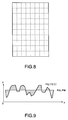
- the movement of the bill image data is performed by the rotation and movement obtained by vector calculation (affine transformation) so that the correction of the oblique lines and the movement of the image data to the origin will be started (Step S1002). Therefore, the bill image data of a vertex at which the image of bill is started is stored at the memory position which becomes the origin in a memory device. Then, for the data of the bill region, as shown in FIG.8, an image region with a size of horizontal direction; 2 [mm] and vertical direction; 4 [mm], for example, (2 pixels ⁇ 4 pixels) is taken to be 1 block.
- a maximum of 48 ⁇ 48 block regions are reserved on a memory device, and the data of the bill are converted to block values and stored therein (Step S1003).
- Pre-processing is performed by making a calculation in accordance with the following equation (9) in order to obtain an average block value; avg_img over the entire region of the block value; img[i][j] after the affine transformation and blocking of the corrected pixel value Crn of coordinates (i, j) shown in FIG.9.
- the average value of the bill image block portions is obtained by dividing the sum total of each block value img[i][j] by the total number of blocks.
- avg_img i-0 Y-1 j-0 X-1 img[i][j]/Y ⁇ X
- Y and X represent the number of blocks in the y- and x-directions of the image obtained by correction of oblique lines.
- the average rate or distance avg_dis of the absolute value of the deviation from the average value of each block is obtained by calculating the sum total of the absolute value of the difference between each block value; img[i][j] and the average value; avg_img of each block obtained by the equation (9) and then dividing the calculated sum total by the total number of blocks.
- the average distance; avg_dis of the block value; img[i][j] and the distance from the average block value; avg_img, that is, the average of the shaded portions of FIG.9 is calculated according to an equation (10) by employing the average block value avg_img of the equation (9).
- an offset common to respective block values for example, the DC component of an electric circuit is cancelled, and an average of absolute values from an average value of patterns (e.g., an average value of AC components of an electric circuit) is calculated.
- avg_dis i-0 Y-1 j-0 X-1
- Y and X represents the number of blocks in the y- and x-directions of the image obtained by correction of oblique lines.
- each block value; img[i][j] is normalized by dividing a deviation value, i.e., the average block value; avg_img subtracted from each block value; img[i][j] by the average block value; avg_img. Then, according to the following equation (11), the gain and offset which effect on the bill image data are cancelled and the normalized block value; NB[i][j] is obtained.
- NB[i][j] ⁇ img[i][j] - avg_img ⁇ /avg_dis
- "i" represents the block position number 0 to Y - 1 in the y-direction
- "j” represents the block position number 0 to X - 1 in the x-direction
- X and Y represent the number of blocks in the y- and x-directions of the image.
- FIGs.10A to 10C are diagrams for explaining the compression encoding based on the present invention.
- FIG.10A shows a row of the normalized values; NB[i][j] in an x direction after the scanned image data of a plurality of lines of the line sensor 3 are blocked for the bill 1, and if the normalized block values of this row are visually shown, they will become as shown in FIG.10B.
- divided level ranges AR1 through AR4 consisting of four regions are allocated to the above normalized block value; NB[i][j].
- the region where the normalized block value; NB[i][j] exists is taken to be "1" and the region where the normalized block value does not exist is taken to be "0".
- the level ranges are encoded by allocating "0” or "1” in order of the level range AR1 to the level range AR4.
- the level ranges are binary-coded by allocating "1” only to the level range in which the normalized block value exists and "0" to each of the other ranges. For example, when the image data is present in the level range AR2, "0100" is obtained. Therefore, as shown in FIG.10C, the level of the normalized block value of each block can be expressed with 4-bit code. The bit position indicates the level range.
- compression processing including the compression (compaction) of the number of steps (processing time) which is performed by the DSP 100, is performed by putting together 8 blocks each having a code train of 4 bits and handling a code train of 32 bits as 1 word.
- the level ranges AR1 through AR 4 are values stored in the flash memory 13 by previously determining an optimum range with external simulation.
- Step S1005 The compression-coded word value is called the cluster value and expressed by CS[i][k].
- RG[i][k] CS[i][k] ⁇ RC[i][k] ⁇
- "i" represents the cluster position number 0 to Y - 1 in the y-direction (the same as the block position)
- "k” represents the cluster positions 0 to (X - 1)/8 and there are units in the x-direction
- X and Y represent the number of blocks in the y- and x-directions and a unit is made of 8 blocks.
- the above equation (12) is an equation for explaining the comparison of a reference code pattern train, stored in the flash memory 13 by tabling it in each direction of the denomination of the bill which is a discrimination candidate at an evaluating position, with a 1 cluster.
- the AND (logical product) is taken between the cluster value CS[i][k] and NOT (negation) of a reference coded cluster value RC[i][k] to be described later, and for the all data from a sheet of bill, if the result of the logical product is other than "0", the judgment result is taken to be "1", and if the result is "0", the judgment result is taken to be "0".
- the clusters where the judgment result at that position is "1" are totaled and stored on an evaluation value table.
- Step S1006 This processing is performed for all of the paper money types and directions of the bill, as a candidate for judgment exclusive of US dollars (Step S1006). Thereafter, the evaluation table is retrieved to select the paper money type (direction) whose evaluation value is a minimum (Step S1007), and it is judged if the minimum evaluation value, which is minimum among evaluation values for each paper money type (direction), is within a threshold value (Step S1008).
- Step S1021 If the minimum evaluation value is within the threshold value, the money type will be settled and this procedure will advance to the Step S1021 for authentication judgment. If the minimum evaluation value is outside the threshold value and there is no corresponding paper money type, it will be judged if U.S. dollar bill has been an object of discrimination (Step S1010). If dollar bill is not an object of discrimination, this procedure will return to the beginning (Step S113). If the dollar bill is the object of discrimination, it is judged if sensed data is U.S. size (Step S1011). The reason why only U.S. bill has additional algorithm is that the discrimination accuracy is sensed by extracting and evaluating only the pattern portion of the bill, because printing shift often occurs in the U.S.
- the logic product is not "0"
- an evaluation value is incremented.
- the logic product of 32 bits is taken and the evaluation value in so-called word, where the results are all "0” or other than "0", is obtained. That is, when all are "0", the result of judgment is "0", and in the case other than that, the result of judgment is "1".
- the judgment in one pattern can be understood from the equation of getting the result of judgment of the equation (13).
- the evaluation value of a bill is the added value of "1" or "0" which is the each judgment result of a plurality of cluster values. If the numerical value of the above evaluation value is large, it will indicate that there are a great number of clusters which are inconsistent with each other and also indicate that there is a long distance between a reference pattern and the pattern of a discriminated bill to be discriminated.
- the judgment result being "0” means that the values of 8 blocks of a corresponding region have all been within a region indicated by cluster value; RC[i][k] which is a reference pattern, and the result of judgment being “1” indicates that at least any of corresponding blocks has been away from a reference pattern (paper money type or direction is different, or bill is not an object of discrimination).
- the minimum distance here is referred to as a calculated evaluation value of a discriminated bill which is smallest among the evaluation values each obtained by adding "1" if the result of each block calculated by the logic operation of the equation (12) is not "0".
- the evaluation values are comprised of the total number of blocks each having "1".
- the operation of the aforementioned equation (12) is executed for all types of paper money to be discriminated, and if the evaluation value is smallest as described above and less than a predetermined threshold, the classification result (i.e., paper money type and direction of the evaluated bill) will be outputted as the discrimination result.
- Step S1012 the pattern portion is first extracted (Step S1012).
- the affine transformation (Step S1013), the blocking (Step S1014), the pre-processing (Step S1015), and the compression and encoding (Step S1016) are executed, and the evaluation values are stored in sequence (Step S1017) on the evaluation table which is provided for each object of the discrimination candidates where no arithmetic operation for the evaluation is performed.
- the minimum evaluation value is retrieved and it is judged if the corresponding paper money type candidate is present, based on whether or not the evaluation value is less than a predetermined threshold (Step S1020). If the corresponding paper money type is not present within dollar bill values, this procedure will return. If the corresponding paper money type is present, the authentical discrimination processing is executed based on the data of the paper money type (Step S1021).
- Step S200 the learning process in the Step S200 is executed according to a flow chart shown in FIG.11.
- Code pattern arrangement CS which is compression-coded are prepared for a plurality of sheets, and a reference code pattern arrangement RC of each discrimination object of paper money type is created according to the OR (logical sum) operation expressed by the equation (13).
- RC[i][k] RC[i][k] ⁇ CS[l][i][k]
- "i” represents the block positions 0 to Y - 1 in the y-direction
- "k” represents the cluster positions 0 to (X - 1)/8 and there are 8-block units in the x-direction
- X and Y represent the number of blocks in the y- and x-directions and a unit is made of 8 blocks.
- a cluster value; RC which is a reference code pattern is created for each paper money type direction. That is, a logical sum is taken between the cluster value; CS[i][k] obtained by blocking data in the same direction for the bill of the same paper money type and the cluster value; RC[i][k] stored when the sheet of one kind of banknotes before is learned, and the logical sum is updated as a new cluster value; RC[i][k].
- the range of the block value sometimes fluctuates due to various fluctuations of regular bill, this is allowed as a reference code pattern. Then, the reference code pattern RC is written in the flash memory 13.
- Step S201 an instruction for the new learning of the n-th pattern (paper money type and direction) or additional learning is received from the host CPU. Then, it is judged if the instruction is an instruction for the additional learning (Step S201). In the case of new learning, a storage region for the n-th pattern learning result is cleared (Step S202). Thereafter, at the aforementioned Step S201, when it is judged that the instruction is the instruction for the additional learning, by the passage sensor 7 it is judged if coming of bill is sensed (Step S203). When the bill has not passed, it is judged if a learning end command is present (Step S204).
- Step S205 If the learning end command is present, the n-th reference code pattern is written in the flash memory 13, and this procedure will return and end (Step S205). If the learning end command is not present at the Step S204, this procedure returns to the aforementioned Step S203. Also, if coming of the bill is sensed at the aforementioned Step S203, it is judged if the received instruction is one which has specified U.S. dolloar bill (Step S210). In the case of the U.S. dollar bill, the patterns of the bill are extracted (Step S212). If the received instruction is not one for the U.S. dollar bill, similar edge extraction as the aforementioned is performed (Step S211).
- Step S23 affine transformation
- Step S214 a logical sum is taken between a cluster value; CS[i][k] obtained by blocking, compression and encoding and a cluster value of the same block of 1 sample sheet before obtained according to the equation (13), and the logical sum is updated as the cluster value; RC[i][k] of a new reference code pattern.
- This operation is performed for the clusters of the entire surface of the bill (Step S215), and this procedure returns to the aforementioned Step S203.
- the compression code pattern distance calculation method employed in the present invention is advantageous in that the encoding bits for expressing each blocked image data with the minimum number of bits are used for bill discrimination. That is, if the pixel value of a corresponding block is normalized so as to be universal and is expressed with less code bits (actually, it is expressed with a digital value consisting of "0" and "1"), the compressibility will be high. In addition, the discrimination time will be shortened and the memory size will be reduced. Therefore, the length of the code bit which is enable to discriminate a paper money is determined whether the identification is possible if a code bit has. Also, it is determined what range each code requires to extract features. By executing the simulation for the discrimination simulation, 4 bits have been determined. The example is shown in FIG.12.
- a part (A) in FIG.12 shows a bill, and the patterns after the compression encoding of the image data of the pattern portion become "0001 0001 0001 0010 ...," as shown in (B).
- the reference code pattern has 4 types, an A-pattern through a D-pattern, because images in four directions exist with respect to one type of bill.
- the A-pattern is "0", and the discrimination result indicates that the evaluation value of the A-pattern is smallest (similar).
- the aforementioned arithmetic operation is executed for the entire region of bill, and if a pattern is a pattern whose evaluation value is small and the evaluation value is less than a predetermined value, the evaluation value is outputted as the discrimination result.
- the discrimination method according to the present invention can reduce the size of a memory device that is used for each paper money type being discriminated, so discrimination of multiple patterns and money type discrimination at a high speed are possible. While this embodiment has been described with reference to bill, the present invention is likewise applicable to paper sheets such as checks.
Abstract
Description
- The present invention relates to a paper note discrimination method which facilitates the identification processing by efficiently compressing and encoding the image data of paper notes such as bill (paper money) and checks when discriminating the paper notes.
- In bill discrimination machines equipped with an image line sensor for collecting the image data of the entire surface of a bill and performing the bill discrimination, in the case where an attempt is made to discriminate not only three types of Japanese bill but also foreign bill at the same time, there is a bill discrimination machine where reference image data usually called a template is prepared and where the reference image data and the image data of another bill to be discriminated are compared to judge paper money type, direction of transport, and authenticity.
- However, in such a conventional general discrimination method, the data of a minute area is processed to perform an accurate identification, as described for example in Japanese Patent Laid-Open No. 260187/1992. Also, in the case where optical data is employed, it is conditioned in many cases that the value of the optical data does not exceed the upper limit of a reference value and has been greater than the lower limit of the reference value. In addition, since in the bill a large quantity of data are processed, there are many cases where an image area predetermined for each type of paper money is specified to raise a processing speed and where the features of only that area are extracted to judge the paper money type or the like.
- In the aforementioned discrimination methods, in the case where the number of types of the bill to be handled is increased, the respective specified areas are different and there is the need to find out the specified area for each bill, so there is the problem that the time for development to find out specified area for each bill is required. Also, resolving the image data into multiple values has become one of the main causes which lengthen the processing time. Furthermore, in the case where there is the need to discriminate a varieties of bill with the same discrimination machine, there is a desire for paper notes discrimination method which reduces a requisite memory size and yet can perform the bill discrimination at a high speed.
- The present invention has been made in view of the aforementioned circumstances, and an object of the present invention is to provide a discrimination method which discriminates denomination for bill at a high speed, while reducing a memory size and data quantity by performing efficient data compression encoding. Another object of the present invention is to provide a discrimination method where addition or change of new paper money type to be discriminated is possible so that learning can be performed in a short time even in the case where the discrimination of unregistered bill is added or the case where new banknote was issued, by learning a reference encoding pattern for discrimination at the same time.
- The present invention relates to a discrimination method used for discriminating paper notes, and the aforementioned objects are achieved by a method of discriminating a paper notes, comprising the steps of: receiving reflected light or transmitted light from the paper note by an image sensor and storing the image data in a memory device; cutting out a region of said paper note from the image data in said memory device; pre-processing the cut-out paper note data to divide it into blocks; compression-encoding the pre-processed data for each block to form pattern data; and comparing the compression-coded pattern data with prestored paper note pattern data to discriminate said paper note.
- In addition, it is performed whether the level of said image data corresponds to which level of predetermined divided levels, by a binary compression-encoding process where a value of "1" or "0" represents a divided level. Therefore, the aforementioned objects can be more effectively achieved. By obtaining reference paper note pattern data by a learning process, new paper notes can be quickly added or changed.
- In the accompanying drawings:
- FIG.1 is a block diagram to show an example of a bill discrimination apparatus of the present invention;
- FIG.2 is a block diagram to show the details of an image processing judgment section in FIG.1;
- FIG.3 is a flow chart to show an example of the entire operation of the present invention;
- FIG.4 is a flow chart showing an example of the discriminating operation of the present invention;
- FIG.5 is part of a flow chart to show an example of the bill discriminating operation of the present invention;
- FIG.6 is part of a flow chart to show an example of the bill discriminating operation of the present invention;
- FIG.7 is a diagram for explaining the edge extraction of bill;
- FIG.8 is a diagram to show an example of the blocking operation of a bill;
- FIG.9 is a diagram for explaining the preprocessing of the image data of the present invention;
- FIGs.10A to 10C are diagrams for explaining the compression encoding of the image data of the present invention;
- FIG.11 is a flow chart to show an example of the learning operation of the present invention; and
- FIG.12 is a diagram for explaining an embodiment of the present invention.
- In bill discrimination machines for discriminating a wide variety of currency denominations in many countries, if the amount of discriminating data which becomes a reference for the comparison becomes smaller by reducing the amount of data to be handled and the time required for discrimination per paper money type will be reduced. Reducing data size is required necessarily for quickly performing the processing. The present invention, in the bill discrimination machines to which 15 sheets of bill per second are conveyed, provides a discrimination method which achieves simultaneous discrimination of 304 patterns (76 paper money types and four directions) while sampling the image data of the entire surface of the bill.
- A preferred embodiment of the present invention will hereinafter be described in detail based on the drawings.
- FIG.1 shows an example of a bill discrimination apparatus for carrying out a discrimination method of the present invention. A
bill 1 is conveyed through the under surface passageway of asensor module 4, which is formed integrally with light emitting means 2 consisting of a light emitting diode array and with aline sensor 3 as light receiving means for receiving the light reflected from thebill 1. The analog video signal VSA from theline sensor 3 is converted to a 8-bit digital video signal VSB by an A/D converter 5 and is inputted to an image processing/judgment section 10. The details of the image processing/judgment section 10 are as shown in FIG.2. - In the image processing/
judgment section 10, the video signal VSB is accumulated in a FIFO (First-In First-Out)memory 11 and also is sequentially transferred and written to a selected region of a main memory (double buffers) 12 via the correctingsection 101 in a digital signal processor (DSP) 100. The DSP 100 cooperates with aROM 110 in which control programs are stored to develope the image data of the amount of a bill in themain memory 12. The DSP 100 has a blocking andcompression encoding section 102 which blocks and compression-encodes the video signal VSB which is inputted via theFIFO memory 11, and also has a comparison/judgment control section 103 which outputs a judgment result DR. Also, the image processing/judgment section 10 has aflash memory 13 for reference-code pattern in which the reference-code patterns for various bills are stored. The reference-code pattern RC and the compressed and encoded data CS of a discriminated bill which is from a part of themain memory 12 are compared at the comparison/judgment control section 103, and the judgment result DR is outputted. The image processing/judgment section 10 performs data communication with adiscriminator control section 20 which controls a discriminator (bill validator) through adual port RAM 14. Note that theflash memory 13 is an electrically rewritable read-only memory and that themain memory 12 functions as double buffers and is a RAM having an image data memory, a work area memory, etc. - Furthermore, the image processing/
judgment section 10 has areading control section 15. Thereading control section 15 performs the on-and-off control of the light emitting means 2, receives a mechanical clock signal ES from arotary encoder 6 used for determining the scanning interval of theline sensor 3 when thebill 1 is conveyed, performs the read-out control of the A/D converter 5, performs the data write-in control of theFIFO memory 11, and generates a read control timing RT of theline sensor 3. On the conveying path for thebill 1, apassage sensor 7 for sensing passage of thebill 1 and an authentication (detects genuine or counterfeit note)sensor 8 for sensing genuin or counterfeit bill are installed. The passage signal PS from thepassage sensor 7 is inputted to thereading control section 15 within the image processing/judgment section 10 and also is inputted to thediscriminator control section 20. The sensed signal from theauthentication sensor 8 is also inputted to thediscriminator control section 20. Thediscriminator control section 20 is connected to the image processing/judgment section 10 and also is connected to the main body control section (e.g., upper device controller) 30 such as a bill payment processor. - FIG.3 is a flow chart to show the operation example of the
DSP 100 within the image processing/judgment section 10 in FIGs.1 and 2. First, the initialization required for hardware, such as a bill conveying mechanism, is performed (Step S1), and it is checked if there is nothing abnormal in the state of the hardware (Step S2). Thereafter, the hardware is put in a mechanical-command waiting state. If the mechanical-command is inputted and a start of the operation is instructed by a host CPU which is in the discriminator control section 20 (Step S3), it is judged whether the command is a start of discrimination or not (Step S6). In the case of the discrimination, the discrimination is performed (Step S100). When it is not the discrimination command at the Step S6, it is judged whether it is a start of learning or not (Step S7). In the case of the learning, the learning is performed (Step S200). When it is not the start of the learning at the Step S7, it is judged if it is the setting of RAS mode which is the mode that can run a special program created for test or evaluation (Step S8). In the case of the setting of the RAS mode, various RAS commands are processed (Step S9). "RAS" is an abbreviation of "Reliability, Availability and Serviceability". In the case where the command is not the setting of the RAS mode in the aforementioned Step S8, the Step S9 returns to the aforementioned Step S3 after various commands. are processed. Also, the Step S200 and Step S100 return to the aforementioned Step S3 after the learning is processed and after the identification is processed, respectively. - FIG.4 is a flow chart to show an example of the detailed operation of the aforementioned discriminating process (Step S100). If the discriminating process is started, black level data, which is dark-time output data, is collected (Step S101) by reading out the output of the
line sensor 3 in the state when the LED of the light emitting means 2 is turned off, in order to first collect the output of theline sensor 3. Thereafter, the light emitting means 2 is turned on (Step S102), and sending of a mechanical response is executed (Step S103) by writing a discrimination preparation completion response to thedual port RAM 14 and generating an interruption to inform to the host CPU. Next, if a passage of thebill 1 is sensed by thepassage sensor 7, the passage signal PS on arrival of the bill sets thereading control section 15 in active (Step S104), and the video signal VSA from theline sensor 3 is converted from its analog value to a digital value VSB by the A/D converter 5 and the digital value VSB is written in theFIFO memory 11. Thereafter, the video digital signal VSB is corrected by the correctingsection 101 in theDSP 100, and the result is written in one of the double buffers of themain memory 12. Theline sensor 3 performs collection of the image data (Step S110), while the correction is being executed in the correctingsection 101 by using the black level data fetched and processed when the discrimination is started and also using the white level data and black level data which have been written in theflash memory 13 by previously executing a program. - When the collection of the data of a sheet of image is completed, the double buffers will be switched (Step S111). That is, one buffer which is the data collected region of the
main memory 12 is switched to a discriminating region, and the other buffer where the discrimination has been completed is switched to a data correlating region for the bill to be discriminated next. Permission of this switching is executed by enabling an interruption of thepassage sensor 7. With this, the double buffers are put in a data collection stand-by state (Step S112) for the bill to be discriminated next. Based on the collected data, the bill discrimination shown in detail in FIGs.5 and 6 is performed (Step S1000), and a discrimination result DR is sent out from the comparison/judgment control section 103 (Step S113). The above sending of the result DR is performed by wiring the result to thedual port RAM 14 and generating a response interruption to inform to the host CPU. Also, when the passing out of thebill 1 is not sensed at the aforementioned Step S104, it is judged if there is an end command (Step S120). If there is no end command, the Step 120 will return to the aforementioned Step S104, and if there is the end command, a discrimination end response will be sent out (Step S121). The light emitting means 2 is turned off (Step S122), and the Step S122 returns to the Step S3 in FIG.3. - Note that the aforementioned correction of the analog video signal VSB which is fetched from the
line sensor 3 and stored in themain memory 12, is performed in theDSP 100 as follows. A black level is work out with both (1) the data previously stored and prepared in theflash memory 13 by executing an additionally provided RAS command and (2) the data taken in by running a data acquiring program by turning off the light emitting means 2 when the discrimination is started. A white level is work out with the data previously stored and prepared in theflash memory 13 by executing the additionally provided RAS command. Predetermined white paper is attached to the front face of thesensor module 4, and the data collection program specified by the RAS is executed. The output of theline sensor 3 at that time is taken in, and the aforementioned black level and white level correction data are processed by averaging a plurality of outputs of the same channel with theDSP 100. The processed data is written in theflash memory 13 by theDSP 100. At the time of the discrimination, an arithmetic operation is performed for each pixel In with the following equation (1), based on the correction data written in theflash memory 13, and the corrected pixel value CRn of the corrected n-th pixel is obtained.
- G:
- Data of the first bit of each line, that is, a gain G determined by both the data of received light due to the reflection from white tape and the data of the first bit due to the reflection from the white tape stored in the
flash memory 13. On the 1 through 5 channels of theline sensor 3, a reference white tape is attached in a corner of thesensor module 4 so that a quantity of light can be corrected. The gain G is set so that the A/D value of the output of theline sensor 3 at the time of the initialization in assembly and the A/D value of the present output of theline sensor 3 become equal to each other. Also, the term "(165/(Wn - Bn)) × (In - BKn)" is used to compensate the fluctuations in a voltage representative of the correction between channels of theline sensor 3, in environment such as temperature, and in a specular change. - Wn:
- Average value of several sampling results of the white level of the n-th channel. This value is stored in the
flash memory 13. - Bn:
- Average value of several sampling results of the black level of the n-th channel. This value is stored in the
flash memory 13. - BKn:
- Average value of several lines (several scans) of the black level of the n-th channel collected in the state when the light emitting means 2 is turned off at the time of the discrimination start.
- In:
- Image data of a discriminate bill of the n-th channel (image data to be corrected), and "n" represents channel Nos. 6 through 95.
- The bill discrimination at the Step S1000 is executed according to the flow charts shown in FIGs.5 and 6. First, the edges of the
bill 1 are extracted (Step S1001). The edge extraction, as shown in FIG.7, is performed by first scanning through the discrimination object bill in directions A and B to extract edges (A-edge and B-edge in the figure), and the left and right edge sides of the bill are obtained according to the following equation (2).
- The above equation (2) is led based on the following reasons. That is, the B-side is scanned in direction X at a predetermined interval Y and a side coordinate (Xbn, Ybn) is obtained. The side coordinate (Xbn, Ybn) is developed (Huff transformation) to a U-V plane in accordance with below equation (3). Scope of V at the development time is determined based on the passage and bill size.


- Similarlly, the A-side is scanned in the direction X at the predetermined interval Y and an edge coordinate (Xan, Yan) is obtained. Since the A-side line is parallel to the B-side line, an inclination a is the same and an intersection for X-axis is obtained. The edge coordinate (Xan, Yan) is substituted for the below equation (5) and an intersection histogram bA2n for the X-axis is obtained.

- The intersections (sub-b1, sub-b2) of the X-axis, where the number of candidates is a maximum with respect to the two lines of the aforementioned equation (2), are obtained by substituting the coordinate values of the A- and B-sides into the following equation (6). The side lines (sides C and D) of the bill in the directions being perpendicular to the lines of equation (2) are expressed by an equation (6).


- From the histogram of y-intersection coordinates obtained by the equation (7), each number of candidates sub_b1 and sub_b2 which is the maximum are determined, and from the equations (2) and (6) the coordinates of each vertex are obtained by the following equation (8).

- After the edges of the
bill 1 are extracted in the aforementioned way, the movement of the bill image data is performed by the rotation and movement obtained by vector calculation (affine transformation) so that the correction of the oblique lines and the movement of the image data to the origin will be started (Step S1002). Therefore, the bill image data of a vertex at which the image of bill is started is stored at the memory position which becomes the origin in a memory device. Then, for the data of the bill region, as shown in FIG.8, an image region with a size of horizontal direction; 2 [mm] and vertical direction; 4 [mm], for example, (2 pixels × 4 pixels) is taken to be 1 block. A maximum of 48 × 48 block regions are reserved on a memory device, and the data of the bill are converted to block values and stored therein (Step S1003). Pre-processing is performed by making a calculation in accordance with the following equation (9) in order to obtain an average block value; avg_img over the entire region of the block value; img[i][j] after the affine transformation and blocking of the corrected pixel value Crn of coordinates (i, j) shown in FIG.9. The coordinate position of the block is (y = i, x = j) where "i" is the final vertical block coordinate (Y - 1) determined by i = 1 to bill size and "j" is the final horizontal block coordinate (X - 1) determined by j = 1 to bill size (Step S1004). The average value of the bill image block portions is obtained by dividing the sum total of each block value img[i][j] by the total number of blocks.
- Next, the average rate or distance avg_dis of the absolute value of the deviation from the average value of each block is obtained by calculating the sum total of the absolute value of the difference between each block value; img[i][j] and the average value; avg_img of each block obtained by the equation (9) and then dividing the calculated sum total by the total number of blocks. Next, the average distance; avg_dis of the block value; img[i][j] and the distance from the average block value; avg_img, that is, the average of the shaded portions of FIG.9 is calculated according to an equation (10) by employing the average block value avg_img of the equation (9). With this, an offset common to respective block values, for example, the DC component of an electric circuit is cancelled, and an average of absolute values from an average value of patterns (e.g., an average value of AC components of an electric circuit) is calculated.

- Next, each block value; img[i][j] is normalized by dividing a deviation value, i.e., the average block value; avg_img subtracted from each block value; img[i][j] by the average block value; avg_img. Then, according to the following equation (11), the gain and offset which effect on the bill image data are cancelled and the normalized block value; NB[i][j] is obtained.

block position number 0 to Y - 1 in the y-direction, "j" represents theblock position number 0 to X - 1 in the x-direction, and X and Y represent the number of blocks in the y- and x-directions of the image. - If the pre-processing ends in the aforementioned way, the pre-processed normalized block value; NB[i][j] will be compressed and encoded (Step S1005). FIGs.10A to 10C are diagrams for explaining the compression encoding based on the present invention. FIG.10A shows a row of the normalized values; NB[i][j] in an x direction after the scanned image data of a plurality of lines of the
line sensor 3 are blocked for thebill 1, and if the normalized block values of this row are visually shown, they will become as shown in FIG.10B. In the present invention, divided level ranges AR1 through AR4 consisting of four regions are allocated to the above normalized block value; NB[i][j]. Among the level ranges AR1 through AR4, the region where the normalized block value; NB[i][j] exists is taken to be "1" and the region where the normalized block value does not exist is taken to be "0". The level ranges are encoded by allocating "0" or "1" in order of the level range AR1 to the level range AR4. As a result, the level ranges are binary-coded by allocating "1" only to the level range in which the normalized block value exists and "0" to each of the other ranges. For example, when the image data is present in the level range AR2, "0100" is obtained. Therefore, as shown in FIG.10C, the level of the normalized block value of each block can be expressed with 4-bit code. The bit position indicates the level range. - Therefore, the data of 1-pixel of 256-gray levels expressed with 8 bits, fetched from the A/
D converter 5, is blocked into a block of 2 × 4 and compression-coded to a 4-gray level expressed by 4 bits. Thereafter, compression processing, including the compression (compaction) of the number of steps (processing time) which is performed by theDSP 100, is performed by putting together 8 blocks each having a code train of 4 bits and handling a code train of 32 bits as 1 word. Here, the level ranges AR1 throughAR 4 are values stored in theflash memory 13 by previously determining an optimum range with external simulation. - In the aforementioned way, the compression encoding of each normalized block processed from the image data is ended (Step S1005). The compression-coded word value is called the cluster value and expressed by CS[i][k]. Here, a relation of k = j/8 (only the quotient of division is applied to k) is established.

cluster position number 0 to Y - 1 in the y-direction (the same as the block position), "k" represents thecluster positions 0 to (X - 1)/8 and there are units in the x-direction, and X and Y represent the number of blocks in the y- and x-directions and a unit is made of 8 blocks. - The above equation (12) is an equation for explaining the comparison of a reference code pattern train, stored in the
flash memory 13 by tabling it in each direction of the denomination of the bill which is a discrimination candidate at an evaluating position, with a 1 cluster. The AND (logical product) is taken between the cluster value CS[i][k] and NOT (negation) of a reference coded cluster value RC[i][k] to be described later, and for the all data from a sheet of bill, if the result of the logical product is other than "0", the judgment result is taken to be "1", and if the result is "0", the judgment result is taken to be "0". The clusters where the judgment result at that position is "1" are totaled and stored on an evaluation value table. This processing is performed for all of the paper money types and directions of the bill, as a candidate for judgment exclusive of US dollars (Step S1006). Thereafter, the evaluation table is retrieved to select the paper money type (direction) whose evaluation value is a minimum (Step S1007), and it is judged if the minimum evaluation value, which is minimum among evaluation values for each paper money type (direction), is within a threshold value (Step S1008). - If the minimum evaluation value is within the threshold value, the money type will be settled and this procedure will advance to the Step S1021 for authentication judgment. If the minimum evaluation value is outside the threshold value and there is no corresponding paper money type, it will be judged if U.S. dollar bill has been an object of discrimination (Step S1010). If dollar bill is not an object of discrimination, this procedure will return to the beginning (Step S113). If the dollar bill is the object of discrimination, it is judged if sensed data is U.S. size (Step S1011). The reason why only U.S. bill has additional algorithm is that the discrimination accuracy is sensed by extracting and evaluating only the pattern portion of the bill, because printing shift often occurs in the U.S. dollars and also similar patterns among different denominations of U.S. dollar exist. Furthermore, in the
DSP DSP 100 so that the operating speed is raised. - In the discrimination processing of whether a type of paper money is a desired type, a one array between a cluster value CS which is a coded pattern array of all compression-coded, normalized blocks and a corresponding negated value of a cluster value RC which is a reference code pattern array of all normalized blocks within the
main memory 12 obtained by a learning process (to be described later), that is, the logical product of 32 bits (logical product of 8 blocks in the original blocked value) is taken. When the logic product is not "0", an evaluation value is incremented. The logic product of 32 bits is taken and the evaluation value in so-called word, where the results are all "0" or other than "0", is obtained. That is, when all are "0", the result of judgment is "0", and in the case other than that, the result of judgment is "1". The judgment in one pattern can be understood from the equation of getting the result of judgment of the equation (13). - The evaluation value of a bill is the added value of "1" or "0" which is the each judgment result of a plurality of cluster values. If the numerical value of the above evaluation value is large, it will indicate that there are a great number of clusters which are inconsistent with each other and also indicate that there is a long distance between a reference pattern and the pattern of a discriminated bill to be discriminated. Here, the judgment result being "0" means that the values of 8 blocks of a corresponding region have all been within a region indicated by cluster value; RC[i][k] which is a reference pattern, and the result of judgment being "1" indicates that at least any of corresponding blocks has been away from a reference pattern (paper money type or direction is different, or bill is not an object of discrimination). The minimum distance here is referred to as a calculated evaluation value of a discriminated bill which is smallest among the evaluation values each obtained by adding "1" if the result of each block calculated by the logic operation of the equation (12) is not "0". The evaluation values are comprised of the total number of blocks each having "1". The operation of the aforementioned equation (12) is executed for all types of paper money to be discriminated, and if the evaluation value is smallest as described above and less than a predetermined threshold, the classification result (i.e., paper money type and direction of the evaluated bill) will be outputted as the discrimination result.
- In the case of the U.S. dollar in the aforementioned Step S1011, the pattern portion is first extracted (Step S1012). As mentioned above, the affine transformation (Step S1013), the blocking (Step S1014), the pre-processing (Step S1015), and the compression and encoding (Step S1016) are executed, and the evaluation values are stored in sequence (Step S1017) on the evaluation table which is provided for each object of the discrimination candidates where no arithmetic operation for the evaluation is performed. Then, the minimum evaluation value is retrieved and it is judged if the corresponding paper money type candidate is present, based on whether or not the evaluation value is less than a predetermined threshold (Step S1020). If the corresponding paper money type is not present within dollar bill values, this procedure will return. If the corresponding paper money type is present, the authentical discrimination processing is executed based on the data of the paper money type (Step S1021).
- On the other hand, the learning process in the Step S200 is executed according to a flow chart shown in FIG.11. Code pattern arrangement CS which is compression-coded are prepared for a plurality of sheets, and a reference code pattern arrangement RC of each discrimination object of paper money type is created according to the OR (logical sum) operation expressed by the equation (13).

block positions 0 to Y - 1 in the y-direction, "k" represents thecluster positions 0 to (X - 1)/8 and there are 8-block units in the x-direction, and X and Y represent the number of blocks in the y- and x-directions and a unit is made of 8 blocks. - By the learning process based on the aforementioned equation (13), a cluster value; RC which is a reference code pattern is created for each paper money type direction. That is, a logical sum is taken between the cluster value; CS[i][k] obtained by blocking data in the same direction for the bill of the same paper money type and the cluster value; RC[i][k] stored when the sheet of one kind of banknotes before is learned, and the logical sum is updated as a new cluster value; RC[i][k]. Although the range of the block value sometimes fluctuates due to various fluctuations of regular bill, this is allowed as a reference code pattern. Then, the reference code pattern RC is written in the
flash memory 13. - In the learning process an instruction for the new learning of the n-th pattern (paper money type and direction) or additional learning is received from the host CPU. Then, it is judged if the instruction is an instruction for the additional learning (Step S201). In the case of new learning, a storage region for the n-th pattern learning result is cleared (Step S202). Thereafter, at the aforementioned Step S201, when it is judged that the instruction is the instruction for the additional learning, by the
passage sensor 7 it is judged if coming of bill is sensed (Step S203). When the bill has not passed, it is judged if a learning end command is present (Step S204). If the learning end command is present, the n-th reference code pattern is written in theflash memory 13, and this procedure will return and end (Step S205). If the learning end command is not present at the Step S204, this procedure returns to the aforementioned Step S203. Also, if coming of the bill is sensed at the aforementioned Step S203, it is judged if the received instruction is one which has specified U.S. dolloar bill (Step S210). In the case of the U.S. dollar bill, the patterns of the bill are extracted (Step S212). If the received instruction is not one for the U.S. dollar bill, similar edge extraction as the aforementioned is performed (Step S211). Thereafter, the affine transformation (Step S213) and the pre-processing, such as the correction of oblique lines and the last movement of the image data are executed (Step S214). With the processing at the time of the discrimination described by employing FIGs.5 and 6, a logical sum is taken between a cluster value; CS[i][k] obtained by blocking, compression and encoding and a cluster value of the same block of 1 sample sheet before obtained according to the equation (13), and the logical sum is updated as the cluster value; RC[i][k] of a new reference code pattern. This operation is performed for the clusters of the entire surface of the bill (Step S215), and this procedure returns to the aforementioned Step S203. - In the learning process, by expressing 1 block value with 4 bits and performing the learning based on a logical sum, the range of the block value of the bill, which should be a regular reference, can be easily learned. In addition, since a block value that is handled is normalized, it is immune to the fluctuation dependent upon the hardware of the bill balidator, a change with the lapse of time and environmental change.
- The compression code pattern distance calculation method employed in the present invention is advantageous in that the encoding bits for expressing each blocked image data with the minimum number of bits are used for bill discrimination. That is, if the pixel value of a corresponding block is normalized so as to be universal and is expressed with less code bits (actually, it is expressed with a digital value consisting of "0" and "1"), the compressibility will be high. In addition, the discrimination time will be shortened and the memory size will be reduced. Therefore, the length of the code bit which is enable to discriminate a paper money is determined whether the identification is possible if a code bit has. Also, it is determined what range each code requires to extract features. By executing the simulation for the discrimination simulation, 4 bits have been determined. The example is shown in FIG.12. A part (A) in FIG.12 shows a bill, and the patterns after the compression encoding of the image data of the pattern portion become "0001 0001 0001 0010 ...," as shown in (B). The reference code pattern has 4 types, an A-pattern through a D-pattern, because images in four directions exist with respect to one type of bill. For an evaluation value (C) in FIG.12, the A-pattern is "0", and the discrimination result indicates that the evaluation value of the A-pattern is smallest (similar). The aforementioned arithmetic operation is executed for the entire region of bill, and if a pattern is a pattern whose evaluation value is small and the evaluation value is less than a predetermined value, the evaluation value is outputted as the discrimination result.
- As has been described above, the discrimination method according to the present invention can reduce the size of a memory device that is used for each paper money type being discriminated, so discrimination of multiple patterns and money type discrimination at a high speed are possible. While this embodiment has been described with reference to bill, the present invention is likewise applicable to paper sheets such as checks.
Claims (14)
- A method of discriminating a paper note, comprising the steps of:receiving reflected light or transmitted light from the paper note by an image sensor and storing image data in a memory device;cutting out a region of said paper note from the image data of said memory device;pre-processing the cut-out paper note image data to divide it into blocks;compression-encoding from the pre-processed data of each block into form pattern data; andcomparing the compression-coded pattern data with prestored paper note pattern data as reference pattern data to discriminate said paper note.
- A discrimination method as set forth in Claim 1, wherein in said compression-encoding, it is performed whether the level of said pre-processed block data corresponds to which level of predetermined dividing levels, by a binary method where a value of 1 or 0 is given to a value whether a bit position which is caused to correspond to the dividing level or not.
- A discrimination method as set forth in Claim 1 or 2 further including the steps of a learning and an RAS commond process.
- A discrimination method as set forth in any of Claims 1 to 3, wherein in the comparing step, a logical product is taken between said compression coded pattern data and a logically negated value of said reference pattern data for each unit consisting of a plurality of blocks, and the number of the units where the result which is other than "0" is counted for a sheet of paper note and is stored, and wherein the comparison of the compression coded pattern data with said reference pattern data is executed only for a reference pattern of discrimination, where the stored number is minimum and less than a predetermined number, are the discrimination results of a corresponding paper note.
- A discrimination method as set forth in any of Claims 1 to 4, wherein said reference pattern data of the paper note is stored in a flash memory.
- A discrimination method as set forth in any of Claims 1 to 5, wherein said memory device functions as double buffers and has at least an image data memory and a working area memory.
- A discrimination method as set forth in any of Claims 1 to 6, wherein in said reference pattern data, a logical sum of compression coded data of a paper note which become an object having an output as a discrimination result is sequentially taken, and is stored as a reference pattern data of said paper note.
- A discrimination method as set forth in any of Claims 1 to 7, wherein said blocking process is performed by extracting edges of said paper note and calculating vectors with an affine transformation.
- A discrimination method as set forth in any of Claims 1 to 8, wherein said pre-processing is performed by obtaining an average block value over an entire region of each block value of image of paper notes after the blocking operation.
- A discrimination method as set forth in Claim 9 further including the steps of obtaining a sum total of an absolute value of a difference between said each block value and said average block value and obtaining an absolute average distance by dividing said calculated sum total by a total number of said blocks.
- A discrimination method as set forth in Claim 10 including the steps of normalizing said each block value by dividing a deviation value which subtracted said average block value from said each block value, by said absolute average distance.
- A discrimination method as set forth in any of Claims 2 to 11, wherein a cluster value is allotted to a word value obtained by said binary method and reference cluster values encoded for said paper note are previously stored in a memory means.
- A discrimination method as set forth in any of Claims 2 to 12, wherein said dividing levels are 4 and said block value is expressed by 4 bits.
- A discrimination method as set forth in any of Claims 4 to 13, a number of said counted units is stored in an evaluation table as an evaluation value and said evaluation table is updated at every discrimination of a sheet of paper note.
Applications Claiming Priority (3)
| Application Number | Priority Date | Filing Date | Title |
|---|---|---|---|
| JP11524596 | 1996-04-15 | ||
| JP11524596A JP3741777B2 (en) | 1996-04-15 | 1996-04-15 | Paper sheet identification method |
| JP115245/96 | 1996-04-15 |
Publications (3)
| Publication Number | Publication Date |
|---|---|
| EP0802510A2 true EP0802510A2 (en) | 1997-10-22 |
| EP0802510A3 EP0802510A3 (en) | 1999-02-03 |
| EP0802510B1 EP0802510B1 (en) | 2004-08-04 |
Family
ID=14657942
Family Applications (1)
| Application Number | Title | Priority Date | Filing Date |
|---|---|---|---|
| EP97106101A Expired - Lifetime EP0802510B1 (en) | 1996-04-15 | 1997-04-14 | Method of discriminating paper notes |
Country Status (6)
| Country | Link |
|---|---|
| US (1) | US5947255A (en) |
| EP (1) | EP0802510B1 (en) |
| JP (1) | JP3741777B2 (en) |
| AT (1) | ATE272876T1 (en) |
| DE (1) | DE69730072T2 (en) |
| ES (1) | ES2223069T3 (en) |
Cited By (6)
| Publication number | Priority date | Publication date | Assignee | Title |
|---|---|---|---|---|
| EP1060453A1 (en) * | 1998-02-12 | 2000-12-20 | Cummins-Allison Corporation | Software loading system for an automatic funds processing system |
| ES2293750A1 (en) * | 1999-08-04 | 2008-03-16 | Fujitsu Limited | Paper sheet judging device and judging control method |
| EP1927937A3 (en) * | 2006-12-01 | 2009-07-29 | NEC Corporation | Certificate stamp identifying system and certificate stamp identifying method |
| DE102008051758A1 (en) * | 2008-10-15 | 2010-04-22 | Giesecke & Devrient Gmbh | Method and device for processing value documents |
| AT508977B1 (en) * | 2009-10-28 | 2011-07-15 | Ait Austrian Inst Technology | BANKNOTE RECOGNITION WITH PROJECTION PROFILE |
| US8417016B2 (en) | 2004-12-15 | 2013-04-09 | Money Controls Limited | Acceptor device for sheet objects |
Families Citing this family (49)
| Publication number | Priority date | Publication date | Assignee | Title |
|---|---|---|---|---|
| US6748101B1 (en) | 1995-05-02 | 2004-06-08 | Cummins-Allison Corp. | Automatic currency processing system |
| US6363164B1 (en) | 1996-05-13 | 2002-03-26 | Cummins-Allison Corp. | Automated document processing system using full image scanning |
| US8950566B2 (en) | 1996-05-13 | 2015-02-10 | Cummins Allison Corp. | Apparatus, system and method for coin exchange |
| US7903863B2 (en) | 2001-09-27 | 2011-03-08 | Cummins-Allison Corp. | Currency bill tracking system |
| US7187795B2 (en) | 2001-09-27 | 2007-03-06 | Cummins-Allison Corp. | Document processing system using full image scanning |
| US20050276458A1 (en) | 2004-05-25 | 2005-12-15 | Cummins-Allison Corp. | Automated document processing system and method using image scanning |
| US8162125B1 (en) | 1996-05-29 | 2012-04-24 | Cummins-Allison Corp. | Apparatus and system for imaging currency bills and financial documents and method for using the same |
| US8478020B1 (en) | 1996-11-27 | 2013-07-02 | Cummins-Allison Corp. | Apparatus and system for imaging currency bills and financial documents and method for using the same |
| US6585341B1 (en) | 1997-06-30 | 2003-07-01 | Hewlett-Packard Company | Back-branding media determination system for inkjet printing |
| US6425650B1 (en) | 1997-06-30 | 2002-07-30 | Hewlett-Packard Company | Educatable media determination system for inkjet printing |
| US6561643B1 (en) | 1997-06-30 | 2003-05-13 | Hewlett-Packard Co. | Advanced media determination system for inkjet printing |
| JPH11355562A (en) * | 1998-06-04 | 1999-12-24 | Omron Corp | Illegal image formation preventing device and image forming device |
| GB2344446A (en) * | 1998-12-02 | 2000-06-07 | Mars Inc | Classifying currency items |
| US6370266B1 (en) * | 1999-04-16 | 2002-04-09 | Ncr Corporation | Financial document processing system and method of operating a financial document processing system to verify zone coordinates |
| US8701857B2 (en) | 2000-02-11 | 2014-04-22 | Cummins-Allison Corp. | System and method for processing currency bills and tickets |
| US7104383B1 (en) * | 2000-02-14 | 2006-09-12 | Leon Saltsov | Validator with removable flash memory |
| SE516421C2 (en) * | 2000-05-16 | 2002-01-15 | Luciano Beghello | Method and apparatus for quality inspection of light-transparent safety elements |
| JP2002288604A (en) * | 2001-03-27 | 2002-10-04 | Topcon Corp | Authenticity determining device of card |
| US7647275B2 (en) | 2001-07-05 | 2010-01-12 | Cummins-Allison Corp. | Automated payment system and method |
| JP2003067805A (en) * | 2001-08-28 | 2003-03-07 | Hitachi Ltd | Device for discriminating truth or falsehood of sheet paper |
| US8944234B1 (en) | 2001-09-27 | 2015-02-03 | Cummins-Allison Corp. | Apparatus and system for imaging currency bills and financial documents and method for using the same |
| US8437530B1 (en) | 2001-09-27 | 2013-05-07 | Cummins-Allison Corp. | Apparatus and system for imaging currency bills and financial documents and method for using the same |
| US8428332B1 (en) | 2001-09-27 | 2013-04-23 | Cummins-Allison Corp. | Apparatus and system for imaging currency bills and financial documents and method for using the same |
| US8433123B1 (en) | 2001-09-27 | 2013-04-30 | Cummins-Allison Corp. | Apparatus and system for imaging currency bills and financial documents and method for using the same |
| US8437529B1 (en) | 2001-09-27 | 2013-05-07 | Cummins-Allison Corp. | Apparatus and system for imaging currency bills and financial documents and method for using the same |
| US6896118B2 (en) | 2002-01-10 | 2005-05-24 | Cummins-Allison Corp. | Coin redemption system |
| KR100661440B1 (en) * | 2002-08-30 | 2006-12-27 | 후지츠 프론테크 가부시키가이샤 | Paper sheets characteristic detection device and paper sheets characteristic detection method |
| CN1653492B (en) * | 2002-08-30 | 2010-05-12 | 富士通株式会社 | Device and method for identifying paper sheet |
| US8171567B1 (en) | 2002-09-04 | 2012-05-01 | Tracer Detection Technology Corp. | Authentication method and system |
| US8627939B1 (en) | 2002-09-25 | 2014-01-14 | Cummins-Allison Corp. | Apparatus and system for imaging currency bills and financial documents and method for using the same |
| US7222712B2 (en) * | 2003-03-24 | 2007-05-29 | Valtech International, Llc | Document validator with locking cassette |
| US7946406B2 (en) | 2005-11-12 | 2011-05-24 | Cummins-Allison Corp. | Coin processing device having a moveable coin receptacle station |
| US7980378B2 (en) | 2006-03-23 | 2011-07-19 | Cummins-Allison Corporation | Systems, apparatus, and methods for currency processing control and redemption |
| US7929749B1 (en) | 2006-09-25 | 2011-04-19 | Cummins-Allison Corp. | System and method for saving statistical data of currency bills in a currency processing device |
| JP5093877B2 (en) | 2006-09-29 | 2012-12-12 | 株式会社ユニバーサルエンターテインメント | Paper sheet identification device |
| US8194236B2 (en) | 2006-09-29 | 2012-06-05 | Universal Entertainment Corporation | Sheet identifying device |
| US8417017B1 (en) | 2007-03-09 | 2013-04-09 | Cummins-Allison Corp. | Apparatus and system for imaging currency bills and financial documents and method for using the same |
| US8538123B1 (en) | 2007-03-09 | 2013-09-17 | Cummins-Allison Corp. | Apparatus and system for imaging currency bills and financial documents and method for using the same |
| CA2677714C (en) | 2007-03-09 | 2014-12-23 | Cummins-Allison Corp. | Document imaging and processing system |
| WO2009072211A1 (en) * | 2007-12-07 | 2009-06-11 | Glory Ltd. | Banknote identifying device and banknote identifying method |
| US20090294243A1 (en) * | 2008-05-30 | 2009-12-03 | Harold Charych | Currency Validator Video Graphic Display Bezel |
| JP5210067B2 (en) * | 2008-07-22 | 2013-06-12 | 株式会社ユニバーサルエンターテインメント | Paper sheet processing equipment |
| US8437528B1 (en) | 2009-04-15 | 2013-05-07 | Cummins-Allison Corp. | Apparatus and system for imaging currency bills and financial documents and method for using the same |
| US8391583B1 (en) | 2009-04-15 | 2013-03-05 | Cummins-Allison Corp. | Apparatus and system for imaging currency bills and financial documents and method for using the same |
| US8929640B1 (en) | 2009-04-15 | 2015-01-06 | Cummins-Allison Corp. | Apparatus and system for imaging currency bills and financial documents and method for using the same |
| US8948489B2 (en) * | 2010-01-12 | 2015-02-03 | Glory Ltd. | Paper sheet recognition device and paper sheet recognition method |
| JP5690668B2 (en) * | 2011-06-24 | 2015-03-25 | 日立オムロンターミナルソリューションズ株式会社 | Automatic transaction device with image trail function |
| US9141876B1 (en) | 2013-02-22 | 2015-09-22 | Cummins-Allison Corp. | Apparatus and system for processing currency bills and financial documents and method for using the same |
| CN103700184B (en) * | 2013-12-23 | 2016-04-06 | 华中科技大学 | The control method of multi-spectral money counting and checking machine machine in multilevel sleep mode |
Citations (6)
| Publication number | Priority date | Publication date | Assignee | Title |
|---|---|---|---|---|
| US4041456A (en) * | 1976-07-30 | 1977-08-09 | Ott David M | Method for verifying the denomination of currency |
| EP0067898A1 (en) * | 1981-06-22 | 1982-12-29 | Kabushiki Kaisha Toshiba | System for identifying currency note |
| US4487306A (en) * | 1981-07-24 | 1984-12-11 | Fujitsu Limited | Bill-discriminating apparatus |
| EP0472192A2 (en) * | 1990-08-22 | 1992-02-26 | Oki Electric Industry Co., Ltd. | Apparatus for and method of discriminating bill |
| WO1994012951A1 (en) * | 1992-11-30 | 1994-06-09 | Mars Incorporated | Method and apparatus for the classification of an article |
| US5363949A (en) * | 1991-12-18 | 1994-11-15 | Nec Corporation | Bill recognizing apparatus |
Family Cites Families (2)
| Publication number | Priority date | Publication date | Assignee | Title |
|---|---|---|---|---|
| GB2250621B (en) * | 1990-12-07 | 1995-04-19 | Mars Inc | Money validators |
| US5737418A (en) * | 1995-05-30 | 1998-04-07 | International Game Technology | Encryption of bill validation data |
-
1996
- 1996-04-15 JP JP11524596A patent/JP3741777B2/en not_active Expired - Fee Related
-
1997
- 1997-04-14 AT AT97106101T patent/ATE272876T1/en not_active IP Right Cessation
- 1997-04-14 ES ES97106101T patent/ES2223069T3/en not_active Expired - Lifetime
- 1997-04-14 DE DE69730072T patent/DE69730072T2/en not_active Expired - Lifetime
- 1997-04-14 EP EP97106101A patent/EP0802510B1/en not_active Expired - Lifetime
- 1997-04-15 US US08/834,210 patent/US5947255A/en not_active Expired - Lifetime
Patent Citations (6)
| Publication number | Priority date | Publication date | Assignee | Title |
|---|---|---|---|---|
| US4041456A (en) * | 1976-07-30 | 1977-08-09 | Ott David M | Method for verifying the denomination of currency |
| EP0067898A1 (en) * | 1981-06-22 | 1982-12-29 | Kabushiki Kaisha Toshiba | System for identifying currency note |
| US4487306A (en) * | 1981-07-24 | 1984-12-11 | Fujitsu Limited | Bill-discriminating apparatus |
| EP0472192A2 (en) * | 1990-08-22 | 1992-02-26 | Oki Electric Industry Co., Ltd. | Apparatus for and method of discriminating bill |
| US5363949A (en) * | 1991-12-18 | 1994-11-15 | Nec Corporation | Bill recognizing apparatus |
| WO1994012951A1 (en) * | 1992-11-30 | 1994-06-09 | Mars Incorporated | Method and apparatus for the classification of an article |
Cited By (8)
| Publication number | Priority date | Publication date | Assignee | Title |
|---|---|---|---|---|
| EP1060453A1 (en) * | 1998-02-12 | 2000-12-20 | Cummins-Allison Corporation | Software loading system for an automatic funds processing system |
| EP1060453A4 (en) * | 1998-02-12 | 2002-02-13 | Cummins Allison Corp | Software loading system for an automatic funds processing system |
| ES2293750A1 (en) * | 1999-08-04 | 2008-03-16 | Fujitsu Limited | Paper sheet judging device and judging control method |
| US8417016B2 (en) | 2004-12-15 | 2013-04-09 | Money Controls Limited | Acceptor device for sheet objects |
| EP1927937A3 (en) * | 2006-12-01 | 2009-07-29 | NEC Corporation | Certificate stamp identifying system and certificate stamp identifying method |
| DE102008051758A1 (en) * | 2008-10-15 | 2010-04-22 | Giesecke & Devrient Gmbh | Method and device for processing value documents |
| US8976420B2 (en) | 2008-10-15 | 2015-03-10 | Giesecke & Devrient Gmbh | Method and device for processing value documents |
| AT508977B1 (en) * | 2009-10-28 | 2011-07-15 | Ait Austrian Inst Technology | BANKNOTE RECOGNITION WITH PROJECTION PROFILE |
Also Published As
| Publication number | Publication date |
|---|---|
| JP3741777B2 (en) | 2006-02-01 |
| JPH09282517A (en) | 1997-10-31 |
| EP0802510A3 (en) | 1999-02-03 |
| EP0802510B1 (en) | 2004-08-04 |
| ATE272876T1 (en) | 2004-08-15 |
| DE69730072T2 (en) | 2005-09-01 |
| US5947255A (en) | 1999-09-07 |
| ES2223069T3 (en) | 2005-02-16 |
| DE69730072D1 (en) | 2004-09-09 |
Similar Documents
| Publication | Publication Date | Title |
|---|---|---|
| EP0802510B1 (en) | Method of discriminating paper notes | |
| US4590606A (en) | Multi-function image processing system | |
| US4464787A (en) | Apparatus and method for currency validation | |
| US4984280A (en) | Bill discriminating apparatus | |
| JP4286790B2 (en) | Paper sheet identification method and paper sheet identification apparatus | |
| KR940015930A (en) | Banknote Identification Device | |
| JPH0587871B2 (en) | ||
| KR100661440B1 (en) | Paper sheets characteristic detection device and paper sheets characteristic detection method | |
| JPH11175797A (en) | Paper sheet discriminating device | |
| US20020044677A1 (en) | Denomination identification | |
| US5542518A (en) | Method of identifying the denominations of pieces of paper | |
| US9582713B2 (en) | Apparatus and method for recognizing media and financial device | |
| EP1018700B1 (en) | An image recognition device using pattern elements | |
| KR100194748B1 (en) | Banknotes Identification Device | |
| US5059775A (en) | Slip and method of and apparatus for automatic reading of the slip | |
| KR100361328B1 (en) | Paper sheet discriminating device | |
| JPH10198837A (en) | Paper sheet discriminating device | |
| JP3187698B2 (en) | Paper sheet recognition device | |
| JP2506406B2 (en) | Bill validator | |
| JPH0573753A (en) | Sheet paper recognition processing method | |
| JP4454397B2 (en) | Paper sheet identification device | |
| CN117671849A (en) | Vertical image scanning banknote counter adopting banknote sliding structure | |
| JP2772151B2 (en) | Banknote recognition processor | |
| JPH0836662A (en) | Paper money discriminator device | |
| JPH01248288A (en) | Character recognizing device |
Legal Events
| Date | Code | Title | Description |
|---|---|---|---|
| PUAI | Public reference made under article 153(3) epc to a published international application that has entered the european phase |
Free format text: ORIGINAL CODE: 0009012 |
|
| AK | Designated contracting states |
Kind code of ref document: A2 Designated state(s): AT CH DE ES FR GB IT LI SE |
|
| PUAL | Search report despatched |
Free format text: ORIGINAL CODE: 0009013 |
|
| AK | Designated contracting states |
Kind code of ref document: A3 Designated state(s): AT CH DE ES FR GB IT LI SE |
|
| 17P | Request for examination filed |
Effective date: 19990802 |
|
| 17Q | First examination report despatched |
Effective date: 20020308 |
|
| GRAP | Despatch of communication of intention to grant a patent |
Free format text: ORIGINAL CODE: EPIDOSNIGR1 |
|
| GRAS | Grant fee paid |
Free format text: ORIGINAL CODE: EPIDOSNIGR3 |
|
| GRAA | (expected) grant |
Free format text: ORIGINAL CODE: 0009210 |
|
| AK | Designated contracting states |
Kind code of ref document: B1 Designated state(s): AT CH DE ES FR GB IT LI SE |
|
| REG | Reference to a national code |
Ref country code: GB Ref legal event code: FG4D |
|
| REG | Reference to a national code |
Ref country code: CH Ref legal event code: EP |
|
| REF | Corresponds to: |
Ref document number: 69730072 Country of ref document: DE Date of ref document: 20040909 Kind code of ref document: P |
|
| REG | Reference to a national code |
Ref country code: CH Ref legal event code: NV Representative=s name: ARNOLD & SIEDSMA AG |
|
| REG | Reference to a national code |
Ref country code: SE Ref legal event code: TRGR |
|
| ET | Fr: translation filed | ||
| REG | Reference to a national code |
Ref country code: ES Ref legal event code: FG2A Ref document number: 2223069 Country of ref document: ES Kind code of ref document: T3 |
|
| PLBE | No opposition filed within time limit |
Free format text: ORIGINAL CODE: 0009261 |
|
| STAA | Information on the status of an ep patent application or granted ep patent |
Free format text: STATUS: NO OPPOSITION FILED WITHIN TIME LIMIT |
|
| 26N | No opposition filed |
Effective date: 20050506 |
|
| PGFP | Annual fee paid to national office [announced via postgrant information from national office to epo] |
Ref country code: CH Payment date: 20080428 Year of fee payment: 12 |
|
| PGFP | Annual fee paid to national office [announced via postgrant information from national office to epo] |
Ref country code: AT Payment date: 20080425 Year of fee payment: 12 |
|
| PGFP | Annual fee paid to national office [announced via postgrant information from national office to epo] |
Ref country code: SE Payment date: 20080430 Year of fee payment: 12 |
|
| REG | Reference to a national code |
Ref country code: CH Ref legal event code: PL |
|
| EUG | Se: european patent has lapsed | ||
| PG25 | Lapsed in a contracting state [announced via postgrant information from national office to epo] |
Ref country code: LI Free format text: LAPSE BECAUSE OF NON-PAYMENT OF DUE FEES Effective date: 20090430 Ref country code: CH Free format text: LAPSE BECAUSE OF NON-PAYMENT OF DUE FEES Effective date: 20090430 Ref country code: AT Free format text: LAPSE BECAUSE OF NON-PAYMENT OF DUE FEES Effective date: 20090414 |
|
| PGFP | Annual fee paid to national office [announced via postgrant information from national office to epo] |
Ref country code: FR Payment date: 20100521 Year of fee payment: 14 Ref country code: ES Payment date: 20100423 Year of fee payment: 14 |
|
| PG25 | Lapsed in a contracting state [announced via postgrant information from national office to epo] |
Ref country code: SE Free format text: LAPSE BECAUSE OF NON-PAYMENT OF DUE FEES Effective date: 20090415 |
|
| REG | Reference to a national code |
Ref country code: FR Ref legal event code: ST Effective date: 20111230 |
|
| PG25 | Lapsed in a contracting state [announced via postgrant information from national office to epo] |
Ref country code: FR Free format text: LAPSE BECAUSE OF NON-PAYMENT OF DUE FEES Effective date: 20110502 |
|
| PGFP | Annual fee paid to national office [announced via postgrant information from national office to epo] |
Ref country code: GB Payment date: 20120411 Year of fee payment: 16 |
|
| PGFP | Annual fee paid to national office [announced via postgrant information from national office to epo] |
Ref country code: IT Payment date: 20120418 Year of fee payment: 16 |
|
| REG | Reference to a national code |
Ref country code: ES Ref legal event code: FD2A Effective date: 20130606 |
|
| PG25 | Lapsed in a contracting state [announced via postgrant information from national office to epo] |
Ref country code: ES Free format text: LAPSE BECAUSE OF NON-PAYMENT OF DUE FEES Effective date: 20110415 |
|
| PGFP | Annual fee paid to national office [announced via postgrant information from national office to epo] |
Ref country code: DE Payment date: 20130508 Year of fee payment: 17 |
|
| GBPC | Gb: european patent ceased through non-payment of renewal fee |
Effective date: 20130414 |
|
| PG25 | Lapsed in a contracting state [announced via postgrant information from national office to epo] |
Ref country code: GB Free format text: LAPSE BECAUSE OF NON-PAYMENT OF DUE FEES Effective date: 20130414 |
|
| PG25 | Lapsed in a contracting state [announced via postgrant information from national office to epo] |
Ref country code: IT Free format text: LAPSE BECAUSE OF NON-PAYMENT OF DUE FEES Effective date: 20130414 |
|
| REG | Reference to a national code |
Ref country code: DE Ref legal event code: R119 Ref document number: 69730072 Country of ref document: DE |
|
| REG | Reference to a national code |
Ref country code: DE Ref legal event code: R119 Ref document number: 69730072 Country of ref document: DE Effective date: 20141101 |
|
| PG25 | Lapsed in a contracting state [announced via postgrant information from national office to epo] |
Ref country code: DE Free format text: LAPSE BECAUSE OF NON-PAYMENT OF DUE FEES Effective date: 20141101 |