EP0802471B1 - Electronic displaying device provided with programmable input and control apparatus, particularly for room thermostat clocks - Google Patents
Electronic displaying device provided with programmable input and control apparatus, particularly for room thermostat clocks Download PDFInfo
- Publication number
- EP0802471B1 EP0802471B1 EP97104821A EP97104821A EP0802471B1 EP 0802471 B1 EP0802471 B1 EP 0802471B1 EP 97104821 A EP97104821 A EP 97104821A EP 97104821 A EP97104821 A EP 97104821A EP 0802471 B1 EP0802471 B1 EP 0802471B1
- Authority
- EP
- European Patent Office
- Prior art keywords
- display device
- screen
- room thermostat
- display
- tiltable
- Prior art date
- Legal status (The legal status is an assumption and is not a legal conclusion. Google has not performed a legal analysis and makes no representation as to the accuracy of the status listed.)
- Expired - Lifetime
Links
Images
Classifications
-
- G—PHYSICS
- G04—HOROLOGY
- G04G—ELECTRONIC TIME-PIECES
- G04G15/00—Time-pieces comprising means to be operated at preselected times or after preselected time intervals
-
- G—PHYSICS
- G04—HOROLOGY
- G04C—ELECTROMECHANICAL CLOCKS OR WATCHES
- G04C3/00—Electromechanical clocks or watches independent of other time-pieces and in which the movement is maintained by electric means
- G04C3/001—Electromechanical switches for setting or display
Definitions
- the invention relates to an electronic display device with a manually operated program input and / or switching device for Switching and / or control devices, in particular for room thermostat clocks, with the features according to the preamble of claim 1.
- buttons are due to the cramped spatial dimensions the front of the device, with an extremely small operating or manual exposure surface, but also the optoelectronic Display display is, due to the limited space, can only be formed relatively small on the front of the device arranged.
- This device does have a relatively large display device with relatively large and clear keypads, the one ensure safe manual operation of these buttons.
- the invention has for its object a display, program input and / or switching device for devices of the type mentioned create, in which the disadvantages of the known devices are eliminated and their display and keypad are not only the largest possible trained, but can also be optimally integrated into a device design and technically rational and economical to manufacture and the respective Device requirements and design can be optimally adapted.
- this new display device with integrated program input and / or switching or regulating device in particular for use in a room thermostat clock is not just the electric or Functional combination of an optoelectronic, in particular LCD display device, with a relative large and clear, manually loadable program input and / or switching or regulating device in which the display device, however, at least one of the display or front of the display device covering, clear mask, for actuation at least one, especially in the back area, especially in the edge area the display device, provided electrical and / or electronic Contact device, tiltable by a relatively small angle of inclination and, conveniently gimbaled, manually directed beatable, function-specific to operate, but also that this new device, in particular constructed as a modular unit, is technically relatively simple, rational and economical to manufacture.
- the new display device or the display device mask covering on the front by one on all sides certain, relatively small angle tilted
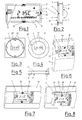
- FIGS. 1 and 2 in particular modular, Display, program input or switching and / or control device essentially from a display device 1, in particular from an LCD display that is movable, in particular about a central axis 2, and expediently mounted on all four sides 3, tiltable is.
- a suitable tiltable bearing 4 for the display device 1 a universal joint bearing is provided in the area of axis 2.
- electromechanical contact devices which, according to the Invention, by the manually directed function-conforming button-like Actuation of the display device 1 can be operated in accordance with the function are.
- electromechanical contact devices 5 instead of electromechanical contact devices 5, if necessary, contactless electronic sensors are also provided, by the directional tilting of the display device 1, are switchable or controllable like buttons.
- the display device 1 is expediently together with the contact devices 5 and / or corresponding electromechanical or electronic, not shown here, in particular working analog, Modular controllers, in a suitable board 6 or a corresponding housing, installed functionally, arranged and stored.
- the display device 1 is immobile is stored, and that front, above the display device 1 a crystal-clear mask 7 is provided, which is used for manual exposure, for manually directed actuation of the contact devices 5, in particular tiltable, arranged and mounted.
- FIG. 3 shows a circular display device 1, the for manually actuated actuation of the contact devices 5 or Similar control devices, in particular concentric to axis 2, cardan joint-like, is tiltable to the circumference 20, arranged and stored.
- the intended optoelectronic Display device can have a different cross section than that in 3 is a circular display device 1.
- the optoelectronic display on the front with a clear mask 7 is covered.
- the display can be arranged immovably under the mask 7.
- FIG. 6 shows a room thermostat clock in a surface-mounted housing 13. 1 describes the generous, relatively large area and thus clear trained, display device for program input and / or control according to the invention, corresponding to the functionally conforming arrow-shaped, operator-leading imprints 12, can be acted upon manually. This makes it possible there, provided accordingly, not more closely here shown, contact devices for temperature and / or time setting or time switch preselection.
- a room thermostat clock for flush mounting can be seen with a front housing panel 15 and a new one Display device 1 with spatially function-integrated program input and / or control device, the keyboard-like front 8, for Entry of switching and / or control data, in the respective arrow direction, according to the operator's imprints 12, manually relative is large and easy to operate.
- the modular display device 1 designed and arranged extractable from the housing panel 15.
- 18 denotes there provided on the upper side 17 of the device Buttons and / or setting controls, for presetting the room thermostat clock.
- the new, in particular modular constructed, display device 1 with integrated program input and / or control device not only advantageous in the devices mentioned above can be used, but also wherever relatively small spatial dimensions of the front or operating side of a device, for example with car radios, hi-fi devices and / or with stationary ones and / or mobile two-way radios, so-called cell phones, the largest possible Display display and largest possible, manually safe and convenient accessible keypads are required.
- the new device 1 is therefore advantageous in terms of space separate display and keyboard arrangements, without Limitation of display and program input, functionally full replaceable. It is sensible possible with the new device not just a certain function on a display select and / or program or set certain parameters, or to move a cursor, but with the new device is also an immediate and clear user interface on the front of the display ensured.
Description
Die Erfindung betrifft eine elektronische Anzeigevorrichtung mit einer
manuell bedienbaren Programmeingabe- und/oder Schaltvorrichtung für
Schalt- und/oder Regelgeräte, insbesondere für Raumthermostatuhren,
mit den Merkmalen nach dem Oberbegriff des Patentanspruchs 1.The invention relates to an electronic display device with a
manually operated program input and / or switching device for
Switching and / or control devices, in particular for room thermostat clocks,
with the features according to the preamble of
Bei einer derartigen, zum Zwecke der Programmierung und/oder zur Einstellung eines Reglers, manuell beaufschlagbaren Vorrichtung, ist es erforderlich, daß diese, auch bei relativ kleinen Geräte- oder Bedienungsseitenabmessungen, nicht nur relativ großflächig ausgebildet und damit leicht und übersichtlich bedienbar ist, sondern auch, daß diese zweckmäßig in eine Formgestaltung, insbesondere der Vorder- oder der Bedienungsseite derartiger Geräte, insbesondere von Zeitschaltuhren, Raumthermostatuhren, Raumtemperaturreglern, Heizungssteuerungen, oder dergl. Geräte, um nur einige Anwendungsmöglichkeiten zu nennen, integrierbar ist. Dabei soll sichergestellt sein, daß einerseits die, insbesondere optoelektronische, Anzeigevorrichtung, insbesondere ein LCD-Display, größtmöglich ausbildbar, und daß andererseits die Programmeingabe- und/oder Schaltvorrichtung technisch einfach aufgebaut, sowie wirtschaftlich herstellbar ist.In such a case, for the purpose of programming and / or for setting a regulator, a manually actuated device, it is required that these, even with relatively small device or operating side dimensions, not only trained and relatively large area so that it is easy and clear to use, but also that this Appropriately in a design, especially the front or the Operating side of such devices, in particular time switches, Room thermostats, room temperature controllers, heating controls, or Similar devices, to name just a few possible applications, can be integrated is. It should be ensured that on the one hand, in particular optoelectronic, display device, in particular an LCD display, as far as possible, and that on the other hand the program input and / or switching device is technically simple, and is economically producible.
Aus der W092/17831 ist eine elektronische Thermostatschaltuhr, mit einer optoelektronischen Anzeigevorrichtung und einer manuell bedienbaren, aus Einzeltasten gebildeten und auf der Gerätevorderseite angeordneten, Programmeingabevorrichtungen bekannt. Diese, in einem räumlich relativ kleinen Gerätegehäuse angeordnete, Anzeige- und dazu getrennt angeordnete Programmeingabevorrichtung ist mit dem erheblichen Nachteil behaftet, daß dort aufgrund der relativ kleinen Gerätegehäuseabmessungen, insbesondere der dadurch relativ kleinen Gerätevorderseite, sowohl die Anzeigevorrichtung, als auch die tastenförmige Programmeingabevorrichtung jeweils relativ klein ausgebildet sind, um insbesondere die erforderlichen Einzeltasten zueinander anzuordnen.From the W092 / 17831 is an electronic thermostat timer, with a optoelectronic display device and a manually operated, from Individual buttons formed and arranged on the front of the device, program input devices known. This, in a spatially relative small device housing arranged, display and separately arranged Program input device has the considerable disadvantage that that there because of the relatively small device housing dimensions, in particular the relatively small front of the device, both the display device, as well as the button-shaped program input device each are made relatively small, in particular the required Arrange individual keys to each other.
Nicht nur die Einzeltasten sind aufgrund der beengten räumlichen Abmessungen der Gerätevorderseite, mit einer äußerst kleinen Bedienungs- bzw. manuellen Beaufschlagungsfläche ausgebildet, sondern auch das optoelektronische Anzeigedisplay ist, bedingt durch die beengten räumlichen Verhältnisse, auf der Gerätevorderseite dort nur relativ klein ausbildbar angeordnet.Not only the single buttons are due to the cramped spatial dimensions the front of the device, with an extremely small operating or manual exposure surface, but also the optoelectronic Display display is, due to the limited space, can only be formed relatively small on the front of the device arranged.
Diese vorgenannten Nachteile umgeht zwar ein aus der EP-A-0332957 bekannt gewordenes Heizungssteuergerät, das auf der Gerätevorderseite bzw. einer Bedienungsplatte, mit einer relativ großflächigen optoelektronischen Anzeigevorrichtung ausgestattet ist, die im Umfangsbereich mit elektronischen Tastenfeldern versehen ist. D.h. die Anzeigevorrichtung ist als sogenannter Sensorbildschirm (touch screen) ausgebildet.These aforementioned disadvantages are avoided by a known from EP-A-0332957 heating control unit on the front of the unit or an operating panel with a relatively large-area optoelectronic Display device is equipped in the peripheral area is provided with electronic keypads. I.e. the display device is designed as a so-called touch screen.
Dieses Gerät besitzt zwar eine relativ großflächige Anzeigevorrichtung mit relativ großflächigen und übersichtlichen Tastenfeldern, die eine sichere manuelle Bedienung dieser Tasten gewährleisten. Der technische Aufwand dieses Sensorbildschirms ist jedoch verhältnismäßig groß und für den Einsatz in die eingangs erwähnten Geräte unwirtschaftlich.This device does have a relatively large display device with relatively large and clear keypads, the one ensure safe manual operation of these buttons. The technical However, the effort of this touchscreen is relatively large and uneconomical for use in the devices mentioned at the beginning.
Der Erfindung liegt die Aufgabe zugrunde, eine Anzeige-, Programmeingabe- und/oder Schaltvorrichtung für Geräte der eingangs genannten Art zu schaffen, bei der die Nachteile der bekannten Einrichtungen beseitigt sind und deren Anzeige- und Tastenfeld jeweils nicht nur größtmöglich ausgebildet, sondern auch optimal in ein Gerätedesign integrierbar und technisch rationell und wirtschaftlich herstellbar und den jeweiligen Geräteerfordernissen und dem -design optimal anpaßbar ist.The invention has for its object a display, program input and / or switching device for devices of the type mentioned create, in which the disadvantages of the known devices are eliminated and their display and keypad are not only the largest possible trained, but can also be optimally integrated into a device design and technically rational and economical to manufacture and the respective Device requirements and design can be optimally adapted.
Diese Aufgabe wird mit den Merkmalen im kennzeichnenden Teil des Patentanspruchs
1 gelöst, und in den Unteransprüchen sind weitere vorteilhafte
Einzelheiten beansprucht.This object is achieved with the features in the characterizing part of the
Vorteilhaft bei dieser neuen Anzeigevorrichtung mit integrierter Programmeingabe und/oder Schalt- bzw. Regelvorrichtung, insbesondere für den Einsatz in einer Raumthermostatuhr, ist nicht nur die elektro- oder elektronischmechanisch funktionell zweckmäßige Kombination einer optoelektronischen, insbesondere LCD-Anzeigevorrichtung, mit einer relativ großflächigen und übersichtlichen, manuell beaufschlagbaren Programmeingabe- und/oder Schalt- bzw. Regelvorrichtung, bei der die Anzeigevorrichtung, mindestens jedoch eine die Anzeige- oder Vorderseite der Anzeigevorrichtung abdeckende glasklare Maske, zur Betätigung mindestens einer, insbesondere im rückseitigen Bereich, insbesondere im Randbereich der Anzeigevorrichtung, vorgesehene elektrische und/oder elektronische Kontaktvorrichtung, um einen relativ kleinen Neigungswinkel, kippbar angeordnet und, zweckmäßigerweise kardanisch, gelagert ist, manuell gerichtet schlagbar, funktionsspezifisch zu betätigen, sondern auch, daß diese neue Vorrichtung, insbesondere als modulare Baueinheit aufgebaut, technisch relativ einfach, rationell und wirtschaftlich herstellbar ist.Advantageous with this new display device with integrated program input and / or switching or regulating device, in particular for use in a room thermostat clock is not just the electric or Functional combination of an optoelectronic, in particular LCD display device, with a relative large and clear, manually loadable program input and / or switching or regulating device in which the display device, however, at least one of the display or front of the display device covering, clear mask, for actuation at least one, especially in the back area, especially in the edge area the display device, provided electrical and / or electronic Contact device, tiltable by a relatively small angle of inclination and, conveniently gimbaled, manually directed beatable, function-specific to operate, but also that this new device, in particular constructed as a modular unit, is technically relatively simple, rational and economical to manufacture.
Insbesondere ist die neue Anzeigevorrichtung oder die die Anzeigevorrichtung vorderseitig abdeckende, Maske nach allen Seiten hin um einen bestimmten, relativ kleinen Winkel kippbar gelagertIn particular, the new display device or the display device mask covering on the front by one on all sides certain, relatively small angle tilted
Vorteilhaft ist ferner die optimale zweckmäßige Integrierbarkeit dieser neuen Anzeige-, Schalt- und/oder Regelvorrichtung, die jeden beliebigen vorderseitigen Querschnitt aufweisen kann, in Geräte der eingangs genannten Art. Zur funktionsspezifischen Bedienungsführung bei der Beaufschlagung der Anzzeigevorrichtung oder der Maske, sind dort zweckmäßigerweise auf der Vorderseite entsprechende Aufdrucke vorgesehen.It is also advantageous that it can be optimally integrated new display, switching and / or control device that any can have front cross-section, in devices of the aforementioned Art. For function-specific control when loading the display device or the mask are expedient there Appropriate prints are provided on the front.
Einige Ausführungs- und Anwendungsbeispiele der neuen Anzeige-, Programmeingabe- bzw. Schalt- und/oder Regelvorrichtung, sind in den Zeichnungen dargestellt und werden im folgenden näher erläutert. Es zeigen
- Fig. 1
- eine Vorderansicht auf eine rechteckige, seitlich jeweils kippbar gelagerte Vorrichtung,
- Fig. 2
- eine Seitenansicht auf die Vorrichtung nach Fig. 1,
- Fig. 3
- eine Vorderansicht auf eine kreisrunde, konzentrisch gelagerte, und allseitig kippbare Vorrichtung,
- Fig. 4
- eine Vorderansicht auf eine Vorrichtung mit einer verformbaren Vorderseite,
- Fig. 5
- eine Seitenansicht auf die Vorrichtung nach Fig. 4,
- Fig. 6
- eine perspektivische Ansicht auf eine Raumthermostatuhr in einer Aufputzausführung,
- Fig. 7
- eine perspektivische Ansicht auf eine Raumthermostatuhr in einer Unterputzausführung und
- Fig. 8
- eine perspektivische Ansicht der Raumthermostatuhr nach Fig. 7, mit herausgezogener Anzeige-, Programmeingabe- bzw. Schalt- und/ oder Regelvorrichtung.
- Fig. 1
- FIG. 2 shows a front view of a rectangular device that can be tilted laterally,
- Fig. 2
- 2 shows a side view of the device according to FIG. 1,
- Fig. 3
- a front view of a circular, concentrically mounted, and tiltable device,
- Fig. 4
- 2 shows a front view of a device with a deformable front,
- Fig. 5
- 3 shows a side view of the device according to FIG. 4,
- Fig. 6
- a perspective view of a room thermostat in a surface-mounted version,
- Fig. 7
- a perspective view of a room thermostat in a flush-mounted version and
- Fig. 8
- a perspective view of the room thermostat clock of FIG. 7, with the display, program input or switching and / or control device pulled out.
Die, in den Fig. 1 und 2 dargestellte, insbesondere modular aufgebaute,
Anzeige-, Programmeingabe- bzw. Schalt- und/oder Regelvorrichtung, besteht
im wesentlichen aus einer Anzeigevorrichtung 1, insbesondere aus
einem LCD-Display, das beweglich, insbesondere um eine zentrale Achse 2,
und zweckmäßigerweise jeweils nach allen vier Seiten 3 hin, kippbar gelagert
ist. Als zweckmäßiges kippbares Lager 4 für die Anzeigevorrichtung
1, ist eine Kardangelenklagerung im Bereich der Achse 2 vorgesehen.The, shown in FIGS. 1 and 2, in particular modular,
Display, program input or switching and / or control device
essentially from a
5 bezeichnet elektromechanische Kontaktvorrichtungen, die, gemäß der
Erfindung, durch die manuell gerichtete funktionskonforme tastenartige
Beaufschlagung der Anzeigevorrichtung 1 funktionskonform betätigbar
sind. Anstelle von elektromechanischen Kontaktvorrichtungen 5, sind
erforderlichenfalls auch kontaktlose elektronische Geber vorgesehen,
die durch die gerichtete, Kipp-Beaufschlagung der Anzeigevorrichtung 1,
tastenartig schalt- bzw. regelbar sind.5 denotes electromechanical contact devices which, according to the
Invention, by the manually directed function-conforming button-like
Actuation of the
Zweckmäßigerweise ist die Anzeigevorrichtung 1 zusammen mit den Kontaktvorrichtungen
5 und/oder entsprechenden elektromechanischen oder elektronischen,
hier nicht näher dargestellten, insbesondere analog arbeitenden,
Reglern modular aufgebaut, in einer zweckmäßigen Platine 6 oder
einem entsprechenden Gehäuse, funktionskonform installiert, angeordnet
und gelagert.The
Es liegt hier im Rahmen der Erfindung, daß die Anzeigevorrichtung 1 unbeweglich
gelagert ist, und daß vorderseitig, über der Anzeigevorrichtung
1 eine glasklare Maske 7 vorgesehen ist, die zur manuellen Beaufschlagung,
zur manuell gerichteten Betätigung der Kontaktvorrichtungen
5, insbesondere allseitig kippbar, angeordnet und gelagert ist.It is within the scope of the invention that the
12 bezeichnet bedienungsführende Aufdrucke auf der Vorderseite 8 der Anzeigevorrichtung
1 oder einer entsprechenden vorderseitigen glasklaren
Maske 7.12 denotes operator-leading imprints on the
Die Fig. 3 zeigt eine kreisrund ausgebildete Anzeigevorrichtung 1, die
zur manuell beaufschlagten Betätigung der Kontaktvorrichtungen 5 oder
dergl. Regelvorrichtungen, insbesondere konzentrisch zur Achse 2, kardangelenkartig,
zum Umfang 20 hin kippbar, angeordnet und gelagert ist.3 shows a
Es liegt im Rahmen der Erfindung, daß die vorgesehene optoelektronische
Anzeigevorrichtung einen anderen Querschnitt aufweisen kann, als die in
der Fig. 3 gezeigte kreisrunde Anzeigevorrichtung 1. In diesem Falle ist
es vorgesehen, daß das optoelektronische Display vorderseitig mit einer
glasklaren Maske 7 abgedeckt ist. Diese Maske 7, die Merkmale eines Gerätedesigns
aufweisen kann, ist den jeweiligen Programmeingabe- und/oder
Schalterfordernissen entsprechend, zur manuellen Beaufschlagung und zur
Betätiguung der vorgesehenen Kontaktvorrichtungen 5, kippbar angeordnet
und gelagert und auf der Vorderseite 8 mit entsprechenden bedienungsführenden
Aufdrucken 12 versehen. Das hier vorgesehene optoelektronische
Display kann unter der Maske 7 unbeweglich angeordnet sein.It is within the scope of the invention that the intended optoelectronic
Display device can have a different cross section than that in
3 is a
In Abänderung des allgemeinen Erfindungsgedankens ist es in diesem Rahmen
auch vorgesehen, daß, wie aus den Fig. 4 und 5 ersichtlich, die Vorderseite
8 einer Anzeigevorrichtung 1 ganz oder nur im Umfangsbereich 9,
insbesondere außerhalb der Anzeigevorrichtung 1, plastisch manuell verformbar
und formreversibel ausgebildet ist, zur manuellen mittelbaren
Betätigung der vorgesehenen Kontaktvorrichtungen 5 und/oder Regler.In a modification of the general idea of the invention, it is within this framework
also provided that, as can be seen from Figs. 4 and 5, the
Bei einer derartigen plastischen manuell verformbaren und formreversiblen
Ausführung, insbesondre einer Maske 7, für eine Anzeigevorrichtung
1, ist es möglich, raumspezifisch abgeteilte Tastenfelder 11 vorzusehen,
wie dies aus der Fig. 4 ersichtlich ist. 12 bezeichnet bedienungsführende
Aufdrucke auf der Vorderseite 8.With such a plastic, manually deformable and form-reversible
Execution, in particular a
Die Fig. 6 zeigt eine Raumthermostatuhr in einem Aufbaugehäuse 13. 1
bezeichnet die großzügig, relativ großflächig und damit übersichtlich
ausgebildete, Anzeigevorrichtung, die zur Programmeingabe und/oder Regelung
erfindungsgemäß, entsprechend den funktionskonform pfeilförmigen,
bedienungsführenden Aufdrucken 12, manuell gerichtet beaufschlagbar ist.
Damit ist es dort möglich, entsprechend vorgesehene, hier nicht näher
dargestellte, Kontaktvorrichtungen, zur Temperatur- und/oder zur Zeiteinstellung
bzw. Zeitschaltvorwahl, zu betätigen.6 shows a room thermostat clock in a surface-mounted
Es ist dort klar ersichtlich, daß durch den Einsatz der neuen Vorrichtung
1, mit einem räumlich relativ großen LCD-Display auf deren Vorderseite
8, relativ großflächige, manuell zweckmäßig beaufschlagbare Tastenfelder
geschaffen werden können.It can be clearly seen there that by using the
14 bezeichnet einen abnehmbaren oder abschwenkbar gelagerten Gehäusedeckel, hinter dem konventionelle Tasten und/oder Regler angeordnet sind, mittels derer eine sogenannte Voreinstellung der Raumthermostatuhr vorgenommen werden kann.14 denotes a removable or swivel-mounted housing cover, arranged behind the conventional buttons and / or controller are used to preset the room thermostat clock can be made.
Aus den Fig. 7 und 8 ist eine Raumthermostatuhr für Unterputzmontage
ersichtlich, mit einer vorderseitigen Gehäuseblende 15 und einer neuen
Anzeigevorrichtung 1, mit räumlich funktionsintegrierter Programmeingabe-
und/oder Regelvorrichtung, deren tastenfeldartige Vorderseite 8, zur
Eingabe von Schalt- und/oder Regeldaten, in der jeweiligen Pfeilrichtung,
entsprechend der bedienungsführenden Aufdrucke 12, manuell relativ
großflächig und bedienungsfreundlich beaufschlagbar ist.7 and 8 is a room thermostat clock for flush mounting
can be seen with a
Wie die Fig. 8 näher zeigt, ist die modular aufgebaute Anzeigevorrichtung
1, aus der Gehäuseblende 15 herausziehbar ausgebildet und angeordnet.
18 bezeichnet dort auf der Vorrichtungsoberseite 17 vorgesehene
Tasten und/oder Einstellregler, zur Voreinstellung der Raumthermostatuhr.As shown in FIG. 8 in more detail, is the
Es liegt im Rahmen der Erfindung, daß die neue, insbesondere modular
aufgebaute, Anzeigevorrichtung 1 mit integrierter Programmeingabe- und/
oder Regelvorrichtung, nicht nur in den eingangs erwähnten Geräten vorteilhaft
einsetzbar ist, sondern auch überall dort, wo bei relativ kleinen
räumlichen Abmessungen der Vorder- oder Bedienungsseite eines Gerätes,
beispielsweise bei Autoradios, HiFi-Geräten und/oder bei stationären
und/oder mobilen Funksprechgeräten, sogenannten Handy's, ein größtmögliches
Anzeigedisplay und größtmögliche, manuell sicher und bequem
bedienbare Tastenfelder erforderlich sind.It is within the scope of the invention that the new, in particular modular
constructed,
Mit der neuen Vorrichtung 1 sind demnach in vorteilhafter Weise räumlich
voneinander getrennt angeordnete Anzeige- und Tastaturanordnungen, ohne
Einschränkung der Anzeige und Programmeingabe, funktionstechnisch voll
ersetzbar. Dabei ist es mit der neuen Vorrichtung sinnvoll möglich,
nicht nur auf einer Anzeige bzw. einem Display eine bestimmte Funktion
anzuwählen und/oder bestimmte Parameter einzuprogrammieren bzw. einzustellen,
oder eine Cursor zu bewegen, sondern mit der neuen Vorrichtung
ist auch eine unmittelbare und klare Bedienungsführung auf der Anzeigevorderseite
sichergestellt.The
Claims (9)
- Electronic display device with a manually actuable program input and/or switching device, which is provided on the display device and which has the form of a keyboard, for switching and/or regulating apparatus, especially for room thermostat timers, characterised in that the display device (1), at least however a clear glass screen (7) covering the display side or front side (8) of the display device (1), is arranged and mounted to be tiltable for actuation of at least one electrical and/or electronic contact device (5).
- Device according to claim 1, characterised in that the contact device or devices (5) is or are arranged in the rear-sided region (19), especially in the edge region (19.1), of the display device (1), and is or are actuable specific to function by a manually directed loading of the display device (1) or the screen (7).
- Device according to claim 1 and 2, characterised in that the display device (1) or the screen (7) is constructed to be rectangular and that the display device (1) or the screen (7) is mounted, in particular, centrally and is tiltable to, in particular, each of the four sides (3).
- Device according to claim 1 and 2, characterised in that the display device (1) or the screen (7) is constructed to be circularly round and mounted to be tiltable concentrically with respect to the circumference (20).
- Device according to claim 1 to 4, characterised in that the display device (1) or the screen (7) is mounted to be tiltable by means of a Cardan joint (21).
- Device according to claim 1 to 5, characterised in that printings (12), which guide operation and which in particular are arrow-shaped, are provided on the front side (8) of the display device (1) or the screen (7).
- Device according to claim 1 to 6, characterised in that the display device (1), with or without a screen (7), together with at least one contact device (5) is constructed as a modular subassembly.
- Device according to claim 1 to 7, characterised in that the display device (1), with or without a screen (7), is incorporated in a surface-mounted housing (13), especially of a room thermostat timer, and that conventional buttons and/or regulators for a presetting of the room thermostat timer are additionally provided in the housing (13), in particular behind a housing cover (14) mounted at the front side to be removable or pivotable.
- Device according to claim 1 to 7, characterised in that the display device (1), with or without a screen (7), is incorporated in a housing hood (15) for an undersurface mounting, especially of a room thermostat timer, and that the modular display device (1) is mounted to be withdrawable from the housing hood (15) for operation of buttons (18) and/or setting regulators for the purpose of presetting the room thermostat timer.
Applications Claiming Priority (2)
| Application Number | Priority Date | Filing Date | Title |
|---|---|---|---|
| DE29607153U DE29607153U1 (en) | 1996-04-21 | 1996-04-21 | Electronic display device with a program input and / or switching device for switching and / or control devices, in particular for timers with a temperature control device |
| DE29607153U | 1996-04-21 |
Publications (3)
| Publication Number | Publication Date |
|---|---|
| EP0802471A2 EP0802471A2 (en) | 1997-10-22 |
| EP0802471A3 EP0802471A3 (en) | 1998-05-20 |
| EP0802471B1 true EP0802471B1 (en) | 1999-08-04 |
Family
ID=8022844
Family Applications (1)
| Application Number | Title | Priority Date | Filing Date |
|---|---|---|---|
| EP97104821A Expired - Lifetime EP0802471B1 (en) | 1996-04-21 | 1997-03-21 | Electronic displaying device provided with programmable input and control apparatus, particularly for room thermostat clocks |
Country Status (2)
| Country | Link |
|---|---|
| EP (1) | EP0802471B1 (en) |
| DE (2) | DE29607153U1 (en) |
Cited By (14)
| Publication number | Priority date | Publication date | Assignee | Title |
|---|---|---|---|---|
| US8843239B2 (en) | 2010-11-19 | 2014-09-23 | Nest Labs, Inc. | Methods, systems, and related architectures for managing network connected thermostats |
| US8918219B2 (en) | 2010-11-19 | 2014-12-23 | Google Inc. | User friendly interface for control unit |
| US8998102B2 (en) | 2011-10-21 | 2015-04-07 | Google Inc. | Round thermostat with flanged rotatable user input member and wall-facing optical sensor that senses rotation |
| US9026232B2 (en) | 2010-11-19 | 2015-05-05 | Google Inc. | Thermostat user interface |
| US9046414B2 (en) | 2012-09-21 | 2015-06-02 | Google Inc. | Selectable lens button for a hazard detector and method therefor |
| US9092039B2 (en) | 2010-11-19 | 2015-07-28 | Google Inc. | HVAC controller with user-friendly installation features with wire insertion detection |
| US9223323B2 (en) | 2010-09-14 | 2015-12-29 | Google Inc. | User friendly interface for control unit |
| US9298196B2 (en) | 2010-11-19 | 2016-03-29 | Google Inc. | Energy efficiency promoting schedule learning algorithms for intelligent thermostat |
| US9453655B2 (en) | 2011-10-07 | 2016-09-27 | Google Inc. | Methods and graphical user interfaces for reporting performance information for an HVAC system controlled by a self-programming network-connected thermostat |
| US9459018B2 (en) | 2010-11-19 | 2016-10-04 | Google Inc. | Systems and methods for energy-efficient control of an energy-consuming system |
| US9476606B2 (en) | 2010-12-31 | 2016-10-25 | Google Inc. | Dynamic device-associated feedback indicative of responsible device usage |
| US9552002B2 (en) | 2010-11-19 | 2017-01-24 | Google Inc. | Graphical user interface for setpoint creation and modification |
| US9607787B2 (en) | 2012-09-21 | 2017-03-28 | Google Inc. | Tactile feedback button for a hazard detector and fabrication method thereof |
| US10606724B2 (en) | 2010-11-19 | 2020-03-31 | Google Llc | Attributing causation for energy usage and setpoint changes with a network-connected thermostat |
Families Citing this family (13)
| Publication number | Priority date | Publication date | Assignee | Title |
|---|---|---|---|---|
| EP1731984A1 (en) * | 2005-05-31 | 2006-12-13 | Siemens Schweiz AG | Input and display device for process parameters |
| DE102007008625B4 (en) * | 2007-02-22 | 2010-03-18 | Abb Ag | Flush installation device for displaying information |
| US8727611B2 (en) | 2010-11-19 | 2014-05-20 | Nest Labs, Inc. | System and method for integrating sensors in thermostats |
| US9256230B2 (en) | 2010-11-19 | 2016-02-09 | Google Inc. | HVAC schedule establishment in an intelligent, network-connected thermostat |
| US11334034B2 (en) | 2010-11-19 | 2022-05-17 | Google Llc | Energy efficiency promoting schedule learning algorithms for intelligent thermostat |
| US10241527B2 (en) | 2010-11-19 | 2019-03-26 | Google Llc | Thermostat graphical user interface |
| US9075419B2 (en) | 2010-11-19 | 2015-07-07 | Google Inc. | Systems and methods for a graphical user interface of a controller for an energy-consuming system having spatially related discrete display elements |
| US8893032B2 (en) | 2012-03-29 | 2014-11-18 | Google Inc. | User interfaces for HVAC schedule display and modification on smartphone or other space-limited touchscreen device |
| US9222693B2 (en) | 2013-04-26 | 2015-12-29 | Google Inc. | Touchscreen device user interface for remote control of a thermostat |
| US9890970B2 (en) | 2012-03-29 | 2018-02-13 | Google Inc. | Processing and reporting usage information for an HVAC system controlled by a network-connected thermostat |
| US10054964B2 (en) | 2012-05-07 | 2018-08-21 | Google Llc | Building control unit method and controls |
| US8708242B2 (en) | 2012-09-21 | 2014-04-29 | Nest Labs, Inc. | Thermostat system with software-repurposable wiring terminals adaptable for HVAC systems of different ranges of complexity |
| DE102014104394B4 (en) | 2014-03-28 | 2016-09-08 | Berker Gmbh & Co. Kg | Wall-bound interface device |
Family Cites Families (2)
| Publication number | Priority date | Publication date | Assignee | Title |
|---|---|---|---|---|
| CH682264A5 (en) * | 1988-03-18 | 1993-08-13 | Tem Ag | |
| DE9104170U1 (en) * | 1991-04-06 | 1991-07-04 | Graesslin Kg, 7742 St Georgen, De |
-
1996
- 1996-04-21 DE DE29607153U patent/DE29607153U1/en not_active Expired - Lifetime
-
1997
- 1997-03-21 EP EP97104821A patent/EP0802471B1/en not_active Expired - Lifetime
- 1997-03-21 DE DE59700300T patent/DE59700300D1/en not_active Expired - Fee Related
Cited By (22)
| Publication number | Priority date | Publication date | Assignee | Title |
|---|---|---|---|---|
| US9223323B2 (en) | 2010-09-14 | 2015-12-29 | Google Inc. | User friendly interface for control unit |
| US9279595B2 (en) | 2010-09-14 | 2016-03-08 | Google Inc. | Methods, systems, and related architectures for managing network connected thermostats |
| US9552002B2 (en) | 2010-11-19 | 2017-01-24 | Google Inc. | Graphical user interface for setpoint creation and modification |
| US8843239B2 (en) | 2010-11-19 | 2014-09-23 | Nest Labs, Inc. | Methods, systems, and related architectures for managing network connected thermostats |
| US10606724B2 (en) | 2010-11-19 | 2020-03-31 | Google Llc | Attributing causation for energy usage and setpoint changes with a network-connected thermostat |
| US9092039B2 (en) | 2010-11-19 | 2015-07-28 | Google Inc. | HVAC controller with user-friendly installation features with wire insertion detection |
| US9127853B2 (en) | 2010-11-19 | 2015-09-08 | Google Inc. | Thermostat with ring-shaped control member |
| US9575496B2 (en) | 2010-11-19 | 2017-02-21 | Google Inc. | HVAC controller with user-friendly installation features with wire insertion detection |
| US9261289B2 (en) | 2010-11-19 | 2016-02-16 | Google Inc. | Adjusting proximity thresholds for activating a device user interface |
| US8918219B2 (en) | 2010-11-19 | 2014-12-23 | Google Inc. | User friendly interface for control unit |
| US9026232B2 (en) | 2010-11-19 | 2015-05-05 | Google Inc. | Thermostat user interface |
| US9298196B2 (en) | 2010-11-19 | 2016-03-29 | Google Inc. | Energy efficiency promoting schedule learning algorithms for intelligent thermostat |
| US9459018B2 (en) | 2010-11-19 | 2016-10-04 | Google Inc. | Systems and methods for energy-efficient control of an energy-consuming system |
| US9476606B2 (en) | 2010-12-31 | 2016-10-25 | Google Inc. | Dynamic device-associated feedback indicative of responsible device usage |
| US9732979B2 (en) | 2010-12-31 | 2017-08-15 | Google Inc. | HVAC control system encouraging energy efficient user behaviors in plural interactive contexts |
| US9453655B2 (en) | 2011-10-07 | 2016-09-27 | Google Inc. | Methods and graphical user interfaces for reporting performance information for an HVAC system controlled by a self-programming network-connected thermostat |
| US10295974B2 (en) | 2011-10-07 | 2019-05-21 | Google Llc | Methods and graphical user interfaces for reporting performance information for an HVAC system controlled by a self-programming network-connected thermostat |
| US9291359B2 (en) | 2011-10-21 | 2016-03-22 | Google Inc. | Thermostat user interface |
| US8998102B2 (en) | 2011-10-21 | 2015-04-07 | Google Inc. | Round thermostat with flanged rotatable user input member and wall-facing optical sensor that senses rotation |
| US9568370B2 (en) | 2012-09-21 | 2017-02-14 | Google Inc. | Selectable lens button for a smart home device and method therefor |
| US9607787B2 (en) | 2012-09-21 | 2017-03-28 | Google Inc. | Tactile feedback button for a hazard detector and fabrication method thereof |
| US9046414B2 (en) | 2012-09-21 | 2015-06-02 | Google Inc. | Selectable lens button for a hazard detector and method therefor |
Also Published As
| Publication number | Publication date |
|---|---|
| DE29607153U1 (en) | 1996-07-04 |
| EP0802471A3 (en) | 1998-05-20 |
| DE59700300D1 (en) | 1999-09-09 |
| EP0802471A2 (en) | 1997-10-22 |
Similar Documents
| Publication | Publication Date | Title |
|---|---|---|
| EP0802471B1 (en) | Electronic displaying device provided with programmable input and control apparatus, particularly for room thermostat clocks | |
| EP3554882B1 (en) | Operating device having an operating knob | |
| EP3352064B1 (en) | Light adjusting panel with touch sensors | |
| EP2008290B1 (en) | Dimmer | |
| DE69914792T2 (en) | PORTABLE TELEPHONE AND SWITCH-ON PROCESS | |
| EP3668743B1 (en) | Operating device for a motor vehicle | |
| DE19941956A1 (en) | Multi-function operating device for automobile has unit containing menu display and display function buttons which is separate from selection buttons | |
| DE60215882T2 (en) | Manual input device | |
| EP1907906A1 (en) | Method and control device for controlling one or several machines | |
| DE10037619A1 (en) | Arrangement of controls | |
| WO2012104070A2 (en) | Device for controlling multiple different functions of a motor vehicle | |
| DE102008041649A1 (en) | Screen-based vehicle operating system | |
| DE102009013440A1 (en) | Switching and/or releasing device for control panel in motor vehicle, has mechanical switching element designed such that switching element is operable by movement of touch-sensitive surface through pressing surface | |
| DE102005059735A1 (en) | Pointer indicating device for control panel of vehicle air conditioning system has operating unit which is of cylindrical form whereby clock shield, display area and pointer are arranged inside operating unit | |
| WO2008052889A1 (en) | Actuating element | |
| EP1076615A1 (en) | Control device | |
| EP2702472B1 (en) | User interface element for a lighting system | |
| DE602005002636T2 (en) | Exterior rearview mirror for motor vehicles with shape memory actuator | |
| DE19804399C2 (en) | Electrical household appliance with solar cell | |
| DE60300813T2 (en) | Device for selecting and confirming a function and dashboard provided therewith | |
| DE102009049111B4 (en) | Method for controlling the information display in a vehicle and operating device for a vehicle | |
| DE102006012472B3 (en) | Control unit for tanning device, has operating panel having functional display unit, coupled with control unit for adjustment of functions of tanning device by selection and adjustment of menu field by rotary switch | |
| DE2827075C2 (en) | Handset for operating electronically controllable devices | |
| EP1026041A2 (en) | Control unit, in particular multifunctional control unit | |
| DE102006055488A1 (en) | Adaptive operating device for use at surface in inner area of vehicle i.e. car, has interface transferring information to on-board system of vehicle, if operating unit is operated, where device is manufactured from flexible material |
Legal Events
| Date | Code | Title | Description |
|---|---|---|---|
| PUAI | Public reference made under article 153(3) epc to a published international application that has entered the european phase |
Free format text: ORIGINAL CODE: 0009012 |
|
| AK | Designated contracting states |
Kind code of ref document: A2 Designated state(s): DE FR IT NL |
|
| PUAL | Search report despatched |
Free format text: ORIGINAL CODE: 0009013 |
|
| AK | Designated contracting states |
Kind code of ref document: A3 Designated state(s): DE FR IT NL |
|
| 17P | Request for examination filed |
Effective date: 19980502 |
|
| GRAG | Despatch of communication of intention to grant |
Free format text: ORIGINAL CODE: EPIDOS AGRA |
|
| GRAG | Despatch of communication of intention to grant |
Free format text: ORIGINAL CODE: EPIDOS AGRA |
|
| GRAH | Despatch of communication of intention to grant a patent |
Free format text: ORIGINAL CODE: EPIDOS IGRA |
|
| GRAH | Despatch of communication of intention to grant a patent |
Free format text: ORIGINAL CODE: EPIDOS IGRA |
|
| 17Q | First examination report despatched |
Effective date: 19990209 |
|
| GRAA | (expected) grant |
Free format text: ORIGINAL CODE: 0009210 |
|
| AK | Designated contracting states |
Kind code of ref document: B1 Designated state(s): DE FR IT NL |
|
| REF | Corresponds to: |
Ref document number: 59700300 Country of ref document: DE Date of ref document: 19990909 |
|
| ITF | It: translation for a ep patent filed |
Owner name: DE DOMINICIS & MAYER S.R.L. |
|
| ET | Fr: translation filed | ||
| PLBE | No opposition filed within time limit |
Free format text: ORIGINAL CODE: 0009261 |
|
| STAA | Information on the status of an ep patent application or granted ep patent |
Free format text: STATUS: NO OPPOSITION FILED WITHIN TIME LIMIT |
|
| 26N | No opposition filed | ||
| PG25 | Lapsed in a contracting state [announced via postgrant information from national office to epo] |
Ref country code: FR Free format text: LAPSE BECAUSE OF NON-PAYMENT OF DUE FEES Effective date: 20010531 |
|
| REG | Reference to a national code |
Ref country code: FR Ref legal event code: ST |
|
| PGFP | Annual fee paid to national office [announced via postgrant information from national office to epo] |
Ref country code: NL Payment date: 20080324 Year of fee payment: 12 |
|
| PGFP | Annual fee paid to national office [announced via postgrant information from national office to epo] |
Ref country code: DE Payment date: 20080430 Year of fee payment: 12 |
|
| PG25 | Lapsed in a contracting state [announced via postgrant information from national office to epo] |
Ref country code: FR Free format text: LAPSE BECAUSE OF NON-PAYMENT OF DUE FEES Effective date: 20000331 |
|
| PGFP | Annual fee paid to national office [announced via postgrant information from national office to epo] |
Ref country code: IT Payment date: 20090324 Year of fee payment: 13 |
|
| NLV4 | Nl: lapsed or anulled due to non-payment of the annual fee |
Effective date: 20091001 |
|
| PG25 | Lapsed in a contracting state [announced via postgrant information from national office to epo] |
Ref country code: DE Free format text: LAPSE BECAUSE OF NON-PAYMENT OF DUE FEES Effective date: 20091001 |
|
| PG25 | Lapsed in a contracting state [announced via postgrant information from national office to epo] |
Ref country code: NL Free format text: LAPSE BECAUSE OF NON-PAYMENT OF DUE FEES Effective date: 20091001 |
|
| PG25 | Lapsed in a contracting state [announced via postgrant information from national office to epo] |
Ref country code: IT Free format text: LAPSE BECAUSE OF NON-PAYMENT OF DUE FEES Effective date: 20100321 |