EP0791848A2 - Display and method of operating a display - Google Patents
Display and method of operating a display Download PDFInfo
- Publication number
- EP0791848A2 EP0791848A2 EP97301054A EP97301054A EP0791848A2 EP 0791848 A2 EP0791848 A2 EP 0791848A2 EP 97301054 A EP97301054 A EP 97301054A EP 97301054 A EP97301054 A EP 97301054A EP 0791848 A2 EP0791848 A2 EP 0791848A2
- Authority
- EP
- European Patent Office
- Prior art keywords
- pixels
- sub
- display
- pixel
- liquid crystal
- Prior art date
- Legal status (The legal status is an assumption and is not a legal conclusion. Google has not performed a legal analysis and makes no representation as to the accuracy of the status listed.)
- Granted
Links
Images

Classifications
-
- G—PHYSICS
- G09—EDUCATION; CRYPTOGRAPHY; DISPLAY; ADVERTISING; SEALS
- G09G—ARRANGEMENTS OR CIRCUITS FOR CONTROL OF INDICATING DEVICES USING STATIC MEANS TO PRESENT VARIABLE INFORMATION
- G09G3/00—Control arrangements or circuits, of interest only in connection with visual indicators other than cathode-ray tubes
- G09G3/20—Control arrangements or circuits, of interest only in connection with visual indicators other than cathode-ray tubes for presentation of an assembly of a number of characters, e.g. a page, by composing the assembly by combination of individual elements arranged in a matrix no fixed position being assigned to or needed to be assigned to the individual characters or partial characters
- G09G3/34—Control arrangements or circuits, of interest only in connection with visual indicators other than cathode-ray tubes for presentation of an assembly of a number of characters, e.g. a page, by composing the assembly by combination of individual elements arranged in a matrix no fixed position being assigned to or needed to be assigned to the individual characters or partial characters by control of light from an independent source
- G09G3/36—Control arrangements or circuits, of interest only in connection with visual indicators other than cathode-ray tubes for presentation of an assembly of a number of characters, e.g. a page, by composing the assembly by combination of individual elements arranged in a matrix no fixed position being assigned to or needed to be assigned to the individual characters or partial characters by control of light from an independent source using liquid crystals
- G09G3/3611—Control of matrices with row and column drivers
- G09G3/3622—Control of matrices with row and column drivers using a passive matrix
- G09G3/3629—Control of matrices with row and column drivers using a passive matrix using liquid crystals having memory effects, e.g. ferroelectric liquid crystals
-
- G—PHYSICS
- G02—OPTICS
- G02F—OPTICAL DEVICES OR ARRANGEMENTS FOR THE CONTROL OF LIGHT BY MODIFICATION OF THE OPTICAL PROPERTIES OF THE MEDIA OF THE ELEMENTS INVOLVED THEREIN; NON-LINEAR OPTICS; FREQUENCY-CHANGING OF LIGHT; OPTICAL LOGIC ELEMENTS; OPTICAL ANALOGUE/DIGITAL CONVERTERS
- G02F1/00—Devices or arrangements for the control of the intensity, colour, phase, polarisation or direction of light arriving from an independent light source, e.g. switching, gating or modulating; Non-linear optics
- G02F1/01—Devices or arrangements for the control of the intensity, colour, phase, polarisation or direction of light arriving from an independent light source, e.g. switching, gating or modulating; Non-linear optics for the control of the intensity, phase, polarisation or colour
- G02F1/13—Devices or arrangements for the control of the intensity, colour, phase, polarisation or direction of light arriving from an independent light source, e.g. switching, gating or modulating; Non-linear optics for the control of the intensity, phase, polarisation or colour based on liquid crystals, e.g. single liquid crystal display cells
- G02F1/133—Constructional arrangements; Operation of liquid crystal cells; Circuit arrangements
- G02F1/1333—Constructional arrangements; Manufacturing methods
- G02F1/1335—Structural association of cells with optical devices, e.g. polarisers or reflectors
- G02F1/133528—Polarisers
- G02F1/133531—Polarisers characterised by the arrangement of polariser or analyser axes
-
- G—PHYSICS
- G02—OPTICS
- G02F—OPTICAL DEVICES OR ARRANGEMENTS FOR THE CONTROL OF LIGHT BY MODIFICATION OF THE OPTICAL PROPERTIES OF THE MEDIA OF THE ELEMENTS INVOLVED THEREIN; NON-LINEAR OPTICS; FREQUENCY-CHANGING OF LIGHT; OPTICAL LOGIC ELEMENTS; OPTICAL ANALOGUE/DIGITAL CONVERTERS
- G02F1/00—Devices or arrangements for the control of the intensity, colour, phase, polarisation or direction of light arriving from an independent light source, e.g. switching, gating or modulating; Non-linear optics
- G02F1/01—Devices or arrangements for the control of the intensity, colour, phase, polarisation or direction of light arriving from an independent light source, e.g. switching, gating or modulating; Non-linear optics for the control of the intensity, phase, polarisation or colour
- G02F1/13—Devices or arrangements for the control of the intensity, colour, phase, polarisation or direction of light arriving from an independent light source, e.g. switching, gating or modulating; Non-linear optics for the control of the intensity, phase, polarisation or colour based on liquid crystals, e.g. single liquid crystal display cells
- G02F1/133—Constructional arrangements; Operation of liquid crystal cells; Circuit arrangements
- G02F1/1333—Constructional arrangements; Manufacturing methods
- G02F1/1343—Electrodes
- G02F1/134309—Electrodes characterised by their geometrical arrangement
- G02F1/134345—Subdivided pixels, e.g. for grey scale or redundancy
-
- G—PHYSICS
- G09—EDUCATION; CRYPTOGRAPHY; DISPLAY; ADVERTISING; SEALS
- G09G—ARRANGEMENTS OR CIRCUITS FOR CONTROL OF INDICATING DEVICES USING STATIC MEANS TO PRESENT VARIABLE INFORMATION
- G09G2310/00—Command of the display device
- G09G2310/06—Details of flat display driving waveforms
-
- G—PHYSICS
- G09—EDUCATION; CRYPTOGRAPHY; DISPLAY; ADVERTISING; SEALS
- G09G—ARRANGEMENTS OR CIRCUITS FOR CONTROL OF INDICATING DEVICES USING STATIC MEANS TO PRESENT VARIABLE INFORMATION
- G09G2310/00—Command of the display device
- G09G2310/06—Details of flat display driving waveforms
- G09G2310/061—Details of flat display driving waveforms for resetting or blanking
-
- G—PHYSICS
- G09—EDUCATION; CRYPTOGRAPHY; DISPLAY; ADVERTISING; SEALS
- G09G—ARRANGEMENTS OR CIRCUITS FOR CONTROL OF INDICATING DEVICES USING STATIC MEANS TO PRESENT VARIABLE INFORMATION
- G09G2320/00—Control of display operating conditions
- G09G2320/04—Maintaining the quality of display appearance
- G09G2320/041—Temperature compensation
-
- G—PHYSICS
- G09—EDUCATION; CRYPTOGRAPHY; DISPLAY; ADVERTISING; SEALS
- G09G—ARRANGEMENTS OR CIRCUITS FOR CONTROL OF INDICATING DEVICES USING STATIC MEANS TO PRESENT VARIABLE INFORMATION
- G09G3/00—Control arrangements or circuits, of interest only in connection with visual indicators other than cathode-ray tubes
- G09G3/20—Control arrangements or circuits, of interest only in connection with visual indicators other than cathode-ray tubes for presentation of an assembly of a number of characters, e.g. a page, by composing the assembly by combination of individual elements arranged in a matrix no fixed position being assigned to or needed to be assigned to the individual characters or partial characters
- G09G3/2007—Display of intermediate tones
Definitions
- the present invention relates to a display, such as a liquid crystal display (LCD).
- a display such as a liquid crystal display (LCD).
- LCD liquid crystal display
- a known type of LCD panel comprises a matrix of picture elements (pixels), each of which is located at the intersection of a strobe electrode and a data electrode.
- Displays of this type may use a ferroelectric liquid crystal (FLC) and, by applying suitable data and strobe signals, it is possible to display one or more grey levels having light transmissivity or reflectivity between minimum and maximum values which are referred to as black and white levels.
- FLC ferroelectric liquid crystal
- This technique for achieving grey levels (by analogue means) may be used alone or in combination with spatial and/or temporal techniques for providing grey levels. It is thus possible to provide a large number of grey levels so as to increase the utility and range of applications of panel displays of this type.
- a difficulty of achieving grey levels with displays of this type is that the grey levels are sensitive to variations in temperature, panel thickness i.e. thickness of the liquid crystal layer, and pixel pattern i.e. variations in switching sensitivity of each pixel as a result of data signals applied to other pixels.
- temperature variations cause the grey levels to vary from the levels expected of the data signals.
- grey levels are so sensitive to temperature variation that small temperature variations over the display area can have a substantial effect on grey levels.
- relatively small thickness variations in the liquid crystal layer over a small scale within the panel for instance resulting from manufacturing tolerances, can have a substantial effect on grey levels. Such effects therefore limit the number of grey levels which can be reliably addressed and can have a detrimental effect on the quality of images displayed by the display.
- JP-A-5-27719 discloses a ferroelectric liquid crystal display of the pixellated type. Each pixel is physically divided into two sub-pixels whose optical properties are individually controllable. In order to switch a pixel to a desired grey level, one of the sub-pixels is blanked to white and then switched from the white state so as to try to achieve the desired grey level. The other sub-pixel is blanked to black and then similarly switched so as to try to achieved the desired grey level.
- the effects of temperature variations and differences in thickness of the ferroelectric liquid crystal result in shifts of the function relating optical transmissivity to switching waveform.
- Both sub-pixels are affected in the same way but, because the sub-pixels are initially blanked to opposite states before being switched towards the desired grey level, the effects of such variations at least partially cancel out and the perceived grey level of the whole pixel is made substantially less dependent on variations, for instance in temperature or ferroelectric liquid crystal thickness.
- an effect which tends to make the grey level achieved by one sub-pixel darker than expected tends to make the other sub-pixel lighter than expected.
- JP-A-27719 is capable of compensating for temperature variations and variations in liquid crystal thickness for bistable liquid crystals such as ferroelectric liquid crystals.
- this arrangement is unsuitable for non-bistable liquid crystals, which suffer from similar problems of sensitivity to temperature and liquid crystal thickness.
- a liquid crystal display comprising a plurality of pixels, each of which is spatially divided to form a first sub-pixel and a second sub-pixel, and a control arrangement for selectively switching each pixel to an intermediate optical state between a maximum attenuation optical state and a minimum attenuation optical state by switching the first and second sub-pixels to the intermediate optical state, characterised in that each of the first sub-pixels has input and output linear polarisers whose polarisation directions are parallel and each of the second sub-pixels has input and output linear polarisers whose polarising directions are orthogonal.
- this technique may be applied to displays operating in RMS responding nematic modes such as twisted nematic and supertwisted nematic liquid crystals.
- the display comprises a spatially uniformly polarising layer forming one of the input and output polarisers of the first and second sub-pixels.
- the use of only one patterned polariser avoids the cost of a second patterned polariser and avoids any manufacturing difficulty which might be associated with registration of two patterned polarisers.
- the display comprises a spatially non-uniformly polarising layer having alternating elongate first and second regions forming the other of the input and output polarisers, the first and second regions being aligned with the first and second sub-pixels, respectively.
- This provides a particularly simple patterned polariser which is thus easier to manufacture.
- first and second regions of each adjacent pair are aligned with first and second sub-electrodes of a respective addressing electrode.
- each of the pixels comprises first and second display regions forming the first and second sub-pixels, respectively.
- the first and second sub-pixels are independently addressable.
- the control arrangement may be arranged to refresh the first and second sub-pixels of each pixel simultaneously.
- the control arrangement may be arranged to refresh the first and second sub-pixels of each pixel sequentially.
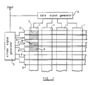
- Figure 1 shows part of an LCD comprising a matrix of pixels formed at the intersections of data or column electrodes 1 and strobe or row electrodes 2 and 3.
- the data electrodes 1 are connected to a data signal generator 4 and the strobe electrodes 2 and 3 are connected to a strobe signal generator 5.
- the data and strobe signal generators 4 and 5 are connected to a display input 6 which supplies image data to the data signal generator 4 and clock signals to the generators 4 and 5.
- the strobe electrodes for each row of pixels are divided into two electrodes 2 and 3.
- Each pixel such as that indicated by shading at 7, is defined by the intersection of one of the data electrodes 1 and an adjacent pair of the strobe electrodes 2 and 3.
- the pixels are divided into first and second sub-pixels, such as those indicated by different directions of shading at 8 and 9, by the intersections of the data electrodes and the split strobe electrodes 2 and 3, respectively.
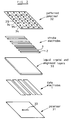
- the display further comprises a layer of twisted nematic or super twisted nematic liquid crystal material disposed between appropriate alignment layers as indicated at 30 in Figure 2.
- a plane polariser 31 having a polarisation direction indicated by the arrow 33 is disposed on one side of the liquid crystal and alignment layers 30 whereas a patterned polariser 32 is disposed on the other side.
- the patterned polariser 32 comprises strips 34 and 35 which are aligned with the strobe electrodes 2 and 3, respectively.
- the polarisation direction of the strips 34 is parallel to the polarisation direction 33 of the polariser 31 whereas the polarisation direction of the strips 35 is perpendicular thereto.
- the patterned polariser 32 may be made using polymerisable films, for instance as disclosed in US 5 235 449. A molecular film is coated onto a surface and polymerised in a predetermined pattern. The unpolymerised material is then removed to leave regions with polarisations in different directions.
- the patterned polariser 32 may comprise a continuous polariser and a patterned polarisation rotator. Such an arrangement is disclosed in GB 2 296 099 and EP 0 721 132.
- the pixels of the display are thus spatially divided into sub-pixels with the sub-pixels 8 aligned with the strips 34 operating in the normally black mode whereas the sub-pixels 9 aligned with the strips 35 operate in the normally white mode.
- FIG 3 illustrates the waveforms which are applied to the electrodes 1, 2 and 3 so as to address the individual sub-pixels. Bipolar waveforms are shown but monopolar pulses may also be used.
- the sub-pixels operating in the normally white mode are switched towards the black state whereas the pixels operating in the normally black mode are switched towards the white state.
- the liquid crystal responds to the average voltage thereacross for a frame.
- different grey levels may be achieved by applying data signals of different amplitudes Vd.
- the transmission curves of the normally white and normally black sub-pixels shift in opposite directions for a particular direction of change in temperature.
- the grey levels produced by the sub-pixels are integrated by the eye of the observer who therefore perceives the average grey level for each pixel so that variations in grey level are substantially reduced.
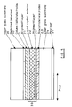
- the cross-sectional view of Figure 5 illustrates the positions of the various components of the display.
- the patterned polariser 32 and the data electrodes 1 are disposed between an upper glass substrate 20 and an alignment layer 21.
- the strobe electrodes 2, 3 are disposed between an alignment layer 23 and a lower glass substrate 24.
- the liquid crystal material 22 is disposed between the alignment layers 21 and 23.
- the patterned polariser 32 may alternatively be disposed between the data electrodes 1 and the alignment layer 22 but such an arrangement is not preferred because the polariser 32 would affect the field applied across the liquid crystal material 22.
- the patterned polariser 32 is disposed between the substrates 20 and 24 so that parallax effects can be substantially reduced.
- the strobe waveforms may be supplied sequentially to the strobe electrodes 2 and 3 of each row of pixels.
- the strobe signals may be supplied simultaneously to the electrodes 2 and 3 of each pixel row so that both sub-pixels 8 and 9 of each pixel 7 are switched simultaneously.
- simultaneous strobing is possible when the data waveforms are such that the black and white switching waveforms switch one of the sub-pixels but not the other.
- Simultaneous strobing doubles the refresh rate of the display and may reduce the effects of pixel pattern.
- This technique may be used to compensate for variations which are caused by other effects and which shift the transmission curves of the sub-pixels 8 and 9 in opposite directions.
- variations in grey level caused by and variations in cell thickness can be substantially reduced.
- the sub-pixels 8 and 9 have the same display areas.
- the relative display areas of the sub-pixels may be varied so as to compensate for differences in the switching curves.
- This technique may be applied to other non-bistable display types including birefringence mode displays using nematic liquid crystals and modes with different twists such as pi-cells, optical interference displays and distorted helix ferroelectric liquid crystals.
- passive matrix addressing has been described, this technique is also applicable to active matrix addressing. In this case, the sub-pixels may be divided in the columns rather than in the rows.
Abstract

Description
- The present invention relates to a display, such as a liquid crystal display (LCD).
- A known type of LCD panel comprises a matrix of picture elements (pixels), each of which is located at the intersection of a strobe electrode and a data electrode. Displays of this type may use a ferroelectric liquid crystal (FLC) and, by applying suitable data and strobe signals, it is possible to display one or more grey levels having light transmissivity or reflectivity between minimum and maximum values which are referred to as black and white levels. This technique for achieving grey levels (by analogue means) may be used alone or in combination with spatial and/or temporal techniques for providing grey levels. It is thus possible to provide a large number of grey levels so as to increase the utility and range of applications of panel displays of this type.
- A difficulty of achieving grey levels with displays of this type is that the grey levels are sensitive to variations in temperature, panel thickness i.e. thickness of the liquid crystal layer, and pixel pattern i.e. variations in switching sensitivity of each pixel as a result of data signals applied to other pixels. In the absence of compensation, temperature variations cause the grey levels to vary from the levels expected of the data signals. Although techniques are known for compensating for large scale changes in temperature affecting the whole of a display panel, grey levels are so sensitive to temperature variation that small temperature variations over the display area can have a substantial effect on grey levels. Similarly, relatively small thickness variations in the liquid crystal layer over a small scale within the panel, for instance resulting from manufacturing tolerances, can have a substantial effect on grey levels. Such effects therefore limit the number of grey levels which can be reliably addressed and can have a detrimental effect on the quality of images displayed by the display.
- JP-A-5-27719 discloses a ferroelectric liquid crystal display of the pixellated type. Each pixel is physically divided into two sub-pixels whose optical properties are individually controllable. In order to switch a pixel to a desired grey level, one of the sub-pixels is blanked to white and then switched from the white state so as to try to achieve the desired grey level. The other sub-pixel is blanked to black and then similarly switched so as to try to achieved the desired grey level. However, the effects of temperature variations and differences in thickness of the ferroelectric liquid crystal result in shifts of the function relating optical transmissivity to switching waveform. Both sub-pixels are affected in the same way but, because the sub-pixels are initially blanked to opposite states before being switched towards the desired grey level, the effects of such variations at least partially cancel out and the perceived grey level of the whole pixel is made substantially less dependent on variations, for instance in temperature or ferroelectric liquid crystal thickness. In particular, an effect which tends to make the grey level achieved by one sub-pixel darker than expected tends to make the other sub-pixel lighter than expected.
- The arrangement disclosed in JP-A-27719 is capable of compensating for temperature variations and variations in liquid crystal thickness for bistable liquid crystals such as ferroelectric liquid crystals. However, this arrangement is unsuitable for non-bistable liquid crystals, which suffer from similar problems of sensitivity to temperature and liquid crystal thickness.
- According to the invention, there is provided a liquid crystal display comprising a plurality of pixels, each of which is spatially divided to form a first sub-pixel and a second sub-pixel, and a control arrangement for selectively switching each pixel to an intermediate optical state between a maximum attenuation optical state and a minimum attenuation optical state by switching the first and second sub-pixels to the intermediate optical state, characterised in that each of the first sub-pixels has input and output linear polarisers whose polarisation directions are parallel and each of the second sub-pixels has input and output linear polarisers whose polarising directions are orthogonal.
- It is thus possible to use a spatial averaging technique to eliminate or reduce grey level variations caused by temperature variations and liquid crystal thickness variations with non-bistable liquid crystals. For instance, this technique may be applied to displays operating in RMS responding nematic modes such as twisted nematic and supertwisted nematic liquid crystals.
- Preferably the display comprises a spatially uniformly polarising layer forming one of the input and output polarisers of the first and second sub-pixels. The use of only one patterned polariser avoids the cost of a second patterned polariser and avoids any manufacturing difficulty which might be associated with registration of two patterned polarisers.
- Preferably the display comprises a spatially non-uniformly polarising layer having alternating elongate first and second regions forming the other of the input and output polarisers, the first and second regions being aligned with the first and second sub-pixels, respectively. This provides a particularly simple patterned polariser which is thus easier to manufacture.
- Preferably the first and second regions of each adjacent pair are aligned with first and second sub-electrodes of a respective addressing electrode.
- Preferably each of the pixels comprises first and second display regions forming the first and second sub-pixels, respectively.
- Preferably the first and second sub-pixels are independently addressable. The control arrangement may be arranged to refresh the first and second sub-pixels of each pixel simultaneously. Alternatively, the control arrangement may be arranged to refresh the first and second sub-pixels of each pixel sequentially.
- The invention will be further described by way of example, with reference to the accompanying drawings, in which:
- Figure 1 is a schematic diagram of a liquid crystal display constituting an embodiment of the invention;
- Figure 2 is a schematic exploded diagram of the display of Figure 1;
- Figure 3 illustrates strobe and data waveforms which may be used in the display of Figures 1 and 2;
- Figure 4 shows graphs of light transmission against data waveforms for first and second sub-pixels of the display of Figures 1 and 2 illustrating the effects of temperature variation; and
- Figure 5 is a cross-sectional view of the display of Figure 1.
- Figure 1 shows part of an LCD comprising a matrix of pixels formed at the intersections of data or
column electrodes 1 and strobe orrow electrodes data electrodes 1 are connected to a data signal generator 4 and thestrobe electrodes - Compared with known matrix-type LCDs the strobe electrodes for each row of pixels are divided into two
electrodes data electrodes 1 and an adjacent pair of thestrobe electrodes split strobe electrodes - The display further comprises a layer of twisted nematic or super twisted nematic liquid crystal material disposed between appropriate alignment layers as indicated at 30 in Figure 2. A
plane polariser 31 having a polarisation direction indicated by thearrow 33 is disposed on one side of the liquid crystal andalignment layers 30 whereas a patternedpolariser 32 is disposed on the other side. The patternedpolariser 32 comprisesstrips strobe electrodes strips 34 is parallel to thepolarisation direction 33 of thepolariser 31 whereas the polarisation direction of thestrips 35 is perpendicular thereto. - The patterned
polariser 32 may be made using polymerisable films, for instance as disclosed in US 5 235 449. A molecular film is coated onto a surface and polymerised in a predetermined pattern. The unpolymerised material is then removed to leave regions with polarisations in different directions. - Alternatively, the patterned
polariser 32 may comprise a continuous polariser and a patterned polarisation rotator. Such an arrangement is disclosed inGB 2 296 099 and EP 0 721 132. - The pixels of the display are thus spatially divided into sub-pixels with the sub-pixels 8 aligned with the
strips 34 operating in the normally black mode whereas thesub-pixels 9 aligned with thestrips 35 operate in the normally white mode. - Figure 3 illustrates the waveforms which are applied to the
electrodes - The cross-sectional view of Figure 5 illustrates the positions of the various components of the display. The patterned
polariser 32 and thedata electrodes 1 are disposed between anupper glass substrate 20 and analignment layer 21. Thestrobe electrodes alignment layer 23 and a lower glass substrate 24. Theliquid crystal material 22 is disposed between thealignment layers polariser 32 may alternatively be disposed between thedata electrodes 1 and thealignment layer 22 but such an arrangement is not preferred because thepolariser 32 would affect the field applied across theliquid crystal material 22. The patternedpolariser 32 is disposed between thesubstrates 20 and 24 so that parallax effects can be substantially reduced. - The strobe waveforms may be supplied sequentially to the
strobe electrodes electrodes sub-pixels 8 and 9 of eachpixel 7 are switched simultaneously. Such simultaneous strobing is possible when the data waveforms are such that the black and white switching waveforms switch one of the sub-pixels but not the other. Simultaneous strobing doubles the refresh rate of the display and may reduce the effects of pixel pattern. - Other known techniques are used for compensating for large scale temperature variations of the whole display panel. By using the technique described hereinbefore to compensate for changes in grey level with temperature, small scale temperature variations across the display panel can be compensated so as to reduce the variation in grey level.
- This technique may be used to compensate for variations which are caused by other effects and which shift the transmission curves of the sub-pixels 8 and 9 in opposite directions. Thus, variations in grey level caused by and variations in cell thickness can be substantially reduced.
- In the display described hereinbefore, it has been assumed that the sub-pixels 8 and 9 have the same display areas. However, the relative display areas of the sub-pixels may be varied so as to compensate for differences in the switching curves.
- This technique may be applied to other non-bistable display types including birefringence mode displays using nematic liquid crystals and modes with different twists such as pi-cells, optical interference displays and distorted helix ferroelectric liquid crystals. Also, although passive matrix addressing has been described, this technique is also applicable to active matrix addressing. In this case, the sub-pixels may be divided in the columns rather than in the rows.
Claims (9)
- A liquid crystal display comprising a plurality of pixels (7), each of which is spatially divided to form a first sub-pixel (8) and a second sub-pixel (9), and a control arrangement (4, 5) for selectively switching each pixel (7) to an intermediate optical state between a maximum attenuation optical state and a minimum attenuation optical state by switching the first and second sub-pixels (8, 9) to the intermediate optical state, characterised in that each of the first sub-pixels (8) has input and output linear polarisers (31, 34) whose polarisation directions are parallel and each of the second sub-pixels (9) has input and output linear polarisers (31, 35) whose polarising directions are orthogonal.
- A display as claimed in Claim 1, characterised by a spatially uniformly polarising layer (31) forming one of the input and output polarisers of the first and second sub-pixels (8, 9).
- A display as claimed in Claim 2, characterised by spatially non-uniformly polarising layer (32) having alternating elongate first and second regions (34, 35) forming the other of the input and output polarisers, the first and second regions (34, 35) being aligned with the first and sub-pixels, respectively.
- A display as claimed in Claim 3, characterised in that the first and second regions (34, 35) of each adjacent pair are aligned with first and second sub-electrodes (2, 3) of a respective addressing electrode.
- A display as claimed in any one of the preceding claims, characterised in that each of the pixels (7) comprises first and second display regions forming the first and second sub-pixels (8, 9), respectively.
- A display as claimed in any one of the preceding claims, characterised in that the first and second sub-pixels (8, 9) are independently addressable.
- A display as claimed in Claim 6, Characterised in that the control arrangement (4, 5) is arranged to refresh the first and second sub-pixels (8, 9) of each pixel (7) simultaneously.
- A display as claimed in Claim 6, characterised in that the control arrangement (4, 5) is arranged to refresh the first and second sub-pixels (8, 9) of each pixel (7) sequentially.
- A display as claimed in any one of the preceding claims, characterised in that the pixels (7) contain twisted nematic or supertwisted nematic liquid crystal.
Applications Claiming Priority (2)
| Application Number | Priority Date | Filing Date | Title |
|---|---|---|---|
| GB9603506A GB2310524A (en) | 1996-02-20 | 1996-02-20 | Display exhibiting grey levels |
| GB9603506 | 1996-02-20 |
Publications (3)
| Publication Number | Publication Date |
|---|---|
| EP0791848A2 true EP0791848A2 (en) | 1997-08-27 |
| EP0791848A3 EP0791848A3 (en) | 1998-10-28 |
| EP0791848B1 EP0791848B1 (en) | 2001-12-12 |
Family
ID=10789046
Family Applications (2)
| Application Number | Title | Priority Date | Filing Date |
|---|---|---|---|
| EP97301053A Withdrawn EP0791912A3 (en) | 1996-02-20 | 1997-02-19 | Display with two pixel optical states and method of operating the same with compensation of grey level variations |
| EP97301054A Expired - Lifetime EP0791848B1 (en) | 1996-02-20 | 1997-02-19 | Display and method of operating a display |
Family Applications Before (1)
| Application Number | Title | Priority Date | Filing Date |
|---|---|---|---|
| EP97301053A Withdrawn EP0791912A3 (en) | 1996-02-20 | 1997-02-19 | Display with two pixel optical states and method of operating the same with compensation of grey level variations |
Country Status (5)
| Country | Link |
|---|---|
| US (2) | US6061043A (en) |
| EP (2) | EP0791912A3 (en) |
| JP (2) | JPH09236798A (en) |
| DE (1) | DE69708949T2 (en) |
| GB (1) | GB2310524A (en) |
Cited By (1)
| Publication number | Priority date | Publication date | Assignee | Title |
|---|---|---|---|---|
| US6842297B2 (en) | 2001-08-31 | 2005-01-11 | Cdm Optics, Inc. | Wavefront coding optics |
Families Citing this family (31)
| Publication number | Priority date | Publication date | Assignee | Title |
|---|---|---|---|---|
| GB2325555A (en) * | 1997-05-20 | 1998-11-25 | Sharp Kk | Light modulating devices |
| TW428158B (en) * | 1998-02-24 | 2001-04-01 | Nippon Electric Co | Method and device for driving liquid crystal display element |
| US7292214B2 (en) * | 1999-01-11 | 2007-11-06 | Microdisplay Corporation | Method and apparatus for enhanced performance liquid crystal displays |
| GB2347547B (en) * | 1999-03-02 | 2003-02-12 | Sharp Kk | Addressing scheme for liquid crystal displays |
| KR100344186B1 (en) * | 1999-08-05 | 2002-07-19 | 주식회사 네오텍리서치 | source driving circuit for driving liquid crystal display and driving method is used for the circuit |
| JP2002333870A (en) * | 2000-10-31 | 2002-11-22 | Matsushita Electric Ind Co Ltd | Liquid crystal display device, el display device and drive method therefor and display pattern evaluation method of subpixel |
| WO2002067238A2 (en) * | 2001-02-16 | 2002-08-29 | Koninklijke Philips Electronics N.V. | Display device |
| TW548487B (en) * | 2001-05-07 | 2003-08-21 | Vrex Inc | Single cell liquid crystal shutter glasses |
| GB2379549A (en) * | 2001-09-06 | 2003-03-12 | Sharp Kk | Active matrix display |
| KR100924747B1 (en) * | 2002-09-23 | 2009-11-05 | 엘지디스플레이 주식회사 | Wide viewing angle LCD |
| KR101066483B1 (en) * | 2004-06-30 | 2011-09-22 | 엘지디스플레이 주식회사 | Liquid Crystal Display Device and Method for Manufacturing the Same |
| JP4622652B2 (en) * | 2005-04-22 | 2011-02-02 | エプソンイメージングデバイス株式会社 | Electro-optical device, driving method, and electronic apparatus |
| US8243013B1 (en) | 2007-05-03 | 2012-08-14 | Sipix Imaging, Inc. | Driving bistable displays |
| CN101308297B (en) * | 2007-05-14 | 2012-03-21 | 奇美电子股份有限公司 | Liquid crystal display panel and LCD device applying same |
| US20080303780A1 (en) | 2007-06-07 | 2008-12-11 | Sipix Imaging, Inc. | Driving methods and circuit for bi-stable displays |
| US8220564B2 (en) * | 2007-08-27 | 2012-07-17 | Vermeer Manufacturing Company | Devices and methods for dynamic boring procedure reconfiguration |
| US8471999B2 (en) * | 2008-04-24 | 2013-06-25 | The Hong Kong University Of Science And Technology | Low voltage liquid crystal lens with variable focal length |
| US9019318B2 (en) * | 2008-10-24 | 2015-04-28 | E Ink California, Llc | Driving methods for electrophoretic displays employing grey level waveforms |
| US9251736B2 (en) | 2009-01-30 | 2016-02-02 | E Ink California, Llc | Multiple voltage level driving for electrophoretic displays |
| US20100194789A1 (en) * | 2009-01-30 | 2010-08-05 | Craig Lin | Partial image update for electrophoretic displays |
| US9460666B2 (en) * | 2009-05-11 | 2016-10-04 | E Ink California, Llc | Driving methods and waveforms for electrophoretic displays |
| US11049463B2 (en) * | 2010-01-15 | 2021-06-29 | E Ink California, Llc | Driving methods with variable frame time |
| KR101740672B1 (en) | 2010-03-05 | 2017-05-29 | 삼성디스플레이 주식회사 | Display panel |
| US9224338B2 (en) * | 2010-03-08 | 2015-12-29 | E Ink California, Llc | Driving methods for electrophoretic displays |
| KR20120019728A (en) * | 2010-08-26 | 2012-03-07 | 엘지전자 주식회사 | Apparatus for displaying image and method for operating the same |
| JP5966444B2 (en) | 2012-03-01 | 2016-08-10 | セイコーエプソン株式会社 | Control device for electro-optical device, control method for electro-optical device, electro-optical device, and electronic apparatus |
| JP5958003B2 (en) * | 2012-03-23 | 2016-07-27 | セイコーエプソン株式会社 | Display device control device, display device control method, display device, and electronic apparatus |
| US10380931B2 (en) | 2013-10-07 | 2019-08-13 | E Ink California, Llc | Driving methods for color display device |
| US10726760B2 (en) | 2013-10-07 | 2020-07-28 | E Ink California, Llc | Driving methods to produce a mixed color state for an electrophoretic display |
| TWI550332B (en) | 2013-10-07 | 2016-09-21 | 電子墨水加利福尼亞有限責任公司 | Driving methods for color display device |
| TWI550588B (en) * | 2015-04-02 | 2016-09-21 | 華碩電腦股份有限公司 | Display apparatus and operation method thereof |
Citations (3)
| Publication number | Priority date | Publication date | Assignee | Title |
|---|---|---|---|---|
| JPS63274921A (en) * | 1987-05-06 | 1988-11-11 | Jeco Co Ltd | Liquid crystal stereoscopic display device |
| EP0526095A2 (en) * | 1991-07-24 | 1993-02-03 | Canon Kabushiki Kaisha | Displaying information |
| EP0687937A2 (en) * | 1990-06-21 | 1995-12-20 | Matsushita Electric Industrial Co., Ltd. | Optical modulation element and its manufacturing method |
Family Cites Families (17)
| Publication number | Priority date | Publication date | Assignee | Title |
|---|---|---|---|---|
| US5235449A (en) * | 1990-03-02 | 1993-08-10 | Hitachi, Ltd. | Polarizer with patterned diacetylene layer, method for producing the same, and liquid crystal display device including such polarizer |
| CA2038687C (en) * | 1990-03-22 | 1996-05-07 | Shuzo Kaneko | Method and apparatus for driving active matrix liquid crystal device |
| JP2941987B2 (en) * | 1990-04-09 | 1999-08-30 | キヤノン株式会社 | Liquid crystal display device and driving method thereof |
| US5327285A (en) * | 1990-06-11 | 1994-07-05 | Faris Sadeg M | Methods for manufacturing micropolarizers |
| JPH0497126A (en) * | 1990-08-16 | 1992-03-30 | Internatl Business Mach Corp <Ibm> | Liquid crystal display unit |
| JP3082149B2 (en) * | 1991-07-24 | 2000-08-28 | キヤノン株式会社 | Display device |
| JP2766947B2 (en) * | 1991-07-24 | 1998-06-18 | キヤノン株式会社 | Display device |
| US5469281A (en) * | 1992-08-24 | 1995-11-21 | Canon Kabushiki Kaisha | Driving method for liquid crystal device which is not affected by a threshold characteristic change |
| WO1994008331A1 (en) * | 1992-10-06 | 1994-04-14 | Panocorp Display Systems | Drive system and method for panel displays |
| JP3101790B2 (en) * | 1992-12-21 | 2000-10-23 | キヤノン株式会社 | Liquid crystal display device |
| US5657038A (en) * | 1992-12-21 | 1997-08-12 | Canon Kabushiki Kaisha | Liquid crystal display apparatus having substantially the same average amount of transmitted light after white reset as after black reset |
| US5686975A (en) * | 1993-10-18 | 1997-11-11 | Stereographics Corporation | Polarel panel for stereoscopic displays |
| JPH0895176A (en) * | 1994-07-27 | 1996-04-12 | Tomohiko Hattori | Polarizing film used for optical system and stereoscopic picture display device using the same |
| GB2294797A (en) * | 1994-11-01 | 1996-05-08 | Sharp Kk | Method of addressing a liquid crystal display |
| US5751479A (en) * | 1994-11-18 | 1998-05-12 | Sanyo Electric Co., Ltd. | Three-dimensional display |
| GB2296151A (en) * | 1994-12-16 | 1996-06-19 | Sharp Kk | Autosteroscopic display device |
| US5917562A (en) * | 1994-12-16 | 1999-06-29 | Sharp Kabushiki Kaisha | Autostereoscopic display and spatial light modulator |
-
1996
- 1996-02-20 GB GB9603506A patent/GB2310524A/en not_active Withdrawn
-
1997
- 1997-02-18 US US08/801,549 patent/US6061043A/en not_active Expired - Fee Related
- 1997-02-18 US US08/801,548 patent/US6075506A/en not_active Expired - Fee Related
- 1997-02-19 JP JP9035396A patent/JPH09236798A/en active Pending
- 1997-02-19 EP EP97301053A patent/EP0791912A3/en not_active Withdrawn
- 1997-02-19 DE DE69708949T patent/DE69708949T2/en not_active Expired - Fee Related
- 1997-02-19 EP EP97301054A patent/EP0791848B1/en not_active Expired - Lifetime
- 1997-02-19 JP JP03539797A patent/JP3635839B2/en not_active Expired - Fee Related
Patent Citations (3)
| Publication number | Priority date | Publication date | Assignee | Title |
|---|---|---|---|---|
| JPS63274921A (en) * | 1987-05-06 | 1988-11-11 | Jeco Co Ltd | Liquid crystal stereoscopic display device |
| EP0687937A2 (en) * | 1990-06-21 | 1995-12-20 | Matsushita Electric Industrial Co., Ltd. | Optical modulation element and its manufacturing method |
| EP0526095A2 (en) * | 1991-07-24 | 1993-02-03 | Canon Kabushiki Kaisha | Displaying information |
Non-Patent Citations (1)
| Title |
|---|
| PATENT ABSTRACTS OF JAPAN vol. 013, no. 093 (P-838), 6 March 1989 & JP 63 274921 A (JECO CO LTD), 11 November 1988, * |
Cited By (1)
| Publication number | Priority date | Publication date | Assignee | Title |
|---|---|---|---|---|
| US6842297B2 (en) | 2001-08-31 | 2005-01-11 | Cdm Optics, Inc. | Wavefront coding optics |
Also Published As
| Publication number | Publication date |
|---|---|
| JPH09251154A (en) | 1997-09-22 |
| EP0791912A2 (en) | 1997-08-27 |
| GB9603506D0 (en) | 1996-04-17 |
| JP3635839B2 (en) | 2005-04-06 |
| EP0791848A3 (en) | 1998-10-28 |
| EP0791848B1 (en) | 2001-12-12 |
| US6075506A (en) | 2000-06-13 |
| DE69708949T2 (en) | 2002-08-14 |
| DE69708949D1 (en) | 2002-01-24 |
| GB2310524A (en) | 1997-08-27 |
| US6061043A (en) | 2000-05-09 |
| JPH09236798A (en) | 1997-09-09 |
| EP0791912A3 (en) | 1998-04-15 |
Similar Documents
| Publication | Publication Date | Title |
|---|---|---|
| EP0791848B1 (en) | Display and method of operating a display | |
| US6094187A (en) | Light modulating devices having grey scale levels using multiple state selection in combination with temporal and/or spatial dithering | |
| KR940006990B1 (en) | Liquid crystal display device | |
| US5608420A (en) | Liquid crystal display apparatus | |
| NL8700627A (en) | METHOD FOR CONTROLLING A LIQUID CRYSTAL DISPLAY AND ASSOCIATED DISPLAY. | |
| EP0875881A2 (en) | Active matrix light modulators, use of an active matrix light modulator, and display | |
| US8319918B2 (en) | Multi-domain display using fringe fields | |
| US5208689A (en) | Electro-optic display device with increased number of transmission levels | |
| KR100326436B1 (en) | Light modulator | |
| US5673062A (en) | Liquid crystal apparatus | |
| KR100300552B1 (en) | Light modulator | |
| KR100208107B1 (en) | Liquid display device and its driving method | |
| US5973659A (en) | Method of driving antiferroelectric liquid crystal display | |
| GB2293907A (en) | Drive scheme for liquid crystal display | |
| KR101071262B1 (en) | Liquid crystal display | |
| KR100326453B1 (en) | Method for driving ferroelectric lcd | |
| CN111694192A (en) | Liquid crystal display device having a plurality of pixel electrodes | |
| JPH07294933A (en) | Liquid crystal electro-optic element | |
| JPH07181445A (en) | Liquid crystal display device | |
| JPH0736018A (en) | Display device | |
| JPH1152335A (en) | Method for driving liquid crystal display device | |
| JPH0743676A (en) | Liquid crystal display device | |
| JPH08101392A (en) | Liquid crystal device and liquid crystal display device | |
| KR20070016782A (en) | Liquid crystal display | |
| JPH03209216A (en) | Liquid crystal element, driving method for the same and liquid crystal display device |
Legal Events
| Date | Code | Title | Description |
|---|---|---|---|
| PUAI | Public reference made under article 153(3) epc to a published international application that has entered the european phase |
Free format text: ORIGINAL CODE: 0009012 |
|
| AK | Designated contracting states |
Kind code of ref document: A2 Designated state(s): DE FR GB |
|
| PUAL | Search report despatched |
Free format text: ORIGINAL CODE: 0009013 |
|
| AK | Designated contracting states |
Kind code of ref document: A3 Designated state(s): DE FR GB |
|
| 17P | Request for examination filed |
Effective date: 19990427 |
|
| GRAG | Despatch of communication of intention to grant |
Free format text: ORIGINAL CODE: EPIDOS AGRA |
|
| 17Q | First examination report despatched |
Effective date: 20010529 |
|
| GRAG | Despatch of communication of intention to grant |
Free format text: ORIGINAL CODE: EPIDOS AGRA |
|
| GRAH | Despatch of communication of intention to grant a patent |
Free format text: ORIGINAL CODE: EPIDOS IGRA |
|
| GRAH | Despatch of communication of intention to grant a patent |
Free format text: ORIGINAL CODE: EPIDOS IGRA |
|
| GRAA | (expected) grant |
Free format text: ORIGINAL CODE: 0009210 |
|
| AK | Designated contracting states |
Kind code of ref document: B1 Designated state(s): DE FR GB |
|
| REG | Reference to a national code |
Ref country code: GB Ref legal event code: IF02 |
|
| REF | Corresponds to: |
Ref document number: 69708949 Country of ref document: DE Date of ref document: 20020124 |
|
| PLBE | No opposition filed within time limit |
Free format text: ORIGINAL CODE: 0009261 |
|
| STAA | Information on the status of an ep patent application or granted ep patent |
Free format text: STATUS: NO OPPOSITION FILED WITHIN TIME LIMIT |
|
| 26N | No opposition filed | ||
| PGFP | Annual fee paid to national office [announced via postgrant information from national office to epo] |
Ref country code: GB Payment date: 20080213 Year of fee payment: 12 Ref country code: DE Payment date: 20080214 Year of fee payment: 12 |
|
| PGFP | Annual fee paid to national office [announced via postgrant information from national office to epo] |
Ref country code: FR Payment date: 20080208 Year of fee payment: 12 |
|
| GBPC | Gb: european patent ceased through non-payment of renewal fee |
Effective date: 20090219 |
|
| REG | Reference to a national code |
Ref country code: FR Ref legal event code: ST Effective date: 20091030 |
|
| PG25 | Lapsed in a contracting state [announced via postgrant information from national office to epo] |
Ref country code: DE Free format text: LAPSE BECAUSE OF NON-PAYMENT OF DUE FEES Effective date: 20090901 |
|
| PG25 | Lapsed in a contracting state [announced via postgrant information from national office to epo] |
Ref country code: GB Free format text: LAPSE BECAUSE OF NON-PAYMENT OF DUE FEES Effective date: 20090219 Ref country code: FR Free format text: LAPSE BECAUSE OF NON-PAYMENT OF DUE FEES Effective date: 20090302 |