EP0788786A2 - Apparatus for use in preventing decubitis ulcers and in relaxation therapy - Google Patents
Apparatus for use in preventing decubitis ulcers and in relaxation therapy Download PDFInfo
- Publication number
- EP0788786A2 EP0788786A2 EP97300714A EP97300714A EP0788786A2 EP 0788786 A2 EP0788786 A2 EP 0788786A2 EP 97300714 A EP97300714 A EP 97300714A EP 97300714 A EP97300714 A EP 97300714A EP 0788786 A2 EP0788786 A2 EP 0788786A2
- Authority
- EP
- European Patent Office
- Prior art keywords
- beams
- shaft
- cams
- frame
- cam
- Prior art date
- Legal status (The legal status is an assumption and is not a legal conclusion. Google has not performed a legal analysis and makes no representation as to the accuracy of the status listed.)
- Granted
Links
Images


Classifications
-
- A—HUMAN NECESSITIES
- A61—MEDICAL OR VETERINARY SCIENCE; HYGIENE
- A61G—TRANSPORT, PERSONAL CONVEYANCES, OR ACCOMMODATION SPECIALLY ADAPTED FOR PATIENTS OR DISABLED PERSONS; OPERATING TABLES OR CHAIRS; CHAIRS FOR DENTISTRY; FUNERAL DEVICES
- A61G7/00—Beds specially adapted for nursing; Devices for lifting patients or disabled persons
- A61G7/05—Parts, details or accessories of beds
- A61G7/057—Arrangements for preventing bed-sores or for supporting patients with burns, e.g. mattresses specially adapted therefor
- A61G7/0573—Arrangements for preventing bed-sores or for supporting patients with burns, e.g. mattresses specially adapted therefor with mattress frames having alternately movable parts
-
- A—HUMAN NECESSITIES
- A61—MEDICAL OR VETERINARY SCIENCE; HYGIENE
- A61H—PHYSICAL THERAPY APPARATUS, e.g. DEVICES FOR LOCATING OR STIMULATING REFLEX POINTS IN THE BODY; ARTIFICIAL RESPIRATION; MASSAGE; BATHING DEVICES FOR SPECIAL THERAPEUTIC OR HYGIENIC PURPOSES OR SPECIFIC PARTS OF THE BODY
- A61H2201/00—Characteristics of apparatus not provided for in the preceding codes
- A61H2201/50—Control means thereof
- A61H2201/5053—Control means thereof mechanically controlled
-
- Y—GENERAL TAGGING OF NEW TECHNOLOGICAL DEVELOPMENTS; GENERAL TAGGING OF CROSS-SECTIONAL TECHNOLOGIES SPANNING OVER SEVERAL SECTIONS OF THE IPC; TECHNICAL SUBJECTS COVERED BY FORMER USPC CROSS-REFERENCE ART COLLECTIONS [XRACs] AND DIGESTS
- Y10—TECHNICAL SUBJECTS COVERED BY FORMER USPC
- Y10S—TECHNICAL SUBJECTS COVERED BY FORMER USPC CROSS-REFERENCE ART COLLECTIONS [XRACs] AND DIGESTS
- Y10S5/00—Beds
- Y10S5/933—Massaging bed
- Y10S5/934—Massaging bed with movable transverse slats
Definitions
- Bed sores also called decubitis ulcers or pressure sores are an area of disintegrating skin and underlying tissue or ulcer resulting from decreased blood supply to that area and affecting persons who have been bedridden for a long period of time.
- a main feature of the present invention has thus been directed to the provision of an apparatus which allows the main effects to be achieved nevertheless with a manufacture and construction which can be inexpensive, light and uncomplicated.
- apparatus of this kind for support of the body which comprises a plurality of flexible beams which extend transversely and parallel to each other and adjacent to one another, supported at their ends and having a shaft running longitudinally and orthogonally to the beams and underneath them, the shaft having a plurality of cams mounted on it, the cams engaging at least some of the beams and adapted so that upon rotation of the cams the beams are flexed by the cams to be alternatingly raised or alternatingly lowered, or both alternatingly raised and lowered.
- the beams extend transversely from one side to the other.
- the single shaft is preferably located generally centrally, and running longitudinally.
- the shaft may be adapted to be rotated from time to time manually so as to bring one set or other of the beams into a supporting position and to lower the other set to provide for the restoration of circulation in the body surfaces opposite that set of beams.
- the shaft may be adapted to be rotated by an electric or other motor with a suitable gearing.
- the rotation in accordance with the invention may be selected either to be continuous at a fairly slow rate or intermittent. Where intermittent motion is required this can be provided by a suitable controller and stepping motor.
- the flexible beams are leaf springs, one end being secured to a frame of the apparatus and the other end being enclosed but free to move longitudinally to a limited extent as the leaf-spring-like beam flexes under action of the cam acting on it.
- each beam may be articulated near its mid length, one or both ends then being enclosed but free to move longitudinally to a limited extent when the beam articulates under action of the cam, the other end being secured.
- the beams are provided with cam following surfaces so that the cams may have sliding contact with the surfaces of the beam, these surfaces being of low friction co-efficient material.
- the cam following surfaces are in the form of a replaceable wear pad.
- cams can be provided to act on roller type followers which are provided on the beam.
- the levels of the beams may vary in accordance with a profile in the longitudinal direction, as is desired for support of the prone body.
- the effective depth of the cam followers on successive beams may be selected so as to vary according to a desired longitudinal profile of the dorsal part of the human body. In this way the development of above average pressure on prominences of the dorsal profile of the body may be avoided.
- cams will be selected so that the alternating movement of the beams does not result in the body being raised and lowered alternatingly. Instead the cams will be selected so that the beams provide for a support of the body at a constant level with alternating sets of the beams lowering to a position in which they remove pressure from the body tissues in the areas opposite that set of beams. In this way by avoiding cams which generate alternating upwards and downwards movement of the body it is possible to avoid the deleterious effects which have been reported in the art.
- the potential for the apparatus to adapt to the longitudinal dorsal profile of the prone human body or the other profiles of the body, for example, the sides and if required the ventral profile can be provided by a special optional feature of the invention.
- the cable is mounted rotatively in journals which are sprung mounted on a base or frame of the apparatus.
- the journals thus may yield differentially to different loads along the length of the apparatus and so accommodate the profile of the body by virtue of the flexibility of the shaft.
- the sprung mounting of the journals which carry the flexible shaft may be achieved, for example, by means of a coil spring under each journal, with suitable locating mechanisms provided.
- a transverse leaf spring will have the advantage of providing both the flexibility of support of the journals for the flexible shaft and also will tend to the locate them sufficiently.
- the shaft has a non circular cross sectional shape extending uniformally in the length of the shaft so that the cams can be slid along the length of the shaft to required positions but held irrotationally.
- the cams which have a hole fitting that cross sectional shape of the shaft to be fitted on to the shaft in any one of the plurality of a angularly separated positions.
- This allows for the adaptation of the apparatus in a number of alternative ways in accordance with this invention.
- the cams will be provided, for example, alternatingly fitted on to the shaft at 180° rotation relative to each successive cam.
- a final, and important feature of the invention rests on a discovery that the apparatus, although it could be regarded as one having the purpose of preventing decubitis ulcers can, with careful adaptation, be suitable for the application of relaxing massaging.
- the massaging can avoid the problems of the prior art devices of recorded experiences of adverse physiological and psychosomatic effects such as fatigue, vertigo and nausea. It has furthermore been established that the massaging action, as will be described below, can have a simultaneous decubitus prevention effect in suitable cases.
- the cams on the shaft are angularly oriented in successive positions along the length of the shaft so as to induce in the surface presented by the beams the effect of a travelling wave when the shaft rotates, the wave travelling longitudinally along the length of the apparatus and having a flat top to the wave form.
- the wave will preferably travel from the foot to the head of the bed to enhance venous blood circulation in a person lying on the bed.
- each successive cam of the kind shown in figures 6 to 8 is angularly oriented clockwise with respect to the preceding cam, as one proceeds along the length of shaft, by a constant specified angle such, for example, as 45°.
- every 8th cam will then be oriented angularly the same as the first cam and the beams in between will be raised by the cams to follow a flat top sinusoidal wave form proceeding longitudinally along the apparatus. It may be desirable for this form to be attained by a larger number of cams or over a longer distance, in which case the successive orientation would be a smaller number of degrees between successive cams than 45, e.g. 30°.
- the successive orientations may be by a larger angular difference.
- the sinusoidal wave form presented longitudinally along the apparatus by the successive beams appears to travel along the length of the apparatus. This has been found to have a calming effect on a person resting on the apparatus also relaxing the patient.
- the length of time which this must be carried out is limited and may vary, for example, between 5 minutes and 30 minutes, preferably being between 10 mins and 20 mins.
- a timer is preferably provided on the apparatus to allow setting the time of operation. Because of the undulating travelling wave effect a soothing impression is created on the body rather than an impression which in time becomes adverse.
- the invention includes apparatus in which these arrangements have been provided for.
- the wave may travel at 2,4 meters per minute with the shaft rotating at 4 r.p.m.
- any other wave form in principle can be provided for and certain wave forms can be designed to have particular therapeutic effect.
- a wave form which comprises an asperity at the peak of the form can be adopted to provide a more acute massage or a wave form having a steeper rising part than its lowering part, for example.
- the preferred wave form which is produced by the cams selected for the shaft and their relative angular orientation with respect to each other is a wave form which may be described as a flat topped wave form.
- This wave form is a further novel feature in the art and it has the advantage that instead of a wave form advancing along the length of the bed which has a peak or moderate asperity, in accordance with this invention the top of the wave form is a flat plateau whereas the bottom part of the wave form may follow, for example, a sinusoidal shape.
- the portion of the wave which takes the main support of the body and thus produces the main pressure on the body is a shape which provides a distributed pressure over the body instead, as mentioned, a peak.
- the result is a lower distributed pressure on the body and it is believed that this has a more favourable effect in improving circulation and because there is less localised pressure the massage is more relaxing.
- cams which have a sector of the cam profile which may vary between, for example, 90° and 180° of constant radius measured from the axis of rotation of the cam, the remaining sector being of a reduced radius to provide the low part of the wave form on the bed.
- the relative angular advance from one cam to the next cam along the length of the cam shaft and thus also along the length of the bed is selected with due consideration of the angle of constant radius of the cam profile.
- the angle of advance of each cam to the next successive adjacent cam may be selected at 30°.
- the shaft has a non-circular section or, for example, a polygonal section and a simple convenient one is a square cross section which can be provided inexpensively in a hollow square section tube.
- the bore of each of the cams which fits on that shaft may in fact be a serrated or toothed shape having 12 indentations so that the cam can be fitted on to the shaft in any of one of 12 different orientations.
- This means that using a constant cam profile each successive cam can easily be mounted on such a shaft with a 30° advance relative the preceding adjacent cam.
- each cam can easily be slid off the shaft and reoriented so that each cam is 180° advanced with respect to the preceding cam and this can provide, for example, with cams where the portion of constant radius is 180°, a decubitis action provided by the cam.
- alternate beams actuated by the cams will lower so as to provide a relief of the support and pressure on the body in the classical decubitis action, but without raising and lowering the body.
- the same apparatus can be adapted to both of these purposes.
- this wave type of massage can be implemented using a rigid shaft running longitudinally or a flexible cable type shaft running longitudinally.
- the apparatus comprises a rigid rectangular frame 1 in which the operating parts are mounted.
- a plurality of flexible beams 2 which span the transverse dimension of the frame 1 extend transversely and parallel to each other and adjacent one another. They are supported at their ends by the frame.
- the shaft 3 runs longitudinally in the frame 1 and thus orthogonally to the beams and is located underneath them. In the view of figure 1 only a small number of beams is shown so as to be able to illustrate the shaft and sufficient beams will be provided to cover the entire upper surface enclosed within the frame 1.
- the shaft 3 has a plurality of cams 4 on it and again only a few cams are shown by way of illustration, one cam in fact being provided for every beam and thus extending along the full length of the shaft.
- the shaft is journaled at 5 and 6 and a pulley 7 allows for a connection by means in this example of a V-belt 8 to a pulley 9 of an electric motor 10 with gearbox which rotates either at an appropriate continuous feed or intermittently.
- the motor could alternatively be direct coupled through a suitable gearbox.
- a timer 10a controls the motor to a preset duration or even for a programmed sequence of operations over 24 hours, e.g. per a doctor's prescription.
- the beam 2 has a cam following surface 11. This can have replaceable wear pads of polytetrafluoro ethylene (PTFE).
- PTFE polytetrafluoro ethylene
- One end of each beam has a notch 12 which fits into a down turned web 13 of an inverted channel formation 14 of the frame 1 while the other end 15 of the beam 2 is free to move longitudinally as indicated by the arrows 16 to a limited extent being retained at its end by means again of the inverted channel 17 of the frame.
- the beam 2 is made of a flexible material and so functions somewhat like a leaf spring.
- the beam may be a steel leaf surrounded by a suitable plastic coating to make it more appropriate as a support for a thin mattress of a bed which this example provides.
- the beam may be made of plastic material, e.g. injection moulded.
- the anchored ends of the beam alternate on left and right longitudinal sides of the frame.
- the beam presents a slightly concave upper surface, but could alternatively be flat.
- Figure 3 shows that the beam 2 could alternatively be articulated at its centre position 18, each half 19 and 20 of the beam therefore being relatively rigid and the articulated joint allowing for upwards and/or downwards movements under action of the cam.
- Figure 4 shows one slightly different arrangement where the articulation point 21 is not in the centre of the beam but somewhat to one side.
- Figure 5 shows one preferred arrangement of the shaft 3, this having four longitudinally running grooves 22, 23, 24 and 25, with the cam 4 having a hole which has projections in the hole which match these grooves.
- the cam allows the cam to be slid on to the shaft to any longitudinal position along the length of the shaft but to be irrotationally held. It also allows the cam to be slid on to the shaft in any one of four angularly differentiated orientations as will be necessary in order to perform the various functions of which the apparatus is capable as has been described heretofore.
- the shaft could be of square section, either hollow or solid, or it could have a larger number of grooves.
- Figure 6 shows a first cam 26 and the next following cam on the shaft 27, the cam after the cam 27 being arranged as the cam 26, and so on alternatingly.
- Figure 8 thus shows the cams 26 and 27 (all the other cams alternating in a similar relationship) on the shaft 3. It will be seen that the surfaces 28 and 29 of the two cams 26 and 27 respectively together combine to form a circle that is of constant radius. The other two surfaces 30 and 31, however, are of reduced radius. The effect of this is that the beams do not oscillate upwards and downwards in a manner which would cause the body of the patients to be lifted up and down in a cyclical way but instead the body of the patient always remains at a level as determined by the radius of the portions 28 and 29 of the cams and the thickness of the beams above that. Alternate beams, however, drop below the level of that surface when the surfaces 30 and 31 respectively of the cams come into operation.
- the body is kept at a constant height on the apparatus but the supporting beams alternately drop to a lower position so that the supporting pressure on the body is taken by the beams in between. After a period the beams which had dropped down raise up to this same level and then the alternative beams drop down so as to remove the pressure on the body parts in those areas.
- an electric motor driving the shaft could in fact be a stepping motor controlled by a suitable controller so that the shaft rotates through 180° then stops for a period sufficient for recovery of circulation, then rotates a further 180° and so on. These time periods may be in the region of 8 to 30 minutes, for example.
- Figure 9 shows the shaft in the case where the grooves 22 to 25 follow a spiral form rather than being straight. This shaft can be used particularly, for example, to obtain the effects which will be described with reference to figure 18.
- Figure 10 shows a transverse cross sectional elevation showing upper parts of the frame 1 and a flexible supporting beam 32 which is articulated only at one end 33 at the frame 1, the other end 34 being free. The result is that the cam 4 rotating on the shaft 3 again periodically lowers the beam 32 for the effects described.
- Figure 11 is a side schematic elevation of the apparatus in which the plurality of beams 2 can be seen with the cams 4 on the shaft 3. Again for ease of illustration only a few cams are shown but one cam would be provided for every beam.
- odd numbered beams e.g. 2' have dropped down to a lower level so as to remove pressure from the body tissues at each of these beams 2'.
- the shaft 3 continues to rotate the odd numbered beams 2 then lower and the evenly numbered beams 2' raise to the level of the body. This thus alternates as has been described the pressure on the body tissues. This is thus designed to achieve the avoidance of decubitis ulcers.
- FIG 12 shows another embodiment of the invention in which the shaft 3 and cams 4 are as has been described up to now but each of the beams 2 has a beam follower of a selected thickness as is indicated.
- the selection of the thickness is adapted to provide for an accommodation of the contours of the human body as is shown by the line 32. This can provide a greater comfort of support for the individual, and reduced pressure on prominences.
- Figure 13 shows an extension of this idea of adapting to the dorsal profile of the prone human body in an entirely flexible way which will react to the profile of each different individual.
- the shaft 33a is in fact a flexible cable. It is journaled at its ends 34 and 35 in the apparatus and has the pulley 36 by way of example to rotatively drive the flexible shaft. At the position of mounting of the pulley the shaft can be made rigid.
- the shaft again carries a plurality of cams 4 which may be of the kind which has been described heretofore.
- a plurality of journals 36 which may be ball races in suitable housings, are supported by springs 37.
- an elastic support for the flexible shaft 33a is provided and accordingly it is able to yield to the pressure provided by prominences in the dorsal profile of the prone human body.
- This thus is analogous to a sprung support for the human body and it allows a more comfortable posture to be arrived at.
- the shaft rotates the alternating support between even and odd numbered transverse beams so as to avoid decubitis ulcers development is also achieved.
- This arrangement is also shown in figure 14 in which it can be seen in the frame 1 with the beams 32 articulated at 33 with ends 34 by way of example (the other beams as shown, for example, in figures 2 to 4 could alternatively be used).
- On the flexible shaft 33 can be seen one of the cams 4 working on the cam follower 11.
- journal 36 (which could also be a lubricated bush and journal arrangement) the journal 36 then has a foot piece or base on to which the coil spring 37 presses, the coil spring being located by structure 38 on the base 39 of the frame 1.
- Transverse location of the journal 36 could be provided by an articulated arm 40 fixed to one side of the frame 1 and fixed to the journal 36.
- Figure 15 shows an alternative arrangement in which the parts are similar except that instead of the coil spring 37 there is provided a leaf spring 41 which extends between the sides of the frame 1.
- the journal 36 is fixed on to the leaf spring 41 and again it may be fixed at one end to the frame 1 while the other end is contained in a slot but slidably to allow limited transverse movement of that end of the leaf spring as it flexes.
- Figure 16 is a side elevation and end view of a flexible shaft 33.
- This is in fact a cable laid up with a core 42 with four strands 43 to 46 laid around the core 42 equally spaced from each other.
- This provides thus a cross sectional shape for the shaft in which again analogously to the rigid shaft which has been described with reference to previous figures; the cams can be slid along the length of the shaft.
- this flexible shaft will inherently have the helical aspect which was described as an option with respect to the rigid shaft with reference to figure 9. Even with this helical aspect the shaft can be rotated intermittently by a suitably timed stepping motor in order to achieve the avoidance of decubitis ulcer.
- FIG 17 shows a structure in which inherent potential for adjustment to the profile of a prone body on the apparatus is provided.
- Each of the transverse beams 47 is of tubular form and contains within it a sliding rod 48.
- Each beam carries a plurality of upright posts 49, each of which presents a supporting pad 50 for the human body.
- Coil springs 51 tend to keep these posts 49 in the upright position at an upper position established by the ring clips 52.
- On one side of the posts 49 there is provided a toothed rack 53.
- the sliding rod 48 has a number of holes through which the upright posts 49 pass and these are slotted holes with one side of the holes having a toothed formation 54 which is complimentary to the teeth 53.
- Figure 18 indicates with the line 60 a typical wave motion which will be adopted by the beams when the shaft is of the helical kind so that each cam is angularly rotated relative to the previous through a suitable angle.
- the preferred wave form is approximately sinusoidal with a flattened wave top 60a; this wave form is provided by the cams of the shape shown in, and described with reference to figures 6 to 8.
- This travelling wave has been found to provide a valuable relaxation therapy which does not tend to the provision of effects such as fatigue, vertigo or nausea as has been reported in the prior art.
- the operation of the apparatus to provide a relaxation therapy is preferably selected at the time of between 1 and 30 minutes or preferably between 5 and 20 minutes. More preferred time periods are between 5 and 30 minutes, between 5 and 20 minutes or most of all between 10 and 20 minutes.
- the rate of movement of the travelling wave may, for example, be between 25 and 100 mm per second, more preferably between 40 and 60 mm per second, i.e. 1,4 m per minute. These aspects can be adjusted in the discretion of the physician according to the individual.
- Figure 19 shows a cam 70 having a profile similar to that of cam 26 shown in figure 5 for inducing a decubitis action.
- a bore 71 having twelve serrated indentations 72 is defined in the cam 26 to receive a square section shaft 73 in rotatably therethrough.
- the indentations 72 permit the cam 70 to be arranged in any one of twelve angularly differentiated orientations between 0° and 330° advanceable in increments of 30°.
- Th cam has a fixed radius R over 180° and a reduced radius over the rest.
- Figures 20 and 21 show cams 74 and 75 respectively having alternative profiles for inducing a travelling wave in the surface presented by the beams 2.
- cam 74 has a sector of constant radius 76 of 120°.
- Cam 74 has a fixed radius R over 120°, the remainder being of reduced radius.
- Cam 75 has a generally oval profile.
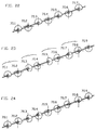
- successive pairs of cams 70.1, 70.2, etc. are arranged at 180° relative to each other to induce a decubitis action in use.
- a first pair of cams 70.1, 70.2 are arranged at 0° and 180° on an axis of rotation of the shaft 73 respectively.
- a second pair of cams 70.3, 70.4 are arranged at 45 ° and 225° respectively.
- a third set of cams 70.5 and 70.6 are arranged at 90° and 270° respectively.
- a fourth set of cams 70.7 and 70.8 are arranged at 135° and 315° respectively. The arrangement of said pairs of cams 70.1 to 70.8 induce a combined decubitis and travelling wave action in use.
- a single formation e.g. a moulding, extending the full length of the cams 70.1 to 70.2 integrally, could be provided; this could be fitted on the shaft or constitute the shaft itself.
- slats may be operated in pairs so that a wider support is provided; narrow slats, e.g. 5 cm wide, may be provided for a more marked effect, for some applications, or operated in pairs to give a wider support, e.g. 10 cm., for a "gentler" effect, for other applications.
- Figure 25 shows a longitudinal section of an apparatus similar to that shown in figure 1 wherein pivotable pairs of channels 76.1 and 76.2 are arranged towards opposing ends of a longitudinal member 78 of the frame 1.
- the beams 2 extend transversely between and interconnect each pair of channels 76.1 and 76.2 which are pivotable between and inclined position as shown in figure 30 and a declined position wherein the beams 2 engage and are manipulated by the cams 4. 1 located towards opposing ends of the shaft 3.
- Retaining linkages 77 which extend between the channels 76 and the longitudinal members 78 are provided to releasably retain the channels 76 in the inclined position.
- a frame 79 which carries beams 2 and a shaft and cam assembly (not seen) has pivotable end portions 81.
- Portions 81 are each only a frame and stretched fabric or other comfortable support and are folded up leaving the beams and shaft still flat in the frame.
- Figure 27 shows a longitudinal section of a portion of an apparatus wherein an inclined footrest 84 which carries a shaft and cam assembly 85 for manipulating beams 2 carried by the footrest 84 is provided at an end of the frame 1.
- the shaft 3 and shaft and cam assembly 85 are rotatably connected by a universal coupling joint 82.
- Figure 28 shows a beam 88 similar to that of beam 2 shown in figure 2 wherein zones of flexibility 89 are provided on either side of a cam follower 90.
- the zones of flexibility 89 are provided by reducing the thickness of the beam 88 in said zones.
- the stiffer parts 88a can be one or more flanges.
- a slot 88b locates it at one end in a bed frame.
- a wearing pad 90b can have different thicknesses to adjust the levels at which the beam oscillates or spacers 127 of differing thicknesses; the beam may have holes to clip them in place. Spacers 128 could alternatively be put on top of the beam.
- Figure 29 shows an integral beam 92 having a base portion 93 of similar form to beam 88 and a support portion 94 mounted thereon.
- a pair of post and spring assemblies 95 similar to that shown in figure 19 urge the support portion 94 towards an inoperative biased position as shown in figure 34.
- the post and spring assemblies 95 are disengaged to permit the support portions 94 to be displaced towards the base portion 93 so as to conform to the profile of a prone body supported thereby.
- the post and spring assemblies 95 are then locked in position in similar manner to that described with reference to figure 17.
- Figure 30 shows a portion of an integrally formed planar support member 97 having parallel beams 98 which are defined by a sinuous slot 99.
- the beams 98 are arranged to extend alternately from opposing longitudinal sides 100 and 101 of the support member 97.
- the support member 97 is configured to extend between and interconnect the longitudinal members of the frame 1.
- Figure 31 shows a planar support member 102 similar to that of support member 97 wherein expandable biasing connectors 103 extend between end portions 104 of alternately arranged beams 105 and the longitudinal sides 100 and 101.
- the connectors 103 include generally ring shaped parts and arms which extend diametrically from the ring shaped parts to interconnect the longitudinal sides 100 and 101 and the beams 105. In operation, as the beams 105 are displaced towards a lower position, so the ring shaped parts expand to allow the beams 105 to follow the profile of the cams.
- figures 32 and 33 show planar support member 107 where expandable biasing connections are provided by generally U-shaped formations 108 which are spring biased so as to act in similar manner to the connectors 103 already described.
- Figure 34 shows an end view of an apparatus wherein there is provided pivotable limiting members 109 which extend along the length of the frame 1.
- the members 109 are pivotally displaceable in the direction of arrows 110 so as to limit the deflection of the beams 88 in use.
- actuating arms are provided to displace said members 109.
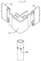
- Figure 35 shows the corner piece 118 has a circular section bore 125 defined therethrough for receiving legs 126 of the frame 1 and a head board frame or side frames (not shown) for retaining a patient on the apparatus.
- the tubes can support a headboard of the bed for clip boards and/or traction equipment.
- Figure 36 shows a sectional view of longitudinal and transverse frame members 78 of the frame 1, which has channel formations 111 and 112 for receiving and retaining a closure plate 113 and support members 114 for supporting the shaft 3 in bearings 115,
- the bearings 115 are open topped to allow easily lifting out of the shaft 3, e.g. to re-arrange the cams on it for the bed to serve a new purpose.
- a channel 116 is configured to receive a complementary locating formation 117 (Fig. 38) of a corner piece 118 as shown in figure 38.
- a down turned web 119 allows a connecting member 120 having a hooked portion to retain a foamed strip 127 conforming to the width of the beams 88 thereon.
- the hook could alternatively be hooked onto the beam 88.
- the locating formation 117 has tongue formations 121 which engage an inner face of a web 119 and an inner face of a flange 122 of the member 78.
- Transverse cross members which extend transversely between the longitudinal members 78 have similar profiles to that of the longitudinal members 78. The transverse cross members are connected to the corner member 118 in similar fashion to that of the longitudinal members 78.
- Figure 37 shows how the corner piece 117 joins a longitudinal member 78 and transverse member 78a as well as a leg 126. These connections are made at each of the four corners to form the frame.
- the apparatus described in this specification can be built into a divan, or domestic bed, so that the private owner can save space and have two uses, one as a conventional divan with a mattress on top of the beam, and otherwise for massaging/decubitus.
Abstract
Description
- Bed sores, also called decubitis ulcers or pressure sores are an area of disintegrating skin and underlying tissue or ulcer resulting from decreased blood supply to that area and affecting persons who have been bedridden for a long period of time.
- Specially designed beds are intended to mitigate this problem. United States
patent 4 999 861 andItalian patent 122 0502 are examples of the art in this field. The present invention may also be applied to chairs, e.g. wheelchairs for paraplegics, and divans. - Apparatuses of this kind have suffered in many of the proposals from undue complexity in mechanical construction and arrangements. This disadvantage leads in general to a high cost for the apparatus thus imposing a severe limitation on the generality of its potential application.
- The art also has reported adverse effects from the application of treatment using these kinds of apparatus. These effects have been reported as a fatigue, vertigo and even nausea resulting from long periods of treatment with the apparatus. These adverse side effects naturally discourage the use of the apparatus in the treatment of decubitis ulcers or the reduction of their incidence.
- A main feature of the present invention has thus been directed to the provision of an apparatus which allows the main effects to be achieved nevertheless with a manufacture and construction which can be inexpensive, light and uncomplicated.
- Thus in accordance with the invention there is provided apparatus of this kind for support of the body which comprises a plurality of flexible beams which extend transversely and parallel to each other and adjacent to one another, supported at their ends and having a shaft running longitudinally and orthogonally to the beams and underneath them, the shaft having a plurality of cams mounted on it, the cams engaging at least some of the beams and adapted so that upon rotation of the cams the beams are flexed by the cams to be alternatingly raised or alternatingly lowered, or both alternatingly raised and lowered.
- Thus, for example, in the application to an apparatus which provides support in a manner analogous to a bed, whether entirely in a prone position or in a partly reclining position, the beams extend transversely from one side to the other. The single shaft is preferably located generally centrally, and running longitudinally. The shaft may be adapted to be rotated from time to time manually so as to bring one set or other of the beams into a supporting position and to lower the other set to provide for the restoration of circulation in the body surfaces opposite that set of beams. Alternatively the shaft may be adapted to be rotated by an electric or other motor with a suitable gearing. The rotation in accordance with the invention may be selected either to be continuous at a fairly slow rate or intermittent. Where intermittent motion is required this can be provided by a suitable controller and stepping motor.
- In accordance with the invention the flexible beams are leaf springs, one end being secured to a frame of the apparatus and the other end being enclosed but free to move longitudinally to a limited extent as the leaf-spring-like beam flexes under action of the cam acting on it.
- As an alternative structure to the use of flexible beams which are in the nature of leaf springs, each beam may be articulated near its mid length, one or both ends then being enclosed but free to move longitudinally to a limited extent when the beam articulates under action of the cam, the other end being secured.
- Preferably in either event the beams are provided with cam following surfaces so that the cams may have sliding contact with the surfaces of the beam, these surfaces being of low friction co-efficient material. Preferably the cam following surfaces are in the form of a replaceable wear pad.
- As an alternative the cams can be provided to act on roller type followers which are provided on the beam.
- The levels of the beams may vary in accordance with a profile in the longitudinal direction, as is desired for support of the prone body.
- In order to achieve this the effective depth of the cam followers on successive beams may be selected so as to vary according to a desired longitudinal profile of the dorsal part of the human body. In this way the development of above average pressure on prominences of the dorsal profile of the body may be avoided.
- It is another important feature of the invention that the cams will be selected so that the alternating movement of the beams does not result in the body being raised and lowered alternatingly. Instead the cams will be selected so that the beams provide for a support of the body at a constant level with alternating sets of the beams lowering to a position in which they remove pressure from the body tissues in the areas opposite that set of beams. In this way by avoiding cams which generate alternating upwards and downwards movement of the body it is possible to avoid the deleterious effects which have been reported in the art.
- The potential for the apparatus to adapt to the longitudinal dorsal profile of the prone human body or the other profiles of the body, for example, the sides and if required the ventral profile can be provided by a special optional feature of the invention. This is the provision of the cam carrying longitudinal shaft in the form of a flexible cable able to flex while rotating. The cable is mounted rotatively in journals which are sprung mounted on a base or frame of the apparatus. The journals thus may yield differentially to different loads along the length of the apparatus and so accommodate the profile of the body by virtue of the flexibility of the shaft.
- The sprung mounting of the journals which carry the flexible shaft may be achieved, for example, by means of a coil spring under each journal, with suitable locating mechanisms provided. As an alternative to a coil spring a transverse leaf spring will have the advantage of providing both the flexibility of support of the journals for the flexible shaft and also will tend to the locate them sufficiently.
- Preferably the shaft has a non circular cross sectional shape extending uniformally in the length of the shaft so that the cams can be slid along the length of the shaft to required positions but held irrotationally.
- Where the cross sectional shape has a polygonal symmetry this allows the cams which have a hole fitting that cross sectional shape of the shaft to be fitted on to the shaft in any one of the plurality of a angularly separated positions. This allows for the adaptation of the apparatus in a number of alternative ways in accordance with this invention. In particular, for example, for the purpose of treatment to reduce the tendency for development of decubitis ulcers the cams will be provided, for example, alternatingly fitted on to the shaft at 180° rotation relative to each successive cam.
- A final, and important feature of the invention rests on a discovery that the apparatus, although it could be regarded as one having the purpose of preventing decubitis ulcers can, with careful adaptation, be suitable for the application of relaxing massaging. With this invention the massaging can avoid the problems of the prior art devices of recorded experiences of adverse physiological and psychosomatic effects such as fatigue, vertigo and nausea. It has furthermore been established that the massaging action, as will be described below, can have a simultaneous decubitus prevention effect in suitable cases.
- Thus in accordance with this preferred embodiment of the invention the cams on the shaft are angularly oriented in successive positions along the length of the shaft so as to induce in the surface presented by the beams the effect of a travelling wave when the shaft rotates, the wave travelling longitudinally along the length of the apparatus and having a flat top to the wave form. The wave will preferably travel from the foot to the head of the bed to enhance venous blood circulation in a person lying on the bed.
- In order to understand conceptually how this can be achieved by a suitable orientation of the cams the example can be considered where each successive cam of the kind shown in figures 6 to 8 is angularly oriented clockwise with respect to the preceding cam, as one proceeds along the length of shaft, by a constant specified angle such, for example, as 45°. With this arrangement every 8th cam will then be oriented angularly the same as the first cam and the beams in between will be raised by the cams to follow a flat top sinusoidal wave form proceeding longitudinally along the apparatus. It may be desirable for this form to be attained by a larger number of cams or over a longer distance, in which case the successive orientation would be a smaller number of degrees between successive cams than 45, e.g. 30°. Alternatively, the successive orientations may be by a larger angular difference. When the shaft is rotated with the cams oriented in this way the sinusoidal wave form presented longitudinally along the apparatus by the successive beams appears to travel along the length of the apparatus. This has been found to have a calming effect on a person resting on the apparatus also relaxing the patient. The length of time which this must be carried out is limited and may vary, for example, between 5 minutes and 30 minutes, preferably being between 10 mins and 20 mins. A timer is preferably provided on the apparatus to allow setting the time of operation. Because of the undulating travelling wave effect a soothing impression is created on the body rather than an impression which in time becomes adverse. The invention includes apparatus in which these arrangements have been provided for. The wave may travel at 2,4 meters per minute with the shaft rotating at 4 r.p.m.
- The effects described above have been observed in tests in a hospital in Udine, Italy. Apart from a sinusoidal wave form any other wave form in principle can be provided for and certain wave forms can be designed to have particular therapeutic effect. For example a wave form which comprises an asperity at the peak of the form can be adopted to provide a more acute massage or a wave form having a steeper rising part than its lowering part, for example.
- The tests which have been performed with prototypes of the apparatus in accordance with this invention in the massaging application, that is for purposes of relaxation and improvements to the blood and lymphatic circulation have revealed an important new result. In accordance with this aspect of the invention the preferred wave form which is produced by the cams selected for the shaft and their relative angular orientation with respect to each other is a wave form which may be described as a flat topped wave form. This wave form is a further novel feature in the art and it has the advantage that instead of a wave form advancing along the length of the bed which has a peak or moderate asperity, in accordance with this invention the top of the wave form is a flat plateau whereas the bottom part of the wave form may follow, for example, a sinusoidal shape. The portion of the wave which takes the main support of the body and thus produces the main pressure on the body is a shape which provides a distributed pressure over the body instead, as mentioned, a peak. The result is a lower distributed pressure on the body and it is believed that this has a more favourable effect in improving circulation and because there is less localised pressure the massage is more relaxing.
- The mechanical arrangement in which this type of wave form is produced is achieved in accordance with the invention by the use of cams which have a sector of the cam profile which may vary between, for example, 90° and 180° of constant radius measured from the axis of rotation of the cam, the remaining sector being of a reduced radius to provide the low part of the wave form on the bed. Further in accordance with this aspect of the invention the relative angular advance from one cam to the next cam along the length of the cam shaft and thus also along the length of the bed is selected with due consideration of the angle of constant radius of the cam profile. Thus, for example, if the cam profile has a portion of constant radius of 120° then the angle of advance of each cam to the next successive adjacent cam may be selected at 30°. This means that a plateau is created which is flat over the length of four cams along the length of the shaft because all of these will still be presenting the sector of constant radius. Beyond these four cams if the angular advance of 30° is maintained there will be eight cams which provide the wave form moving from the plateau downwards in an approximation at least of a sinusoidal wave shape. Of course, the angular advance from one successive cam to the next need not necessarily be maintained at 30° along the full length of the wave form, as an alternative in accordance with the invention. Also naturally any other angle of advance than 30° may be selected, this being merely a convenient example. Thus in this way the proportion of the total wave length which has the flat plateau can be selected in accordance with the invention.
- In accordance with the invention the shaft has a non-circular section or, for example, a polygonal section and a simple convenient one is a square cross section which can be provided inexpensively in a hollow square section tube. The bore of each of the cams which fits on that shaft may in fact be a serrated or toothed shape having 12 indentations so that the cam can be fitted on to the shaft in any of one of 12 different orientations. This means that using a constant cam profile each successive cam can easily be mounted on such a shaft with a 30° advance relative the preceding adjacent cam. Thus in a convenient and inexpensive way achieve the objects of this feature of the invention of a flat top or plateau type of wave profile along the length of the bed.
- Not only that but the cams can easily be slid off the shaft and reoriented so that each cam is 180° advanced with respect to the preceding cam and this can provide, for example, with cams where the portion of constant radius is 180°, a decubitis action provided by the cam. In this action alternate beams actuated by the cams will lower so as to provide a relief of the support and pressure on the body in the classical decubitis action, but without raising and lowering the body. Hence the same apparatus can be adapted to both of these purposes.
- Again this wave type of massage can be implemented using a rigid shaft running longitudinally or a flexible cable type shaft running longitudinally.
- The invention will be more fully described by way of examples with reference to the accompanying drawings, in which :
- Figure 1 is a plan view of apparatus in accordance with a preferred embodiment of the invention, shown schematically,
- Figure 2 is an enlarged transverse sectional elevation of the apparatus shown in figure 1,
- Figure 3 is a partial view of an alternative transverse beam,
- Figure 4 is a partial elevation of a further alternative transverse beam,
- Figure 5 is a transverse sectional elevation of a shaft and cam,
- Figure 6 is a further elevation of a cam,
- Figure 7 is a further elevation of an adjacent cam,
- Figure 8 is an elevation of the two cams as they are mounted on the shaft, for decubitus,
- Figure 9 is a plan view on an alternative shaft,
- Figure 10 is a transverse sectional elevation on an alternative beam,
- Figure 1 1 is a side view schematically of a shaft, cams and beams,
- Figure 12 is a similar view on a shaft and cams with alternative beams having differing thickness cam followers,
- Figure 13 is again a similar side elevation of a shaft, cams and beams where the shaft is a flexible kind,
- Figure 14 is a transverse sectional elevation on a flexible shaft, cams and beams,
- Figure 15 is a similar transverse sectional elevation of flexible shaft in an alternative arrangement,
- Figure 16 is a side view and end view of a flexible shaft,
- Figure 17 is a side elevation of an alternative form responsive arrangement of beams,
- Figure 18 is a side elevation showing a wave form that can be generated for relaxation therapy, (and can have a decubitus effect);
- Figures 19 to 21 show elevations of three preferred cams as they are mounted on a shaft;
- Figures 22 to 24 show three dimensional views of portions of four cam and shaft assemblies;
- Figures 25 to 27 show sectional side views of three preferred apparatuses;
- Figures 28 and 29 show transverse elevations of two further transverse beams;
- Figures 30 to 32 show plan views of three alternative planar support members;
- Figure 33 is a side view of a part of the planar support member shown in figure 32 taken along
lines - Figure 34 is an end view of an apparatus incorporating a limiting device for limiting the deflection of the beams;
- Figure 35 is a plan view of a corner piece of a frame;
- Figure 36 is an elevation of a profile of a longitudinal member to be used with the corner piece shown in Figure 38; and
- Figure 37 shows a corner assembly of the frame.
- As shown in figures 1 and 2 the apparatus comprises a rigid
rectangular frame 1 in which the operating parts are mounted. A plurality offlexible beams 2 which span the transverse dimension of theframe 1 extend transversely and parallel to each other and adjacent one another. They are supported at their ends by the frame. Theshaft 3 runs longitudinally in theframe 1 and thus orthogonally to the beams and is located underneath them. In the view of figure 1 only a small number of beams is shown so as to be able to illustrate the shaft and sufficient beams will be provided to cover the entire upper surface enclosed within theframe 1. Theshaft 3 has a plurality ofcams 4 on it and again only a few cams are shown by way of illustration, one cam in fact being provided for every beam and thus extending along the full length of the shaft. The shaft is journaled at 5 and 6 and a pulley 7 allows for a connection by means in this example of a V-belt 8 to a pulley 9 of an electric motor 10 with gearbox which rotates either at an appropriate continuous feed or intermittently. The motor could alternatively be direct coupled through a suitable gearbox. Atimer 10a controls the motor to a preset duration or even for a programmed sequence of operations over 24 hours, e.g. per a doctor's prescription. - As shown in more detail in the view of figure 2 the
beam 2 has acam following surface 11. This can have replaceable wear pads of polytetrafluoro ethylene (PTFE). One end of each beam has anotch 12 which fits into a down turnedweb 13 of aninverted channel formation 14 of theframe 1 while theother end 15 of thebeam 2 is free to move longitudinally as indicated by thearrows 16 to a limited extent being retained at its end by means again of theinverted channel 17 of the frame. This allows the same type of frame members to be used all around the frame. Thebeam 2 is made of a flexible material and so functions somewhat like a leaf spring. The beam may be a steel leaf surrounded by a suitable plastic coating to make it more appropriate as a support for a thin mattress of a bed which this example provides. The beam may be made of plastic material, e.g. injection moulded. The anchored ends of the beam alternate on left and right longitudinal sides of the frame. The beam presents a slightly concave upper surface, but could alternatively be flat. - Figure 3 shows that the
beam 2 could alternatively be articulated at itscentre position 18, eachhalf - Figure 4 shows one slightly different arrangement where the
articulation point 21 is not in the centre of the beam but somewhat to one side. - Figure 5 shows one preferred arrangement of the
shaft 3, this having four longitudinally runninggrooves cam 4 having a hole which has projections in the hole which match these grooves. This allows the cam to be slid on to the shaft to any longitudinal position along the length of the shaft but to be irrotationally held. It also allows the cam to be slid on to the shaft in any one of four angularly differentiated orientations as will be necessary in order to perform the various functions of which the apparatus is capable as has been described heretofore. As an alternative the shaft could be of square section, either hollow or solid, or it could have a larger number of grooves. - Thus for the use of the apparatus to avoid decubitis ulcers and wave therapy cam arrangements are shown in figures 6 to 8.
- Figure 6 shows a
first cam 26 and the next following cam on the shaft 27, the cam after the cam 27 being arranged as thecam 26, and so on alternatingly. - Figure 8 thus shows the
cams 26 and 27 (all the other cams alternating in a similar relationship) on theshaft 3. It will be seen that thesurfaces cams 26 and 27 respectively together combine to form a circle that is of constant radius. The other twosurfaces portions surfaces - In this way movement which would cause the body to oscillate upwards and downwards is avoided and this is found to be important to avoid any feeling of nausea, vertigo or fatigue or at least to reduce the tendency of those feelings developing to a large extent, if not to entirely eliminate them. At the same time the alternating locations on the body have pressure removed from them so as to restore circulation. For this reason the timing of the movements would be appropriate as is recorded to physiological needs of the body for the restoration of circulation in the alternating position. Thus an electric motor driving the shaft could in fact be a stepping motor controlled by a suitable controller so that the shaft rotates through 180° then stops for a period sufficient for recovery of circulation, then rotates a further 180° and so on. These time periods may be in the region of 8 to 30 minutes, for example.
- Figure 9 shows the shaft in the case where the
grooves 22 to 25 follow a spiral form rather than being straight. This shaft can be used particularly, for example, to obtain the effects which will be described with reference to figure 18. - Figure 10 shows a transverse cross sectional elevation showing upper parts of the
frame 1 and a flexible supportingbeam 32 which is articulated only at oneend 33 at theframe 1, theother end 34 being free. The result is that thecam 4 rotating on theshaft 3 again periodically lowers thebeam 32 for the effects described. - Figure 11 is a side schematic elevation of the apparatus in which the plurality of
beams 2 can be seen with thecams 4 on theshaft 3. Again for ease of illustration only a few cams are shown but one cam would be provided for every beam. This shows the alternating arrangement in which evenly numbered beams, numbering from one end, are at a level which is the consistent level of support of the body while odd numbered beams, e.g. 2' have dropped down to a lower level so as to remove pressure from the body tissues at each of these beams 2'. Thus half the beams are at the level of support and the other half have moved downwards to remove pressure on the tissues. As theshaft 3 continues to rotate the odd numberedbeams 2 then lower and the evenly numbered beams 2' raise to the level of the body. This thus alternates as has been described the pressure on the body tissues. This is thus designed to achieve the avoidance of decubitis ulcers. - Figure 12 shows another embodiment of the invention in which the
shaft 3 andcams 4 are as has been described up to now but each of thebeams 2 has a beam follower of a selected thickness as is indicated. The selection of the thickness is adapted to provide for an accommodation of the contours of the human body as is shown by theline 32. This can provide a greater comfort of support for the individual, and reduced pressure on prominences. - Figure 13 shows an extension of this idea of adapting to the dorsal profile of the prone human body in an entirely flexible way which will react to the profile of each different individual. Here the
shaft 33a is in fact a flexible cable. It is journaled at itsends pulley 36 by way of example to rotatively drive the flexible shaft. At the position of mounting of the pulley the shaft can be made rigid. The shaft again carries a plurality ofcams 4 which may be of the kind which has been described heretofore. Along the length of theshaft 33a a plurality ofjournals 36, which may be ball races in suitable housings, are supported bysprings 37. Thus an elastic support for theflexible shaft 33a is provided and accordingly it is able to yield to the pressure provided by prominences in the dorsal profile of the prone human body. This thus is analogous to a sprung support for the human body and it allows a more comfortable posture to be arrived at. At the same time, once the shaft rotates the alternating support between even and odd numbered transverse beams so as to avoid decubitis ulcers development is also achieved. This arrangement is also shown in figure 14 in which it can be seen in theframe 1 with thebeams 32 articulated at 33 withends 34 by way of example (the other beams as shown, for example, in figures 2 to 4 could alternatively be used). On theflexible shaft 33 can be seen one of thecams 4 working on thecam follower 11. Around theshaft 33 can be seen the journal 36 (which could also be a lubricated bush and journal arrangement) thejournal 36 then has a foot piece or base on to which thecoil spring 37 presses, the coil spring being located bystructure 38 on thebase 39 of theframe 1. Transverse location of thejournal 36 could be provided by an articulatedarm 40 fixed to one side of theframe 1 and fixed to thejournal 36. - Figure 15 shows an alternative arrangement in which the parts are similar except that instead of the
coil spring 37 there is provided aleaf spring 41 which extends between the sides of theframe 1. Thejournal 36 is fixed on to theleaf spring 41 and again it may be fixed at one end to theframe 1 while the other end is contained in a slot but slidably to allow limited transverse movement of that end of the leaf spring as it flexes. - Figure 16 is a side elevation and end view of a
flexible shaft 33. This is in fact a cable laid up with a core 42 with fourstrands 43 to 46 laid around thecore 42 equally spaced from each other. This provides thus a cross sectional shape for the shaft in which again analogously to the rigid shaft which has been described with reference to previous figures; the cams can be slid along the length of the shaft. Because of the helical nature of the lay this flexible shaft will inherently have the helical aspect which was described as an option with respect to the rigid shaft with reference to figure 9. Even with this helical aspect the shaft can be rotated intermittently by a suitably timed stepping motor in order to achieve the avoidance of decubitis ulcer. - When such a shaft is rotated continuously, however, the effect on the transverse beams is that actually of a travelling wave.
- Figure 17 shows a structure in which inherent potential for adjustment to the profile of a prone body on the apparatus is provided. Each of the
transverse beams 47 is of tubular form and contains within it a slidingrod 48. Each beam carries a plurality ofupright posts 49, each of which presents a supportingpad 50 for the human body. Coil springs 51 tend to keep theseposts 49 in the upright position at an upper position established by the ring clips 52. On one side of theposts 49 there is provided atoothed rack 53. The slidingrod 48 has a number of holes through which theupright posts 49 pass and these are slotted holes with one side of the holes having atoothed formation 54 which is complimentary to theteeth 53. When theshaft 48 is moved to the left as indicated by thearrow 55 in all of thetransverse beams 47 the person is placed or gets on to the apparatus lying in a prone position, for example, dorsal side down most. As a result of thesprings 51 each of thesupports 50 then are pressed downwards to a degree dependent on the dorsal profile of the person and the distribution of weight in the body. Once the person is settled in a comfortable position theshaft 48 is moved to the right as indicated by thearrow 56 and theteeth 54 then lock into theteeth 53 locking the apparatus in this position. The movement of theshaft 48 is provided by a lever 57 which is connected in a suitable way (not shown) to ahandle 58 by which all of therods 48 are moved to the locked position or the unlocked position as required. - Figure 18 indicates with the
line 60 a typical wave motion which will be adopted by the beams when the shaft is of the helical kind so that each cam is angularly rotated relative to the previous through a suitable angle. This means that the level of the beams follows theline 60 and once the shaft is rotated thewave form 60 then appears to travel in a longitudinal direction either to the right or the left. The preferred wave form is approximately sinusoidal with a flattened wave top 60a; this wave form is provided by the cams of the shape shown in, and described with reference to figures 6 to 8. This travelling wave has been found to provide a valuable relaxation therapy which does not tend to the provision of effects such as fatigue, vertigo or nausea as has been reported in the prior art. Nevertheless, the operation of the apparatus to provide a relaxation therapy is preferably selected at the time of between 1 and 30 minutes or preferably between 5 and 20 minutes. More preferred time periods are between 5 and 30 minutes, between 5 and 20 minutes or most of all between 10 and 20 minutes. The rate of movement of the travelling wave may, for example, be between 25 and 100 mm per second, more preferably between 40 and 60 mm per second, i.e. 1,4 m per minute. These aspects can be adjusted in the discretion of the physician according to the individual. - Figure 19 shows a
cam 70 having a profile similar to that ofcam 26 shown in figure 5 for inducing a decubitis action. In this particular embodiment abore 71 having twelveserrated indentations 72 is defined in thecam 26 to receive asquare section shaft 73 in rotatably therethrough. Theindentations 72 permit thecam 70 to be arranged in any one of twelve angularly differentiated orientations between 0° and 330° advanceable in increments of 30°. Th cam has a fixed radius R over 180° and a reduced radius over the rest. - Figures 20 and 21
show cams beams 2. In particular,cam 74 has a sector of constant radius 76 of 120°.Cam 74 has a fixed radius R over 120°, the remainder being of reduced radius.Cam 75 has a generally oval profile. - In figure 22, successive pairs of cams 70.1, 70.2, etc. are arranged at 180° relative to each other to induce a decubitis action in use.
- In figure 23, a first pair of cams 70.1, 70.2 are arranged at 0° and 180° on an axis of rotation of the
shaft 73 respectively. A second pair of cams 70.3, 70.4 are arranged at 45 ° and 225° respectively. A third set of cams 70.5 and 70.6 are arranged at 90° and 270° respectively. A fourth set of cams 70.7 and 70.8 are arranged at 135° and 315° respectively. The arrangement of said pairs of cams 70.1 to 70.8 induce a combined decubitis and travelling wave action in use. - In figure 24 the
successive cams - It will be appreciated that instead of a plurality of cams as used in any of figures 22 to 24 a single formation, e.g. a moulding, extending the full length of the cams 70.1 to 70.2 integrally, could be provided; this could be fitted on the shaft or constitute the shaft itself. In general slats may be operated in pairs so that a wider support is provided; narrow slats, e.g. 5 cm wide, may be provided for a more marked effect, for some applications, or operated in pairs to give a wider support, e.g. 10 cm., for a "gentler" effect, for other applications.
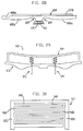
- Figure 25 shows a longitudinal section of an apparatus similar to that shown in figure 1 wherein pivotable pairs of channels 76.1 and 76.2 are arranged towards opposing ends of a
longitudinal member 78 of theframe 1. Thebeams 2 extend transversely between and interconnect each pair of channels 76.1 and 76.2 which are pivotable between and inclined position as shown in figure 30 and a declined position wherein thebeams 2 engage and are manipulated by thecams 4. 1 located towards opposing ends of theshaft 3. Retaininglinkages 77 which extend between the channels 76 and thelongitudinal members 78 are provided to releasably retain the channels 76 in the inclined position. - In figure 26, a
frame 79 which carriesbeams 2 and a shaft and cam assembly (not seen) haspivotable end portions 81.Portions 81 are each only a frame and stretched fabric or other comfortable support and are folded up leaving the beams and shaft still flat in the frame. - Figure 27 shows a longitudinal section of a portion of an apparatus wherein an
inclined footrest 84 which carries a shaft andcam assembly 85 for manipulatingbeams 2 carried by thefootrest 84 is provided at an end of theframe 1. Theshaft 3 and shaft andcam assembly 85 are rotatably connected by a universal coupling joint 82. - Figure 28 shows a
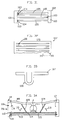
beam 88 similar to that ofbeam 2 shown in figure 2 wherein zones offlexibility 89 are provided on either side of acam follower 90. The zones offlexibility 89 are provided by reducing the thickness of thebeam 88 in said zones. Thestiffer parts 88a can be one or more flanges. Aslot 88b locates it at one end in a bed frame. A wearing pad 90b can have different thicknesses to adjust the levels at which the beam oscillates orspacers 127 of differing thicknesses; the beam may have holes to clip them in place.Spacers 128 could alternatively be put on top of the beam. - Figure 29 shows an integral beam 92 having a base portion 93 of similar form to
beam 88 and asupport portion 94 mounted thereon. A pair of post andspring assemblies 95 similar to that shown in figure 19 urge thesupport portion 94 towards an inoperative biased position as shown in figure 34. In operation the post andspring assemblies 95 are disengaged to permit thesupport portions 94 to be displaced towards the base portion 93 so as to conform to the profile of a prone body supported thereby. The post andspring assemblies 95 are then locked in position in similar manner to that described with reference to figure 17. - Figure 30 shows a portion of an integrally formed
planar support member 97 havingparallel beams 98 which are defined by asinuous slot 99. Thebeams 98 are arranged to extend alternately from opposinglongitudinal sides support member 97. Thesupport member 97 is configured to extend between and interconnect the longitudinal members of theframe 1. - Figure 31 shows a
planar support member 102 similar to that ofsupport member 97 whereinexpandable biasing connectors 103 extend betweenend portions 104 of alternately arrangedbeams 105 and thelongitudinal sides connectors 103 include generally ring shaped parts and arms which extend diametrically from the ring shaped parts to interconnect thelongitudinal sides beams 105. In operation, as thebeams 105 are displaced towards a lower position, so the ring shaped parts expand to allow thebeams 105 to follow the profile of the cams. - Similarly, figures 32 and 33 show
planar support member 107 where expandable biasing connections are provided by generallyU-shaped formations 108 which are spring biased so as to act in similar manner to theconnectors 103 already described. - Figure 34 shows an end view of an apparatus wherein there is provided pivotable limiting
members 109 which extend along the length of theframe 1. Themembers 109 are pivotally displaceable in the direction ofarrows 110 so as to limit the deflection of thebeams 88 in use. Although not shown, actuating arms are provided to displace saidmembers 109. - Figure 35 shows the
corner piece 118 has a circular section bore 125 defined therethrough for receivinglegs 126 of theframe 1 and a head board frame or side frames (not shown) for retaining a patient on the apparatus. The tubes can support a headboard of the bed for clip boards and/or traction equipment. - Figure 36 shows a sectional view of longitudinal and
transverse frame members 78 of theframe 1, which haschannel formations closure plate 113 andsupport members 114 for supporting theshaft 3 inbearings 115, Thebearings 115 are open topped to allow easily lifting out of theshaft 3, e.g. to re-arrange the cams on it for the bed to serve a new purpose. (See also Figure 34.) Achannel 116 is configured to receive a complementary locating formation 117 (Fig. 38) of acorner piece 118 as shown in figure 38. A down turnedweb 119 allows a connectingmember 120 having a hooked portion to retain a foamedstrip 127 conforming to the width of thebeams 88 thereon. The hook could alternatively be hooked onto thebeam 88. The locatingformation 117 hastongue formations 121 which engage an inner face of aweb 119 and an inner face of aflange 122 of themember 78. Transverse cross members which extend transversely between thelongitudinal members 78 have similar profiles to that of thelongitudinal members 78. The transverse cross members are connected to thecorner member 118 in similar fashion to that of thelongitudinal members 78. - Figure 37 shows how the
corner piece 117 joins alongitudinal member 78 andtransverse member 78a as well as aleg 126. These connections are made at each of the four corners to form the frame. - The apparatus described in this specification can be built into a divan, or domestic bed, so that the private owner can save space and have two uses, one as a conventional divan with a mattress on top of the beam, and otherwise for massaging/decubitus.
Claims (11)
- Apparatus for support of the body, which apparatus has a frame constituting one selected from a bed, divan, chair or wheelchair, having a plurality of beams extending parallel and adjacent to each other transversely across the frame to form a support for the body, with cam means below the beams, motor driven to cause rotation of the cam means which acts on the beams to cause the beams to be raised and lowered alternately, which apparatus is characterized in that the beams (2) are flexible , supported at their ends (13,15) and have a single shaft (3) running longitudinally and orthogonally to the beams and underneath them, having a plurality of cams (4) mounted on the shaft, the cams engaging at least some of the beams and adapted so that upon rotation of the cams the beams are flexed by the cams to be alternatingly raised or alternatingly lowered or both alternatingly raised and lowered.
- Apparatus as claimed in claim 1, characterized in that the beams are elastic beams in the nature of leaf springs, one end (13) being secured (12,14) to the frame and the other end (15) being enclosed but free to move longitudinally to a limited extent (16) in the frame (17) as the beam or leaf flexes under action of the cam acting on it.
- Apparatus as claimed in claim 1, characterized in that the beam (19,20) is articulated (18) near its mid length, one or both ends being enclosed but free to move longitudinally to a limited extent when the beam articulates under action of the cam.
- Apparatus as claimed in any one of claims 1 to 3, characterized in that the beams have sliding contact inserts (90) replaceably fitted to an under surface of each beam, suitably located to be acted on by the cams.
- Apparatus as claimed in any one of claims 1 to 4, characterized in that the sliding contact inserts (90) are provided themselves or with spacers (127) in a range of thicknesses so that they may be selected for fitting to beams so that the levels of the beams vary according to a profile in the longitudinal direction desired for the support of the prone body.
- Apparatus as claimed in any one of claims 1 to 4, characterized in that the longitudinal shaft (33a) carrying the cams is a flexible cable able to flex while rotating, the cable mounted rotatively in journals (36) which are sprung mounted (37) on a base or the frame, so that the journals may yield differentially to different loads along the length of the apparatus and so accommodate the profile of the body.
- Apparatus as claimed in any one of claims 1 to 6, characterized in that the cams on the shaft are angularly oriented in successive positions along the length of the shaft so as to induce in the surface presented by the beams the effect of a travelling wave (60) when the shaft rotates, travelling longitudinally along the length of the apparatus, the cam profiles being selected so that the wave form has a flat top (60a).
- Apparatus as claimed in claim 7, characterized in that the shaft is a hollow square tube (73) and the cams (70) each have twelve serrated indentations allowing the cams to be fitted to the shaft in twelve different positions irrotational with respect to the shaft.
- Apparatus as claimed in any one of claims 1 to 8, characterized in that the frame has end portions (76.1,76.2;81,81)) which can be folded up from the level of the remaining part of the frame, leaving the cams and shaft still at the level of the remaining part of the frame.
- Apparatus as claimed in claim 9, characterized in that in addition the beams are also left still at the level of the remaining part of the frame.
- The use of an apparatus as claimed in claim 7, in a method of relaxation, characterized in that a travelling wave is induced in the support surface for a person and is operated for a time period of from 5 to 30 minutes.
Applications Claiming Priority (2)
| Application Number | Priority Date | Filing Date | Title |
|---|---|---|---|
| ZA9600993 | 1996-02-08 | ||
| ZA96993 | 1996-02-08 |
Publications (3)
| Publication Number | Publication Date |
|---|---|
| EP0788786A2 true EP0788786A2 (en) | 1997-08-13 |
| EP0788786A3 EP0788786A3 (en) | 1998-01-14 |
| EP0788786B1 EP0788786B1 (en) | 2002-06-26 |
Family
ID=25585530
Family Applications (1)
| Application Number | Title | Priority Date | Filing Date |
|---|---|---|---|
| EP97300714A Expired - Lifetime EP0788786B1 (en) | 1996-02-08 | 1997-02-05 | Apparatus for use in preventing decubitis ulcers and in relaxation therapy |
Country Status (13)
| Country | Link |
|---|---|
| US (1) | US5862550A (en) |
| EP (1) | EP0788786B1 (en) |
| AT (1) | ATE219651T1 (en) |
| AU (1) | AU713407B2 (en) |
| CA (1) | CA2196822A1 (en) |
| CZ (1) | CZ35497A3 (en) |
| DE (1) | DE69713530T2 (en) |
| HR (1) | HRP970069A2 (en) |
| HU (1) | HUP9700379A3 (en) |
| NO (1) | NO970551L (en) |
| NZ (1) | NZ314183A (en) |
| PL (1) | PL318369A1 (en) |
| SI (1) | SI9700026A (en) |
Cited By (8)
| Publication number | Priority date | Publication date | Assignee | Title |
|---|---|---|---|---|
| WO2000004858A1 (en) * | 1998-07-23 | 2000-02-03 | Saringer John H | Mechanism for generating wave motion |
| EP0934740A3 (en) * | 1998-02-10 | 2000-02-23 | Ottini Ermolao | Mattress for massage beds |
| US6689076B2 (en) | 1998-07-23 | 2004-02-10 | Saringer Research Inc. | Mechanism for generating wave motion |
| WO2007010227A1 (en) * | 2005-07-20 | 2007-01-25 | Huntleigh Technology Limited | Bed assembly |
| WO2007010213A2 (en) * | 2005-07-20 | 2007-01-25 | Huntleigh Technology Limited | Bed assembly |
| US7552491B2 (en) | 2005-11-10 | 2009-06-30 | Voelker Ag | Lying surface for a bed, in particular a healthcare and/or hospital bed |
| WO2011061317A1 (en) | 2009-11-23 | 2011-05-26 | Empa Eidg. Materialprüfungs- Und Forschungsanstalt | Deformable support element and bed system |
| DE202011107540U1 (en) | 2010-11-16 | 2011-12-13 | Völker AG | Bed for a bed, especially nursing and / or hospital bed |
Families Citing this family (13)
| Publication number | Priority date | Publication date | Assignee | Title |
|---|---|---|---|---|
| DE10202799C1 (en) * | 2002-01-25 | 2003-08-14 | Oliver Scheib | massager |
| TWM267928U (en) * | 2004-11-25 | 2005-06-21 | Yin-Pao Hsieh | Water wave-vibration and massage bed |
| US20060162078A1 (en) * | 2005-01-24 | 2006-07-27 | Heng-Tai Chang | Electric mattress |
| NL1028539C2 (en) * | 2005-03-14 | 2006-09-18 | Hans Voorwinde Beheer B V | Device for preventing pressure ulcers. |
| US7707973B2 (en) * | 2005-12-13 | 2010-05-04 | Ultra-Hatch, Inc. | Handheld examination holder for avian hatchlings, and gender examination process |
| US7712172B2 (en) * | 2006-08-15 | 2010-05-11 | Daniel W Jones | Apparatus and method of providing adjustable support and massage to a sleep system |
| CN100544695C (en) * | 2006-12-19 | 2009-09-30 | 莫之民 | Multifunctional bedsore-proof nursing bed |
| DE102009055782A1 (en) * | 2009-03-02 | 2010-09-23 | Thomas Beteiligungs- und Vermögens-GmbH & Co. KG | Resting furniture, in particular sleeping or lying furniture |
| US8011044B1 (en) * | 2010-02-23 | 2011-09-06 | Jones George B | Pressure relieving body support |
| CN104884021B (en) * | 2012-12-21 | 2017-09-22 | 川崎重工业株式会社 | Bed with special provision for nursing and its shape variation |
| US9775757B1 (en) * | 2014-03-28 | 2017-10-03 | Rfs Innovation Llc | Lift chair and seat |
| US9955795B2 (en) * | 2014-06-05 | 2018-05-01 | Matthew W. Krenik | Automated bed and method of operation thereof |
| US10729613B2 (en) * | 2014-10-23 | 2020-08-04 | Valter COPETTI | Bed base and bed provided with said bed base, wherein the bed base is provided with massaging means |
Citations (2)
| Publication number | Priority date | Publication date | Assignee | Title |
|---|---|---|---|---|
| IT1220502B (en) | 1988-02-10 | 1990-06-15 | Walter Ferrari | THERAPEUTIC SUPPORT FOR LONG NURSES |
| US4999861A (en) | 1990-04-02 | 1991-03-19 | Huang Mike H | Wave motion bed |
Family Cites Families (14)
| Publication number | Priority date | Publication date | Assignee | Title |
|---|---|---|---|---|
| FR903813A (en) * | 1944-04-27 | 1945-10-18 | Flexible surface for use as a box spring and others | |
| US2445158A (en) * | 1946-04-18 | 1948-07-13 | Sparhawk Frank | Hospital bed |
| US2773498A (en) * | 1953-07-31 | 1956-12-11 | Louis F Himmelman | Kinesitherapy device |
| US3298363A (en) * | 1963-07-12 | 1967-01-17 | Parmac Corp | Physiotherapy apparatus with adjustable body supporting members |
| DK133232C (en) * | 1974-03-14 | 1976-09-20 | F Dahl | SITTING OR LOCATION |
| EG13053A (en) * | 1977-10-18 | 1980-03-31 | Hana Wasfi | Anti-sore bed |
| FR2544609B1 (en) * | 1983-04-21 | 1986-11-21 | Serreau Serge | DEVICE FOR THE PREVENTION AND TREATMENT OF DECUBITUS pressure ulcers |
| US4947832A (en) * | 1986-11-26 | 1990-08-14 | Blitzer Avrum H | Apparatus and method for treating or relieving colicky infants |
| FR2615378B1 (en) * | 1987-05-21 | 1991-07-26 | Milluy Dominique | BED FRAME |
| IT1227726B (en) * | 1988-12-23 | 1991-05-06 | Di Blasi Rosario | BED WITH SUPPORTING PLAN CONFORMED AT LEAST IN PART ON THE KEYBOARD |
| JP2539989B2 (en) * | 1992-04-21 | 1996-10-02 | フランスベッド株式会社 | Bed equipment |
| US5281236A (en) * | 1992-06-23 | 1994-01-25 | Boston Scientific Corporation | Method and device for intracorporeal knot tying |
| US5233712A (en) * | 1992-07-27 | 1993-08-10 | David Jurus | Pressure relief bed |
| IT1262563B (en) * | 1993-09-28 | 1996-07-04 | Blasi Carmelo Di | SUPPORT STRUCTURE CONSISTING OF A PLURALITY OF MOVABLE ELEMENTS FOR CHAIRS, BEDS AND SIMILAR. |
-
1997
- 1997-01-31 AU AU12459/97A patent/AU713407B2/en not_active Ceased
- 1997-02-04 NZ NZ314183A patent/NZ314183A/en unknown
- 1997-02-04 SI SI9700026A patent/SI9700026A/en not_active IP Right Cessation
- 1997-02-05 EP EP97300714A patent/EP0788786B1/en not_active Expired - Lifetime
- 1997-02-05 AT AT97300714T patent/ATE219651T1/en not_active IP Right Cessation
- 1997-02-05 CA CA002196822A patent/CA2196822A1/en not_active Abandoned
- 1997-02-05 DE DE69713530T patent/DE69713530T2/en not_active Expired - Fee Related
- 1997-02-06 NO NO970551A patent/NO970551L/en unknown
- 1997-02-06 CZ CZ97354A patent/CZ35497A3/en unknown
- 1997-02-06 US US08/796,549 patent/US5862550A/en not_active Expired - Fee Related
- 1997-02-06 HR HR96/0993A patent/HRP970069A2/en not_active Application Discontinuation
- 1997-02-07 PL PL97318369A patent/PL318369A1/en unknown
- 1997-02-07 HU HU9700379A patent/HUP9700379A3/en unknown
Patent Citations (2)
| Publication number | Priority date | Publication date | Assignee | Title |
|---|---|---|---|---|
| IT1220502B (en) | 1988-02-10 | 1990-06-15 | Walter Ferrari | THERAPEUTIC SUPPORT FOR LONG NURSES |
| US4999861A (en) | 1990-04-02 | 1991-03-19 | Huang Mike H | Wave motion bed |
Cited By (19)
| Publication number | Priority date | Publication date | Assignee | Title |
|---|---|---|---|---|
| EP0934740A3 (en) * | 1998-02-10 | 2000-02-23 | Ottini Ermolao | Mattress for massage beds |
| WO2000004858A1 (en) * | 1998-07-23 | 2000-02-03 | Saringer John H | Mechanism for generating wave motion |
| US6269500B1 (en) | 1998-07-23 | 2001-08-07 | Saringer Research Inc. | Mechanism for generating wave motion |
| US6689076B2 (en) | 1998-07-23 | 2004-02-10 | Saringer Research Inc. | Mechanism for generating wave motion |
| WO2007010213A3 (en) * | 2005-07-20 | 2007-04-19 | Huntleigh Technology Plc | Bed assembly |
| WO2007010213A2 (en) * | 2005-07-20 | 2007-01-25 | Huntleigh Technology Limited | Bed assembly |
| AU2006271509B2 (en) * | 2005-07-20 | 2012-06-14 | Arjo Ip Holding Ab | Bed assembly |
| EP2025264A1 (en) * | 2005-07-20 | 2009-02-18 | Huntleigh Technology Limited | Bed assembly |
| WO2007010227A1 (en) * | 2005-07-20 | 2007-01-25 | Huntleigh Technology Limited | Bed assembly |
| US7895689B2 (en) | 2005-07-20 | 2011-03-01 | Huntleigh Technology Limited | Bed assembly |
| US8528704B2 (en) | 2005-07-20 | 2013-09-10 | Huntleigh Technology Limited | Bed castor and brake assembly |
| US8397324B2 (en) | 2005-07-20 | 2013-03-19 | Huntleigh Technology Limited | Hinge for bed frame assembly |
| AU2006271495B2 (en) * | 2005-07-20 | 2012-10-11 | Arjo Ip Holding Ab | Bed assembly |
| US7552491B2 (en) | 2005-11-10 | 2009-06-30 | Voelker Ag | Lying surface for a bed, in particular a healthcare and/or hospital bed |
| CH702268A1 (en) * | 2009-11-23 | 2011-05-31 | Empa | A deformable support member and sun system. |
| US8407833B2 (en) | 2009-11-23 | 2013-04-02 | EMPA Eidg. Materialprufungs—und Forshungsanstalt | Deformable supporting element and reclining system |
| JP2013511310A (en) * | 2009-11-23 | 2013-04-04 | エーエムペーアー・アイトゲネーシッシェ・マテリアルプリューフングス‐ウント・フォルシュングスアンシュタルト | Deformable support element and bed system |
| WO2011061317A1 (en) | 2009-11-23 | 2011-05-26 | Empa Eidg. Materialprüfungs- Und Forschungsanstalt | Deformable support element and bed system |
| DE202011107540U1 (en) | 2010-11-16 | 2011-12-13 | Völker AG | Bed for a bed, especially nursing and / or hospital bed |
Also Published As
| Publication number | Publication date |
|---|---|
| EP0788786A3 (en) | 1998-01-14 |
| SI9700026A (en) | 1997-08-31 |
| CA2196822A1 (en) | 1997-08-09 |
| PL318369A1 (en) | 1997-08-18 |
| US5862550A (en) | 1999-01-26 |
| DE69713530D1 (en) | 2002-08-01 |
| AU1245997A (en) | 1997-08-14 |
| HU9700379D0 (en) | 1997-03-28 |
| EP0788786B1 (en) | 2002-06-26 |
| HRP970069A2 (en) | 1998-04-30 |
| HUP9700379A3 (en) | 1998-06-29 |
| NO970551L (en) | 1997-08-11 |
| NO970551D0 (en) | 1997-02-06 |
| ATE219651T1 (en) | 2002-07-15 |
| HUP9700379A2 (en) | 1998-01-28 |
| CZ35497A3 (en) | 1997-08-13 |
| DE69713530T2 (en) | 2003-01-09 |
| AU713407B2 (en) | 1999-12-02 |
| NZ314183A (en) | 1998-06-26 |
Similar Documents
| Publication | Publication Date | Title |
|---|---|---|
| US5862550A (en) | Apparatus for use in preventing decubitis ulcers and in relaxation therapy | |
| US4999861A (en) | Wave motion bed | |
| US5659910A (en) | Wheelchair and bed with movable body supporting portions | |
| US6360386B1 (en) | Sickbed | |
| US5109558A (en) | Bed with its resting surface at least partly of keyboard form | |
| US6799342B1 (en) | Method and apparatus for supporting a body | |
| JP3180637U (en) | stretcher | |
| US8011044B1 (en) | Pressure relieving body support | |
| US7905846B2 (en) | Special bed, for bedsores therapy and massage therapy | |
| KR20080042427A (en) | Apparatus for correction and stretching of vertebra | |
| US20220347027A1 (en) | Devices and Methods to Help Prevent Decubitus Ulcers | |
| CN201211305Y (en) | Intelligent health backbone massaging chair | |
| US4220143A (en) | Therapeutic apparatus | |
| KR100419987B1 (en) | Medical Pressing Device for human Spine | |
| GB2231790A (en) | Patient support apparatus | |
| KR200232540Y1 (en) | The mult function bed | |
| KR20010036483A (en) | Bed having a function of assisting blood circulation | |
| JPH09117464A (en) | Lumbago therapeutic device | |
| WO1989010732A1 (en) | Apparatus for curing lumbago with air bag | |
| KR200176991Y1 (en) | Chair for thermal therapy | |
| KR200388489Y1 (en) | Mattress of a patient bed having multi-bending structure | |
| KR200238828Y1 (en) | Medical Pressing Device for human Spine | |
| JP4241169B2 (en) | Suspension belt type rehabilitation device | |
| KR200307599Y1 (en) | A Physical Therapy Apparatus for Curing Hernia of an Intervertebral Disk | |
| SK151196A3 (en) | Relaxation bed |
Legal Events
| Date | Code | Title | Description |
|---|---|---|---|
| PUAI | Public reference made under article 153(3) epc to a published international application that has entered the european phase |
Free format text: ORIGINAL CODE: 0009012 |
|
| AK | Designated contracting states |
Kind code of ref document: A2 Designated state(s): AT BE CH DE DK ES FI FR GB GR IE IT LI NL PT SE |
|
| PUAL | Search report despatched |
Free format text: ORIGINAL CODE: 0009013 |
|
| AK | Designated contracting states |
Kind code of ref document: A3 Designated state(s): AT BE CH DE DK ES FI FR GB GR IE IT LI NL PT SE |
|
| 17P | Request for examination filed |
Effective date: 19980218 |
|
| 17Q | First examination report despatched |
Effective date: 20000608 |
|
| GRAG | Despatch of communication of intention to grant |
Free format text: ORIGINAL CODE: EPIDOS AGRA |
|
| GRAG | Despatch of communication of intention to grant |
Free format text: ORIGINAL CODE: EPIDOS AGRA |
|
| GRAH | Despatch of communication of intention to grant a patent |
Free format text: ORIGINAL CODE: EPIDOS IGRA |
|
| GRAH | Despatch of communication of intention to grant a patent |
Free format text: ORIGINAL CODE: EPIDOS IGRA |
|
| GRAA | (expected) grant |
Free format text: ORIGINAL CODE: 0009210 |
|
| AK | Designated contracting states |
Kind code of ref document: B1 Designated state(s): AT BE CH DE DK ES FI FR GB GR IE IT LI NL PT SE |
|
| PG25 | Lapsed in a contracting state [announced via postgrant information from national office to epo] |
Ref country code: NL Free format text: LAPSE BECAUSE OF FAILURE TO SUBMIT A TRANSLATION OF THE DESCRIPTION OR TO PAY THE FEE WITHIN THE PRESCRIBED TIME-LIMIT Effective date: 20020626 Ref country code: GR Free format text: LAPSE BECAUSE OF FAILURE TO SUBMIT A TRANSLATION OF THE DESCRIPTION OR TO PAY THE FEE WITHIN THE PRESCRIBED TIME-LIMIT Effective date: 20020626 Ref country code: FI Free format text: LAPSE BECAUSE OF FAILURE TO SUBMIT A TRANSLATION OF THE DESCRIPTION OR TO PAY THE FEE WITHIN THE PRESCRIBED TIME-LIMIT Effective date: 20020626 Ref country code: BE Free format text: LAPSE BECAUSE OF FAILURE TO SUBMIT A TRANSLATION OF THE DESCRIPTION OR TO PAY THE FEE WITHIN THE PRESCRIBED TIME-LIMIT Effective date: 20020626 |
|
| REF | Corresponds to: |
Ref document number: 219651 Country of ref document: AT Date of ref document: 20020715 Kind code of ref document: T |
|
| REG | Reference to a national code |
Ref country code: GB Ref legal event code: FG4D |
|
| REG | Reference to a national code |
Ref country code: CH Ref legal event code: EP |
|
| REG | Reference to a national code |
Ref country code: IE Ref legal event code: FG4D |
|
| REF | Corresponds to: |
Ref document number: 69713530 Country of ref document: DE Date of ref document: 20020801 |
|
| PG25 | Lapsed in a contracting state [announced via postgrant information from national office to epo] |
Ref country code: SE Free format text: LAPSE BECAUSE OF FAILURE TO SUBMIT A TRANSLATION OF THE DESCRIPTION OR TO PAY THE FEE WITHIN THE PRESCRIBED TIME-LIMIT Effective date: 20020926 Ref country code: PT Free format text: LAPSE BECAUSE OF FAILURE TO SUBMIT A TRANSLATION OF THE DESCRIPTION OR TO PAY THE FEE WITHIN THE PRESCRIBED TIME-LIMIT Effective date: 20020926 Ref country code: DK Free format text: LAPSE BECAUSE OF FAILURE TO SUBMIT A TRANSLATION OF THE DESCRIPTION OR TO PAY THE FEE WITHIN THE PRESCRIBED TIME-LIMIT Effective date: 20020926 |
|
| REG | Reference to a national code |
Ref country code: CH Ref legal event code: NV Representative=s name: HEPP, WENGER & RYFFEL AG |
|
| ET | Fr: translation filed | ||
| NLV1 | Nl: lapsed or annulled due to failure to fulfill the requirements of art. 29p and 29m of the patents act | ||
| PG25 | Lapsed in a contracting state [announced via postgrant information from national office to epo] |
Ref country code: ES Free format text: LAPSE BECAUSE OF FAILURE TO SUBMIT A TRANSLATION OF THE DESCRIPTION OR TO PAY THE FEE WITHIN THE PRESCRIBED TIME-LIMIT Effective date: 20021220 |
|
| PG25 | Lapsed in a contracting state [announced via postgrant information from national office to epo] |
Ref country code: IE Free format text: LAPSE BECAUSE OF NON-PAYMENT OF DUE FEES Effective date: 20030205 |
|
| PLBE | No opposition filed within time limit |
Free format text: ORIGINAL CODE: 0009261 |
|
| STAA | Information on the status of an ep patent application or granted ep patent |
Free format text: STATUS: NO OPPOSITION FILED WITHIN TIME LIMIT |
|
| 26N | No opposition filed |
Effective date: 20030327 |
|
| REG | Reference to a national code |
Ref country code: IE Ref legal event code: MM4A |
|
| PGFP | Annual fee paid to national office [announced via postgrant information from national office to epo] |
Ref country code: CH Payment date: 20060118 Year of fee payment: 10 |
|
| PGFP | Annual fee paid to national office [announced via postgrant information from national office to epo] |
Ref country code: AT Payment date: 20070208 Year of fee payment: 11 |
|
| PGFP | Annual fee paid to national office [announced via postgrant information from national office to epo] |
Ref country code: GB Payment date: 20070214 Year of fee payment: 11 |
|
| PGFP | Annual fee paid to national office [announced via postgrant information from national office to epo] |
Ref country code: DE Payment date: 20070226 Year of fee payment: 11 |
|
| PG25 | Lapsed in a contracting state [announced via postgrant information from national office to epo] |
Ref country code: LI Free format text: LAPSE BECAUSE OF NON-PAYMENT OF DUE FEES Effective date: 20070228 Ref country code: CH Free format text: LAPSE BECAUSE OF NON-PAYMENT OF DUE FEES Effective date: 20070228 |
|
| REG | Reference to a national code |
Ref country code: CH Ref legal event code: PL |
|
| PGFP | Annual fee paid to national office [announced via postgrant information from national office to epo] |
Ref country code: FR Payment date: 20070212 Year of fee payment: 11 |
|
| PGFP | Annual fee paid to national office [announced via postgrant information from national office to epo] |
Ref country code: IT Payment date: 20080218 Year of fee payment: 12 |
|
| GBPC | Gb: european patent ceased through non-payment of renewal fee |
Effective date: 20080205 |
|
| PG25 | Lapsed in a contracting state [announced via postgrant information from national office to epo] |
Ref country code: AT Free format text: LAPSE BECAUSE OF NON-PAYMENT OF DUE FEES Effective date: 20080205 |
|
| REG | Reference to a national code |
Ref country code: FR Ref legal event code: ST Effective date: 20081031 |
|
| PG25 | Lapsed in a contracting state [announced via postgrant information from national office to epo] |
Ref country code: DE Free format text: LAPSE BECAUSE OF NON-PAYMENT OF DUE FEES Effective date: 20080902 |
|
| PG25 | Lapsed in a contracting state [announced via postgrant information from national office to epo] |
Ref country code: FR Free format text: LAPSE BECAUSE OF NON-PAYMENT OF DUE FEES Effective date: 20080229 |
|
| PG25 | Lapsed in a contracting state [announced via postgrant information from national office to epo] |
Ref country code: GB Free format text: LAPSE BECAUSE OF NON-PAYMENT OF DUE FEES Effective date: 20080205 |
|
| PG25 | Lapsed in a contracting state [announced via postgrant information from national office to epo] |
Ref country code: IT Free format text: LAPSE BECAUSE OF NON-PAYMENT OF DUE FEES Effective date: 20090205 |