EP0786649A2 - Infrared electronic thermometer and method for measuring temperature - Google Patents
Infrared electronic thermometer and method for measuring temperature Download PDFInfo
- Publication number
- EP0786649A2 EP0786649A2 EP97201046A EP97201046A EP0786649A2 EP 0786649 A2 EP0786649 A2 EP 0786649A2 EP 97201046 A EP97201046 A EP 97201046A EP 97201046 A EP97201046 A EP 97201046A EP 0786649 A2 EP0786649 A2 EP 0786649A2
- Authority
- EP
- European Patent Office
- Prior art keywords
- sensor
- thermometer
- temperature
- pyroelectric
- electrical
- Prior art date
- Legal status (The legal status is an assumption and is not a legal conclusion. Google has not performed a legal analysis and makes no representation as to the accuracy of the status listed.)
- Granted
Links
- 238000000034 method Methods 0.000 title claims abstract description 18
- 230000005855 radiation Effects 0.000 claims abstract description 81
- 230000008859 change Effects 0.000 claims abstract description 11
- 230000008569 process Effects 0.000 claims abstract description 4
- 230000004044 response Effects 0.000 claims description 39
- 230000001052 transient effect Effects 0.000 claims description 14
- 238000012937 correction Methods 0.000 claims description 9
- 230000006870 function Effects 0.000 claims description 9
- 239000000463 material Substances 0.000 claims description 9
- 230000035945 sensitivity Effects 0.000 claims description 7
- 238000004364 calculation method Methods 0.000 claims description 6
- 238000010438 heat treatment Methods 0.000 claims description 5
- 230000005540 biological transmission Effects 0.000 claims description 4
- 230000010354 integration Effects 0.000 claims description 4
- 239000011248 coating agent Substances 0.000 claims description 3
- 238000000576 coating method Methods 0.000 claims description 3
- 238000010521 absorption reaction Methods 0.000 claims description 2
- 230000003287 optical effect Effects 0.000 claims description 2
- 230000035939 shock Effects 0.000 claims description 2
- 230000000903 blocking effect Effects 0.000 claims 1
- 230000001747 exhibiting effect Effects 0.000 claims 1
- 238000002955 isolation Methods 0.000 claims 1
- 238000004519 manufacturing process Methods 0.000 description 11
- 238000009529 body temperature measurement Methods 0.000 description 7
- 230000005284 excitation Effects 0.000 description 6
- 230000035882 stress Effects 0.000 description 6
- 239000002033 PVDF binder Substances 0.000 description 5
- 239000003990 capacitor Substances 0.000 description 5
- 229920002981 polyvinylidene fluoride Polymers 0.000 description 5
- 238000013461 design Methods 0.000 description 4
- 230000007246 mechanism Effects 0.000 description 4
- 239000004698 Polyethylene Substances 0.000 description 3
- 230000036760 body temperature Effects 0.000 description 3
- 230000001419 dependent effect Effects 0.000 description 3
- 238000005259 measurement Methods 0.000 description 3
- -1 polyethylene Polymers 0.000 description 3
- 229920000573 polyethylene Polymers 0.000 description 3
- 229920006254 polymer film Polymers 0.000 description 3
- 238000013459 approach Methods 0.000 description 2
- 238000001514 detection method Methods 0.000 description 2
- 238000004643 material aging Methods 0.000 description 2
- 230000002093 peripheral effect Effects 0.000 description 2
- 239000004033 plastic Substances 0.000 description 2
- 229920003023 plastic Polymers 0.000 description 2
- 230000001681 protective effect Effects 0.000 description 2
- KXGFMDJXCMQABM-UHFFFAOYSA-N 2-methoxy-6-methylphenol Chemical compound [CH]OC1=CC=CC([CH])=C1O KXGFMDJXCMQABM-UHFFFAOYSA-N 0.000 description 1
- 238000012935 Averaging Methods 0.000 description 1
- 208000010392 Bone Fractures Diseases 0.000 description 1
- 239000004593 Epoxy Substances 0.000 description 1
- 206010061218 Inflammation Diseases 0.000 description 1
- 239000006096 absorbing agent Substances 0.000 description 1
- 230000032683 aging Effects 0.000 description 1
- 238000004458 analytical method Methods 0.000 description 1
- 230000000712 assembly Effects 0.000 description 1
- 238000000429 assembly Methods 0.000 description 1
- 238000011109 contamination Methods 0.000 description 1
- 230000008878 coupling Effects 0.000 description 1
- 238000010168 coupling process Methods 0.000 description 1
- 238000005859 coupling reaction Methods 0.000 description 1
- 230000001627 detrimental effect Effects 0.000 description 1
- 238000010586 diagram Methods 0.000 description 1
- 230000000694 effects Effects 0.000 description 1
- 230000007613 environmental effect Effects 0.000 description 1
- 239000011888 foil Substances 0.000 description 1
- 239000003292 glue Substances 0.000 description 1
- 230000004054 inflammatory process Effects 0.000 description 1
- WABPQHHGFIMREM-UHFFFAOYSA-N lead(0) Chemical compound [Pb] WABPQHHGFIMREM-UHFFFAOYSA-N 0.000 description 1
- 239000002184 metal Substances 0.000 description 1
- 229910052751 metal Inorganic materials 0.000 description 1
- 238000012986 modification Methods 0.000 description 1
- 230000004048 modification Effects 0.000 description 1
- 239000005011 phenolic resin Substances 0.000 description 1
- 229920001568 phenolic resin Polymers 0.000 description 1
- 239000011253 protective coating Substances 0.000 description 1
- 230000006335 response to radiation Effects 0.000 description 1
- 230000006903 response to temperature Effects 0.000 description 1
- 239000004065 semiconductor Substances 0.000 description 1
- 125000006850 spacer group Chemical group 0.000 description 1
- 238000003860 storage Methods 0.000 description 1
- 210000001519 tissue Anatomy 0.000 description 1
- 238000012546 transfer Methods 0.000 description 1
- 230000000007 visual effect Effects 0.000 description 1
- 238000003466 welding Methods 0.000 description 1
Images


Classifications
-
- G—PHYSICS
- G01—MEASURING; TESTING
- G01J—MEASUREMENT OF INTENSITY, VELOCITY, SPECTRAL CONTENT, POLARISATION, PHASE OR PULSE CHARACTERISTICS OF INFRARED, VISIBLE OR ULTRAVIOLET LIGHT; COLORIMETRY; RADIATION PYROMETRY
- G01J5/00—Radiation pyrometry, e.g. infrared or optical thermometry
- G01J5/02—Constructional details
- G01J5/04—Casings
-
- G—PHYSICS
- G01—MEASURING; TESTING
- G01J—MEASUREMENT OF INTENSITY, VELOCITY, SPECTRAL CONTENT, POLARISATION, PHASE OR PULSE CHARACTERISTICS OF INFRARED, VISIBLE OR ULTRAVIOLET LIGHT; COLORIMETRY; RADIATION PYROMETRY
- G01J5/00—Radiation pyrometry, e.g. infrared or optical thermometry
- G01J5/0022—Radiation pyrometry, e.g. infrared or optical thermometry for sensing the radiation of moving bodies
- G01J5/0025—Living bodies
-
- G—PHYSICS
- G01—MEASURING; TESTING
- G01J—MEASUREMENT OF INTENSITY, VELOCITY, SPECTRAL CONTENT, POLARISATION, PHASE OR PULSE CHARACTERISTICS OF INFRARED, VISIBLE OR ULTRAVIOLET LIGHT; COLORIMETRY; RADIATION PYROMETRY
- G01J5/00—Radiation pyrometry, e.g. infrared or optical thermometry
- G01J5/02—Constructional details
- G01J5/025—Interfacing a pyrometer to an external device or network; User interface
-
- G—PHYSICS
- G01—MEASURING; TESTING
- G01J—MEASUREMENT OF INTENSITY, VELOCITY, SPECTRAL CONTENT, POLARISATION, PHASE OR PULSE CHARACTERISTICS OF INFRARED, VISIBLE OR ULTRAVIOLET LIGHT; COLORIMETRY; RADIATION PYROMETRY
- G01J5/00—Radiation pyrometry, e.g. infrared or optical thermometry
- G01J5/02—Constructional details
- G01J5/04—Casings
- G01J5/046—Materials; Selection of thermal materials
-
- G—PHYSICS
- G01—MEASURING; TESTING
- G01J—MEASUREMENT OF INTENSITY, VELOCITY, SPECTRAL CONTENT, POLARISATION, PHASE OR PULSE CHARACTERISTICS OF INFRARED, VISIBLE OR ULTRAVIOLET LIGHT; COLORIMETRY; RADIATION PYROMETRY
- G01J5/00—Radiation pyrometry, e.g. infrared or optical thermometry
- G01J5/02—Constructional details
- G01J5/04—Casings
- G01J5/049—Casings for tympanic thermometers
-
- G—PHYSICS
- G01—MEASURING; TESTING
- G01J—MEASUREMENT OF INTENSITY, VELOCITY, SPECTRAL CONTENT, POLARISATION, PHASE OR PULSE CHARACTERISTICS OF INFRARED, VISIBLE OR ULTRAVIOLET LIGHT; COLORIMETRY; RADIATION PYROMETRY
- G01J5/00—Radiation pyrometry, e.g. infrared or optical thermometry
- G01J5/02—Constructional details
- G01J5/06—Arrangements for eliminating effects of disturbing radiation; Arrangements for compensating changes in sensitivity
- G01J5/064—Ambient temperature sensor; Housing temperature sensor; Constructional details thereof
-
- G—PHYSICS
- G01—MEASURING; TESTING
- G01J—MEASUREMENT OF INTENSITY, VELOCITY, SPECTRAL CONTENT, POLARISATION, PHASE OR PULSE CHARACTERISTICS OF INFRARED, VISIBLE OR ULTRAVIOLET LIGHT; COLORIMETRY; RADIATION PYROMETRY
- G01J5/00—Radiation pyrometry, e.g. infrared or optical thermometry
- G01J5/02—Constructional details
- G01J5/08—Optical arrangements
- G01J5/0803—Arrangements for time-dependent attenuation of radiation signals
- G01J5/0804—Shutters
-
- G—PHYSICS
- G01—MEASURING; TESTING
- G01J—MEASUREMENT OF INTENSITY, VELOCITY, SPECTRAL CONTENT, POLARISATION, PHASE OR PULSE CHARACTERISTICS OF INFRARED, VISIBLE OR ULTRAVIOLET LIGHT; COLORIMETRY; RADIATION PYROMETRY
- G01J5/00—Radiation pyrometry, e.g. infrared or optical thermometry
- G01J5/02—Constructional details
- G01J5/08—Optical arrangements
- G01J5/0808—Convex mirrors
-
- G—PHYSICS
- G01—MEASURING; TESTING
- G01J—MEASUREMENT OF INTENSITY, VELOCITY, SPECTRAL CONTENT, POLARISATION, PHASE OR PULSE CHARACTERISTICS OF INFRARED, VISIBLE OR ULTRAVIOLET LIGHT; COLORIMETRY; RADIATION PYROMETRY
- G01J5/00—Radiation pyrometry, e.g. infrared or optical thermometry
- G01J5/02—Constructional details
- G01J5/08—Optical arrangements
- G01J5/0814—Particular reflectors, e.g. faceted or dichroic mirrors
-
- G—PHYSICS
- G01—MEASURING; TESTING
- G01J—MEASUREMENT OF INTENSITY, VELOCITY, SPECTRAL CONTENT, POLARISATION, PHASE OR PULSE CHARACTERISTICS OF INFRARED, VISIBLE OR ULTRAVIOLET LIGHT; COLORIMETRY; RADIATION PYROMETRY
- G01J5/00—Radiation pyrometry, e.g. infrared or optical thermometry
- G01J5/02—Constructional details
- G01J5/08—Optical arrangements
- G01J5/0818—Waveguides
-
- G—PHYSICS
- G01—MEASURING; TESTING
- G01J—MEASUREMENT OF INTENSITY, VELOCITY, SPECTRAL CONTENT, POLARISATION, PHASE OR PULSE CHARACTERISTICS OF INFRARED, VISIBLE OR ULTRAVIOLET LIGHT; COLORIMETRY; RADIATION PYROMETRY
- G01J5/00—Radiation pyrometry, e.g. infrared or optical thermometry
- G01J5/10—Radiation pyrometry, e.g. infrared or optical thermometry using electric radiation detectors
- G01J5/34—Radiation pyrometry, e.g. infrared or optical thermometry using electric radiation detectors using capacitors, e.g. pyroelectric capacitors
-
- G—PHYSICS
- G01—MEASURING; TESTING
- G01J—MEASUREMENT OF INTENSITY, VELOCITY, SPECTRAL CONTENT, POLARISATION, PHASE OR PULSE CHARACTERISTICS OF INFRARED, VISIBLE OR ULTRAVIOLET LIGHT; COLORIMETRY; RADIATION PYROMETRY
- G01J5/00—Radiation pyrometry, e.g. infrared or optical thermometry
- G01J5/52—Radiation pyrometry, e.g. infrared or optical thermometry using comparison with reference sources, e.g. disappearing-filament pyrometer
- G01J5/53—Reference sources, e.g. standard lamps; Black bodies
- G01J5/532—Reference sources, e.g. standard lamps; Black bodies using a reference heater of the emissive surface type, e.g. for selectively absorbing materials
-
- G—PHYSICS
- G01—MEASURING; TESTING
- G01J—MEASUREMENT OF INTENSITY, VELOCITY, SPECTRAL CONTENT, POLARISATION, PHASE OR PULSE CHARACTERISTICS OF INFRARED, VISIBLE OR ULTRAVIOLET LIGHT; COLORIMETRY; RADIATION PYROMETRY
- G01J5/00—Radiation pyrometry, e.g. infrared or optical thermometry
- G01J5/80—Calibration
-
- G—PHYSICS
- G01—MEASURING; TESTING
- G01J—MEASUREMENT OF INTENSITY, VELOCITY, SPECTRAL CONTENT, POLARISATION, PHASE OR PULSE CHARACTERISTICS OF INFRARED, VISIBLE OR ULTRAVIOLET LIGHT; COLORIMETRY; RADIATION PYROMETRY
- G01J5/00—Radiation pyrometry, e.g. infrared or optical thermometry
- G01J5/02—Constructional details
- G01J5/06—Arrangements for eliminating effects of disturbing radiation; Arrangements for compensating changes in sensitivity
- G01J2005/065—Arrangements for eliminating effects of disturbing radiation; Arrangements for compensating changes in sensitivity by shielding
Definitions
- This invention relates to an electronic thermometer and more particularly to a noncontacting infrared electronic thermometer and method for measuring the temperature of an object.
- the temperature of an object can be determined by using a contact thermosensor or by measuring the naturally radiated energy from the body such as the radiated energy in the far infrared range.
- the infrared radiation is directly related to temperature of the object and can be utilized to determine the temperature of the body.
- Another object of the invention is to provide a noncontacting electronic thermometer for measuring the temperature of an object virtually instantaneously.
- a further object of the invention is to provide a noncontacting electronic thermometer for medical use which is compact, inexpensive and convenient and easy to use.
- a further object of the invention is to provide a heat detector for medical use which detects warm spots on the surface of the skin.
- a still further object of the invention is to provide a method for measuring the temperature of a body utilizing a high-speed pyroelectric infrared sensor and a relatively slow speed ambient temperature sensor.
- Figure 1 is a diagrammatical broken away perspective view of the electronic thermometer of the present invention.
- Figure 2 is a diagrammatical schematic view of the electronic thermometer of the present invention.
- Figure 3 is a diagrammatical longitudinal sectional view of the pyroelectric sensor.
- Figure 4 is a diagrammatical sectional view of the pyroelectric film material of the pyroelectric sensor of Fig. 3.
- Figure 5 is a diagrammatical longitudinal sectional view of another embodiment of a pyroelectric sensor.
- Figure 6 is a diagrammatical sectional view of the beam aiming element of Fig. 2.
- Figure 7 is an electrical schematic diagram of the amplifier circuit of Fig. 2.
- Figure 8 is a real time graphical representation of the operational sensor signal.
- Figure 9 is a diagrammatical schematic view of a calibration assembly for the electronic thermometer.
- Figure 10 is a graphic view of the wave forms produced in the calibration assembly of Fig. 9.
- Figure 11 is another embodiment of the electrode configuration of the pyroelectric sensor of Fig. 9.
- Figure 12 is a further embodiment of the electrode configuration of the pyroelectric sensor of Fig. 9.
- Figure 13 is a diagrammatical schematic view of an alternate calibration assembly.
- Figure 14 is a diagrammatical perspective view of a heat detector.
- Figure 15 is a diagrammatical schematic view of the heat detector of Figure 14.
- Figure 16 is a diagrammatical longitudinal sectional view of an additional embodiment of a pyroelectric sensor.
- Figure 17 is a diagrammatical longitudinal sectional view of a further embodiment of a pyroelectric sensor.
- thermometer 10 generally comprises a housing 12 forming an interior chamber 13, a barrel or wave guide 14 for directing infrared radiation into the chamber 13, a shutter assembly 16 for controlling the passage of infrared radiation through the barrel 14, a pyroelectric sensor assembly 18, an ambient temperature sensor 20, and an electronic circuit 22.
- the housing 12 has an elongated lower end 24 which forms a pistol grip type handle of convenient size for one hand operation.
- the upper end 26 of the housing 12 forms the interior chamber 13 for mounting the pyroelectric sensor assembly 18 and the ambient temperature sensor 20, and provides a shield to exterior infrared radiation other than that received through the barrel 14.
- the barrel 14 is mounted to the forward side 28 of housing 12 in alignment with the pyroelectric sensor 18 so as to direct or aim infrared radiation from the object 11 to be measured to the pyroelectric sensor mounted within the chamber 13.
- the barrel 14 is preferably made of metal and is interconnected to the pyroelectric sensor 18 so as to be in thermal equilibrium therewith. Alternately, the interior of the barrel may be metallized.
- the barrel 14 is cylindrically shaped with a smooth, shiny interior surface 30 to facilitate transmission of infrared radiation from the open receiving end 32 to the pyroelectric sensor 18 and to provide a low emissivity to reduce error generated by secondary radiation from the barrel 14 in the event the barrel temperature differs somewhat from the temperature of the pyroelectric sensor 18.
- the overall length of barrel 14 determines the angle of view A as shown in Fig. 6 and for most medical applications, the length of the barrel is preferably in the range of 2-10 centimeters.
- the outer surface 34 of the barrel 14 is thermally isolated from ambient heat sources such as the human body by a protective thermoisolator coating 36.
- An acceptable thermoisolator coating is plastic, e.g., a plastic made from a phenolic resin.
- the exterior surface of the protective coating 36 is shiny to reflect outside heat.
- a removable disposable protective cover 38 may be utilized in certain applications to prevent the barrel surface from contacting the object to be measured, e.g., to prevent contamination.
- the cover 38 has a low thermoconductivity and an acceptable material is a polyethylene type material.
- a suitable optical assembly such as one comprising a polyethylene Fresnel lens may be utilized in place of the barrel 14 to direct the infrared radiation from the object 11 to the pyroelectric sensor 18.
- the pyroelectric sensor assembly 18 is mounted within the chamber 13 and, as shown in Figure 2, is positioned in alignment with the barrel 14 so as to receive the infrared radiation passing through the barrel 14.
- the pyroelectric sensor assembly 18 comprises a base 40 forming an open-ended interior recess 42 for mounting a pyroelectric film 44 to receive the infrared radiation from the barrel 14.
- the pyroelectric film 44 is clamped between an outwardly disposed peripheral clamp 46 and an inwardly disposed peripheral contact ring 48.
- the contact ring 48 is securely mounted within the recess 42 in spaced disposition to the base 40.
- An insulating insert spacer 50 electrically insulates the contact ring 48 from the base 40 and, as shown in Fig. 3, the insert 50 cooperatively engages the interior end of the contact ring 48 so as to maintain the contact ring in spaced disposition relative to the base 40.
- the pyroelectric film is an ultra thin foil of pyroelectric material such as polyvinylidene fluoride (PVDF). If electrically polarized, such a film exhibits a pyroelectric effect in that it is able to generate an electrical charge in response to a change of its temperature produced by the receipt of infrared radiation.
- PVDF polyvinylidene fluoride
- Other configurations and materials such as those generally disclosed in Smith et al, U.S. Patent 4,379,971 and Cohen et al, U.S. Patent 3,809,920 (which disclosures are incorporated herein by reference) may also be utilized.
- polyvinylidene fluoride is a preferable material since it is sensitive to minute and rapid temperature changes in response to the infrared radiation utilized herein and is relatively economical.
- the pyroelectric film 44 may be of varying thicknesses ranging from 5 to 100 microns with the thickness being determined by the sensitivity and speed response desired for a particular application.
- a pair of planar electrodes 52, 54 are fixed on opposite sides of the pyroelectric film 44 with the electrode 52 facing outwardly from the recess 42 to first receive the infrared radiation from the barrel 14.
- the outer electrode 52 is black to provide high emissivity and absorption of infrared radiation and the inner electrode 54 is nontransparent and highly reflective of infrared radiation.
- the outer electrode 52 may be transparent to far infrared radiation and the inner electrode 54 may be reflective to provide a greater speed response and sensitivity.
- the base 40 and the clamp 46 are electrically connected to provide shielding for the pyroelectric film 44.
- the base 40 and the outer electrode 52 are connected to ground by the ground lead 56.
- the inner electrode 54 is electrically connected to the lead wire 58 through the contact ring 48.
- the lead wires 56, 58 connect the pyroelectric sensor assembly 18 to the electronic circuit 22.
- the pyroelectric film 44 is polarized during the manufacturing process so that the polarity of the signal generated in response to the reception of infrared radiation is compatible with the electronic circuitry being utilized. In the illustrated embodiment, the pyroelectric film is appropriately polarized so that the inner electrode generates a negative signal in response to a positive temperature change. In operation, the pyroelectric sensor 18 senses temperature change and generates an electrical signal indicative thereof.
- pyroelectric sensor assemblies 18 employing pre-polarized pyroelectric films 44 are substantial superior in terms of cost and ease of manufacture to prior art infrared sensors employing, for example, charged polymer films, thermocouples, thermopiles, or the like.
- film 44 has a relatively large area, e.g., on the order of 1 cm 2 , and is sensitive to infrared radiation impinging on essentially any part of that area.
- the infrared thermometers of the present invention do not require systems for focusing infrared radiation on the sensor, such as, focusing tubes, parabolic mirrors, lenses, or the like. This makes for a significantly simpler device, which in turn, lowers the overall cost of the device and makes the device easier to manufacture.
- the ambient temperature sensor 20 is mounted within the interior chamber 13 in thermal equilibrium with the pyroelectric sensor 18, the barrel 14, and the shutter element 66 so as to sense or monitor the internal temperature of the housing 12.
- the ambient temperature sensor 20 senses the internal temperature of the housing 12 and generates an electrical signal proportional thereto which is applied to the electronic circuit 22 through the connector 64.
- Acceptable temperature transducers that may be utilized for such ambient temperature sensing include thermistors, thermopiles, semiconductors, etc.
- the ambient temperature sensor may be relatively slow-acting as contrasted to the fast-acting pyroelectric sensor and need only have a response time sufficient to track the changes of the internal ambient temperature of the chamber 13.
- the exposure of the pyroelectric film 44 to infrared radiation directed through the barrel 14 is controlled by the shutter assembly 16.
- the shutter assembly 16 comprises a shutter 66, a shutter control mechanism 68, and a manually actuated pushbutton 70.
- the shutter 66 is operationally mounted at the inner end 33 of the barrel 14 so as to be actuable between a normally closed position closing off the transmission of infrared energy from the barrel 14 to the pyroelectric sensor 18 and an open position permitting infrared energy to pass from the barrel 14 to the pyroelectric sensor 18.
- the shutter control mechanism 68 is of conventional design providing a high shutter opening speed in the range of 5-25 milliseconds. Acceptable conventional mechanisms include a mechanical trigger assembly, a solenoid actuated means, a stepper motor assembly, etc.
- the shutter 66 is actuated to an open position by depression of the pushbutton 70 and remains in the open position a sufficient time to permit the pyroelectric sensor 18 to generate the electrical signal responsive to shutter opening as explained hereinafter.
- the shutter 66 is returned to its normally closed position after approximately 200 milliseconds.
- a mechanical timing gear is utilized to control the duration of the shutter 66 in the open position. Alternately, the timing gear may be electro-mechanical.
- the shutter control mechanism 68 includes noise supression elements and shock absorbers to reduce acoustical noise and other mechanical forces during the shutter opening operation to control the accuracy of the responsive electrical signal generated by the pyroelectric sensor 18. Since the pyroelectric film 44 has piezoelectric properties, excessive acoustical noise or mechanical force can produce detrimental error and noise in the electrical signal generated by the pyroelectric film 44 in response to temperature changes.
- the shutter 66 is configured to have a low thermal conductivity from its outer surface 72 to its inner surface 74 in order to prevent the shutter from becoming an extrinsically dependent secondary source of radiation to the pyroelectric film 44. Both the inner and outer surfaces of shutter 66 are reflective in nature in order to reduce emissivity and heating from external sources.
- the shutter 66 is also mounted within the chamber 13 so as to be in thermal equilibrium with the pyroelectric sensor 18.
- the electronic circuit 22 includes an amplifier circuit 60, a microprocessor or microcontroller 76, a shutter sensor switch 77 and a digital visual display device 78.
- the microprocessor 76 is interconnected to the ambient temperature sensor 20, the amplifier circuit 60 and the shutter sensor switch 77 to receive electrical input signals indicative of the internal ambient temperature of the thermometer housing 12, the actuation of shutter assembly 16, and the temperature differential between the pyroelectric sensor 18 and the object to be measured.
- the microprocessor 76 is of conventional design having suitable data and program memory and being programmed to process the electrical signal from the ambient temperature sensor 20 and the amplified electrical signal from the pyroelectric sensor 18 in accordance with the following description to calculate the absolute temperature of the body 11 to be measured. Based upon the calculated temperature of the subject 11, the microprocessor 76 generates a control signal to drive the display device 78 to visually indicate the calculated temperature.
- the amplitude of the electrical signal generated by the pyroelectric sensor is a nonlinear function of the difference between the temperature of the subject to be measured and the temperature of the sensor prior to exposure to the radiation emitted by the subject, i.e., the difference between the temperature of the subject and the ambient temperature of the thermometer.
- the general characteristics of this function can be described in terms of the Stefan-Boltzman equation for radiation and the Fourier equation for heat transfer. Both these equations, however, are highly non-linear.
- the temperature of a subject can be accurately determined using pyroelectric films by means of the following procedure.
- V ir f(T a )(T s 4 - T a 4 )
- T s the absolute temperature of the subject
- T a the absolute ambient temperature determined from ambient temperature sensor 20
- the coefficients a 0 , a 1 , a 2 , a 3 , etc. are determined for the particular sensor design and type of film being used by measuring V ir for a series of known T s 's and T a 's, substituting those values into equation 1, and solving the resulting set of simultaneous equations for the polynomial coefficients.
- T s 's and T a 's the coefficients for measuring body temperatures.
- the microprocessor 76 is thus adapted to provide the necessary analysis of the electrical signals from the ambient temperature sensor and the pyroelectric sensor, including appropriate scaling, correction, etc., to calculate absolute temperature.
- the calculated temperature is processed into a digital format for storage in memory and for generating a control signal to drive the digital display.
- body temperatures can be reliable measured with the thermometer of the present invention to within approximately 0.1°C.
- V ir a graphic representation of V ir is shown for an exemplary temperature measurement of an object having a temperature greater than the internal ambient temperature of the thermometer.
- the pyroelectric sensor signal (V ir ) quickly reaches its maximum or peak value after the opening of the shutter and starts to slowly decay. The rate of decay of the signal is dependent upon various physical parameters of the pyroelectric film 44 such as thickness, emissivity, thermal time constant, etc.
- the microprocessor 76 is responsive only to the peak absolute value of the pyroelectric sensor signal so that the actual period the shutter remains open is not critical as long as the shutter is open long enough to allow the signal to reach its peak absolute value.
- the peak absolute value of the voltage signal is a maximum voltage as shown in Figure 8, whereas the peak absolute value would be a minimum voltage if the subject had a temperature lower than the ambient temperature of the thermometer.
- the integration method of measurement calculation is more resistant against high frequency noise such as may be picked up by the pyroelectric sensor and is particularly advantageous where the temperature of the subject to be measured is relatively close to the internal temperature of the thermometer.
- the signal being measured is the transient response of the pyroelectric film to the infrared radiation reaching the film during the time when shutter 66 is open, that is, in accordance with the present invention, the transient response of the film to a single pulse of infrared radiation is all that is measured.
- This is in direct contrast to prior art infrared thermometers which either measured the steady state response of the sensor or employed a chopper to break up the incoming infrared radiation into a series of pulses and then averaged the response of the sensor to those pulses.
- thermometer of the present invention By measuring the transient response, the thermometer of the present invention has a faster response time than prior art thermometers which had to wait until a steady state was achieved; by using only one pulse, the present invention avoids the need for both a chopper and averaging circuitry, thus allowing for the production of a less complicated and less expensive device which is easier to manufacture. Moreover, notwithstanding the fact that only one pulse of infrared radiation is measured, the thermometer of the present invention has been surprisingly found to consistently and accurately measure body temperatures.
- the amplifier circuit 60 of the present invention is shown in detail.
- the pyroelectric sensor 18 generates a negative signal in response to positive temperature change.
- the pyroelectric sensor signal is applied via lead 58 to the negative input terminal of the amplifier 61 and an internally generated reference voltage (V ref ) is applied to the positive input terminal.
- V ref internally generated reference voltage
- the amplifier has a JFET or CMOS input stage and is a current-to-voltage converter whose input impedance is dependent upon the bias resistor 80 and the ratio of resistors 82, 84.
- Capacitor 86 provides negative feedback to maintain the stability of the amplifier and reduce high-frequency noise.
- Capacitor 88 blocks out low frequency drifts and offset voltages in the voltage output signal V out which is applied to the input of microprocessor 76 by lead 87.
- the analog switch 90 is normally in a closed position prior to actuation of the shutter assembly 16 so chat the amplifier output voltage is equal to the internally generated reference voltage.
- the analog switch 90 is connected by lead 92 to the shutter actuation sensor switch 77 which generates an indicator signal upon actuation of the shutter assembly 16 by the pushbutton 70.
- the indicator signal generated by the sensor switch 77 causes the analog switch 90 to open and the voltage output V out is then the amplified signal V ir from the pyroelectric sensor 18 which changes rapidly in response to the infrared radiation from the subject to be measured.
- the outer end of the barrel 14 is positioned in spaced disposition adjacent the subject 11 to be measured.
- infrared radiation from the subject 11 is directed along the barrel 14 to the pyroelectric film 44 of the pyroelectric sensor 18.
- the pyroelectric film 44 generates an electrical signal which is a function of the change in temperature caused by the infrared radiation from the subject 11.
- the temperature of the subject is calculated by the microprocessor 76 and displayed on the digital display 78.
- the response time of the thermometer is relatively fast being in the order of 0.25 seconds. As can be seen from the foregoing, a fast temperature reading is obtained with a noncontacting electronic thermometer which is easy to use and economical to manufacture.
- FIG. 5 Another embodiment of a pyroelectric sensor assembly is shown in Figure 5 being generally designated by the numeral 19.
- the pyroelectric sensor 19 comprises a contact ring or insert 48 integrally formed with a contact pin 58 which extends through the insulating insert 50.
- the pyroelectric film 44 is clamped between the contact ring 48 and the clamp 46 with the clamp 46 being held in place by the rolled edges 41 of the base 40.
- the outer electrode 52 is connected to ground through the clamp 46 and the base 40 while the inner electrode 54 is connectable to the amplifier circuit 22 through the contact ring 48 and the contact pin 58.
- the remaining elements function similarly to the embodiment of Figure 3 and need not be described in detail.
- the configuration of Figure 5 is particularly suited for economical high-volume manufacture and also facilitates the assembly of the thermometer 10 because of its compatibility with automated manufacturing processes.
- FIG. 16-17 Additional embodiments of the pyroelectric sensor assembly are shown in Figures 16-17.
- polymer film 44 having electrodes 52 and 54 on its front and rear faces, is mounted inside nonconductive housing or support 150.
- the film can be mounted to the housing in various ways, such as, through the use of glue, heat welding, or the like.
- the front face of the sensor can include a cover 163 made of material which is transparent to far infra-red radiation, such as, polyethylene.
- housing 150 preferably includes an opening 160 in its rear wall leading into the cavity formed by the film and the walls of the housing.
- Two contacts 161 and 162 are molded into housing 150. Contact 162 is connected to front electrode 52, and contact 161 is connected to rear electrode 54. These connections can be made by physical contact or via a conductive media, such as, a conductive epoxy, e.g., Rgon.
- a conductive media such as, a conductive epoxy, e.g., Rgon.
- Figure 17 shows a modified version of the sensor assembly of Figure 16 wherein ambient sensor 20 is mounted in the same housing 164 as polymer film 44.
- ambient sensor 20 is mounted in the cavity formed by film 44 and the walls of housing 164. In this way, better thermal coupling between the film and the ambient temperature sensor is achieved.
- an optional calibration circuit 94 is shown for calibrating the pyroelectric sensor signal to compensate for possible variations due to material aging, temperature drifts, instability of electronic components, etc. which may produce unacceptable error in the temperature measurement.
- the pyroelectric film 44 has piezoelectric properties which are necessarily subjected to the same environmental factors (such as material aging, temperature, etc.) as its pyroelectric properties. Consequently, calibration may be attained by an electrical calibration, i.e., piezo-calibration, as opposed to a thermal calibration, i.e., pyro-calibration.
- a predetermined reference signal to the piezoelectric-pyroelectric film will generate a mechanical stress or deflection at one portion of the film and that stress may be sensed in the other portion of the film since it generates a responsive signal.
- calibration is attained through application of a predetermined electrical calibration signal to the pyroelectric film prior to each temperature measurement calculation to generate a responsive signal.
- the responsive signal is utilized by the microprocessor as a correction factor in the temperature calculations.
- the outer planar electrode 96 on the outwardly facing surface of the pyroelectric film 44 is comprised of two separate spaced electrode segments 98, 100.
- the electrode segment 100 is connected to amplifier circuit 60.
- the electrode segment 98 is connected to switch 102 which alternately interconnects the electrode segment 98 to either the amplifier circuit 60 or to an excitation signal circuit 104.
- the excitation circuit 104 is of conventional design for producing a predetermined electrical calibration signal 106 adapted to excite the piezoelectric film to produce a mechanical stress and, in turn, a responsive electrical signal 108 ( Figure 10).
- the value of the responsive electrical signal at the time of assembly and initial calibration of the thermometer 10 will constitute a predetermined standard and is stored in memory.
- the switch 102 and the excitation signal circuit 104 are controlled by the microprocessor 76 and, upon command from the microprocessor 76 during the calibration operation, the excitation signal circuit generates a predetermined electrical calibration signal 106.
- the calibration operation is performed with the shutter 66 in a closed position as diagrammatically shown in Figure 9.
- the switch 102 Prior to opening the shutter 66, the switch 102 interconnects the electrode segment 98 to the signal excitation circuit 104 and the predetermined electrical signal 106 is applied to the electrode 98. Due to the piezoelectric properties of the pyroelectric film 44, this causes a mechanical stress and, in turn, the mechanical stress causes the piezoelectric film 44 to generate a responsive electrical signal 108 in electrode 96 which is conducted to the amplifier circuit 60 via the electrode segment 100. Since the mechanical stress calibration signal is a predetermined value, deviation in the response signal 108 is indicative of changes in the pyroelectric sensor 18 and the degree of deviation from the predetermined standard provides the necessary calibration information for appropriate correction by the microprocessor 76. Immediately following the calibration operation, the switch 102 interconnects the electrode segment 98 to the amplifier circuit 60 which thereby doubles the infrared sensitivity area of the film and the temperature measurement operation is performed as previously described relative to the embodiment of Fig
- calibration is performed immediately prior to each measurement operation to ensure reliable and accurate absolute temperature measurement. Any changes in the pyroelectric properties of the pyroelectric film 44 due to aging, environment, etc. will be automatically compensated for by the microprocessor 76 in calculating the absolute temperature of the subject.
- FIGs. 11 and 12 alternate embodiments of the planar electrode segments 98, 100 are shown.
- the electrode segments 98, 100 are interdigitized on the inward facing surface of the pyroelectric film 44.
- the electrode segment 98 is coaxial to the electrode segment 100 and the electrode segment 98 may be permanently connected to the excitation network 104 thereby eliminating the necessity for switch 102.
- the thermal sensitive area of the pyroelectric film 44 will be limited to the electrode segment 100.
- a heating element 108 is controlled by a controller 110 to provide a predetermined stable infrared radiation level upon command from the microprocessor 76.
- the inner surface of the shutter 66 has a reflective plate 114 aligned with the heating element 108 and the pyroelectric sensor 18 so as to reflect the infrared beam 112 from the heating element 108 to the pyroelectric sensor assembly. Necessarily, the generated infrared radiation beam 112 is stable under operating conditions.
- the electrical signal generated by the pyroelectric sensor in response to the infrared beam 112 provides a reference signal to the microprocessor 76 to enable it to calculate the amount of correction required in the subsequent temperature measurement calculation.
- the calibration operation is performed with the shutter 66 in a closed position and preferably the calibration operation is performed prior to each temperature measurement operation.
- the microprocessor 76 may be provided with a predetermined table of error correction data based upon the known sources of error and changes in the responsive characteristics of the pyroelectric film.
- the microprocessor is programmed to adjust the calculated absolute temperature in accordance with the error correction data.
- thermometer As can be seen, a new and improved noncontacting electronic thermometer has been provided which is accurate, reliable, and economical to manufacture. In operation, the electronic thermometer is compact and easy to use and measures absolute temperature of an object virtually instantaneously.
- the heat detector 130 generally comprises a housing, a barrel 14, a pyroelectric sensor assembly 18 having a pyroelectric film 44, an electric circuit 22 and an indicator light 116.
- the barrel 14 and pyroelectric sensor 18 function as previously described with respect to the embodiment of Figure 1.
- the electronic circuit 22 generally comprises an amplifier 60, a comparator 118, and an indicator circuit 120.
- the output of the amplifier 60 is connected through capacitor 122 to the comparator 118.
- the threshold point of the comparator may be varied by the potentiometer 124.
- a pushbutton reset switch 126 permits discharge of the capacitor 122 to ground.
- the indicator circuit 120 is connected to the comparator 118 and drives the indicator light 116 or any other acceptable indicator such as an audio tone generator, etc.
- the capacitor 122 is discharged by momentary actuation of the switch 126 prior to beginning the sensing operation.
- a warm spot as for example the warm spot 128 on skin surface 131 as shown in Figure 14, the heat detector is positioned so that the open receiving end 32 of the barrel 14 is adjacent the surface 131. The heat detector 130 is then moved along the surface at approximately a constant rate of speed.
- the warm spot 128 enters the field of view of the barrel 14, the increase in infrared radiation from the warm spot 128 causes the pyroelectric sensor 18 to generate an indicative electrical signal.
- the amplified electrical signal is applied to the comparator 118 and if the electrical signal exceeds the set threshold value of the comparator, the indicator circuit 120 will be actuated to drive the indicator light 116.
- the threshold point of the comparator my be varied depending on the particular heat sensing application.
- a heat detector is provided which is convenient and easy to use and which is economical to manufacture.
Abstract
Description
- This invention relates to an electronic thermometer and more particularly to a noncontacting infrared electronic thermometer and method for measuring the temperature of an object.
- The temperature of an object, such as the human body, can be determined by using a contact thermosensor or by measuring the naturally radiated energy from the body such as the radiated energy in the far infrared range. The infrared radiation is directly related to temperature of the object and can be utilized to determine the temperature of the body.
- It is an object of the present invention to provide a new and improved noncontacting electronic thermometer which is accurate, reliable and economical to manufacture.
- Another object of the invention is to provide a noncontacting electronic thermometer for measuring the temperature of an object virtually instantaneously.
- A further object of the invention is to provide a noncontacting electronic thermometer for medical use which is compact, inexpensive and convenient and easy to use.
- A further object of the invention is to provide a heat detector for medical use which detects warm spots on the surface of the skin.
- A still further object of the invention is to provide a method for measuring the temperature of a body utilizing a high-speed pyroelectric infrared sensor and a relatively slow speed ambient temperature sensor.
- Figure 1 is a diagrammatical broken away perspective view of the electronic thermometer of the present invention.
- Figure 2 is a diagrammatical schematic view of the electronic thermometer of the present invention.
- Figure 3 is a diagrammatical longitudinal sectional view of the pyroelectric sensor.
- Figure 4 is a diagrammatical sectional view of the pyroelectric film material of the pyroelectric sensor of Fig. 3.
- Figure 5 is a diagrammatical longitudinal sectional view of another embodiment of a pyroelectric sensor.
- Figure 6 is a diagrammatical sectional view of the beam aiming element of Fig. 2.
- Figure 7 is an electrical schematic diagram of the amplifier circuit of Fig. 2.
- Figure 8 is a real time graphical representation of the operational sensor signal.
- Figure 9 is a diagrammatical schematic view of a calibration assembly for the electronic thermometer.
- Figure 10 is a graphic view of the wave forms produced in the calibration assembly of Fig. 9.
- Figure 11 is another embodiment of the electrode configuration of the pyroelectric sensor of Fig. 9.
- Figure 12 is a further embodiment of the electrode configuration of the pyroelectric sensor of Fig. 9.
- Figure 13 is a diagrammatical schematic view of an alternate calibration assembly.
- Figure 14 is a diagrammatical perspective view of a heat detector.
- Figure 15 is a diagrammatical schematic view of the heat detector of Figure 14.
- Figure 16 is a diagrammatical longitudinal sectional view of an additional embodiment of a pyroelectric sensor.
- Figure 17 is a diagrammatical longitudinal sectional view of a further embodiment of a pyroelectric sensor.
- Referring to the drawings wherein like numerals are used to identify the same or like parts, the electronic thermometer of the present invention is generally designated by the
numeral 10. Referring to Figures 1 and 2,thermometer 10 generally comprises ahousing 12 forming aninterior chamber 13, a barrel orwave guide 14 for directing infrared radiation into thechamber 13, ashutter assembly 16 for controlling the passage of infrared radiation through thebarrel 14, apyroelectric sensor assembly 18, anambient temperature sensor 20, and anelectronic circuit 22. - The
housing 12 has an elongatedlower end 24 which forms a pistol grip type handle of convenient size for one hand operation. Theupper end 26 of thehousing 12 forms theinterior chamber 13 for mounting thepyroelectric sensor assembly 18 and theambient temperature sensor 20, and provides a shield to exterior infrared radiation other than that received through thebarrel 14. - The
barrel 14 is mounted to theforward side 28 ofhousing 12 in alignment with thepyroelectric sensor 18 so as to direct or aim infrared radiation from theobject 11 to be measured to the pyroelectric sensor mounted within thechamber 13. Thebarrel 14 is preferably made of metal and is interconnected to thepyroelectric sensor 18 so as to be in thermal equilibrium therewith. Alternately, the interior of the barrel may be metallized. - Referring to Fig. 6, the
barrel 14 is cylindrically shaped with a smooth, shinyinterior surface 30 to facilitate transmission of infrared radiation from theopen receiving end 32 to thepyroelectric sensor 18 and to provide a low emissivity to reduce error generated by secondary radiation from thebarrel 14 in the event the barrel temperature differs somewhat from the temperature of thepyroelectric sensor 18. The overall length ofbarrel 14 determines the angle of view A as shown in Fig. 6 and for most medical applications, the length of the barrel is preferably in the range of 2-10 centimeters. - Preferably, the
outer surface 34 of thebarrel 14 is thermally isolated from ambient heat sources such as the human body by aprotective thermoisolator coating 36. An acceptable thermoisolator coating is plastic, e.g., a plastic made from a phenolic resin. The exterior surface of theprotective coating 36 is shiny to reflect outside heat. As shown in phantom line in Figure 6, a removable disposableprotective cover 38 may be utilized in certain applications to prevent the barrel surface from contacting the object to be measured, e.g., to prevent contamination. Thecover 38 has a low thermoconductivity and an acceptable material is a polyethylene type material. Alternately, a suitable optical assembly such as one comprising a polyethylene Fresnel lens may be utilized in place of thebarrel 14 to direct the infrared radiation from theobject 11 to thepyroelectric sensor 18. - The
pyroelectric sensor assembly 18 is mounted within thechamber 13 and, as shown in Figure 2, is positioned in alignment with thebarrel 14 so as to receive the infrared radiation passing through thebarrel 14. Referring to Figure 3, thepyroelectric sensor assembly 18 comprises abase 40 forming an open-endedinterior recess 42 for mounting apyroelectric film 44 to receive the infrared radiation from thebarrel 14. Thepyroelectric film 44 is clamped between an outwardly disposedperipheral clamp 46 and an inwardly disposedperipheral contact ring 48. Thecontact ring 48 is securely mounted within therecess 42 in spaced disposition to thebase 40. Aninsulating insert spacer 50 electrically insulates thecontact ring 48 from thebase 40 and, as shown in Fig. 3, theinsert 50 cooperatively engages the interior end of thecontact ring 48 so as to maintain the contact ring in spaced disposition relative to thebase 40. - In the illustrated embodiment, the pyroelectric film is an ultra thin foil of pyroelectric material such as polyvinylidene fluoride (PVDF). If electrically polarized, such a film exhibits a pyroelectric effect in that it is able to generate an electrical charge in response to a change of its temperature produced by the receipt of infrared radiation. Other configurations and materials such as those generally disclosed in Smith et al, U.S. Patent 4,379,971 and Cohen et al, U.S. Patent 3,809,920 (which disclosures are incorporated herein by reference) may also be utilized. In the illustrated embodiment, polyvinylidene fluoride is a preferable material since it is sensitive to minute and rapid temperature changes in response to the infrared radiation utilized herein and is relatively economical.
- Referring to Fig. 4, the
pyroelectric film 44 may be of varying thicknesses ranging from 5 to 100 microns with the thickness being determined by the sensitivity and speed response desired for a particular application. A pair ofplanar electrodes pyroelectric film 44 with theelectrode 52 facing outwardly from therecess 42 to first receive the infrared radiation from thebarrel 14. In the illustrated embodiment, theouter electrode 52 is black to provide high emissivity and absorption of infrared radiation and theinner electrode 54 is nontransparent and highly reflective of infrared radiation. Alternately, theouter electrode 52 may be transparent to far infrared radiation and theinner electrode 54 may be reflective to provide a greater speed response and sensitivity. - In assembly, the
base 40 and theclamp 46 are electrically connected to provide shielding for thepyroelectric film 44. Thebase 40 and theouter electrode 52 are connected to ground by theground lead 56. Theinner electrode 54 is electrically connected to thelead wire 58 through thecontact ring 48. Thelead wires pyroelectric sensor assembly 18 to theelectronic circuit 22. Thepyroelectric film 44 is polarized during the manufacturing process so that the polarity of the signal generated in response to the reception of infrared radiation is compatible with the electronic circuitry being utilized. In the illustrated embodiment, the pyroelectric film is appropriately polarized so that the inner electrode generates a negative signal in response to a positive temperature change. In operation, thepyroelectric sensor 18 senses temperature change and generates an electrical signal indicative thereof. - In practice, it has been found that pyroelectric sensor assemblies 18 employing pre-polarized
pyroelectric films 44 are substantial superior in terms of cost and ease of manufacture to prior art infrared sensors employing, for example, charged polymer films, thermocouples, thermopiles, or the like. Specifically, in comparison to the prior art sensors,film 44 has a relatively large area, e.g., on the order of 1 cm2, and is sensitive to infrared radiation impinging on essentially any part of that area. Accordingly, the infrared thermometers of the present invention do not require systems for focusing infrared radiation on the sensor, such as, focusing tubes, parabolic mirrors, lenses, or the like. This makes for a significantly simpler device, which in turn, lowers the overall cost of the device and makes the device easier to manufacture. - The
ambient temperature sensor 20 is mounted within theinterior chamber 13 in thermal equilibrium with thepyroelectric sensor 18, thebarrel 14, and theshutter element 66 so as to sense or monitor the internal temperature of thehousing 12. Theambient temperature sensor 20 senses the internal temperature of thehousing 12 and generates an electrical signal proportional thereto which is applied to theelectronic circuit 22 through theconnector 64. Acceptable temperature transducers that may be utilized for such ambient temperature sensing include thermistors, thermopiles, semiconductors, etc. Importantly, the ambient temperature sensor may be relatively slow-acting as contrasted to the fast-acting pyroelectric sensor and need only have a response time sufficient to track the changes of the internal ambient temperature of thechamber 13. - The exposure of the
pyroelectric film 44 to infrared radiation directed through thebarrel 14 is controlled by theshutter assembly 16. Theshutter assembly 16 comprises ashutter 66, ashutter control mechanism 68, and a manually actuatedpushbutton 70. Theshutter 66 is operationally mounted at theinner end 33 of thebarrel 14 so as to be actuable between a normally closed position closing off the transmission of infrared energy from thebarrel 14 to thepyroelectric sensor 18 and an open position permitting infrared energy to pass from thebarrel 14 to thepyroelectric sensor 18. - The
shutter control mechanism 68 is of conventional design providing a high shutter opening speed in the range of 5-25 milliseconds. Acceptable conventional mechanisms include a mechanical trigger assembly, a solenoid actuated means, a stepper motor assembly, etc. Theshutter 66 is actuated to an open position by depression of thepushbutton 70 and remains in the open position a sufficient time to permit thepyroelectric sensor 18 to generate the electrical signal responsive to shutter opening as explained hereinafter. Theshutter 66 is returned to its normally closed position after approximately 200 milliseconds. A mechanical timing gear is utilized to control the duration of theshutter 66 in the open position. Alternately, the timing gear may be electro-mechanical. - The
shutter control mechanism 68 includes noise supression elements and shock absorbers to reduce acoustical noise and other mechanical forces during the shutter opening operation to control the accuracy of the responsive electrical signal generated by thepyroelectric sensor 18. Since thepyroelectric film 44 has piezoelectric properties, excessive acoustical noise or mechanical force can produce detrimental error and noise in the electrical signal generated by thepyroelectric film 44 in response to temperature changes. - The
shutter 66 is configured to have a low thermal conductivity from itsouter surface 72 to itsinner surface 74 in order to prevent the shutter from becoming an extrinsically dependent secondary source of radiation to thepyroelectric film 44. Both the inner and outer surfaces ofshutter 66 are reflective in nature in order to reduce emissivity and heating from external sources. Theshutter 66 is also mounted within thechamber 13 so as to be in thermal equilibrium with thepyroelectric sensor 18. - The
electronic circuit 22 includes anamplifier circuit 60, a microprocessor ormicrocontroller 76, ashutter sensor switch 77 and a digitalvisual display device 78. Themicroprocessor 76 is interconnected to theambient temperature sensor 20, theamplifier circuit 60 and theshutter sensor switch 77 to receive electrical input signals indicative of the internal ambient temperature of thethermometer housing 12, the actuation ofshutter assembly 16, and the temperature differential between thepyroelectric sensor 18 and the object to be measured. Themicroprocessor 76 is of conventional design having suitable data and program memory and being programmed to process the electrical signal from theambient temperature sensor 20 and the amplified electrical signal from thepyroelectric sensor 18 in accordance with the following description to calculate the absolute temperature of thebody 11 to be measured. Based upon the calculated temperature of the subject 11, themicroprocessor 76 generates a control signal to drive thedisplay device 78 to visually indicate the calculated temperature. - More specifically, the amplitude of the electrical signal generated by the pyroelectric sensor is a nonlinear function of the difference between the temperature of the subject to be measured and the temperature of the sensor prior to exposure to the radiation emitted by the subject, i.e., the difference between the temperature of the subject and the ambient temperature of the thermometer. The general characteristics of this function can be described in terms of the Stefan-Boltzman equation for radiation and the Fourier equation for heat transfer. Both these equations, however, are highly non-linear. Moreover, there exists no known analytical relationship between the amount of radiation striking a pyroelectric film, such as a PVDF film, and the voltage produced by the film.
- In accordance with the present invention, it has now been found that notwithstanding these non-linearities and the lack of an analytical relationship for film output, the temperature of a subject can be accurately determined using pyroelectric films by means of the following procedure. First, the voltage Vir produced by the film in response to radiation from the subject is approximated by the formula:

ambient temperature sensor 20, and f(Ta) is a polynomial in Ta, namely,
- Next, the coefficients a0, a1, a2, a3, etc. are determined for the particular sensor design and type of film being used by measuring Vir for a series of known Ts's and Ta's, substituting those values into equation 1, and solving the resulting set of simultaneous equations for the polynomial coefficients. In practice, it has been found that for measuring body temperatures, sufficient accuracy can be achieved through the use of only three terms, i.e., through the use of a second order polynomial in Ta. For other applications, where greater accuracy may be required, more terms can be used if desired.
- Finally, the temperature of a subject whose temperature is to be measured is determined by
microprocessor 76 by evaluating the following equation using Vir frompyroelectric sensor 18, Ta as derived fromambient sensor 20, and the polynomial coefficients a0, a1, a2, a3, etc. determined as described above:
- The
microprocessor 76 is thus adapted to provide the necessary analysis of the electrical signals from the ambient temperature sensor and the pyroelectric sensor, including appropriate scaling, correction, etc., to calculate absolute temperature. The calculated temperature is processed into a digital format for storage in memory and for generating a control signal to drive the digital display. In practice, using the above procedure and a PVDF film, it has been found that body temperatures can be reliable measured with the thermometer of the present invention to within approximately 0.1°C. - Referring to Figure 8, a graphic representation of Vir is shown for an exemplary temperature measurement of an object having a temperature greater than the internal ambient temperature of the thermometer. As indicated, the pyroelectric sensor signal (Vir) quickly reaches its maximum or peak value after the opening of the shutter and starts to slowly decay. The rate of decay of the signal is dependent upon various physical parameters of the
pyroelectric film 44 such as thickness, emissivity, thermal time constant, etc. In the illustrated embodiment, themicroprocessor 76 is responsive only to the peak absolute value of the pyroelectric sensor signal so that the actual period the shutter remains open is not critical as long as the shutter is open long enough to allow the signal to reach its peak absolute value. Where the subject being measured has a temperature greater than the ambient temperature of the thermometer, the peak absolute value of the voltage signal is a maximum voltage as shown in Figure 8, whereas the peak absolute value would be a minimum voltage if the subject had a temperature lower than the ambient temperature of the thermometer. After themicroprocessor 76 determines the peak value, the measurement is complete and the microprocessor becomes insensitive or nonresponsive to further input signals from the pyroelectric sensor. - Alternatively, the
microprocessor 76 may be programmed to calculate the absolute temperature of the subject by integration of Vir over a predetermined fixed time frame t0 according to the following equation:
- The integration method of measurement calculation is more resistant against high frequency noise such as may be picked up by the pyroelectric sensor and is particularly advantageous where the temperature of the subject to be measured is relatively close to the internal temperature of the thermometer.
- It is important to note that for both the peak absolute value approach and the integration approach, the signal being measured is the transient response of the pyroelectric film to the infrared radiation reaching the film during the time when
shutter 66 is open, that is, in accordance with the present invention, the transient response of the film to a single pulse of infrared radiation is all that is measured. This is in direct contrast to prior art infrared thermometers which either measured the steady state response of the sensor or employed a chopper to break up the incoming infrared radiation into a series of pulses and then averaged the response of the sensor to those pulses. By measuring the transient response, the thermometer of the present invention has a faster response time than prior art thermometers which had to wait until a steady state was achieved; by using only one pulse, the present invention avoids the need for both a chopper and averaging circuitry, thus allowing for the production of a less complicated and less expensive device which is easier to manufacture. Moreover, notwithstanding the fact that only one pulse of infrared radiation is measured, the thermometer of the present invention has been surprisingly found to consistently and accurately measure body temperatures. - Referring to Fig. 7, the
amplifier circuit 60 of the present invention is shown in detail. In the illustrated embodiment, thepyroelectric sensor 18 generates a negative signal in response to positive temperature change. The pyroelectric sensor signal is applied vialead 58 to the negative input terminal of theamplifier 61 and an internally generated reference voltage (Vref) is applied to the positive input terminal. Preferably, the amplifier has a JFET or CMOS input stage and is a current-to-voltage converter whose input impedance is dependent upon thebias resistor 80 and the ratio ofresistors Capacitor 86 provides negative feedback to maintain the stability of the amplifier and reduce high-frequency noise.Capacitor 88 blocks out low frequency drifts and offset voltages in the voltage output signal Vout which is applied to the input ofmicroprocessor 76 bylead 87. Theanalog switch 90 is normally in a closed position prior to actuation of theshutter assembly 16 so chat the amplifier output voltage is equal to the internally generated reference voltage. Theanalog switch 90 is connected bylead 92 to the shutteractuation sensor switch 77 which generates an indicator signal upon actuation of theshutter assembly 16 by thepushbutton 70. Upon actuation of the shutter assembly, the indicator signal generated by thesensor switch 77 causes theanalog switch 90 to open and the voltage output Vout is then the amplified signal Vir from thepyroelectric sensor 18 which changes rapidly in response to the infrared radiation from the subject to be measured. - In operation, the outer end of the
barrel 14 is positioned in spaced disposition adjacent the subject 11 to be measured. Upon actuation of thepushbutton 70 and the opening of theshutter 66, infrared radiation from the subject 11 is directed along thebarrel 14 to thepyroelectric film 44 of thepyroelectric sensor 18. Thepyroelectric film 44 generates an electrical signal which is a function of the change in temperature caused by the infrared radiation from the subject 11. Based upon the ambient temperature of the interior of the thermometer as sensed by theambient sensor 20 and the temperature change of the pyroelectric sensor assembly caused by the infrared radiation reaching the sensor from the subject, the temperature of the subject is calculated by themicroprocessor 76 and displayed on thedigital display 78. The response time of the thermometer is relatively fast being in the order of 0.25 seconds. As can be seen from the foregoing, a fast temperature reading is obtained with a noncontacting electronic thermometer which is easy to use and economical to manufacture. - Another embodiment of a pyroelectric sensor assembly is shown in Figure 5 being generally designated by the numeral 19. The
pyroelectric sensor 19 comprises a contact ring or insert 48 integrally formed with acontact pin 58 which extends through the insulatinginsert 50. Thepyroelectric film 44 is clamped between thecontact ring 48 and theclamp 46 with theclamp 46 being held in place by the rolled edges 41 of thebase 40. Theouter electrode 52 is connected to ground through theclamp 46 and the base 40 while theinner electrode 54 is connectable to theamplifier circuit 22 through thecontact ring 48 and thecontact pin 58. The remaining elements function similarly to the embodiment of Figure 3 and need not be described in detail. The configuration of Figure 5 is particularly suited for economical high-volume manufacture and also facilitates the assembly of thethermometer 10 because of its compatibility with automated manufacturing processes. - Additional embodiments of the pyroelectric sensor assembly are shown in Figures 16-17. In Figure 16,
polymer film 44, havingelectrodes support 150. The film can be mounted to the housing in various ways, such as, through the use of glue, heat welding, or the like. To protect the film, the front face of the sensor can include acover 163 made of material which is transparent to far infra-red radiation, such as, polyethylene. To equalize the pressure on bath sides of the film,housing 150 preferably includes anopening 160 in its rear wall leading into the cavity formed by the film and the walls of the housing. - Two
contacts 161 and 162 are molded intohousing 150. Contact 162 is connected tofront electrode 52, and contact 161 is connected torear electrode 54. These connections can be made by physical contact or via a conductive media, such as, a conductive epoxy, e.g., Rgon. - Figure 17 shows a modified version of the sensor assembly of Figure 16 wherein
ambient sensor 20 is mounted in thesame housing 164 aspolymer film 44. In particular,ambient sensor 20 is mounted in the cavity formed byfilm 44 and the walls ofhousing 164. In this way, better thermal coupling between the film and the ambient temperature sensor is achieved. - Referring to Figure 9, an
optional calibration circuit 94 is shown for calibrating the pyroelectric sensor signal to compensate for possible variations due to material aging, temperature drifts, instability of electronic components, etc. which may produce unacceptable error in the temperature measurement. Thepyroelectric film 44 has piezoelectric properties which are necessarily subjected to the same environmental factors (such as material aging, temperature, etc.) as its pyroelectric properties. Consequently, calibration may be attained by an electrical calibration, i.e., piezo-calibration, as opposed to a thermal calibration, i.e., pyro-calibration. The application of a predetermined reference signal to the piezoelectric-pyroelectric film will generate a mechanical stress or deflection at one portion of the film and that stress may be sensed in the other portion of the film since it generates a responsive signal. Thus, calibration is attained through application of a predetermined electrical calibration signal to the pyroelectric film prior to each temperature measurement calculation to generate a responsive signal. The responsive signal is utilized by the microprocessor as a correction factor in the temperature calculations. - Referring to Figure 9, the outer
planar electrode 96 on the outwardly facing surface of thepyroelectric film 44 is comprised of two separate spacedelectrode segments electrode segment 100 is connected toamplifier circuit 60. Theelectrode segment 98 is connected to switch 102 which alternately interconnects theelectrode segment 98 to either theamplifier circuit 60 or to anexcitation signal circuit 104. - The
excitation circuit 104 is of conventional design for producing a predeterminedelectrical calibration signal 106 adapted to excite the piezoelectric film to produce a mechanical stress and, in turn, a responsive electrical signal 108 (Figure 10). The value of the responsive electrical signal at the time of assembly and initial calibration of thethermometer 10 will constitute a predetermined standard and is stored in memory. Theswitch 102 and theexcitation signal circuit 104 are controlled by themicroprocessor 76 and, upon command from themicroprocessor 76 during the calibration operation, the excitation signal circuit generates a predeterminedelectrical calibration signal 106. - The calibration operation is performed with the
shutter 66 in a closed position as diagrammatically shown in Figure 9. Prior to opening theshutter 66, theswitch 102 interconnects theelectrode segment 98 to thesignal excitation circuit 104 and the predeterminedelectrical signal 106 is applied to theelectrode 98. Due to the piezoelectric properties of thepyroelectric film 44, this causes a mechanical stress and, in turn, the mechanical stress causes thepiezoelectric film 44 to generate a responsiveelectrical signal 108 inelectrode 96 which is conducted to theamplifier circuit 60 via theelectrode segment 100. Since the mechanical stress calibration signal is a predetermined value, deviation in theresponse signal 108 is indicative of changes in thepyroelectric sensor 18 and the degree of deviation from the predetermined standard provides the necessary calibration information for appropriate correction by themicroprocessor 76. Immediately following the calibration operation, theswitch 102 interconnects theelectrode segment 98 to theamplifier circuit 60 which thereby doubles the infrared sensitivity area of the film and the temperature measurement operation is performed as previously described relative to the embodiment of Figs. 1 and 2. - Preferably, calibration is performed immediately prior to each measurement operation to ensure reliable and accurate absolute temperature measurement. Any changes in the pyroelectric properties of the
pyroelectric film 44 due to aging, environment, etc. will be automatically compensated for by themicroprocessor 76 in calculating the absolute temperature of the subject. - Referring to Figs. 11 and 12, alternate embodiments of the
planar electrode segments electrode segments pyroelectric film 44. In Fig. 12, theelectrode segment 98 is coaxial to theelectrode segment 100 and theelectrode segment 98 may be permanently connected to theexcitation network 104 thereby eliminating the necessity forswitch 102. However, the thermal sensitive area of thepyroelectric film 44 will be limited to theelectrode segment 100. - Referring to Fig. 13, an alternate configuration for calibrating the
pyroelectric sensor assembly 18 is shown. In this configuration, aheating element 108 is controlled by acontroller 110 to provide a predetermined stable infrared radiation level upon command from themicroprocessor 76. - The inner surface of the
shutter 66 has areflective plate 114 aligned with theheating element 108 and thepyroelectric sensor 18 so as to reflect theinfrared beam 112 from theheating element 108 to the pyroelectric sensor assembly. Necessarily, the generatedinfrared radiation beam 112 is stable under operating conditions. The electrical signal generated by the pyroelectric sensor in response to theinfrared beam 112 provides a reference signal to themicroprocessor 76 to enable it to calculate the amount of correction required in the subsequent temperature measurement calculation. Again, the calibration operation is performed with theshutter 66 in a closed position and preferably the calibration operation is performed prior to each temperature measurement operation. - Alternately, the
microprocessor 76 may be provided with a predetermined table of error correction data based upon the known sources of error and changes in the responsive characteristics of the pyroelectric film. The microprocessor is programmed to adjust the calculated absolute temperature in accordance with the error correction data. - As can be seen, a new and improved noncontacting electronic thermometer has been provided which is accurate, reliable, and economical to manufacture. In operation, the electronic thermometer is compact and easy to use and measures absolute temperature of an object virtually instantaneously.
- Referring to Figures 14 and 15, a further embodiment of the present invention is shown in the nature of a
heat differential detector 130 for the detection of warm spots on a surface. The detection of warm spots is often desirable to locate bone fractures, tissue inflammation, etc. Theheat detector 130 generally comprises a housing, abarrel 14, apyroelectric sensor assembly 18 having apyroelectric film 44, anelectric circuit 22 and anindicator light 116. - The
barrel 14 andpyroelectric sensor 18 function as previously described with respect to the embodiment of Figure 1. Theelectronic circuit 22 generally comprises anamplifier 60, acomparator 118, and anindicator circuit 120. The output of theamplifier 60 is connected throughcapacitor 122 to thecomparator 118. The threshold point of the comparator may be varied by thepotentiometer 124. A pushbutton reset switch 126 permits discharge of thecapacitor 122 to ground. Theindicator circuit 120 is connected to thecomparator 118 and drives the indicator light 116 or any other acceptable indicator such as an audio tone generator, etc. - In operation, the
capacitor 122 is discharged by momentary actuation of theswitch 126 prior to beginning the sensing operation. To sense or detect a warm spot, as for example thewarm spot 128 onskin surface 131 as shown in Figure 14, the heat detector is positioned so that the open receivingend 32 of thebarrel 14 is adjacent thesurface 131. Theheat detector 130 is then moved along the surface at approximately a constant rate of speed. When thewarm spot 128 enters the field of view of thebarrel 14, the increase in infrared radiation from thewarm spot 128 causes thepyroelectric sensor 18 to generate an indicative electrical signal. The amplified electrical signal is applied to thecomparator 118 and if the electrical signal exceeds the set threshold value of the comparator, theindicator circuit 120 will be actuated to drive theindicator light 116. The threshold point of the comparator my be varied depending on the particular heat sensing application. - Accordingly, a heat detector is provided which is convenient and easy to use and which is economical to manufacture.
- As will be apparent to persons skilled in the art, various modifications and adaptions of the structure above-described will become readily apparent without departure from the spirit and scope of the invention, the scope of which is defined in the appended claims.
Claims (45)
- A thermometer comprising:a housing;a sensor carried by said housing and responsive to infrared radiation for generating an electrical signal which exhibits a transient response upon initial receipt of said radiation;means, carried by said housing, in optical alignment with said sensor, for directing infrared radiation from an object, the actual temperature of which is to be measured, to impinge upon said sensor, said directing means including an elongated guide of predetermined length having an outer end to receive infrared radiation from the object to be measured and an inner end in operative alignment with said sensor, in which said guide is mounted to said housing and inter-connected to said sensor so as to be in thermal equilibrium therewith and with said guide having a smooth and shiny interior surface and an outer surface;means, carried by said housing, for enabling response of said sensor to said radiation;and electrical means carried by said housing and responsive essentially only to said transient response of said signal for processing said signal to develop an indication of the actual temperature of said object.
- A thermometer as defined in claim 1 in which said directing means is in itself of low emissivity to infrared radiation in avoidance of contributing to radiation directed from said object to said sensor.
- A thermometer as defined in claim 1 or 2 in which said directing means exhibits substantial thermal isolation from ambient sources of heat external to said directing means.
- A thermometer as defined in any preceding claim in which said sensor includes a pyroelectric material which generates an electrical charge in response to a change in its temperature produced by its receipt of said radiation.
- A thermometer as defined in any preceding claim in which said sensor is a pyroelectric element sandwiched between a first electrode disposed in use to face said object and a second electrode on the opposed surface of said element, said first electrode exhibiting the characteristic of high emissivity and absorption of said infrared radiation.
- A thermometer as defined in any of claims 1 to 4 in which said sensor is a pyroelectric element sandwiched between a first electrode disposed in use to face said object and a second electrode on the opposed surface of said element, and in which said second electrode is nontransparent to and highly reflective to said infrared radiation.
- A thermometer as defined in any of claims 1 to 4 in which said sensor is a pyroelectric element sandwiched between a first electrode disposed in use to face said object and a second electrode on the opposed surface of said element, and in which said first electrode is transparent to far infrared radiation and said second electrode is substantially reflective thereto.
- A thermometer as defined in any preceding claim in which said directing means delivers said infrared radiation from said object spread over an area relatively large laterally to the direction of the impingement of said radiation upon said sensor, and in which said sensor correspondingly responds over an area encompassing said spread.
- A thermometer as defined in any preceding claim in which said electrical means automatically becomes insensitive to further input signals from said sensor after receipt of said transient response.
- A thermometer as defined in any preceding claim in which said electrical means includes means for calculating the absolute temperature of said object by integration of the level of said response over a fixed time frame.
- A thermometer as defined in any preceding claim in which said sensor exhibits said transient in response to a single pulse of said radiation, and in which said electrical means responds only to said single pulse.
- A thermometer as defined in any preceding claim which said sensor is mounted within said housing, and in which said housing includes means to equalize the pressure on both sides of said sensor.
- A thermometer as defined in any preceding claim in which a heating element is carried by said housing in a position to yield heat to said sensor and provide a calibrating stable infrared level imposed upon said sensor;and in which said electrical means responds to said sensor as heated by said element.
- A thermometer as defined in any preceding claim in which said electrical means includes an electronic memory which contains a predetermined table of correction data in accordance with known possible sources of error and changes in responsive characteristics of said sensor, with said electrical means programmed to adjust the calculated absolute temperature of said object in accordance with said correction data.
- A thermometer as defined in any preceding claim wherein said directing means includes means on said outer surface for thermally isolating said outer surface from external ambient heat sources.
- The thermometer of claim 15 wherein said means for thermally isolating comprises a thermoisolator coating on said outer surface.
- A thermometer as defined in any preceding claim in which said sensor is responsive to a predetermined electrical calibration signal;in which said electrical means includes means for applying to said sensor said electrical calibration signal;and in which said electrical means responds to the sensor output from said calibration signal by correcting calculation of said actual temperature.
- A thermometer as defined in claim 17 in which said electrical means at least approximately doubles the sensitivity area to said radiation of said sensor following response to said calibration signal.
- A thermometer as defined in claim 17 or 18 in which said sensor is a pyroelectric element sandwiched between a first electrode disposed to face said object and a second electrode on the opposed surface of said element, and in which one of said electrodes comprises two separate and spaced electrode segments wherein said segments are included in said applying means.
- A thermometer as defined in claim 19 which further includes means for interconnecting said segments prior to said response of said sensor to said radiation.
- A thermometer as defined in any preceding claim which further includes means carried by said housing and responsive to the ambient temperature of said sensor prior to said initial receipt of said radiation for generating another electrical signal representative of said ambient temperature, and in which said electrical means processes said other electrical signal to calculate actual temperature of said object.
- A thermometer as defined in claim 21 in which said housing defines an interior chamber, and in which said ambient temperature means also is disposed within said chamber in thermal equilibrium with said sensor.
- A thermometer as defined in claim 21 or 22 in which said ambient temperature means exhibits its electrical signal in slow response as compared with the response of said sensor to said radiation.
- A thermometer as defined in claim 21 or 22 or 23 in which said ambient temperature means is mounted within a cavity defined within the interior of said housing.
- A thermometer as defined in any of claims 21 to 24 wherein the temperature of the object to be measured by said electrical means is calculated using the equation:

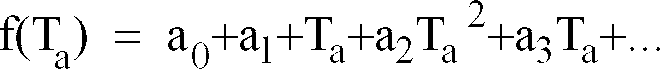
- A thermometer as defined in claim 25 wherein the signal Vir is approximated by using the formula:

- A thermometer as defined in any preceding claim in which said enabling means includes:a shutter carried by said housing and movable between a first position blocking transmission of said radiation from said directing means to said sensor and a second position which enables passage of said radiation to said sensor;means for moving said shutter between said first and second positions;and means for controlling movement of said shutter to enable response of said sensor to said radiation to exhibit said transient response upon receipt of said radiation.
- A thermometer as defined in claim 27 in which said controlling means enables movement of said shutter to said first position substantially upon termination of said transient response.
- A thermometer as defined in claim 27 or 28 in which said controlling means includes means for suppressing and absorbing noise and shock developed upon the movement of said shutter between said first and second positions.
- A thermometer as defined in claim 27 or 28 or 29 in which said housing includes an interior chamber in which said sensor is contained, and in which said shutter is mounted as to be in thermal equilibrium with said sensor.
- A thermometer as defined in any of claims 27 to 30 which includes means for supplying said electrical means with input signals indicative of the ambient temperature of the said sensor, and in which the actuation of said shutter enables the calculation of the temperature differential between said sensor and said object.
- A thermometer as defined in any of claims 27 to 31 in which said electrical means includes means for responding to actuation of said shutter in order to provide an indication signal that causes said transient response to be measured.
- A thermometer as defined in any of claims 27 to 32 in which said shutter exhibits a low thermal conductivity between a first surface which faces said directing means and a second surface which faces said sensor.
- A thermometer as defined in claim 33 in which both of said surfaces of said shutter are reflective to the said radiation.
- A method for measuring the temperature of an object with a thermometer having a housing providing an interior chamber and an ambient temperature sensor and a pyroelectric infrared sensor mounted within the chamber comprising the steps of:shielding said pyroelectric sensor from infrared radiation from exterior to the said thermometer housing;selectively exposing said pyroelectric sensor to infrared radiation substantially solely from the object to be measured to generate a first electrical signal which is a function of the temperature of the object to be measured and the ambient temperature of said pyroelectric sensor immediately prior to said selective exposing;sensing the ambient temperature of said pyroelectric sensor and generating a second electrical signal proportional thereto;generating an indicator signal upon said exposing of pyroelectric sensor;and in response to said indicator signal electrically processing said first and second electrical signals to calculate the temperature of the object to be measured.
- The method of claim 35 wherein the temperature of the object to be measured is calculated using the equation:


- The method of claim 36 wherein the signal Vir is approximated by using the formula:

- The method of any of claims 35 to 37 which comprises calibrating the sensitivity of said pyroelectric sensor prior to selectively exposing said pyroelectric sensor to infrared radiation from the object to be measured.
- The method of claim 38 wherein the said pyroelectric sensor is adapted to exhibit piezoelectric properties and calibrating the sensitivity of said pyroelectric sensor comprises:applying a predetermined calibration signal to said pyroelectric sensor so as to cause said pyroelectric sensor to generate a responsive electrical calibration signal;and correcting said first electrical signal generated by said pyroelectric sensor based upon said responsive electrical calibration signal and a predetermined standard value.
- The method of claim 39 wherein calibrating the sensitivity of said pyroelectric sensor comprises:applying a predetermined level of infrared radiation to said pyroelectric sensor so as to cause said pyroelectric sensor to generate a responsive electrical calibration signal;and correcting said first electrical signal generated by said pyroelectric sensor based upon said responsive electrical calibration signal and a predetermined standard value.
- An electronic thermometer comprising:a pyroelectric sensor (18) of a kind which exhibits only a transient response upon exposure to infrared radiation;a shutter (66) operable for exposing said pyroelectric sensor (18) to infrared radiation from an object (11) whose temperature is to be determined for a time period sufficient to permit said pyroelectric sensor (18) to provide said transient response;electrical circuit means (22) for processing the transient output produced by said pyroelectric sensor (18) in response to the single pulse of infrared radiation reaching the pyroelectric sensor (18) during the time period when said shutter (66) is open; andindicator means (78) connected to said electrical circuit means (22);said pyroelectric sensor (18) being contained within a housing (12) which carries said shutter (66) and an elongate wave guide (14) also being carried by said housing (12), said housing (12) shielding said pyroelectric sensor (18) from exterior infrared radiation other than that which is received through said wave guide (14) when said shutter (66) is open, and said wave guide (14) being interconnected with said pyroelectric sensor (18) so as to be in thermal equilibrium therewith and having an outer end (32) to receive infrared radiation from said object (11), an inner end (33) in operative alignment with said pyroelectric sensor (18) and a smooth and shiny interior surface (30) of low emissivity to facilitate transmission of infrared radiation from the object (11) to the pyroelectric sensor (18).
- A method for measuring the temperature of an object with a thermometer having a housing (12) providing an interior chamber (13) within which there is mounted an ambient temperature sensor (20) and a pyroelectric infrared sensor (18) which are shielded by said housing (12) from infrared radiation from exterior to the said thermometer housing (12), said method comprising:selectively exposing said pyroelectric sensor (18) to infrared radiation substantially solely from the object to be measured to generate a first electrical signal as a transient response which is a function of the temperature of the object to be measured and of the ambient temperature of said pyroelectric sensor;generating an enabling signal upon said exposing of said pyroelectric sensor (18);sensing the ambient temperature of said pyroelectric sensor (18) and generating a second electrical signal proportional thereto;and electrically processing said first and second electrical signals in response to said enabling signal to calculate the temperature of the object to be measured using the equation:
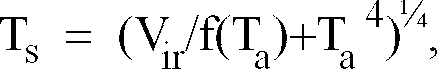
- An electronic thermometer comprising:a housing forming an interior chamber;a pyroelectric sensor means for sensing temperature change and generating a first electrical signal indicative thereof, said pyroelectric sensor means being mounted within said interior chamber;means for directing infrared radiation from the object to be measured to the pyroelectric sensor means, said directing means being mounted to said housing in operational alignment with said pyroelectric sensor means;shutter means for controlling the passing of infrared radiation from said directing means to said pyroelectric sensor means;temperature sensor means for sensing ambient temperature and generating a second electrical signal indicative thereof, said temperature sensor means being mounted within said chamber so as to sense the temperature of said pyroelectric sensor means;electrical circuit means for processing the first electrical signal generated by said pyroelectric sensor means indicative of temperature change and the second electrical signal generated by said temperature sensor means to calculate the temperature of the object to be measured, said circuit means being interconnected to said pyroelectric sensor means and said temperature sensor means; andindicator means for indicating the calculated temperature, said indicator means being connected to said circuit means.
- A process for measuring the temperature of an object with a thermometer having a housing providing an interior chamber and an ambient temperature sensor and a pyroelectric infrared sensor mounted within the chamber comprising the steps of:shielding the pyroelectric sensor from infrared radiation from exterior to the thermometer housing;selectively exposing the pyroelectric sensor to infrared radiation substantially solely from the object to be measured to generate a first electrical signal which is a function of the temperature of the object to be measured and the ambient temperature of the pyroelectric sensor immediately prior to said selective exposing;sensing the ambient temperature of the pyroelectric sensor and generating a second electrical signal proportional thereto; andelectrically processing said first and second electrical signals to calculate the temperature of the object to be measured.
- A heat differential detector comprising:a housing forming an interior chamber;means for directing infrared radiation from the surface of an object to the interior chamber, said directing means being mounted to said housing;a pyroelectric sensor means for sensing temperature change and generating an electrical signal indicative thereof, said sensor means comprising;a film of pyroelectric material having oppositely disposed forward and rearward surfaces;a first electrode mounted on said forward surface and a second electrode mounted on said rearward surface; andmeans for mounting said film within said interior chamber so the said forward surface is aligned to receive the infrared radiation from said directing means;electrical circuit means for comparing the electrical signal generated by said pyroelectric sensor means to a preselected value and generating an indicator control signal to drive an indicator means when the electrical signal generated by said pyroelectric sensor means exceeds said preselected value; andindicator means for indicating that the electrical signal generated by said pyroelectric sensor means exceeds said preselected value, said indicator means being connected to said electrical circuit means.
Applications Claiming Priority (3)
| Application Number | Priority Date | Filing Date | Title |
|---|---|---|---|
| US72433985A | 1985-04-17 | 1985-04-17 | |
| US724339 | 1985-04-17 | ||
| EP86902729A EP0219531B1 (en) | 1985-04-17 | 1986-04-15 | Infrared electronic thermometer and method for measuring temperature |
Related Parent Applications (2)
| Application Number | Title | Priority Date | Filing Date |
|---|---|---|---|
| EP86902729A Division EP0219531B1 (en) | 1985-04-17 | 1986-04-15 | Infrared electronic thermometer and method for measuring temperature |
| EP86902729.2 Division | 1986-10-29 |
Publications (3)
| Publication Number | Publication Date |
|---|---|
| EP0786649A2 true EP0786649A2 (en) | 1997-07-30 |
| EP0786649A3 EP0786649A3 (en) | 1997-08-20 |
| EP0786649B1 EP0786649B1 (en) | 2002-07-03 |
Family
ID=24910038
Family Applications (2)
| Application Number | Title | Priority Date | Filing Date |
|---|---|---|---|
| EP86902729A Expired - Lifetime EP0219531B1 (en) | 1985-04-17 | 1986-04-15 | Infrared electronic thermometer and method for measuring temperature |
| EP97201046A Expired - Lifetime EP0786649B1 (en) | 1985-04-17 | 1986-04-15 | Infrared electronic thermometer and method for measuring temperature |
Family Applications Before (1)
| Application Number | Title | Priority Date | Filing Date |
|---|---|---|---|
| EP86902729A Expired - Lifetime EP0219531B1 (en) | 1985-04-17 | 1986-04-15 | Infrared electronic thermometer and method for measuring temperature |
Country Status (6)
| Country | Link |
|---|---|
| US (1) | US4797840A (en) |
| EP (2) | EP0219531B1 (en) |
| JP (1) | JPH0663851B2 (en) |
| CA (2) | CA1265355A (en) |
| DE (4) | DE219531T1 (en) |
| WO (1) | WO1986006163A1 (en) |
Cited By (4)
| Publication number | Priority date | Publication date | Assignee | Title |
|---|---|---|---|---|
| EP0964231A2 (en) * | 1998-06-08 | 1999-12-15 | Advanced Monitors Corp. | Infrared thermometer |
| DE19926086C1 (en) * | 1999-06-08 | 2001-01-18 | Oriental System Technology Inc | Closure for clinical radiation thermometer has closure plate blocking waveguide channel fitted in base plate displaced via spring-loaded coupling element upon depression of operating element |
| EP1530034A1 (en) * | 2003-11-05 | 2005-05-11 | Microlife Intellectual Property GmbH | An infrared thermometer and a method for determining a temperature |
| US8657758B2 (en) | 2010-12-02 | 2014-02-25 | Welch Allyn, Inc. | Devices and methods for temperature determination |
Families Citing this family (184)
| Publication number | Priority date | Publication date | Assignee | Title |
|---|---|---|---|---|
| US5231595A (en) * | 1983-06-06 | 1993-07-27 | Minolta Camera Kabushiki Kaisha | Pyrometer |
| US5179936A (en) * | 1984-10-23 | 1993-01-19 | Intelligent Medical Systems, Inc. | Disposable speculum with membrane bonding ring |
| USRE34789E (en) * | 1985-04-17 | 1994-11-15 | Thermoscan Inc. | Infrared electronic thermometer and method for measuring temperature |
| DE3750278D1 (en) * | 1986-06-20 | 1994-09-01 | Lehmann Martin | Method for the contactless measurement of a temperature of a body and arrangement therefor. |
| US5001657A (en) * | 1986-06-24 | 1991-03-19 | Minolta Camera Kabushiki Kaisha | Radiation thermometer |
| US5007432A (en) * | 1987-04-27 | 1991-04-16 | Eltec Instruments, Inc. | Radiation detection method and apparatus |
| EP0411121A4 (en) * | 1987-12-25 | 1991-05-15 | Nippon Steel Corporation | Optical thermometer |
| JPH01202633A (en) * | 1988-02-08 | 1989-08-15 | Minolta Camera Co Ltd | Radiation thermometer |
| US4907895A (en) * | 1988-03-31 | 1990-03-13 | Ivac Corporation | Optical chopper for infrared thermometer |
| USRE34507E (en) * | 1988-04-12 | 1994-01-11 | Citizen Watch Co., Ltd. | Radiation clinical thermometer |
| US5232284A (en) * | 1988-04-12 | 1993-08-03 | Citizen Watch Co., Ltd. | Radiation clinical thermometer |
| JP2826337B2 (en) * | 1988-04-12 | 1998-11-18 | シチズン時計株式会社 | Radiation thermometer |
| US4895164A (en) * | 1988-09-15 | 1990-01-23 | Telatemp Corp. | Infrared clinical thermometer |
| US5018872A (en) * | 1988-11-01 | 1991-05-28 | Diatek, Inc. | Probe assembly for infrared thermometer |
| US4998826A (en) * | 1988-11-30 | 1991-03-12 | Telatemp Corporation | Agricultural infrared thermometer |
| US4993419A (en) * | 1988-12-06 | 1991-02-19 | Exergen Corporation | Radiation detector suitable for tympanic temperature measurement |
| US5445158A (en) * | 1988-12-06 | 1995-08-29 | Exergen Corporation | Radiation detector probe |
| US6219573B1 (en) | 1989-04-14 | 2001-04-17 | Exergen Corporation | Radiation detector probe |
| US5653238A (en) * | 1988-12-06 | 1997-08-05 | Exergen Corporation | Radiation detector probe |
| US5012813A (en) * | 1988-12-06 | 1991-05-07 | Exergen Corporation | Radiation detector having improved accuracy |
| US5199436A (en) * | 1988-12-06 | 1993-04-06 | Exergen Corporation | Radiation detector having improved accuracy |
| US5325863A (en) * | 1988-12-06 | 1994-07-05 | Exergen Corporation | Radiation detector with high thermal stability |
| US5381796A (en) * | 1992-05-22 | 1995-01-17 | Exergen Corporation | Ear thermometer radiation detector |
| US4977509A (en) * | 1988-12-09 | 1990-12-11 | Campsport, Inc. | Personal multi-purpose navigational apparatus and method for operation thereof |
| US5021980A (en) * | 1989-02-21 | 1991-06-04 | Lsi Logic Corporation | Remote measurement of temperature |
| US5056048A (en) * | 1989-07-18 | 1991-10-08 | Horst Seperant | Integrated digital standardized precision thermometer |
| US5163418A (en) * | 1989-09-19 | 1992-11-17 | Thermoscan Inc. | Speculum cover |
| US4993424A (en) * | 1989-12-04 | 1991-02-19 | Diatek, Incorporated | Infrared medical thermometer |
| DE69132890T2 (en) * | 1990-03-08 | 2002-08-29 | Alaris Medical Syst Inc | Thermally insulated probe |
| DE69120558T2 (en) * | 1990-03-12 | 1997-02-06 | Ivac Corp | System for temperature determination and calibration in a biomedical thermometer |
| US5150969A (en) * | 1990-03-12 | 1992-09-29 | Ivac Corporation | System and method for temperature determination and calibration in a biomedical probe |
| US5159936A (en) * | 1990-08-17 | 1992-11-03 | Mark Yelderman | Noncontact infrared tympanic thermometer |
| US5088834A (en) * | 1990-08-24 | 1992-02-18 | Thermoscan Inc. | Unitary probe cover |
| JPH0741026B2 (en) * | 1990-08-30 | 1995-05-10 | ヒロセ電機株式会社 | Thermometer |
| US5115815A (en) * | 1990-09-18 | 1992-05-26 | Hansen Donald H | Ophthermometry: a method of measuring eye temperature for diagnosis and surgery |
| US5165791A (en) * | 1990-09-18 | 1992-11-24 | Sumitomo Electric Industries, Ltd. | Method and apparatus for measuring temperature based on infrared light |
| WO1992010133A1 (en) * | 1990-12-12 | 1992-06-25 | Intelligent Medical Systems, Inc. | Infrared thermometer utilizing calibration mapping |
| US5469855A (en) * | 1991-03-08 | 1995-11-28 | Exergen Corporation | Continuous temperature monitor |
| US5127742A (en) * | 1991-04-19 | 1992-07-07 | Thermoscan Inc. | Apparatus and method for temperature measurement by radiation |
| US5178464A (en) * | 1991-04-19 | 1993-01-12 | Thermoscan Inc. | Balance infrared thermometer and method for measuring temperature |
| US5176130A (en) * | 1991-10-10 | 1993-01-05 | Interport International, Inc. | Infrared massage device |
| US5246292A (en) * | 1992-05-28 | 1993-09-21 | Eli Gal | Temperature measurement apparatus |
| JP3155625B2 (en) * | 1992-09-17 | 2001-04-16 | テルモ株式会社 | Thermometer |
| US5368038A (en) * | 1993-03-08 | 1994-11-29 | Thermoscan Inc. | Optical system for an infrared thermometer |
| JP3184659B2 (en) * | 1993-04-01 | 2001-07-09 | テルモ株式会社 | Thermometer |
| US5626147A (en) * | 1993-11-23 | 1997-05-06 | Thermoscan, Inc. | Tympanic thermometer |
| US5542764A (en) * | 1994-02-09 | 1996-08-06 | Test Projects, Inc. | Thermal difference detector system |
| US5813982A (en) * | 1994-02-22 | 1998-09-29 | Baratta; Francis I. | Noncontacting portable infrared intra-ocular pressure sensor |
| WO1995022928A1 (en) * | 1994-02-28 | 1995-08-31 | Economation, Inc. | Infrared tympanic thermometer |
| US5740809A (en) * | 1994-10-26 | 1998-04-21 | Baratta; Francis I. | Noninvasive infrared blood flow detector |
| US5725308A (en) * | 1994-12-23 | 1998-03-10 | Rtd Technology, Inc. | Quick registering thermometer |
| US5508546A (en) * | 1995-01-30 | 1996-04-16 | The United States Of America As Represented By The Adiministrator Of The National Aeronautics And Space Administration | Active pyroelectric infrared detector |
| US5673692A (en) * | 1995-02-03 | 1997-10-07 | Biosignals Ltd. Co. | Single site, multi-variable patient monitor |
| US5653537A (en) * | 1995-03-17 | 1997-08-05 | Ircon, Inc. | Non-contacting infrared temperature thermometer detector apparatus |
| AU709432B2 (en) | 1995-09-20 | 1999-08-26 | California Institute Of Technology | Detecting thermal discrepancies in vessel walls |
| US6615071B1 (en) | 1995-09-20 | 2003-09-02 | Board Of Regents, The University Of Texas System | Method and apparatus for detecting vulnerable atherosclerotic plaque |
| US6763261B2 (en) | 1995-09-20 | 2004-07-13 | Board Of Regents, The University Of Texas System | Method and apparatus for detecting vulnerable atherosclerotic plaque |
| WO1997024588A1 (en) * | 1995-12-28 | 1997-07-10 | Omron Corporation | Infrared thermometer |
| US5860741A (en) * | 1996-03-25 | 1999-01-19 | Oriental System Technology, Inc. | Absolute radiation thermometer |
| US5666956A (en) * | 1996-05-20 | 1997-09-16 | Buchert; Janusz Michal | Instrument and method for non-invasive monitoring of human tissue analyte by measuring the body's infrared radiation |
| US20020077564A1 (en) * | 1996-07-29 | 2002-06-20 | Farallon Medsystems, Inc. | Thermography catheter |
| US6689091B2 (en) * | 1996-08-02 | 2004-02-10 | Tuan Bui | Medical apparatus with remote control |
| US5895371A (en) * | 1996-08-27 | 1999-04-20 | Sabratek Corporation | Medical treatment apparatus and method |
| US5906636A (en) | 1996-09-20 | 1999-05-25 | Texas Heart Institute | Heat treatment of inflamed tissue |
| US7603166B2 (en) | 1996-09-20 | 2009-10-13 | Board Of Regents University Of Texas System | Method and apparatus for detection of vulnerable atherosclerotic plaque |
| TW314592B (en) * | 1996-09-25 | 1997-09-01 | Oriental System Technology Inc | The absolute radiation thermometer |
| US6179785B1 (en) | 1996-10-17 | 2001-01-30 | Sherwood Services, Ag | Ambient sensing feature for thermometer recalibration system |
| US6605057B2 (en) | 1996-10-24 | 2003-08-12 | Medtronic Ave, Inc. | Reinforced monorail balloon catheter |
| US5833367A (en) | 1996-11-12 | 1998-11-10 | Trutek, Inc. | Tympanic thermometer probe cover |
| US6030117A (en) | 1996-11-12 | 2000-02-29 | Trutek, Inc. | Tympanic thermometer probe cover |
| US5871449A (en) * | 1996-12-27 | 1999-02-16 | Brown; David Lloyd | Device and method for locating inflamed plaque in an artery |
| US5991652A (en) * | 1997-03-17 | 1999-11-23 | Thermoscan Inc. | Protective two position shell for an infrared thermometer |
| KR100301747B1 (en) * | 1997-03-26 | 2001-09-03 | 이마이 기요스케 | Pyroelectric infrared ray sensor |
| US5897505A (en) * | 1997-05-13 | 1999-04-27 | Feinberg; Barry I. | Selective tissue conductance/thermography sensor apparatus |
| US5823966A (en) * | 1997-05-20 | 1998-10-20 | Buchert; Janusz Michal | Non-invasive continuous blood glucose monitoring |
| WO1998055841A2 (en) | 1997-06-03 | 1998-12-10 | Trutek Inc. | Tympanic thermometer with modular sensing probe |
| US6056435A (en) * | 1997-06-24 | 2000-05-02 | Exergen Corporation | Ambient and perfusion normalized temperature detector |
| EP1304555B1 (en) * | 1997-07-16 | 2007-05-23 | Terumo Kabushiki Kaisha | Ear type clinical thermometer |
| US5812270A (en) * | 1997-09-17 | 1998-09-22 | Ircon, Inc. | Window contamination detector |
| DE19757447A1 (en) * | 1997-12-23 | 1999-07-01 | Braun Gmbh | Temperature calculation method for radiation thermometers |
| AU2316099A (en) | 1998-01-12 | 1999-07-26 | Mdi Instruments, Inc. | Ear examining device with temperature sensor |
| US5951486A (en) | 1998-10-23 | 1999-09-14 | Mdi Instruments, Inc. | Apparatus and method for analysis of ear pathologies using combinations of acoustic reflectance, temperature and chemical response |
| US5967992A (en) | 1998-06-03 | 1999-10-19 | Trutex, Inc. | Radiometric temperature measurement based on empirical measurements and linear functions |
| US6224256B1 (en) | 1998-06-18 | 2001-05-01 | Harry Bala | Cover for medical probe |
| US6090050A (en) * | 1998-07-16 | 2000-07-18 | Salix Medical, Inc. | Thermometric apparatus and method |
| US6292685B1 (en) * | 1998-09-11 | 2001-09-18 | Exergen Corporation | Temporal artery temperature detector |
| IL126224A0 (en) | 1998-09-15 | 1999-05-09 | Gerlitz Jonathan | Ear thermometer and detector therefor |
| US6398727B1 (en) * | 1998-12-23 | 2002-06-04 | Baxter International Inc. | Method and apparatus for providing patient care |
| US6231560B1 (en) * | 1999-02-10 | 2001-05-15 | Baxter International Inc | Method and apparatus for automatically controlling the level of medication |
| US6123454A (en) | 1999-06-11 | 2000-09-26 | Trutek, Inc. | Tympanic thermometer disposable probe cover with further stretching prevention structure |
| US7426409B2 (en) * | 1999-06-25 | 2008-09-16 | Board Of Regents, The University Of Texas System | Method and apparatus for detecting vulnerable atherosclerotic plaque |
| US6255622B1 (en) | 1999-10-27 | 2001-07-03 | Hewlett-Packard Company | Electronic device having external surface thermal feedback |
| US6694181B2 (en) | 2001-02-12 | 2004-02-17 | Scimed Life Systems, Inc. | Methods and devices for detecting vulnerable plaque |
| US6514214B2 (en) | 2001-02-13 | 2003-02-04 | Scimed Life Systems, Inc. | Intravascular temperature sensor |
| GB0104203D0 (en) | 2001-02-21 | 2001-04-11 | Secr Defence | Calibrating radiometers |
| US6631287B2 (en) * | 2001-04-03 | 2003-10-07 | Welch Allyn, Inc. | Infrared thermometer |
| CA2444490A1 (en) * | 2001-06-19 | 2002-12-27 | Welch Allyn, Inc. | Infrared thermometer |
| GB0115308D0 (en) * | 2001-06-22 | 2001-08-15 | Caretek Ltd | Medical diagnostic instrument |
| EP1397069A1 (en) * | 2001-06-22 | 2004-03-17 | Caretek Limited | Diagnostic temperature probe |
| US6637931B2 (en) * | 2001-07-19 | 2003-10-28 | Oriental System Technology Inc. | Probe for use in an infrared thermometer |
| US20030125662A1 (en) | 2002-01-03 | 2003-07-03 | Tuan Bui | Method and apparatus for providing medical treatment therapy based on calculated demand |
| US8303514B2 (en) * | 2002-01-25 | 2012-11-06 | Vital Accuracy Partners | Means and apparatus for rapid, accurate, non-contacting measurement of the core temperature of animals and humans |
| US7336987B2 (en) * | 2002-01-25 | 2008-02-26 | Laurence Laird W | Method and apparatus for rapid, non-contact measurement of the core temperature of animals and humans |
| US10173008B2 (en) | 2002-01-29 | 2019-01-08 | Baxter International Inc. | System and method for communicating with a dialysis machine through a network |
| US20030140928A1 (en) * | 2002-01-29 | 2003-07-31 | Tuan Bui | Medical treatment verification system and method |
| US8775196B2 (en) * | 2002-01-29 | 2014-07-08 | Baxter International Inc. | System and method for notification and escalation of medical data |
| US20040172301A1 (en) * | 2002-04-30 | 2004-09-02 | Mihai Dan M. | Remote multi-purpose user interface for a healthcare system |
| US8234128B2 (en) | 2002-04-30 | 2012-07-31 | Baxter International, Inc. | System and method for verifying medical device operational parameters |
| US20040176667A1 (en) * | 2002-04-30 | 2004-09-09 | Mihai Dan M. | Method and system for medical device connectivity |
| US20040172300A1 (en) * | 2002-04-30 | 2004-09-02 | Mihai Dan M. | Method and system for integrating data flows |
| US20040167804A1 (en) * | 2002-04-30 | 2004-08-26 | Simpson Thomas L.C. | Medical data communication notification and messaging system and method |
| US20050065817A1 (en) * | 2002-04-30 | 2005-03-24 | Mihai Dan M. | Separation of validated information and functions in a healthcare system |
| AU2003239375A1 (en) * | 2002-05-07 | 2003-11-11 | Volcano Therapeutics, Inc. | Systems and methods for detecting vulnerable plaque |
| DE60325891D1 (en) * | 2002-12-12 | 2009-03-05 | Covidien Ag | Spitze für thermisches trommelfellthermometer |
| US7434991B2 (en) * | 2002-12-12 | 2008-10-14 | Covidien Ag | Thermal tympanic thermometer |
| US6968222B2 (en) | 2003-05-02 | 2005-11-22 | Oculir, Inc. | Methods and device for non-invasive analyte measurement |
| US6975892B2 (en) * | 2003-10-21 | 2005-12-13 | Oculir, Inc. | Methods for non-invasive analyte measurement from the conjunctiva |
| US6958039B2 (en) * | 2003-05-02 | 2005-10-25 | Oculir, Inc. | Method and instruments for non-invasive analyte measurement |
| US20050043630A1 (en) * | 2003-08-21 | 2005-02-24 | Buchert Janusz Michal | Thermal Emission Non-Invasive Analyte Monitor |
| US7107088B2 (en) | 2003-08-25 | 2006-09-12 | Sarnoff Corporation | Pulse oximetry methods and apparatus for use within an auditory canal |
| EP1670353A4 (en) * | 2003-08-25 | 2009-03-11 | Sarnoff Corp | Monitoring using signals detected from auditory canal |
| US20060224057A1 (en) * | 2003-10-21 | 2006-10-05 | Oculir, Inc. | Methods for non-invasive analyte measurement |
| US20050207470A1 (en) * | 2004-01-26 | 2005-09-22 | Bennett Timothy J | Focusing thermometer |
| US20080009688A1 (en) * | 2004-04-14 | 2008-01-10 | Oculir, Inc. | Methods for non-invasive analyte measurement |
| US20060258919A1 (en) * | 2004-04-14 | 2006-11-16 | Oculir, Inc. | Non-Invasive Analyte Measurement Device for Measuring Tears and Other Ocular Elements Using Electromagnetic Radiation and Method of Using the Same |
| US20060047214A1 (en) * | 2004-08-24 | 2006-03-02 | Jacob Fraden | Wireless medical probe |
| US7507019B2 (en) * | 2006-05-19 | 2009-03-24 | Covidien Ag | Thermometer calibration |
| US20070268954A1 (en) * | 2006-05-19 | 2007-11-22 | Sherwood Services Ag | Portable test apparatus for radiation-sensing thermometer |
| US20070268952A1 (en) * | 2006-05-19 | 2007-11-22 | Sherwood Services Ag | Thermometer calibration by immersion in non-electrically conductive liquid |
| US7549792B2 (en) | 2006-10-06 | 2009-06-23 | Covidien Ag | Electronic thermometer with selectable modes |
| TW200841859A (en) * | 2007-04-27 | 2008-11-01 | Actherm Inc | Infrared thermometer |
| US20090076441A1 (en) * | 2007-08-15 | 2009-03-19 | Eric Sebban | Aspirator assembly |
| US8100886B2 (en) * | 2007-08-15 | 2012-01-24 | Visiomed Group Sa | Aspirator assembly |
| US20090125330A1 (en) * | 2007-11-09 | 2009-05-14 | Eric Sebban | Non-invasive medical data collecting assembly |
| EP2250720B1 (en) * | 2008-03-07 | 2019-08-14 | Milwaukee Electric Tool Corporation | Battery pack for use with a power tool and a non-motorized sensing tool |
| US20090257469A1 (en) * | 2008-04-09 | 2009-10-15 | Jones Mike N | Infrared thermometer |
| US10089443B2 (en) | 2012-05-15 | 2018-10-02 | Baxter International Inc. | Home medical device systems and methods for therapy prescription and tracking, servicing and inventory |
| US8057679B2 (en) | 2008-07-09 | 2011-11-15 | Baxter International Inc. | Dialysis system having trending and alert generation |
| US8554579B2 (en) | 2008-10-13 | 2013-10-08 | Fht, Inc. | Management, reporting and benchmarking of medication preparation |
| CA2762188C (en) * | 2008-10-23 | 2017-01-03 | Kaz Europe Sa | Non-contact medical thermometer with stray radiation shielding |
| US8317720B2 (en) * | 2008-12-24 | 2012-11-27 | Herdx, Inc. | Core-temperature based herd management system and method |
| CA2748724C (en) | 2008-12-30 | 2018-01-02 | Zoner Llc | Automatically balancing register for hvac systems |
| US8245877B2 (en) | 2009-07-22 | 2012-08-21 | Gotohti.Com Inc. | Dispenser with palm reader |
| US20110194585A1 (en) * | 2010-02-09 | 2011-08-11 | Abhishek Shrivastava | Multiple object non-contact thermometer |
| US20110228810A1 (en) * | 2010-02-09 | 2011-09-22 | O'hara Gary | Multiple object talking non-contact thermometer |
| JP5090483B2 (en) | 2010-02-18 | 2012-12-05 | 粟井 志壽子 | Temperature measuring mirror and mirror structure |
| US20120083710A1 (en) | 2010-09-30 | 2012-04-05 | Medism Ltd. | Ergonomic hand-held thermometer |
| CN103813812B (en) | 2011-02-23 | 2016-08-10 | 新星湾药物有限公司 | There are the contact lens cleaning systems of monitor |
| DE102011103818A1 (en) | 2011-06-01 | 2012-12-06 | Meas Deutschland Gmbh | Infrared sensor arrangement and its use |
| WO2013060859A1 (en) * | 2011-10-28 | 2013-05-02 | Vlaamse Instelling Voor Technologisch Onderzoek Nv (Vito Nv) | Infrared presence detector for detecting a presence of an object in a surveillance area |
| US9606003B2 (en) * | 2012-03-28 | 2017-03-28 | Yonatan Gerlitz | Clinical hand-held infrared thermometer with special optical configuration |
| JP2013221796A (en) * | 2012-04-13 | 2013-10-28 | Yazaki Corp | Shunt resistor based current sensor |
| US9307912B2 (en) | 2012-08-08 | 2016-04-12 | Welch Allyn, Inc. | Temperature measurement system |
| SG11201501427PA (en) | 2012-08-31 | 2015-03-30 | Baxter Corp Englewood | Medication requisition fulfillment system and method |
| US8452382B1 (en) * | 2012-09-21 | 2013-05-28 | Brooklands Inc. | Non-contact thermometer sensing a carotid artery |
| CA2889210C (en) | 2012-10-26 | 2020-12-15 | Baxter Corporation Englewood | Improved image acquisition for medical dose preparation system |
| NZ707430A (en) | 2012-10-26 | 2016-04-29 | Baxter Corp Englewood | Improved work station for medical dose preparation system |
| WO2014087253A2 (en) | 2012-11-19 | 2014-06-12 | Kaz Europe Sa | Medical thermometer having an improved optics system |
| JP6401175B2 (en) | 2012-11-19 | 2018-10-03 | カズ ヨーロッパ エス・アー・エール・エル | Non-contact medical thermometer with distance sensing and compensation |
| US9625744B2 (en) | 2013-10-31 | 2017-04-18 | Novabay Pharmaceuticals, Inc. | Contact lens cleaning system with insulation |
| CN104068832A (en) * | 2014-06-20 | 2014-10-01 | 京东方科技集团股份有限公司 | Body surface thermometer and wearable display device |
| WO2016003902A1 (en) | 2014-06-30 | 2016-01-07 | Baxter Corporation Englewood | Managed medical information exchange |
| GB2528044B (en) | 2014-07-04 | 2018-08-22 | Arc Devices Ni Ltd | Non-touch optical detection of vital signs |
| CN104155008A (en) * | 2014-07-28 | 2014-11-19 | 上海电力学院 | Method for correcting measuring errors of infrared temperature monitoring system |
| US11575673B2 (en) | 2014-09-30 | 2023-02-07 | Baxter Corporation Englewood | Central user management in a distributed healthcare information management system |
| US11107574B2 (en) | 2014-09-30 | 2021-08-31 | Baxter Corporation Englewood | Management of medication preparation with formulary management |
| US9854973B2 (en) | 2014-10-25 | 2018-01-02 | ARC Devices, Ltd | Hand-held medical-data capture-device interoperation with electronic medical record systems |
| JP2017535875A (en) | 2014-11-13 | 2017-11-30 | シーメンス アクチエンゲゼルシヤフトSiemens Aktiengesellschaft | Product production planning method and production module with self-describing information |
| AU2015358483A1 (en) | 2014-12-05 | 2017-06-15 | Baxter Corporation Englewood | Dose preparation data analytics |
| CA2978455A1 (en) | 2015-03-03 | 2016-09-09 | Baxter Corporation Englewood | Pharmacy workflow management with integrated alerts |
| JP2016217937A (en) * | 2015-05-22 | 2016-12-22 | 日本セラミック株式会社 | Pyroelectric infrared human body detection device |
| CA2985719C (en) | 2015-06-25 | 2024-03-26 | Gambro Lundia Ab | Medical device system and method having a distributed database |
| US11874173B1 (en) | 2015-11-24 | 2024-01-16 | Exergen Corporation | Devices and methods for detecting inflammation |
| US20190310136A1 (en) * | 2016-10-25 | 2019-10-10 | Nokia Technologies Oy | Thermometer and associated method, apparatus and computer program product |
| AU2017381172A1 (en) | 2016-12-21 | 2019-06-13 | Gambro Lundia Ab | Medical device system including information technology infrastructure having secure cluster domain supporting external domain |
| US10506926B2 (en) | 2017-02-18 | 2019-12-17 | Arc Devices Limited | Multi-vital sign detector in an electronic medical records system |
| US10492684B2 (en) | 2017-02-21 | 2019-12-03 | Arc Devices Limited | Multi-vital-sign smartphone system in an electronic medical records system |
| US10909835B1 (en) | 2020-08-14 | 2021-02-02 | Temperature Gate Ip Holdings Llc | Rapid thermal dynamic image capture devices |
| US11164441B2 (en) | 2017-06-12 | 2021-11-02 | Temperature Gate Ip Holdings Llc | Rapid thermal dynamic image capture devices with increased recognition and monitoring capacity |
| US10602987B2 (en) | 2017-08-10 | 2020-03-31 | Arc Devices Limited | Multi-vital-sign smartphone system in an electronic medical records system |
| US10485431B1 (en) | 2018-05-21 | 2019-11-26 | ARC Devices Ltd. | Glucose multi-vital-sign system in an electronic medical records system |
| USD1015533S1 (en) | 2019-11-07 | 2024-02-20 | 623 Medical, Llc | Vapocoolant device |
| WO2021247300A1 (en) | 2020-06-01 | 2021-12-09 | Arc Devices Limited | Apparatus and methods for measuring blood pressure and other vital signs via a finger |
| CN111795748B (en) * | 2020-06-28 | 2021-10-19 | 芯海科技(深圳)股份有限公司 | Temperature measurement method, temperature measurement control device, temperature measurement equipment and storage medium |
Citations (7)
| Publication number | Priority date | Publication date | Assignee | Title |
|---|---|---|---|---|
| US3115030A (en) * | 1961-12-04 | 1963-12-24 | Barnes Eng Co | Calibration system |
| US3586439A (en) * | 1968-07-15 | 1971-06-22 | Kettering Scient Research Inc | Direct reading pyrometer employing pyroelectric crystal detector |
| US3777568A (en) * | 1971-12-21 | 1973-12-11 | Sensors Inc | D. c. electronic apparatus for ir radiation temperature measurement |
| US4005605A (en) * | 1974-07-22 | 1977-02-01 | Mikron Instrument Company, Inc. | Remote reading infrared thermometer |
| JPS5347884A (en) * | 1976-10-12 | 1978-04-28 | Matsushita Electric Ind Co Ltd | Infrared radiation thermometer |
| JPS5735740A (en) * | 1980-08-14 | 1982-02-26 | Matsushita Electric Ind Co Ltd | Temperature measuring device equipped with pyroelectric infrared sensor |
| GB2119925A (en) * | 1982-03-04 | 1983-11-23 | Mikron Instr | Transducer-transmitter for non-contact temperature |
Family Cites Families (9)
| Publication number | Priority date | Publication date | Assignee | Title |
|---|---|---|---|---|
| US3023398A (en) * | 1958-04-09 | 1962-02-27 | Charles L Siegert | Infra-red radiation monitor |
| US3549960A (en) * | 1967-12-20 | 1970-12-22 | Massachusetts Inst Technology | Thermo-photovoltaic converter having back-surface junctions |
| US3809920A (en) * | 1972-08-25 | 1974-05-07 | Us Navy | Polymeric pyroelectric detector |
| US4001586A (en) * | 1975-05-09 | 1977-01-04 | Plessey Incorporated | Thick film sensor and infrared detector |
| US4147562A (en) * | 1977-07-05 | 1979-04-03 | Honeywell Inc. | Pyroelectric detector |
| GB2071316B (en) * | 1979-09-12 | 1983-11-09 | Raytek Inc | Hand-held digital temperature measuring instrument |
| JPS5711634A (en) * | 1980-06-26 | 1982-01-21 | Tokyo Shibaura Electric Co | Apparatus for measuring live body information |
| US4379971A (en) * | 1980-11-10 | 1983-04-12 | Statitrol, Inc. | Pyroelectric sensor |
| US4423408A (en) * | 1981-02-09 | 1983-12-27 | Honeywell Inc. | Remote data gathering panel |
-
1986
- 1986-04-15 WO PCT/US1986/000782 patent/WO1986006163A1/en active IP Right Grant
- 1986-04-15 EP EP86902729A patent/EP0219531B1/en not_active Expired - Lifetime
- 1986-04-15 JP JP61502393A patent/JPH0663851B2/en not_active Expired - Fee Related
- 1986-04-15 DE DE198686902729T patent/DE219531T1/en active Pending
- 1986-04-15 EP EP97201046A patent/EP0786649B1/en not_active Expired - Lifetime
- 1986-04-15 DE DE3650770T patent/DE3650770T2/en not_active Expired - Fee Related
- 1986-04-15 DE DE3650723T patent/DE3650723T2/en not_active Expired - Fee Related
- 1986-04-15 US US07/009,181 patent/US4797840A/en not_active Ceased
- 1986-04-15 DE DE0786649T patent/DE786649T1/en active Pending
- 1986-04-17 CA CA000506939A patent/CA1265355A/en not_active Expired - Lifetime
-
1991
- 1991-10-28 CA CA91616213A patent/CA1314407E/en not_active Expired - Fee Related
Patent Citations (7)
| Publication number | Priority date | Publication date | Assignee | Title |
|---|---|---|---|---|
| US3115030A (en) * | 1961-12-04 | 1963-12-24 | Barnes Eng Co | Calibration system |
| US3586439A (en) * | 1968-07-15 | 1971-06-22 | Kettering Scient Research Inc | Direct reading pyrometer employing pyroelectric crystal detector |
| US3777568A (en) * | 1971-12-21 | 1973-12-11 | Sensors Inc | D. c. electronic apparatus for ir radiation temperature measurement |
| US4005605A (en) * | 1974-07-22 | 1977-02-01 | Mikron Instrument Company, Inc. | Remote reading infrared thermometer |
| JPS5347884A (en) * | 1976-10-12 | 1978-04-28 | Matsushita Electric Ind Co Ltd | Infrared radiation thermometer |
| JPS5735740A (en) * | 1980-08-14 | 1982-02-26 | Matsushita Electric Ind Co Ltd | Temperature measuring device equipped with pyroelectric infrared sensor |
| GB2119925A (en) * | 1982-03-04 | 1983-11-23 | Mikron Instr | Transducer-transmitter for non-contact temperature |
Non-Patent Citations (1)
| Title |
|---|
| PATENT ABSTRACTS OF JAPAN vol. 002, no. 084 (E-042), 8 July 1978 & JP 53 047884 A (MATSUSHITA ELECTRIC IND CO LTD), 28 April 1978, * |
Cited By (6)
| Publication number | Priority date | Publication date | Assignee | Title |
|---|---|---|---|---|
| EP0964231A2 (en) * | 1998-06-08 | 1999-12-15 | Advanced Monitors Corp. | Infrared thermometer |
| EP0964231A3 (en) * | 1998-06-08 | 2000-03-01 | Advanced Monitors Corp. | Infrared thermometer |
| DE19926086C1 (en) * | 1999-06-08 | 2001-01-18 | Oriental System Technology Inc | Closure for clinical radiation thermometer has closure plate blocking waveguide channel fitted in base plate displaced via spring-loaded coupling element upon depression of operating element |
| EP1530034A1 (en) * | 2003-11-05 | 2005-05-11 | Microlife Intellectual Property GmbH | An infrared thermometer and a method for determining a temperature |
| WO2005050153A1 (en) * | 2003-11-05 | 2005-06-02 | Microlife Intellectual Property Gmbh | An infrared thermometer and a method for determining a temperature |
| US8657758B2 (en) | 2010-12-02 | 2014-02-25 | Welch Allyn, Inc. | Devices and methods for temperature determination |
Also Published As
| Publication number | Publication date |
|---|---|
| AU587090B2 (en) | 1989-08-03 |
| EP0219531B1 (en) | 1999-07-14 |
| EP0219531A4 (en) | 1989-05-26 |
| CA1265355A (en) | 1990-02-06 |
| EP0219531A1 (en) | 1987-04-29 |
| JPH0663851B2 (en) | 1994-08-22 |
| DE219531T1 (en) | 1987-08-13 |
| EP0786649B1 (en) | 2002-07-03 |
| CA1314407E (en) | 1993-03-16 |
| US4797840A (en) | 1989-01-10 |
| DE3650723D1 (en) | 1999-08-19 |
| DE3650723T2 (en) | 2000-03-16 |
| DE3650770D1 (en) | 2002-08-08 |
| DE3650770T2 (en) | 2003-02-27 |
| JPS62503119A (en) | 1987-12-10 |
| DE786649T1 (en) | 1998-05-14 |
| AU6602186A (en) | 1988-06-02 |
| WO1986006163A1 (en) | 1986-10-23 |
| EP0786649A3 (en) | 1997-08-20 |
Similar Documents
| Publication | Publication Date | Title |
|---|---|---|
| US4797840A (en) | Infrared electronic thermometer and method for measuring temperature | |
| USRE34789E (en) | Infrared electronic thermometer and method for measuring temperature | |
| US6047205A (en) | Radiation detector probe | |
| US6219573B1 (en) | Radiation detector probe | |
| US5445158A (en) | Radiation detector probe | |
| US5012813A (en) | Radiation detector having improved accuracy | |
| US4900162A (en) | Infrared thermometry system and method | |
| CA2098313C (en) | Infrared thermometer utilizing calibration mapping | |
| US4854730A (en) | Radiation thermometer and method for measuring temperature | |
| US5325863A (en) | Radiation detector with high thermal stability | |
| US6241384B1 (en) | Axillary infrared thermometer and method of use | |
| US5017018A (en) | Clinical thermometer | |
| US4932789A (en) | Radiation clinical thermometer | |
| EP0667751B1 (en) | Noncontact infrared tympanic thermometer | |
| US5860741A (en) | Absolute radiation thermometer | |
| JPH0617826B2 (en) | Pyrometer | |
| EP0572095B1 (en) | Temperature measurement apparatus | |
| US20020186745A1 (en) | Axillary infrared thermometer and method of use | |
| JP3885323B2 (en) | Radiation thermometer | |
| EP0588643A1 (en) | Thermal image detecting apparatus | |
| JP3855407B2 (en) | Radiation thermometer | |
| EP0968405A1 (en) | An application specific integrated circuit for use with an ir thermometer |
Legal Events
| Date | Code | Title | Description |
|---|---|---|---|
| PUAI | Public reference made under article 153(3) epc to a published international application that has entered the european phase |
Free format text: ORIGINAL CODE: 0009012 |
|
| PUAL | Search report despatched |
Free format text: ORIGINAL CODE: 0009013 |
|
| 17P | Request for examination filed |
Effective date: 19970506 |
|
| AC | Divisional application: reference to earlier application |
Ref document number: 219531 Country of ref document: EP |
|
| AK | Designated contracting states |
Kind code of ref document: A2 Designated state(s): BE CH DE FR GB IT LI LU NL SE |
|
| AK | Designated contracting states |
Kind code of ref document: A3 Designated state(s): BE CH DE FR GB IT LI LU NL SE |
|
| ITCL | It: translation for ep claims filed |
Representative=s name: STUDIO TORTA SOCIETA' SEMPLICE |
|
| EL | Fr: translation of claims filed | ||
| TCNL | Nl: translation of patent claims filed | ||
| RAP1 | Party data changed (applicant data changed or rights of an application transferred) |
Owner name: THERMOSCAN INC. |
|
| 17Q | First examination report despatched |
Effective date: 19980127 |
|
| DET | De: translation of patent claims | ||
| GRAG | Despatch of communication of intention to grant |
Free format text: ORIGINAL CODE: EPIDOS AGRA |
|
| GRAG | Despatch of communication of intention to grant |
Free format text: ORIGINAL CODE: EPIDOS AGRA |
|
| GRAH | Despatch of communication of intention to grant a patent |
Free format text: ORIGINAL CODE: EPIDOS IGRA |
|
| GRAH | Despatch of communication of intention to grant a patent |
Free format text: ORIGINAL CODE: EPIDOS IGRA |
|
| GRAA | (expected) grant |
Free format text: ORIGINAL CODE: 0009210 |
|
| AC | Divisional application: reference to earlier application |
Ref document number: 219531 Country of ref document: EP |
|
| AK | Designated contracting states |
Kind code of ref document: B1 Designated state(s): BE CH DE FR GB IT LI LU NL SE |
|
| PG25 | Lapsed in a contracting state [announced via postgrant information from national office to epo] |
Ref country code: LI Free format text: LAPSE BECAUSE OF FAILURE TO SUBMIT A TRANSLATION OF THE DESCRIPTION OR TO PAY THE FEE WITHIN THE PRESCRIBED TIME-LIMIT Effective date: 20020703 Ref country code: IT Free format text: LAPSE BECAUSE OF FAILURE TO SUBMIT A TRANSLATION OF THE DESCRIPTION OR TO PAY THE FEE WITHIN THE PRESCRIBED TIME-LIMIT;WARNING: LAPSES OF ITALIAN PATENTS WITH EFFECTIVE DATE BEFORE 2007 MAY HAVE OCCURRED AT ANY TIME BEFORE 2007. THE CORRECT EFFECTIVE DATE MAY BE DIFFERENT FROM THE ONE RECORDED. Effective date: 20020703 Ref country code: CH Free format text: LAPSE BECAUSE OF FAILURE TO SUBMIT A TRANSLATION OF THE DESCRIPTION OR TO PAY THE FEE WITHIN THE PRESCRIBED TIME-LIMIT Effective date: 20020703 Ref country code: BE Free format text: LAPSE BECAUSE OF FAILURE TO SUBMIT A TRANSLATION OF THE DESCRIPTION OR TO PAY THE FEE WITHIN THE PRESCRIBED TIME-LIMIT Effective date: 20020703 |
|
| REG | Reference to a national code |
Ref country code: CH Ref legal event code: EP |
|
| REG | Reference to a national code |
Ref country code: CH Ref legal event code: NV Representative=s name: KIRKER & CIE SA |
|
| REF | Corresponds to: |
Ref document number: 3650770 Country of ref document: DE Date of ref document: 20020808 |
|
| PG25 | Lapsed in a contracting state [announced via postgrant information from national office to epo] |
Ref country code: SE Free format text: LAPSE BECAUSE OF FAILURE TO SUBMIT A TRANSLATION OF THE DESCRIPTION OR TO PAY THE FEE WITHIN THE PRESCRIBED TIME-LIMIT Effective date: 20021003 |
|
| ET | Fr: translation filed | ||
| REG | Reference to a national code |
Ref country code: CH Ref legal event code: PL |
|
| PGFP | Annual fee paid to national office [announced via postgrant information from national office to epo] |
Ref country code: GB Payment date: 20030325 Year of fee payment: 18 |
|
| PGFP | Annual fee paid to national office [announced via postgrant information from national office to epo] |
Ref country code: DE Payment date: 20030326 Year of fee payment: 18 |
|
| PG25 | Lapsed in a contracting state [announced via postgrant information from national office to epo] |
Ref country code: LU Free format text: LAPSE BECAUSE OF NON-PAYMENT OF DUE FEES Effective date: 20030415 |
|
| PGFP | Annual fee paid to national office [announced via postgrant information from national office to epo] |
Ref country code: NL Payment date: 20030417 Year of fee payment: 18 Ref country code: FR Payment date: 20030417 Year of fee payment: 18 |
|
| PLBE | No opposition filed within time limit |
Free format text: ORIGINAL CODE: 0009261 |
|
| STAA | Information on the status of an ep patent application or granted ep patent |
Free format text: STATUS: NO OPPOSITION FILED WITHIN TIME LIMIT |
|
| 26N | No opposition filed |
Effective date: 20030404 |
|
| PG25 | Lapsed in a contracting state [announced via postgrant information from national office to epo] |
Ref country code: GB Free format text: LAPSE BECAUSE OF NON-PAYMENT OF DUE FEES Effective date: 20040415 |
|
| PG25 | Lapsed in a contracting state [announced via postgrant information from national office to epo] |
Ref country code: NL Free format text: LAPSE BECAUSE OF NON-PAYMENT OF DUE FEES Effective date: 20041101 |
|
| PG25 | Lapsed in a contracting state [announced via postgrant information from national office to epo] |
Ref country code: DE Free format text: LAPSE BECAUSE OF NON-PAYMENT OF DUE FEES Effective date: 20041103 |
|
| GBPC | Gb: european patent ceased through non-payment of renewal fee |
Effective date: 20040415 |
|
| PG25 | Lapsed in a contracting state [announced via postgrant information from national office to epo] |
Ref country code: FR Free format text: LAPSE BECAUSE OF NON-PAYMENT OF DUE FEES Effective date: 20041231 |
|
| NLV4 | Nl: lapsed or anulled due to non-payment of the annual fee |
Effective date: 20041101 |
|
| REG | Reference to a national code |
Ref country code: FR Ref legal event code: ST |