EP0780064B1 - Hydrodynamic shoe-pad and shoe provided therewith - Google Patents
Hydrodynamic shoe-pad and shoe provided therewith Download PDFInfo
- Publication number
- EP0780064B1 EP0780064B1 EP96120680A EP96120680A EP0780064B1 EP 0780064 B1 EP0780064 B1 EP 0780064B1 EP 96120680 A EP96120680 A EP 96120680A EP 96120680 A EP96120680 A EP 96120680A EP 0780064 B1 EP0780064 B1 EP 0780064B1
- Authority
- EP
- European Patent Office
- Prior art keywords
- bladder
- fluid
- inner bladder
- heel
- hydrodynamic pad
- Prior art date
- Legal status (The legal status is an assumption and is not a legal conclusion. Google has not performed a legal analysis and makes no representation as to the accuracy of the status listed.)
- Expired - Lifetime
Links
Images

Classifications
-
- A—HUMAN NECESSITIES
- A43—FOOTWEAR
- A43B—CHARACTERISTIC FEATURES OF FOOTWEAR; PARTS OF FOOTWEAR
- A43B17/00—Insoles for insertion, e.g. footbeds or inlays, for attachment to the shoe after the upper has been joined
- A43B17/02—Insoles for insertion, e.g. footbeds or inlays, for attachment to the shoe after the upper has been joined wedge-like or resilient
- A43B17/03—Insoles for insertion, e.g. footbeds or inlays, for attachment to the shoe after the upper has been joined wedge-like or resilient filled with a gas, e.g. air
-
- A—HUMAN NECESSITIES
- A43—FOOTWEAR
- A43B—CHARACTERISTIC FEATURES OF FOOTWEAR; PARTS OF FOOTWEAR
- A43B13/00—Soles; Sole-and-heel integral units
- A43B13/14—Soles; Sole-and-heel integral units characterised by the constructive form
- A43B13/18—Resilient soles
- A43B13/189—Resilient soles filled with a non-compressible fluid, e.g. gel, water
-
- A—HUMAN NECESSITIES
- A43—FOOTWEAR
- A43B—CHARACTERISTIC FEATURES OF FOOTWEAR; PARTS OF FOOTWEAR
- A43B13/00—Soles; Sole-and-heel integral units
- A43B13/14—Soles; Sole-and-heel integral units characterised by the constructive form
- A43B13/18—Resilient soles
- A43B13/20—Pneumatic soles filled with a compressible fluid, e.g. air, gas
- A43B13/206—Pneumatic soles filled with a compressible fluid, e.g. air, gas provided with tubes or pipes or tubular shaped cushioning members
Definitions
- the present invention relates to shoes and components thereof, and more particularly to stabilizing and cushioning systems for shoes.
- ground reaction forces associated with foot strike while walking are typically between one and one-and-one-half an individual's body weight.
- Runners impact the ground with vertical forces as high as three to four times their body weight, depending upon their speed.
- impact forces as high as five to six times an athlete's body weight have been recorded.
- the heel strike phase begins with the initial contact at the lateral or outer portion of the heel, and lasts until the rest of the foot or shoe contacts the ground, known as the flat foot phase.
- the flat foot phase lasts until the runner's heel lifts, thereby beginning the toe off phase.
- the runner's foot typically pronates or supinates, and such pronation or supination will result in lateral movement of the runner's heel if the heel is not adequately stabilized.
- the typical running shoe attempts to stabilize the runner's heel by providing a generally rigid heel cup that is shaped to snugly receive the runner's heel.
- the heel cups are padded for comfort, and the padding is compressible. Accordingly, the runner's heel experiences a degree of lateral movement relative to the heel cup as the heel is moved against the padding and the padding is compressed.
- the ground reaction forces experienced as the runner's foot is in contact with the ground are partially attenuated through a complex natural three-dimensional motion of the foot at the subtalar, metatarsal, other joint areas, and the calcaneous bone. Those areas of focused impact are generally concentrated in the heel and metatarsal regions of the foot. Accordingly, it is desirable to dissipate the impact forces and to limit joint motion beyond the natural motion of the foot.
- EVA and PU are lightweight and stable foam materials which possess viscous and elastic qualities.
- the density or durometer, i.e., hardness, of EVA and PU can be altered by adjusting the manufacturing technique to provide differing degrees of cushioning.
- Viscoelastic foam midsoles suffer a breakdown of their resiliency, or elasticity, when subjected to the repetitive compression resulting from foot impact. Thus, the cushioning provided by the "spring" of such viscoelastic midsoles is diminished or depleted over time by the repeated compression of wear.
- Recent commercial embodiments of shoes for cushioning impact include the use of a gel in the shoe soles by one manufacturer, and of a pressurized air bladder in the shoe soles by another manufacturer. Although devices do effect certain impact cushioning, tests show that the impact absorption of such devices still exhibits sharp peak impact loads considered undesirably high, particularly during sustained activity. Moreover, these commercial embodiments have the materials encapsulated under pressure and confined to a finite space; this encapsulation under pressure does not sufficiently accommodate different impact forces from persons of different weight or running at different speeds.
- Athletic shoes have been designed to accommodate impact loads of faster gaits while maintaining a sufficient combination of stiffness and cushioning to comfortably accommodate impact loads during a slow gait.
- the athletic shoes utilise fluid-filled bladders wherein the controlled flow of fluid between a rearward and forward chamber, as discussed in U.S. Patent Nos. 4,934,072 and 5,097,607, provides a cushioning system which dissipates impact loads in accordance to an individual runner's weight and gait.
- a self-reinitializing padding device having at least two fluid connected chambers which contain flowable material for use in applications in which it is desirable to initialize the padding device for subsequent use in absorbing and/ or distributing impact force, is known from WO 92/03070.
- One application for which the padding device is particularly well suited is as a foot padding device in footwear.
- the impact force of the user's foot deforms a primary chamber, thereby forcing some of the flowable material contained therein to flow into plurality of secondary chambers.
- the rate of the formation of the primary chamber exceeds the flow rate into the secondary chamber, thereby providing a cushioning effect.
- the portion of the footwear coinciding with the primary chamber loses contact with the ground, the force is removed from the primary chamber, thereby allowing the secondary chamber to contract and force some of the flowable material contained therein back into the primary chamber to reinitialize the padding device.
- the present invention provides a hydrodynamic pad for a shoe which stabilises and cushions the foot of a wearer, thereby advantageously addressing problems associated with prior art cushioning constructs.
- the hydrodynamic pad of a preferred embodiment of the present invention achieves this stabilising and cushioning by displacement of fluid between an inner bladder and an outer bladder.
- the inner bladder is adapted to be located in a shoe midsole at the center of pressure distribution generated by the compression generated during heel strike.
- the outer bladder is configured to coincide with the bottom periphery of the heel of the wearer, and the displacement of the fluid to the outer bladder causes the outer bladder to expand, thereby seating and stabilizing the wearer's heel during heel strike.
- the fluid displacement and the seating of the heel on the hydrodynamic pad maximizes cushioning and support of the wearer's heel.
- the hydrodynamic pad of a preferred embodiment is for insertion in the midsole of a shoe.
- the hydrodynamic pad includes an inner bladder having an anterior portion, a posterior portion, and two longitudinal side portions extending between the anterior and posterior portions.
- the outer bladder is positioned outwardly from at least the longitudinal side portions and the posterior portion of the inner bladder.
- Fluid channels extend between the inner bladder and the outer bladder so as to provide a fluid pathway therebetween, such that the fluid is movable between the inner and outer bladders.
- the outer bladder is a resilient bladder, and the expanded outer bladder is capable of forcing at least a portion of the fluid to return to the inner bladder when at least a portion of the compressive force is removed from the inner bladder.
- the outer bladder forces the fluid through the fluid channels such that the displaced fluid returns to the inner bladder and the outer bladder returns to an initial position.
- a single, continuous outer bladder is spaced away from the anterior portion, longitudinal side portions and posterior portion of the inner bladder, and the inner and outer bladders are connected by the fluid channels.
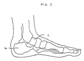
- Figure 1 is a schematic side view of the bones of a wearer's foot.
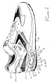
- Figure 2 is a partially cut-away, bottom isometric view of a shoe with a hydrodynamic pad in accordance with a preferred embodiment of the present invention.
- Figure 3 is a plan view of the hydrodynamic pad of Figure 2.
- Figure 4 is a cross-sectional view of the hydrodynamic pad of Figure 3 taken substantially along line 4-4 of Figure 3 showing the outer bladder in an initial position.
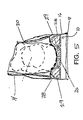
- Figure 5 is a cross-sectional view taken substantially along line 5-5 of Figure 2, illustrating the correspondence between the hydrodynamic pad and the heel of the foot, shown in phantom lines when the outer bladder is in an expanded position.
- Figure 2 illustrates a hydrodynamic pad 10 in accordance with a preferred embodiment of the present invention.
- the hydrodynamic pad is located in the heel portion 12 of the midsole 16 of the shoe 14. This midsole is sandwiched between a shoe outsole 18 that contacts the ground and a shoe upper portion 20 that is shaped and sized to receive the wearer's foot.
- the hydrodynamic pad 10 is positioned in the midsole to be under the heel of the wearer's foot when the shoe is worn.
- the hydrodynamic pad is constructed to dissipate ground reaction forces transmitted through the shoe to the wearer's heel during the heel strike phase of the wearer's gait cycle.
- the hydrodynamic pad 10 is also constructed to seat the wearer's heel so as to stabilize the heel from lateral motion relative to the shoe's upper portion 20 during the heel strike phase and the flat foot phase.
- the hydrodynamic pad 10 of the illustrated embodiment has a generally teardrop shape that extends forwardly relative to the midsole 16 (Figure 2) from a wide, rounded rear side 22 to a narrower rounded front side or apex 24 that points toward the toe of the shoe 14 ( Figure 2) when the hydrodynamic pad 10 is positioned within the midsole.
- the hydrodynamic pad 10 is shaped and sized to coincide with the shape of the heel and calcaneous bone 4 (Figure 1) of the wearer's foot, with the periphery of the rounded rear side 22 being sized to extend around the sides and rear periphery of the wearer's heel.
- the rounded apex 24 is preferably positioned to be under the wearer's foot just forward of the calcaneous bone 4 ( Figure 1).
- the hydrodynamic pad 10 includes an inner bladder 26 that is connected by a plurality of fluid channels 27 to an outer bladder 28 positioned outwardly of the inner bladder.
- the inner bladder 26 has an anterior portion 30, two longitudinal side portions 32, and a posterior portion 34 that are interconnected, such that the inner bladder has a shape that generally corresponds to the shape of the wearer's heel and the calcaneous bone 4 ( Figure 4). Accordingly, the inner bladder 26 is positioned under the wearer's heel below the calcaneous bone 4 ( Figure 1), so as to absorb and dissipate impact forces generated during the heel strike phase.
- the outer bladder 28 extends around and abuts the inner bladder 26, such that an anterior portion 36 of the outer bladder is forwardly adjacent to the inner bladder's anterior portion 30, a posterior portion 38 of the outer bladder is rearwardly adjacent to the inner bladder's posterior portion 34, and side portions 40 of the outer bladder are outwardly adjacent to the inner bladder's longitudinal side portions 32.
- the inner bladder 26 is separated from the outer bladder 28 by a common bladder wall 42, such the bladder wall defines the outer periphery of the inner bladder and the inner periphery of the outer bladder.
- the plurality of fluid channels 27 are formed in the bladder wall 42 and extend between the inner and outer bladders 26 and 28. The fluid channels 27 allow the fluid 29 contained in the inner and outer bladders 26 and 28 to move between the inner and outer bladders.
- the compression impact force causes the inner bladder to compress, thereby forcing a portion of the fluid 29 from the inner bladder, through the fluid channels 27, and into the outer bladder 28.
- the impact forces during heel strike are dissipated, thereby minimizing the forces transmitted to the wearer.
- the fluid channels 27 are shaped and sized to provide a controlled and restricted flow of the fluid 29 between the inner and outer bladders 26 and 28, respectively, so as to accommodate different impact forces resulting from different weights of runners or different speeds of running. Accordingly, the flow of the fluid 29 between the inner and outer bladders 26 and 28 is regulated by the fluid channels 27 and the force applied to the inner bladder. When force is applied to the inner bladder 26 causing it to compress, fluid flow from the inner bladder to the outer bladder 28 will continue until either the force is removed, or pressure equilibrium between the inner and outer bladders is reached, or the fluid 46 is substantially emptied from the inner bladder.
- the inner and outer bladders 26 and 28 are constructed of resilient, elastic, puncture-resistant material, which allows the inner bladder to move from an initial position illustrated in Figure 4, to a compressed position, illustrated in Figure 5, when the compressive impact force is exerted on the inner bladder during the heel strike phase.
- the inner bladder 26 moves to the compressed position, at least a portion of the fluid 29 is forced out of the inner bladder, through the fluid channels 27, and into the outer bladder 28.
- the outer bladder expands from an initial position, illustrated in Figure 4, to an expanded position, illustrated in Figure 5.
- the outer bladder 28 expands upwardly around the periphery of the wearer's heel, as the heel sinks downwardly and the inner bladder 26 compresses, as shown in Figure 5. Accordingly, the outer bladder 28 seats the wearer's heel and resists lateral movement of the heel relative to the hydroflow pad 10 and the shoe 14, thereby stabilizing the heel, particularly during the heel strike and the flat foot phases.
- the resilient elastic material forming the outer bladder is biased toward the initial condition, such that the expanded outer bladder forces the return of at least a portion of the fluid 29 from the outer bladder, through the fluid channels 27, and into the inner bladder 26, when the compressive force exerted on the inner bladder is reduced or removed.
- the wearer's heel lifts relative to the ground such that the compressive force on the inner bladder 26 is substantially removed, and the fluid 29 is forced inwardly through the fluid channels 27 and the outer bladder 28 moves from the expanded condition to the initial condition.
- the inner bladder 26 moves from the compressed condition to the initial condition, such that the hydroflow pad 10 is reinitialized and is ready to absorb and dissipate impact forces during heel strike while stabilizing the wearer's heel from lateral motion relative to the shoe 14.
- the inner and outer bladders 26 and 28, and the fluid channels 27 are constructed of polyurethane to provide an elastic, puncture-resistant material.
- suitable materials include polymethane or polyvinyl compositions, acetate, acrylics, cellulosics, fluorocarbons, nylons, polycarbonates, polyethylene, polybutylenes, polypropylenes, polystyrenes, or polyesters.
- the elastic, puncture-resistant material has a thickness of between 0.2-0.5 millimeters to provide sufficient resistance to punctures. The thickness of the material can be greater or less than 0.2-0.5 millimeters as needed for different designs to ensure puncture resistance of the hydrodynamic pad 10.
- the preferred embodiment of the hydrodynamic pad 10 is constructed by joining together upper and lower layers of the elastic puncture-resistant material by heat sealing techniques so as to form the inner and outer bladder 26 and 28, the bladder wall 42, and the fluid channels 27 therein.
- a filling port 48 is connected to the posterior portion 38 of the outer bladder to allow the fluid 29 to be inserted into the inner and outer bladders 26 and 28 during manufacturing of the hydrodynamic pad 10. After the desired amount of fluid is added to the inner and outer bladders 26 and 28, the filling port 48 is permanently sealed to prevent fluid leakage after being inserted into the midsole.
- the hydrodynamic pad 10 of the preferred embodiment is illustrated as a rounded teardrop or egg shape, and is typically between about 30-40 millimeters along its broadest transverse axis and between about 40-60 millimeters along its longest longitudinal axis.
- the inner bladder 26 and outer bladder 28 are between about 3-10 millimeters thick when they contain the fluid 29.
- the hydrodynamic pad 10 is filled with the fluid 29 to a volume comprising between about 40 percent and about 90 percent of the capacity of the hydrodynamic pad.
- the fluid 29 is a 1000 Centistoke silicon based fluid that fills between about 60 percent and about 80 percent of the volumetric capacity of hydrodynamic pad 10.
- Fluids suitable for use in the hydrodynamic pad 10 include any liquid or gaseous substance. Examples of other suitable fluids include water, glycerin, and oils, which may be combined with agents which increase viscosity of the fluid, such as, for example, guar, agar, cellulose materials, mineral thickeners, or silica.
- the inner bladder 26 ( Figure 3) has a generally tear-drop shape.
- the inner bladder has different shapes, such as an oval or a triangular shape, the outer bladder is positioned outward of the inner bladder so as to seat the wearer's heel, and stabilize the heel during the heel strike phase.
Abstract
Description
- The present invention relates to shoes and components thereof, and more particularly to stabilizing and cushioning systems for shoes.
- During sustained activity, an individual's feet are subjected to large, repetitious, ground reaction or impact forces generated in a gait cycle. The ground reaction forces associated with foot strike while walking are typically between one and one-and-one-half an individual's body weight. Runners impact the ground with vertical forces as high as three to four times their body weight, depending upon their speed. In more dynamic activities, such as aerobics and basketball, impact forces as high as five to six times an athlete's body weight have been recorded.
- During the gait cycle of a runner, the runner's foot experiences ground reaction forces during the heel strike phase. The heel strike phase begins with the initial contact at the lateral or outer portion of the heel, and lasts until the rest of the foot or shoe contacts the ground, known as the flat foot phase. The flat foot phase lasts until the runner's heel lifts, thereby beginning the toe off phase. During the heel strike and the flat foot phases, the runner's foot typically pronates or supinates, and such pronation or supination will result in lateral movement of the runner's heel if the heel is not adequately stabilized. The typical running shoe attempts to stabilize the runner's heel by providing a generally rigid heel cup that is shaped to snugly receive the runner's heel. However, the heel cups are padded for comfort, and the padding is compressible. Accordingly, the runner's heel experiences a degree of lateral movement relative to the heel cup as the heel is moved against the padding and the padding is compressed.
- The ground reaction forces experienced as the runner's foot is in contact with the ground are partially attenuated through a complex natural three-dimensional motion of the foot at the subtalar, metatarsal, other joint areas, and the calcaneous bone. Those areas of focused impact are generally concentrated in the heel and metatarsal regions of the foot. Accordingly, it is desirable to dissipate the impact forces and to limit joint motion beyond the natural motion of the foot.
- Many components and materials are known which provide cushioning that attenuate and dissipate ground reaction forces. Prior art shoes have long incorporated a midsole composed of closed cell viscoelastic foams, such as ethylvinylacetate ("EVA") and polyurethane ("PU"). EVA and PU are lightweight and stable foam materials which possess viscous and elastic qualities. The density or durometer, i.e., hardness, of EVA and PU can be altered by adjusting the manufacturing technique to provide differing degrees of cushioning.
- Viscoelastic foam midsoles, however, suffer a breakdown of their resiliency, or elasticity, when subjected to the repetitive compression resulting from foot impact. Thus, the cushioning provided by the "spring" of such viscoelastic midsoles is diminished or depleted over time by the repeated compression of wear.
- A variety of alternate shoe structures less prone to breakdown have been derived for cushioning the impact of heel strike. Many of these include the use of gaseous and/or liquid chambers in the shoe sole. Often these are complex and costly, even to the point of being impractical.
- Many prior sole structures or configurations for effecting cushioning extend over the forefoot and heel of the sole, either as one chamber extending the length of the sole, or as a heel chamber and a forefoot chamber connected by passageways. The forefoot chamber is normally provided to receive fluid from the heel chamber and then to force the fluid back to the heel chamber by pressure of the forefoot during foot roll and toeoff, too often resulting in instability beneath the foot. This instability of the sole structure allows excessive pronation or supination. Moreover, such devices do not accommodate the different impact forces resulting from different speeds of an activity, e.g., running versus jogging. Thus, while serving to lessen the problems associated with impact force, these sole configurations do not provide sufficient stability to the foot, and particularly to the heel.
- Recent commercial embodiments of shoes for cushioning impact include the use of a gel in the shoe soles by one manufacturer, and of a pressurized air bladder in the shoe soles by another manufacturer. Although devices do effect certain impact cushioning, tests show that the impact absorption of such devices still exhibits sharp peak impact loads considered undesirably high, particularly during sustained activity. Moreover, these commercial embodiments have the materials encapsulated under pressure and confined to a finite space; this encapsulation under pressure does not sufficiently accommodate different impact forces from persons of different weight or running at different speeds.
- Athletic shoes have been designed to accommodate impact loads of faster gaits while maintaining a sufficient combination of stiffness and cushioning to comfortably accommodate impact loads during a slow gait. The athletic shoes utilise fluid-filled bladders wherein the controlled flow of fluid between a rearward and forward chamber, as discussed in U.S. Patent Nos. 4,934,072 and 5,097,607, provides a cushioning system which dissipates impact loads in accordance to an individual runner's weight and gait.
- A self-reinitializing padding device, having at least two fluid connected chambers which contain flowable material for use in applications in which it is desirable to initialize the padding device for subsequent use in absorbing and/ or distributing impact force, is known from WO 92/03070. One application for which the padding device is particularly well suited is as a foot padding device in footwear. The impact force of the user's foot deforms a primary chamber, thereby forcing some of the flowable material contained therein to flow into plurality of secondary chambers. The rate of the formation of the primary chamber exceeds the flow rate into the secondary chamber, thereby providing a cushioning effect. When the portion of the footwear coinciding with the primary chamber loses contact with the ground, the force is removed from the primary chamber, thereby allowing the secondary chamber to contract and force some of the flowable material contained therein back into the primary chamber to reinitialize the padding device.
- The present invention provides a hydrodynamic pad for a shoe which stabilises and cushions the foot of a wearer, thereby advantageously addressing problems associated with prior art cushioning constructs. The hydrodynamic pad of a preferred embodiment of the present invention achieves this stabilising and cushioning by displacement of fluid between an inner bladder and an outer bladder. The inner bladder is adapted to be located in a shoe midsole at the center of pressure distribution generated by the compression generated during heel strike. The outer bladder is configured to coincide with the bottom periphery of the heel of the wearer, and the displacement of the fluid to the outer bladder causes the outer bladder to expand, thereby seating and stabilizing the wearer's heel during heel strike. The fluid displacement and the seating of the heel on the hydrodynamic pad maximizes cushioning and support of the wearer's heel.
- More specifically, the hydrodynamic pad of a preferred embodiment is for insertion in the midsole of a shoe. The hydrodynamic pad includes an inner bladder having an anterior portion, a posterior portion, and two longitudinal side portions extending between the anterior and posterior portions. The outer bladder is positioned outwardly from at least the longitudinal side portions and the posterior portion of the inner bladder. Fluid channels extend between the inner bladder and the outer bladder so as to provide a fluid pathway therebetween, such that the fluid is movable between the inner and outer bladders. Upon application of a compressive force by a wearer's heel to the inner bladder, fluid is displaced from the inner bladder through the fluid channels to the outer bladder, thereby expanding the outer bladder and causing the outer bladder to seat the wearer's heel. The outer bladder is a resilient bladder, and the expanded outer bladder is capable of forcing at least a portion of the fluid to return to the inner bladder when at least a portion of the compressive force is removed from the inner bladder. Thus, when the compressive force is removed, such as by lifting the heel during the toe off phase, the outer bladder forces the fluid through the fluid channels such that the displaced fluid returns to the inner bladder and the outer bladder returns to an initial position.
- In a preferred embodiment of the present invention, a single, continuous outer bladder is spaced away from the anterior portion, longitudinal side portions and posterior portion of the inner bladder, and the inner and outer bladders are connected by the fluid channels.
- The mechanisms of action and advantages of this hydrodynamic pad of the present invention are more fully described below, in relation to the illustrations provided in the accompanying drawings.
- Figure 1 is a schematic side view of the bones of a wearer's foot.
- Figure 2 is a partially cut-away, bottom isometric view of a shoe with a hydrodynamic pad in accordance with a preferred embodiment of the present invention.
- Figure 3 is a plan view of the hydrodynamic pad of Figure 2.
- Figure 4 is a cross-sectional view of the hydrodynamic pad of Figure 3 taken substantially along line 4-4 of Figure 3 showing the outer bladder in an initial position.
- Figure 5 is a cross-sectional view taken substantially along line 5-5 of Figure 2, illustrating the correspondence between the hydrodynamic pad and the heel of the foot, shown in phantom lines when the outer bladder is in an expanded position.
- In reference to the drawings in detail, Figure 2 illustrates a
hydrodynamic pad 10 in accordance with a preferred embodiment of the present invention. The hydrodynamic pad is located in theheel portion 12 of themidsole 16 of theshoe 14. This midsole is sandwiched between ashoe outsole 18 that contacts the ground and a shoeupper portion 20 that is shaped and sized to receive the wearer's foot. Thehydrodynamic pad 10 is positioned in the midsole to be under the heel of the wearer's foot when the shoe is worn. As discussed in greater detail below, the hydrodynamic pad is constructed to dissipate ground reaction forces transmitted through the shoe to the wearer's heel during the heel strike phase of the wearer's gait cycle. Thehydrodynamic pad 10 is also constructed to seat the wearer's heel so as to stabilize the heel from lateral motion relative to the shoe'supper portion 20 during the heel strike phase and the flat foot phase. - The
hydrodynamic pad 10 of the illustrated embodiment has a generally teardrop shape that extends forwardly relative to the midsole 16 (Figure 2) from a wide, roundedrear side 22 to a narrower rounded front side or apex 24 that points toward the toe of the shoe 14 (Figure 2) when thehydrodynamic pad 10 is positioned within the midsole. Thehydrodynamic pad 10 is shaped and sized to coincide with the shape of the heel and calcaneous bone 4 (Figure 1) of the wearer's foot, with the periphery of the roundedrear side 22 being sized to extend around the sides and rear periphery of the wearer's heel. Therounded apex 24 is preferably positioned to be under the wearer's foot just forward of the calcaneous bone 4 (Figure 1). - As best seen in Figures 2 and 3, the
hydrodynamic pad 10 includes aninner bladder 26 that is connected by a plurality offluid channels 27 to anouter bladder 28 positioned outwardly of the inner bladder. The inner andouter bladders viscous fluid 29 that is movable between the inner and outer bladders through the fluid channels. Theinner bladder 26 has ananterior portion 30, twolongitudinal side portions 32, and aposterior portion 34 that are interconnected, such that the inner bladder has a shape that generally corresponds to the shape of the wearer's heel and the calcaneous bone 4 (Figure 4). Accordingly, theinner bladder 26 is positioned under the wearer's heel below the calcaneous bone 4 (Figure 1), so as to absorb and dissipate impact forces generated during the heel strike phase. - The
outer bladder 28 extends around and abuts theinner bladder 26, such that ananterior portion 36 of the outer bladder is forwardly adjacent to the inner bladder'santerior portion 30, aposterior portion 38 of the outer bladder is rearwardly adjacent to the inner bladder'sposterior portion 34, andside portions 40 of the outer bladder are outwardly adjacent to the inner bladder'slongitudinal side portions 32. Theinner bladder 26 is separated from theouter bladder 28 by acommon bladder wall 42, such the bladder wall defines the outer periphery of the inner bladder and the inner periphery of the outer bladder. The plurality offluid channels 27 are formed in thebladder wall 42 and extend between the inner andouter bladders fluid channels 27 allow the fluid 29 contained in the inner andouter bladders inner bladder 26 by the heel of the wearer during the heel strike phase, the compression impact force causes the inner bladder to compress, thereby forcing a portion of the fluid 29 from the inner bladder, through thefluid channels 27, and into theouter bladder 28. As a result, the impact forces during heel strike are dissipated, thereby minimizing the forces transmitted to the wearer. - The
fluid channels 27 are shaped and sized to provide a controlled and restricted flow of the fluid 29 between the inner andouter bladders outer bladders fluid channels 27 and the force applied to the inner bladder. When force is applied to theinner bladder 26 causing it to compress, fluid flow from the inner bladder to theouter bladder 28 will continue until either the force is removed, or pressure equilibrium between the inner and outer bladders is reached, or the fluid 46 is substantially emptied from the inner bladder. - The inner and
outer bladders inner bladder 26 moves to the compressed position, at least a portion of the fluid 29 is forced out of the inner bladder, through thefluid channels 27, and into theouter bladder 28. To accommodate the increased volume of the fluid 29 in theouter bladder 28, the outer bladder expands from an initial position, illustrated in Figure 4, to an expanded position, illustrated in Figure 5. Theouter bladder 28 expands upwardly around the periphery of the wearer's heel, as the heel sinks downwardly and theinner bladder 26 compresses, as shown in Figure 5. Accordingly, theouter bladder 28 seats the wearer's heel and resists lateral movement of the heel relative to thehydroflow pad 10 and theshoe 14, thereby stabilizing the heel, particularly during the heel strike and the flat foot phases. - When the
outer bladder 28 is in the expanded condition, the resilient elastic material forming the outer bladder is biased toward the initial condition, such that the expanded outer bladder forces the return of at least a portion of the fluid 29 from the outer bladder, through thefluid channels 27, and into theinner bladder 26, when the compressive force exerted on the inner bladder is reduced or removed. For example, during the toe off phase, the wearer's heel lifts relative to the ground such that the compressive force on theinner bladder 26 is substantially removed, and the fluid 29 is forced inwardly through thefluid channels 27 and theouter bladder 28 moves from the expanded condition to the initial condition. Simultaneously, theinner bladder 26 moves from the compressed condition to the initial condition, such that thehydroflow pad 10 is reinitialized and is ready to absorb and dissipate impact forces during heel strike while stabilizing the wearer's heel from lateral motion relative to theshoe 14. - In the preferred embodiment illustrated herein, the inner and
outer bladders fluid channels 27 are constructed of polyurethane to provide an elastic, puncture-resistant material. Examples of other suitable materials, for purposes of illustration, include polymethane or polyvinyl compositions, acetate, acrylics, cellulosics, fluorocarbons, nylons, polycarbonates, polyethylene, polybutylenes, polypropylenes, polystyrenes, or polyesters. The elastic, puncture-resistant material has a thickness of between 0.2-0.5 millimeters to provide sufficient resistance to punctures. The thickness of the material can be greater or less than 0.2-0.5 millimeters as needed for different designs to ensure puncture resistance of thehydrodynamic pad 10. - The preferred embodiment of the
hydrodynamic pad 10 is constructed by joining together upper and lower layers of the elastic puncture-resistant material by heat sealing techniques so as to form the inner andouter bladder bladder wall 42, and thefluid channels 27 therein. As best seen in Figure 3, a fillingport 48 is connected to theposterior portion 38 of the outer bladder to allow the fluid 29 to be inserted into the inner andouter bladders hydrodynamic pad 10. After the desired amount of fluid is added to the inner andouter bladders port 48 is permanently sealed to prevent fluid leakage after being inserted into the midsole. - The
hydrodynamic pad 10 of the preferred embodiment is illustrated as a rounded teardrop or egg shape, and is typically between about 30-40 millimeters along its broadest transverse axis and between about 40-60 millimeters along its longest longitudinal axis. Theinner bladder 26 andouter bladder 28 are between about 3-10 millimeters thick when they contain thefluid 29. - The
hydrodynamic pad 10 is filled with the fluid 29 to a volume comprising between about 40 percent and about 90 percent of the capacity of the hydrodynamic pad. Preferably, the fluid 29 is a 1000 Centistoke silicon based fluid that fills between about 60 percent and about 80 percent of the volumetric capacity ofhydrodynamic pad 10. Fluids suitable for use in thehydrodynamic pad 10 include any liquid or gaseous substance. Examples of other suitable fluids include water, glycerin, and oils, which may be combined with agents which increase viscosity of the fluid, such as, for example, guar, agar, cellulose materials, mineral thickeners, or silica. - In the illustrated embodiment, the inner bladder 26 (Figure 3) has a generally tear-drop shape. In other alternate embodiments, the inner bladder has different shapes, such as an oval or a triangular shape, the outer bladder is positioned outward of the inner bladder so as to seat the wearer's heel, and stabilize the heel during the heel strike phase.
- Although the present invention has been described in terms of specific embodiments, changes and modifications can be carried out without departing from the scope of the invention, which is intended to be limited only by the scope of the appended claims.
Claims (18)
- A hydrodynamic pad (10) for insertion into a shoe (14) that is adapted to receive a foot of a wearer, the foot having a heel, comprising:characterized in thatan inner bladder (26) having an anterior portion (30), a posterior portion (34) and side portions (32) extending between said anterior and posterior portions (30, 34), said inner bladder (26) being compressible from an initial condition to a compressed condition;an outer bladder (28) outwardly adjacent to said side portions (32) of said inner bladder (26), said outer bladder (28) having a rounded rear portion (22) extending around said posterior portion (34) of said inner bladder (26);fluid channels (27) extending between said inner bladder (26) and said outer bladder (28); andfluid (29) in said inner and outer bladders (26, 28), said fluid (29) being movable between said inner and outer bladders (26, 28) through said fluid channels (27), said fluid moving from said inner bladder (26) to said outer bladder (28) and expanding said outer bladder (28) from said first condition to said second, expanded condition when said inner bladder (26) is compressed from said initial condition to said compressed condition,
said outer bladder (28) has a rounded front portion (24) extending around the anterior portion (30) of the inner bladder (26), said rounded rear portion (22) defines a first arc having a first radius, and said rounded front portion (24) defines a second arc having a second radius that is smaller than the first radius, the outer bladder (28) fully seats the heel when said outer bladder (28) is in said second, expanded condition. - The hydrodynamic pad (10) of claim 1 wherein said outer bladder (28) extends around said anterior portion (30), said posterior portion (34), and said side portions (32) of said inner bladder (26).
- The hydrodynamic pad (10) of claim 1 wherein said inner bladder (26) and said outer bladder (28) are separated by an intermediate bladder wall (42) and said fluid channels (27) extend through said intermediate bladder wall (42).
- The hydrodynamic pad (10) of claim 1 wherein said outer bladder (28) has a substantially teardrop shape with a rounded rear portion adjacent to said posterior portion (34) of said inner bladder (26).
- The hydrodynamic pad (10) of claim 1 wherein said outer bladder (28) includes first and second bladder portions on opposite sides of said inner bladder (26).
- The hydrodynamic pad (10) of claim 1 wherein said outer bladder (28) defines a continuous fluid path bladder extending around said inner bladder (26).
- The hydrodynamic pad (10) of claim 1 wherein said outer bladder (28) is radially outward of said inner bladder (26), and said fluid channels (27) extend radially outward from said inner bladder (26) to said outer bladder (28).
- The hydrodynamic pad (10) of claim 1 wherein said fluid channels (27) include a plurality of channels substantially distributed around said inner bladder (26).
- The hydrodynamic pad (10) of claim 1 wherein said inner bladder (26) is subjectable to a compression load exerted thereon, and said inner bladder (26) is movable from said initial condition to said compressed condition when the compression load is exerted on said inner bladder (26), said outer bladder (28) is a resilient member that is biased toward the first condition, the outer bladder (28) being sufficiently resilient to force a portion of said fluid through at least one of said fluid channels (27) to said inner bladder (26) when said outer bladder (28) is in said second, expanded condition and said compression load is removed from said inner bladder (26).
- The hydrodynamic pad (10) of claim 1 wherein said fluid is a viscous liquid and gas mixture filling said inner and outer bladders (26,28).
- A hydrodynamic pad (10) for insertion in a midsole (16) of a shoe (14), comprising:an inner bladder (26) having an anterior portion (30), two longitudinal side portions (32) and a posterior portion (34),an outer bladder (28) positioned radially outwardly from the longitudinal side portions (32), the anterior portion (30) and the posterior portion (34) of the inner bladder (26),means (27) for channeling fluid between the inner bladder (26) and the outer bladder (28), anda fluid (29) contained within the hydrodynamic pad (10), wherein, upon application of a compressive force to the inner bladder (26) fluid is displaced from the inner bladder (26) to the outer bladder (28), expanding the outer bladder (28), and causing the outer bladder (28) to seat the heel, the outer bladder (28) being capable of forcing the return of at least a portion of the fluid to the inner bladder (26) when at least a portion of the compressive force is removed from the inner bladder (26) characterized in thatsaid outer bladder (28) has a configuration resembling a teardrop with a rounded rear portion (22) having a first radius and a rounded front portion (24) having a second radius that is smaller than the first radius.
- The hydrodynamic pad (10) of claim 11 wherein the outer bladder (28) abuts the inner bladder (26).
- The hydrodynamic pad (10) of claim 11 wherein the channeling means (27) comprises a plurality of conduits positioned radially outwardly from at least the longitudinal side portions (32) of the inner bladder (26).
- The hydrodynamic pad (10) of claim 11 wherein the pad is made of elastic, puncture-resistant material.
- A shoe (14) comprising:an upper component (20) shaped and sized to receive a foot of a wearer;a midsole component (16) adhered to at least a portion of the upper component (20),a hydrodynamic pad (10) inserted in the midsole (16) wherein the hydrodynamic pad (10) comprises an inner bladder (26) and an outer bladder (28) positioned radially outwardly from the inner bladder (26), means (27) for channeling fluid between the inner bladder (26) and the outer bladder (28), and fluid (29) contained within the hydrodynamic pad (10), the fluid (29) being capable of flowing outwardly from the inner bladder (26) to the outer bladder (28) through the means (27) for channeling fluid upon heel impact generating a center of distribution radiating from the inner bladder (26), and wherein the hydrodynamic pad (10) is positioned in the midsole (16) in a manner whereby the outer bladder (28) seats the heel when the outer bladder (28) is expanded by the outward flow of fluid resulting from heel impact, and wherein the outer bladder (28) is capable of forcing the return of at least a portion of the fluid (29) to the inner bladder (26) when at least a portion of the force is removed from the hydrodynamic pad (10), andan outsole (18) adhered to at least a portion of a bottom face of the midsole (16), characterized in thatthe outer bladder (28) has a configuration resembling a teardrop with a rounded rear portion (22) having a first radius and a rounded front portion (24) having a second radius that is smaller than the first radius, the outer bladder (28), approximately coinciding with a bottom periphery of a heel of a wearer with the rounded front portion (24) positioned to extend under the wearer's foot forward of calcaneous bone in the wearer's heel.
- The shoe of claim 15 wherein the outer bladder (28) abuts the inner bladder (26).
- The shoe of claim 15 wherein the channeling means (27) comprises a plurality of conduits positioned radially outwardly from at least the longitudinal side portions (32) of the inner bladder (26).
- The shoe of claim 15 wherein the hydrodynamic pad (10) is made of elastic, puncture-resistant material.
Applications Claiming Priority (2)
| Application Number | Priority Date | Filing Date | Title |
|---|---|---|---|
| US08/576,958 US5704137A (en) | 1995-12-22 | 1995-12-22 | Shoe having hydrodynamic pad |
| US576958 | 1995-12-22 |
Publications (3)
| Publication Number | Publication Date |
|---|---|
| EP0780064A2 EP0780064A2 (en) | 1997-06-25 |
| EP0780064A3 EP0780064A3 (en) | 1998-05-13 |
| EP0780064B1 true EP0780064B1 (en) | 2001-11-28 |
Family
ID=24306704
Family Applications (1)
| Application Number | Title | Priority Date | Filing Date |
|---|---|---|---|
| EP96120680A Expired - Lifetime EP0780064B1 (en) | 1995-12-22 | 1996-12-20 | Hydrodynamic shoe-pad and shoe provided therewith |
Country Status (9)
| Country | Link |
|---|---|
| US (1) | US5704137A (en) |
| EP (1) | EP0780064B1 (en) |
| JP (1) | JPH105006A (en) |
| AT (1) | ATE209452T1 (en) |
| CA (1) | CA2193601C (en) |
| DE (1) | DE69617375T2 (en) |
| DK (1) | DK0780064T3 (en) |
| ES (1) | ES2167507T3 (en) |
| PT (1) | PT780064E (en) |
Cited By (6)
| Publication number | Priority date | Publication date | Assignee | Title |
|---|---|---|---|---|
| US6374514B1 (en) | 2000-03-16 | 2002-04-23 | Nike, Inc. | Footwear having a bladder with support members |
| US6385864B1 (en) | 2000-03-16 | 2002-05-14 | Nike, Inc. | Footwear bladder with controlled flex tensile member |
| US6402879B1 (en) | 2000-03-16 | 2002-06-11 | Nike, Inc. | Method of making bladder with inverted edge seam |
| US6457262B1 (en) | 2000-03-16 | 2002-10-01 | Nike, Inc. | Article of footwear with a motion control device |
| US6571490B2 (en) | 2000-03-16 | 2003-06-03 | Nike, Inc. | Bladder with multi-stage regionalized cushioning |
| WO2003094645A1 (en) * | 2002-05-09 | 2003-11-20 | Nike Inc. | Footwear sole component with a single sealed chamber |
Families Citing this family (88)
| Publication number | Priority date | Publication date | Assignee | Title |
|---|---|---|---|---|
| US6230501B1 (en) | 1994-04-14 | 2001-05-15 | Promxd Technology, Inc. | Ergonomic systems and methods providing intelligent adaptive surfaces and temperature control |
| KR19980025330A (en) * | 1998-04-14 | 1998-07-06 | 전정효 | Shock Absorption System for Shoes |
| US6237256B1 (en) | 1998-08-12 | 2001-05-29 | Sunnybrook And Women's College Health Sciences Centre | Balance-enhanced insert for footwear |
| US6115944A (en) * | 1998-11-09 | 2000-09-12 | Lain; Cheng Kung | Dynamic dual density heel bag |
| AUPP905599A0 (en) * | 1999-03-05 | 1999-03-25 | Footfridge Pty Ltd | An inner sole |
| US6342544B1 (en) * | 1999-04-14 | 2002-01-29 | Nike, Inc. | Durable outsole for article of footwear |
| US6367167B1 (en) | 1999-04-14 | 2002-04-09 | Nike, Inc. | Durable outsole for article of footwear |
| US6449878B1 (en) | 2000-03-10 | 2002-09-17 | Robert M. Lyden | Article of footwear having a spring element and selectively removable components |
| US6601042B1 (en) | 2000-03-10 | 2003-07-29 | Robert M. Lyden | Customized article of footwear and method of conducting retail and internet business |
| US7752775B2 (en) * | 2000-03-10 | 2010-07-13 | Lyden Robert M | Footwear with removable lasting board and cleats |
| US6430843B1 (en) | 2000-04-18 | 2002-08-13 | Nike, Inc. | Dynamically-controlled cushioning system for an article of footwear |
| WO2002028216A1 (en) | 2000-10-06 | 2002-04-11 | Vindriis Soeren | Shock absorbing and pressure reducing insole |
| US6879885B2 (en) * | 2001-11-16 | 2005-04-12 | Goodrich Pump & Engine Control Systems, Inc. | Rotor torque predictor |
| US6767264B2 (en) | 2002-01-03 | 2004-07-27 | Oam, Llc | Sport board foot pad |
| AU2003202225B2 (en) * | 2002-01-04 | 2008-03-06 | New Balance Athletic Shoe, Inc. | Shoe sole and cushion for a shoe sole |
| US7426792B2 (en) * | 2002-05-09 | 2008-09-23 | Nike, Inc. | Footwear sole component with an insert |
| US20060265907A1 (en) * | 2003-02-14 | 2006-11-30 | Sommer Roland W | Reversed kinetic system for shoe sole |
| US7080467B2 (en) * | 2003-06-27 | 2006-07-25 | Reebok International Ltd. | Cushioning sole for an article of footwear |
| US7707745B2 (en) * | 2003-07-16 | 2010-05-04 | Nike, Inc. | Footwear with a sole structure incorporating a lobed fluid-filled chamber |
| US7707744B2 (en) * | 2003-07-16 | 2010-05-04 | Nike, Inc. | Footwear with a sole structure incorporating a lobed fluid-filled chamber |
| US7000335B2 (en) * | 2003-07-16 | 2006-02-21 | Nike, Inc. | Footwear with a sole structure incorporating a lobed fluid-filled chamber |
| US7051456B2 (en) * | 2003-07-29 | 2006-05-30 | Nike, Inc. | Article of footwear incorporating an inflatable chamber |
| US6931764B2 (en) * | 2003-08-04 | 2005-08-23 | Nike, Inc. | Footwear sole structure incorporating a cushioning component |
| US7020988B1 (en) * | 2003-08-29 | 2006-04-04 | Pierre Andre Senizergues | Footwear with enhanced impact protection |
| DE20315356U1 (en) * | 2003-10-07 | 2004-02-26 | Brand Factory Swiss Gmbh | sock |
| US7353625B2 (en) * | 2003-11-03 | 2008-04-08 | Reebok International, Ltd. | Resilient cushioning device for the heel portion of a sole |
| US7562469B2 (en) * | 2003-12-23 | 2009-07-21 | Nike, Inc. | Footwear with fluid-filled bladder and a reinforcing structure |
| US7556846B2 (en) * | 2003-12-23 | 2009-07-07 | Nike, Inc. | Fluid-filled bladder with a reinforcing structure |
| US7086179B2 (en) * | 2003-12-23 | 2006-08-08 | Nike, Inc. | Article of footwear having a fluid-filled bladder with a reinforcing structure |
| US7513066B2 (en) * | 2005-04-14 | 2009-04-07 | Nike, Inc. | Fluid-filled bladder for footwear and other applications |
| US7401369B2 (en) * | 2005-04-14 | 2008-07-22 | Nike, Inc. | Fluid-filled bladder for footwear and other applications |
| US7622014B2 (en) * | 2005-07-01 | 2009-11-24 | Reebok International Ltd. | Method for manufacturing inflatable footwear or bladders for use in inflatable articles |
| WO2007030569A2 (en) * | 2005-09-07 | 2007-03-15 | Surfco Hawaii | Traction pad for personal water board |
| US7409779B2 (en) * | 2005-10-19 | 2008-08-12 | Nike, Inc. | Fluid system having multiple pump chambers |
| US7451554B2 (en) * | 2005-10-19 | 2008-11-18 | Nike, Inc. | Fluid system having an expandable pump chamber |
| JP4698381B2 (en) * | 2005-10-20 | 2011-06-08 | 日本軌道工業株式会社 | Rail bottom gripping member support structure, track pavement structure, train departure prevention type track structure, member support method using rail bottom, pavement method near track, and train departure prevention method |
| US20090265839A1 (en) * | 2006-04-13 | 2009-10-29 | Massachusetts Institute Of Technology | Fluid Safety Liner |
| US7757409B2 (en) * | 2006-04-27 | 2010-07-20 | The Rockport Company, Llc | Cushioning member |
| US7810255B2 (en) * | 2007-02-06 | 2010-10-12 | Nike, Inc. | Interlocking fluid-filled chambers for an article of footwear |
| US20100095553A1 (en) * | 2007-02-13 | 2010-04-22 | Alexander Elnekaveh | Resilient sports shoe |
| US20080189986A1 (en) * | 2007-02-13 | 2008-08-14 | Alexander Elnekaveh | Ventilated and resilient shoe apparatus and system |
| GB2447644B (en) * | 2007-03-16 | 2010-04-28 | Univ Plymouth | Foot orthosis apparatus |
| US7950169B2 (en) | 2007-05-10 | 2011-05-31 | Nike, Inc. | Contoured fluid-filled chamber |
| US20090152774A1 (en) * | 2007-12-17 | 2009-06-18 | Nike, Inc. | Method For Molding A Fluid-Filled Structure |
| US8863408B2 (en) * | 2007-12-17 | 2014-10-21 | Nike, Inc. | Article of footwear having a sole structure with a fluid-filled chamber |
| US8241450B2 (en) * | 2007-12-17 | 2012-08-14 | Nike, Inc. | Method for inflating a fluid-filled chamber |
| US8178022B2 (en) * | 2007-12-17 | 2012-05-15 | Nike, Inc. | Method of manufacturing an article of footwear with a fluid-filled chamber |
| US8572867B2 (en) | 2008-01-16 | 2013-11-05 | Nike, Inc. | Fluid-filled chamber with a reinforcing element |
| US8341857B2 (en) | 2008-01-16 | 2013-01-01 | Nike, Inc. | Fluid-filled chamber with a reinforced surface |
| US8209885B2 (en) | 2009-05-11 | 2012-07-03 | Brooks Sports, Inc. | Shoe assembly with non-linear viscous liquid |
| US8650775B2 (en) * | 2009-06-25 | 2014-02-18 | Nike, Inc. | Article of footwear having a sole structure with perimeter and central elements |
| NL2003367C2 (en) | 2009-08-20 | 2011-02-22 | Sara Lee De Nv | Cushioning element, footwear, insole, deformable filling, and envelope. |
| US20110072684A1 (en) * | 2009-09-25 | 2011-03-31 | Aci International | Support structures in footwear |
| US9119439B2 (en) | 2009-12-03 | 2015-09-01 | Nike, Inc. | Fluid-filled structure |
| US20110179669A1 (en) * | 2010-01-28 | 2011-07-28 | Brown Shoe Company, Inc. | Cushioning and shock absorbing midsole |
| US8991072B2 (en) * | 2010-02-22 | 2015-03-31 | Nike, Inc. | Fluid-filled chamber incorporating a flexible plate |
| US8572786B2 (en) | 2010-10-12 | 2013-11-05 | Reebok International Limited | Method for manufacturing inflatable bladders for use in footwear and other articles of manufacture |
| US8914994B2 (en) * | 2012-03-02 | 2014-12-23 | Nike, Inc. | Guitar-shaped bladder for footwear |
| US10631593B2 (en) | 2012-08-21 | 2020-04-28 | Levi J. Patton | Fluid-filled chamber with a stabilization structure |
| US20140137437A1 (en) * | 2012-11-20 | 2014-05-22 | Wolverine World Wide, Inc. | Adjustable footwear sole with bladder |
| US9380832B2 (en) | 2012-12-20 | 2016-07-05 | Nike, Inc. | Article of footwear with fluid-filled chamber lacking an inflation channel and method for making the same |
| US9770066B2 (en) * | 2013-03-15 | 2017-09-26 | Willem J. L. Van Bakel | Neutral posture orienting footbed system for footwear |
| US9538813B1 (en) * | 2014-08-20 | 2017-01-10 | Akervall Technologies, Inc. | Energy absorbing elements for footwear and method of use |
| US10076436B2 (en) | 2014-12-10 | 2018-09-18 | Apolla Performace Wear LLC | Wearable foot garment |
| USD740528S1 (en) * | 2015-03-17 | 2015-10-13 | Nike, Inc. | Shoe |
| CN107427100B (en) | 2015-04-08 | 2020-06-30 | 耐克创新有限合伙公司 | Article having a cushioning assembly including an inner bladder element and an outer bladder element with interfitting features and method of making the article |
| EP3542661B1 (en) * | 2015-04-08 | 2020-09-23 | NIKE Innovate C.V. | Article with a cushioning assembly having inner and outer bladder elements and a reinforcement element and method of manufacturing an article |
| EP3689173A1 (en) | 2015-04-21 | 2020-08-05 | Nike Innovate C.V. | Bladder element formed from three sheets |
| EP3370559B1 (en) * | 2015-11-03 | 2022-11-30 | Nike Innovate C.V. | Sole structure for an article of footwear having a bladder element with laterally-extending tubes and method of manufacturing a sole structure |
| USD878739S1 (en) | 2015-12-10 | 2020-03-24 | Apolla Performance Wear LLC | Wearable foot garment |
| WO2018217557A2 (en) | 2017-05-23 | 2018-11-29 | Nike, Inc. | Domed midsole with staged compressive stiffness |
| WO2018217560A1 (en) | 2017-05-23 | 2018-11-29 | Nike, Inc. | Midsole with graded response |
| EP3977886B1 (en) | 2017-05-23 | 2023-07-12 | NIKE Innovate C.V. | Midsole system with graded response |
| IT201700089835A1 (en) | 2017-08-03 | 2019-02-03 | Base Prot S R L | Active system with variable geometry with damping, energy dissipation and stabilization functions, which can be integrated into the soles of footwear |
| USD849372S1 (en) * | 2017-11-03 | 2019-05-28 | Brooks Sports, Inc. | Shoe upper |
| USD849371S1 (en) * | 2017-11-03 | 2019-05-28 | Brooks Sports, Inc. | Shoe upper |
| CN108741402A (en) * | 2018-06-28 | 2018-11-06 | 三六度童装有限公司 | Sole shock component, shock-absorbing sole and damping shoe |
| US11291271B2 (en) | 2019-09-25 | 2022-04-05 | Nike, Inc. | Sole structure for an article of footwear |
| US11666118B2 (en) * | 2019-11-19 | 2023-06-06 | Nike, Inc. | Bladder and sole structure for article of footwear |
| US11666117B2 (en) * | 2019-11-19 | 2023-06-06 | Nike, Inc. | Sole structure for article of footwear |
| JP7234971B2 (en) * | 2020-02-21 | 2023-03-08 | トヨタ自動車株式会社 | leg brace |
| USD960548S1 (en) * | 2020-03-26 | 2022-08-16 | Brooks Sports, Inc. | Shoe upper |
| USD963308S1 (en) * | 2020-03-26 | 2022-09-13 | Brooks Sports, Inc. | Shoe upper portion and mid-portion |
| US20220225731A1 (en) * | 2020-08-03 | 2022-07-21 | Hafia Salum Mkumba | Footwear midsole comprising a support and one or more internal bladders |
| USD963309S1 (en) * | 2020-10-12 | 2022-09-13 | Brooks Sports, Inc. | Shoe upper |
| USD959809S1 (en) * | 2020-10-12 | 2022-08-09 | Brooks Sports, Inc. | Shoe upper |
| USD959810S1 (en) * | 2020-10-22 | 2022-08-09 | Brooks Sports, Inc. | Shoe |
| CN112602987B (en) * | 2020-12-16 | 2022-06-21 | 国家康复辅具研究中心 | Buffer structure and buffering shoes |
Family Cites Families (20)
| Publication number | Priority date | Publication date | Assignee | Title |
|---|---|---|---|---|
| US2917843A (en) * | 1956-09-13 | 1959-12-22 | William M Scholl | Foot cushioning device with secured pad |
| US3331146A (en) * | 1966-05-02 | 1967-07-18 | Karras Elias | Air circulating member for a shoe |
| BE766530A (en) * | 1970-05-05 | 1971-09-16 | Dall Ava Yvan A | AIR CUSHION INSOLE |
| US3754339A (en) * | 1972-04-19 | 1973-08-28 | S Terasaki | Athlete{40 s foots preventive device |
| US4115934A (en) * | 1977-02-11 | 1978-09-26 | Hall John M | Liquid shoe innersole |
| JPS6343925Y2 (en) * | 1986-04-11 | 1988-11-16 | ||
| DE3613153A1 (en) * | 1986-04-18 | 1987-10-22 | Polus Michael | SPORTSHOE WITH PNEUMATIC LOADING DEVICE |
| US4878300A (en) * | 1988-07-15 | 1989-11-07 | Tretorn Ab | Athletic shoe |
| BR8806281A (en) * | 1988-11-25 | 1990-07-24 | Sao Paulo Alpargatas | IMPACT DAMPING SYSTEM APPLICABLE TO SPORTS SHOES |
| US4934072A (en) * | 1989-04-14 | 1990-06-19 | Wolverine World Wide, Inc. | Fluid dynamic shoe |
| US5097607A (en) * | 1990-05-07 | 1992-03-24 | Wolverine World Wide, Inc. | Fluid forefoot footware |
| US5131174A (en) * | 1990-08-27 | 1992-07-21 | Alden Laboratories, Inc. | Self-reinitializing padding device |
| US5155927A (en) * | 1991-02-20 | 1992-10-20 | Asics Corporation | Shoe comprising liquid cushioning element |
| US5167999A (en) * | 1991-06-18 | 1992-12-01 | Wang Sui Mu | Liquid cushioning means |
| US5175946A (en) * | 1991-09-11 | 1993-01-05 | Tsai Ming En | Insole with replaceable pneumatic buffer |
| JP2651434B2 (en) * | 1991-09-27 | 1997-09-10 | コンバース インコーポレイテッド | Cushioning / stabilizing device |
| KR940005510Y1 (en) * | 1991-12-19 | 1994-08-18 | 이균철 | Pumping shoes |
| US5313717A (en) * | 1991-12-20 | 1994-05-24 | Converse Inc. | Reactive energy fluid filled apparatus providing cushioning, support, stability and a custom fit in a shoe |
| US5545463A (en) * | 1992-12-18 | 1996-08-13 | Energaire Corporation | Heel/metatarsal structure having premolded bulges |
| TW234081B (en) * | 1993-02-04 | 1994-11-11 | Converse Inc |
-
1995
- 1995-12-22 US US08/576,958 patent/US5704137A/en not_active Expired - Fee Related
-
1996
- 1996-12-20 ES ES96120680T patent/ES2167507T3/en not_active Expired - Lifetime
- 1996-12-20 AT AT96120680T patent/ATE209452T1/en active
- 1996-12-20 CA CA002193601A patent/CA2193601C/en not_active Expired - Fee Related
- 1996-12-20 PT PT96120680T patent/PT780064E/en unknown
- 1996-12-20 EP EP96120680A patent/EP0780064B1/en not_active Expired - Lifetime
- 1996-12-20 DK DK96120680T patent/DK0780064T3/en active
- 1996-12-20 DE DE69617375T patent/DE69617375T2/en not_active Expired - Lifetime
- 1996-12-24 JP JP8359778A patent/JPH105006A/en active Pending
Cited By (7)
| Publication number | Priority date | Publication date | Assignee | Title |
|---|---|---|---|---|
| US6374514B1 (en) | 2000-03-16 | 2002-04-23 | Nike, Inc. | Footwear having a bladder with support members |
| US6385864B1 (en) | 2000-03-16 | 2002-05-14 | Nike, Inc. | Footwear bladder with controlled flex tensile member |
| US6402879B1 (en) | 2000-03-16 | 2002-06-11 | Nike, Inc. | Method of making bladder with inverted edge seam |
| US6457262B1 (en) | 2000-03-16 | 2002-10-01 | Nike, Inc. | Article of footwear with a motion control device |
| US6571490B2 (en) | 2000-03-16 | 2003-06-03 | Nike, Inc. | Bladder with multi-stage regionalized cushioning |
| WO2003094645A1 (en) * | 2002-05-09 | 2003-11-20 | Nike Inc. | Footwear sole component with a single sealed chamber |
| EP1803365A1 (en) * | 2002-05-09 | 2007-07-04 | Nike International Ltd | Footwear sole component with a single sealed chamber |
Also Published As
| Publication number | Publication date |
|---|---|
| ES2167507T3 (en) | 2002-05-16 |
| EP0780064A3 (en) | 1998-05-13 |
| DK0780064T3 (en) | 2002-02-25 |
| EP0780064A2 (en) | 1997-06-25 |
| DE69617375D1 (en) | 2002-01-10 |
| JPH105006A (en) | 1998-01-13 |
| PT780064E (en) | 2002-03-28 |
| ATE209452T1 (en) | 2001-12-15 |
| DE69617375T2 (en) | 2002-05-08 |
| US5704137A (en) | 1998-01-06 |
| CA2193601A1 (en) | 1997-06-23 |
| CA2193601C (en) | 2007-04-10 |
Similar Documents
| Publication | Publication Date | Title |
|---|---|---|
| EP0780064B1 (en) | Hydrodynamic shoe-pad and shoe provided therewith | |
| CA2162192C (en) | Article of footwear having multiple fluid containing members | |
| AU728402B2 (en) | Support and cushioning system for footwear | |
| US7181867B2 (en) | Support and cushioning system for an article of footwear | |
| US5718063A (en) | Midsole cushioning system | |
| US6457262B1 (en) | Article of footwear with a motion control device | |
| US6505420B1 (en) | Cushioning member for an article of footwear | |
| US7080467B2 (en) | Cushioning sole for an article of footwear | |
| EP2929791B1 (en) | Article of footwear having an elevated plate sole structure | |
| US20060021251A1 (en) | Footwear sole component with an insert | |
| EP0699035B1 (en) | Cushioning member for an article of footwear | |
| US20030101619A1 (en) | Cushioning member for an article of footwear | |
| US20220218067A1 (en) | Article of footwear having cushioning system | |
| EP2019604B1 (en) | Cushioning member | |
| RU2766289C1 (en) | Device made with possibility of embedding in shoe sole and acting as means of shock absorption, energy dissipation and stabilization |
Legal Events
| Date | Code | Title | Description |
|---|---|---|---|
| PUAI | Public reference made under article 153(3) epc to a published international application that has entered the european phase |
Free format text: ORIGINAL CODE: 0009012 |
|
| AK | Designated contracting states |
Kind code of ref document: A2 Designated state(s): AT BE CH DE DK ES FI FR GB GR IE IT LI LU MC NL PT SE |
|
| PUAL | Search report despatched |
Free format text: ORIGINAL CODE: 0009013 |
|
| AK | Designated contracting states |
Kind code of ref document: A3 Designated state(s): AT BE CH DE DK ES FI FR GB GR IE IT LI LU MC NL PT SE |
|
| 17P | Request for examination filed |
Effective date: 19981105 |
|
| 17Q | First examination report despatched |
Effective date: 19991013 |
|
| RTI1 | Title (correction) |
Free format text: HYDRODYNAMIC SHOE-PAD AND SHOE PROVIDED THEREWITH |
|
| GRAG | Despatch of communication of intention to grant |
Free format text: ORIGINAL CODE: EPIDOS AGRA |
|
| RTI1 | Title (correction) |
Free format text: HYDRODYNAMIC SHOE-PAD AND SHOE PROVIDED THEREWITH |
|
| GRAG | Despatch of communication of intention to grant |
Free format text: ORIGINAL CODE: EPIDOS AGRA |
|
| GRAH | Despatch of communication of intention to grant a patent |
Free format text: ORIGINAL CODE: EPIDOS IGRA |
|
| GRAH | Despatch of communication of intention to grant a patent |
Free format text: ORIGINAL CODE: EPIDOS IGRA |
|
| GRAA | (expected) grant |
Free format text: ORIGINAL CODE: 0009210 |
|
| AK | Designated contracting states |
Kind code of ref document: B1 Designated state(s): AT BE CH DE DK ES FI FR GB GR IE IT LI LU MC NL PT SE |
|
| REF | Corresponds to: |
Ref document number: 209452 Country of ref document: AT Date of ref document: 20011215 Kind code of ref document: T |
|
| REG | Reference to a national code |
Ref country code: CH Ref legal event code: EP |
|
| REG | Reference to a national code |
Ref country code: CH Ref legal event code: NV Representative=s name: BOVARD AG PATENTANWAELTE |
|
| REG | Reference to a national code |
Ref country code: IE Ref legal event code: FG4D |
|
| REG | Reference to a national code |
Ref country code: GB Ref legal event code: IF02 |
|
| REF | Corresponds to: |
Ref document number: 69617375 Country of ref document: DE Date of ref document: 20020110 |
|
| REG | Reference to a national code |
Ref country code: DK Ref legal event code: T3 |
|
| REG | Reference to a national code |
Ref country code: PT Ref legal event code: SC4A Free format text: AVAILABILITY OF NATIONAL TRANSLATION Effective date: 20011217 |
|
| REG | Reference to a national code |
Ref country code: ES Ref legal event code: FG2A Ref document number: 2167507 Country of ref document: ES Kind code of ref document: T3 |
|
| REG | Reference to a national code |
Ref country code: GR Ref legal event code: EP Ref document number: 20020400726 Country of ref document: GR |
|
| PLBE | No opposition filed within time limit |
Free format text: ORIGINAL CODE: 0009261 |
|
| STAA | Information on the status of an ep patent application or granted ep patent |
Free format text: STATUS: NO OPPOSITION FILED WITHIN TIME LIMIT |
|
| 26N | No opposition filed | ||
| REG | Reference to a national code |
Ref country code: CH Ref legal event code: PFA Owner name: BROOKS SPORTS INC. Free format text: BROOKS SPORTS INC.#11720 NORTH CREEK PARKWAY N.#BOTHELL WA 98011 (US) -TRANSFER TO- BROOKS SPORTS INC.#11720 NORTH CREEK PARKWAY N.#BOTHELL WA 98011 (US) |
|
| PGFP | Annual fee paid to national office [announced via postgrant information from national office to epo] |
Ref country code: DK Payment date: 20141218 Year of fee payment: 19 Ref country code: CH Payment date: 20141218 Year of fee payment: 19 Ref country code: LU Payment date: 20141218 Year of fee payment: 19 Ref country code: GB Payment date: 20141218 Year of fee payment: 19 Ref country code: ES Payment date: 20141203 Year of fee payment: 19 Ref country code: FI Payment date: 20141222 Year of fee payment: 19 Ref country code: MC Payment date: 20141223 Year of fee payment: 19 Ref country code: SE Payment date: 20141218 Year of fee payment: 19 Ref country code: GR Payment date: 20141224 Year of fee payment: 19 Ref country code: IE Payment date: 20141218 Year of fee payment: 19 |
|
| PGFP | Annual fee paid to national office [announced via postgrant information from national office to epo] |
Ref country code: AT Payment date: 20141222 Year of fee payment: 19 Ref country code: FR Payment date: 20141218 Year of fee payment: 19 Ref country code: NL Payment date: 20141218 Year of fee payment: 19 Ref country code: PT Payment date: 20141125 Year of fee payment: 19 |
|
| PGFP | Annual fee paid to national office [announced via postgrant information from national office to epo] |
Ref country code: IT Payment date: 20141218 Year of fee payment: 19 |
|
| PGFP | Annual fee paid to national office [announced via postgrant information from national office to epo] |
Ref country code: DE Payment date: 20141223 Year of fee payment: 19 |
|
| PGFP | Annual fee paid to national office [announced via postgrant information from national office to epo] |
Ref country code: BE Payment date: 20141218 Year of fee payment: 19 |
|
| PG25 | Lapsed in a contracting state [announced via postgrant information from national office to epo] |
Ref country code: BE Free format text: LAPSE BECAUSE OF NON-PAYMENT OF DUE FEES Effective date: 20151231 |
|
| REG | Reference to a national code |
Ref country code: PT Ref legal event code: MM4A Free format text: LAPSE DUE TO NON-PAYMENT OF FEES Effective date: 20160620 |
|
| REG | Reference to a national code |
Ref country code: DE Ref legal event code: R119 Ref document number: 69617375 Country of ref document: DE |
|
| REG | Reference to a national code |
Ref country code: DK Ref legal event code: EBP Effective date: 20151231 |
|
| PG25 | Lapsed in a contracting state [announced via postgrant information from national office to epo] |
Ref country code: LU Free format text: LAPSE BECAUSE OF NON-PAYMENT OF DUE FEES Effective date: 20151220 Ref country code: MC Free format text: LAPSE BECAUSE OF NON-PAYMENT OF DUE FEES Effective date: 20151231 |
|
| REG | Reference to a national code |
Ref country code: CH Ref legal event code: PL |
|
| REG | Reference to a national code |
Ref country code: SE Ref legal event code: EUG |
|
| REG | Reference to a national code |
Ref country code: AT Ref legal event code: MM01 Ref document number: 209452 Country of ref document: AT Kind code of ref document: T Effective date: 20151220 |
|
| GBPC | Gb: european patent ceased through non-payment of renewal fee |
Effective date: 20151220 |
|
| PG25 | Lapsed in a contracting state [announced via postgrant information from national office to epo] |
Ref country code: SE Free format text: LAPSE BECAUSE OF NON-PAYMENT OF DUE FEES Effective date: 20151221 Ref country code: PT Free format text: LAPSE BECAUSE OF NON-PAYMENT OF DUE FEES Effective date: 20160620 |
|
| REG | Reference to a national code |
Ref country code: NL Ref legal event code: MM Effective date: 20160101 |
|
| REG | Reference to a national code |
Ref country code: IE Ref legal event code: MM4A |
|
| REG | Reference to a national code |
Ref country code: FR Ref legal event code: ST Effective date: 20160831 |
|
| REG | Reference to a national code |
Ref country code: GR Ref legal event code: ML Ref document number: 20020400726 Country of ref document: GR Effective date: 20160707 |
|
| PG25 | Lapsed in a contracting state [announced via postgrant information from national office to epo] |
Ref country code: NL Free format text: LAPSE BECAUSE OF NON-PAYMENT OF DUE FEES Effective date: 20160101 Ref country code: DE Free format text: LAPSE BECAUSE OF NON-PAYMENT OF DUE FEES Effective date: 20160701 Ref country code: GB Free format text: LAPSE BECAUSE OF NON-PAYMENT OF DUE FEES Effective date: 20151220 Ref country code: LI Free format text: LAPSE BECAUSE OF NON-PAYMENT OF DUE FEES Effective date: 20151231 Ref country code: IE Free format text: LAPSE BECAUSE OF NON-PAYMENT OF DUE FEES Effective date: 20151220 Ref country code: CH Free format text: LAPSE BECAUSE OF NON-PAYMENT OF DUE FEES Effective date: 20151231 |
|
| PG25 | Lapsed in a contracting state [announced via postgrant information from national office to epo] |
Ref country code: FR Free format text: LAPSE BECAUSE OF NON-PAYMENT OF DUE FEES Effective date: 20151231 Ref country code: AT Free format text: LAPSE BECAUSE OF NON-PAYMENT OF DUE FEES Effective date: 20151220 Ref country code: GR Free format text: LAPSE BECAUSE OF NON-PAYMENT OF DUE FEES Effective date: 20160707 |
|
| PG25 | Lapsed in a contracting state [announced via postgrant information from national office to epo] |
Ref country code: IT Free format text: LAPSE BECAUSE OF NON-PAYMENT OF DUE FEES Effective date: 20151220 |
|
| PG25 | Lapsed in a contracting state [announced via postgrant information from national office to epo] |
Ref country code: DK Free format text: LAPSE BECAUSE OF NON-PAYMENT OF DUE FEES Effective date: 20151231 |
|
| PG25 | Lapsed in a contracting state [announced via postgrant information from national office to epo] |
Ref country code: PT Free format text: LAPSE BECAUSE OF EXPIRATION OF PROTECTION Effective date: 20161228 |
|
| PG25 | Lapsed in a contracting state [announced via postgrant information from national office to epo] |
Ref country code: ES Free format text: LAPSE BECAUSE OF NON-PAYMENT OF DUE FEES Effective date: 20151221 |
|
| PG25 | Lapsed in a contracting state [announced via postgrant information from national office to epo] |
Ref country code: FI Free format text: LAPSE BECAUSE OF NON-PAYMENT OF DUE FEES Effective date: 20151220 Ref country code: PT Free format text: LAPSE BECAUSE OF EXPIRATION OF PROTECTION Effective date: 20160628 |
|
| REG | Reference to a national code |
Ref country code: ES Ref legal event code: FD2A Effective date: 20180507 |