EP0778677B1 - Circuit numérique pour récepteur différentiel de signaux à étalement de spectre par séquence directe - Google Patents
Circuit numérique pour récepteur différentiel de signaux à étalement de spectre par séquence directe Download PDFInfo
- Publication number
- EP0778677B1 EP0778677B1 EP96402608A EP96402608A EP0778677B1 EP 0778677 B1 EP0778677 B1 EP 0778677B1 EP 96402608 A EP96402608 A EP 96402608A EP 96402608 A EP96402608 A EP 96402608A EP 0778677 B1 EP0778677 B1 EP 0778677B1
- Authority
- EP
- European Patent Office
- Prior art keywords
- circuit
- signal
- digital
- filtering
- output
- Prior art date
- Legal status (The legal status is an assumption and is not a legal conclusion. Google has not performed a legal analysis and makes no representation as to the accuracy of the status listed.)
- Expired - Lifetime
Links
- 238000001228 spectrum Methods 0.000 title claims description 27
- 238000001914 filtration Methods 0.000 claims description 41
- 230000006870 function Effects 0.000 claims description 31
- 230000010354 integration Effects 0.000 claims description 22
- 230000005540 biological transmission Effects 0.000 claims description 12
- 230000003111 delayed effect Effects 0.000 claims description 11
- 230000008929 regeneration Effects 0.000 claims description 9
- 238000011069 regeneration method Methods 0.000 claims description 9
- 238000012545 processing Methods 0.000 claims description 8
- 230000000630 rising effect Effects 0.000 claims description 5
- 238000007493 shaping process Methods 0.000 claims description 4
- 238000004891 communication Methods 0.000 description 19
- 238000000034 method Methods 0.000 description 16
- 230000010363 phase shift Effects 0.000 description 9
- 238000010586 diagram Methods 0.000 description 6
- 238000011282 treatment Methods 0.000 description 6
- 238000009825 accumulation Methods 0.000 description 5
- 235000021183 entrée Nutrition 0.000 description 5
- 238000010897 surface acoustic wave method Methods 0.000 description 5
- 238000004519 manufacturing process Methods 0.000 description 4
- 230000004044 response Effects 0.000 description 4
- 238000004364 calculation method Methods 0.000 description 3
- 230000001427 coherent effect Effects 0.000 description 3
- 238000003780 insertion Methods 0.000 description 3
- 230000037431 insertion Effects 0.000 description 3
- 230000007480 spreading Effects 0.000 description 3
- 101100135888 Mus musculus Pdia5 gene Proteins 0.000 description 2
- 238000005311 autocorrelation function Methods 0.000 description 2
- 238000013461 design Methods 0.000 description 2
- RGCLLPNLLBQHPF-HJWRWDBZSA-N phosphamidon Chemical compound CCN(CC)C(=O)C(\Cl)=C(/C)OP(=O)(OC)OC RGCLLPNLLBQHPF-HJWRWDBZSA-N 0.000 description 2
- 230000008569 process Effects 0.000 description 2
- 230000003595 spectral effect Effects 0.000 description 2
- 239000000654 additive Substances 0.000 description 1
- 230000000996 additive effect Effects 0.000 description 1
- 230000003416 augmentation Effects 0.000 description 1
- 230000006399 behavior Effects 0.000 description 1
- 230000008859 change Effects 0.000 description 1
- 230000000295 complement effect Effects 0.000 description 1
- 238000013479 data entry Methods 0.000 description 1
- 238000001514 detection method Methods 0.000 description 1
- 238000009792 diffusion process Methods 0.000 description 1
- PCHJSUWPFVWCPO-UHFFFAOYSA-N gold Chemical compound [Au] PCHJSUWPFVWCPO-UHFFFAOYSA-N 0.000 description 1
- 239000010931 gold Substances 0.000 description 1
- 229910052737 gold Inorganic materials 0.000 description 1
- 244000045947 parasite Species 0.000 description 1
- 230000003071 parasitic effect Effects 0.000 description 1
- 230000010349 pulsation Effects 0.000 description 1
- 238000005070 sampling Methods 0.000 description 1
- 238000000926 separation method Methods 0.000 description 1
- 231100000935 short-term exposure limit Toxicity 0.000 description 1
- 239000000758 substrate Substances 0.000 description 1
Images


Classifications
-
- H—ELECTRICITY
- H04—ELECTRIC COMMUNICATION TECHNIQUE
- H04B—TRANSMISSION
- H04B1/00—Details of transmission systems, not covered by a single one of groups H04B3/00 - H04B13/00; Details of transmission systems not characterised by the medium used for transmission
- H04B1/69—Spread spectrum techniques
- H04B1/707—Spread spectrum techniques using direct sequence modulation
- H04B1/709—Correlator structure
- H04B1/7093—Matched filter type
Definitions
- the subject of the present invention is a circuit digital for differential signal receiver spectrum spread by direct sequence.
- the spread spectrum modulation technique by direct sequence has been used for many years, especially in radiocommunications with satellites and in the military field.
- Modulation used can be phase modulation, frequency or amplitude or mixed modulation.
- modulation of phase which are the most used today.
- the digital data to be transmitted are binary elements, or bits. These bits have a period T b , that is to say that every T b must transmit a new bit. With these bits, it is possible to constitute groups of bits, also called symbols, the period of which is denoted T s and is a multiple of T b . These are the symbols that will modulate the radio carrier, for example in phase.
- the received signal On the reception side, the received signal must be demodulated.
- demodulation There are two main families of demodulation: coherent demodulation and non demodulation consistent.
- the coherent demodulation technique consists in carrying out, in the receiver, a subset whose role is to estimate the average phase of the carrier, so as to reconstitute a reference of phase. This phase reference is then mixed with the signal received to demodulate the data.
- the non-coherent demodulation technique is based on the observation that it is sufficient that the phase reference of the current symbol is compared at the phase of the previous symbol. In this case, the receiver does not estimate the symbol phase but the phase difference between two successive symbols. We is then in the presence of a modulation Differential Phase Shift (DPSK) Keying ”) or DQPSK (" Differential Quadrature Phase Shift Keying ").
- DPSK Differential Phase Shift
- DQPSK Differential Quadrature Phase Shift Keying
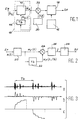
- Figures 1 to 3 attached show schematically the structure and functioning of a spread spectrum transmitter and receiver running in DPSK. This state of the art corresponds to document FR-A-2 712 129.
- FIG. 1 first of all, shows the block diagram of a transmitter.
- This transmitter has an input Ee, which receives the data b k to be transmitted and it comprises a differential encoder 10, composed of a logic circuit 12 and a delay circuit 14; the transmitter also comprises a generator 30 of pseudo-random sequences, a multiplexer 32, a local oscillator 16 and a modulator 18 connected to an output Se, which delivers the signal DPSK.
- the logic circuit 12 receives the binary data b k and delivers binary data d k .
- Logic circuit 12 also receives data delayed by a rank, ie d k-1 .
- the pseudo-random sequence used on transmission to modulate the data must have an autocorrelation function having a marked peak (of value N) for zero delay and the lowest possible side lobes. This can be achieved by using maximum length sequences (also called m-sequence) or so-called GOLD or KASAMI sequences for example.
- This pseudo-random sequence denoted ⁇ C 1 ⁇ , has a bit rate N times higher than the bit rate of the binary data to be transmitted.
- the duration T c of a binary element of this pseudo-random sequence, an element also called "chip” is therefore equal to T b / N.
- the chip flow of the pseudo-random sequence maybe several millions, even several tens of millions per second.
- FIG. 2 attached shows the block diagram of a corresponding receiver, of the differential demodulator type.
- This receiver has an input Er and includes a suitable filter 20, the impulse response of which is the time reverse of the pseudo-random sequence used in the transmitter, a delay circuit of duration T b referenced 22, a multiplier 24, an integrator 26 over a period T b and a decision logic circuit 28.
- the receiver has an output Sr which restores the data.
- the multiplier 24 receives the filtered signal x F (t) and the filtered-delayed signal x F (tT b ).
- the product is integrated over a period less than or equal to T b in the integrator 26, which delivers a signal whose polarity makes it possible to determine the value of the transmitted bit.
- the matched filter 20 therefore performs the correlation between the signal applied to its input and the sequence pseudo-random spreading.
- the signal x F (t) will therefore be in the form of a pulse signal, the repetition frequency of the pulses being equal to 1 / T b .
- the envelope of this signal is the autocorrelation function of the signal c (t).
- the information is conveyed by the phase difference between two successive correlation peaks.
- the output of the multiplier will therefore be formed of a succession of positive or negative peaks, depending on the value of the transmitted bit.
- the output of the matched filter will be formed by a succession of correlation peaks, each peak corresponding to a propagation path.
- Line (a) represents the filtered signal x F (t); line (b) the correlation signal x F (t) * x F (tT b ); line (c) the signal at the output of the integrator.
- circuits are marketed in the form of the Company's STEL 200A circuit American STANDFORD TELECOM or in the form of circuit S 20043 of the American company AMI.
- the object of the present invention is to remedy these disadvantages.
- Document DE 3735374 describes an exemplary embodiment, with components digital, a suitable filter used in a communication system spread spectrum
- the invention provides a circuit which allows to modify the characteristics linked to the pseudo-random sequence, i.e. essentially its length and its definition.
- the circuit of the invention is designed to be able to be mounted in cascade. All the circuits of the waterfall are then behaves, in a way, as a single circuit, defining a sequence global pseudo-random which is formed by the various sequences placed end to end.
- the present invention also relates to a circuit which includes a plurality of circuits such as the one just defined, these circuits being cascaded.
- the first circuit (C1) of the cascade receives, on a general entrance, the first and second parts (I, Q) of the received signal; each waterfall circuit which is not at one end of the cascade has its filtering and delay outputs connected to the circuit filter and delay inputs which follows, each of the filtering means, adding to its result, by a summation circuit, the result of filtering means of the previous circuit and transmitting the sum at the input of the circuit filtering means next.
- the overall pseudo-random sequence used in such a cascade receiver is then made up of all the sequences pseudo-random used in each of the circuits, the last circuit of the waterfall being the only one to have its multiplication circuit and its integration circuit and clock regeneration activated, the latter integration circuit restoring the information on its way out.
- Signal processing s (t) can therefore be carried out by the double treatment of parts I (t) and Q (t) that will be noted more simply, thereafter, I and Q.
- the processors which process such signals generally receive, on two separate inputs, the signals I and Q. These signals are obtained by multiplying the reception signal by a wave either in phase with the carrier or in quadrature with the latter.
- the processors then carry out various treatments according to the modulations used. We thus find, in the case of differential phase modulation, treatments which consist in forming the sum or the difference of the products of delayed samples, such as for example: I k I k-1 + Q k Q k-1 and Q k I k-1 -I k Q k-1 where k denotes the rank of a sample.
- the first expression is called "Dot” and the second "Cross” in English terminology, we can easily show that the product of a sample of rank k of the signal s (t), or s (k), by the previous conjugate sample, ie s * (k-1), product which is calculated in the receiver to demodulate the signal (see multiplier 24 in Figure 2), is within one fixed phase rotation, of the form: Dot (k) + jCross (k).
- the "Dot” product allows the determination of the phase difference between two successive symbols, while the “Dot” and “Cross” products, taken together, allow determine the integer number of times ⁇ / 2 of the phase shift between successive symbols. These "Dot” products and “Cross” therefore allow the correct demodulation and unambiguously when a differential modulation of phase was used on transmission.
- a spread spectrum signal receiver therefore first forms the parts in phase and in quadrature I and Q and then performs filtering adapted and a correlation on each of these signals. AT from the samples obtained, the receiver calculates the "Dot” and "Cross” signals and, from there, restores the information carried by the received signal.
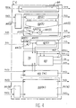
- This circuit includes two similar routes, one treating part I in phase and the other part Q in quadrature.
- the references of the means constituting these two channels are assigned an index I or an index Q, depending on whether you belong to the first or second way.
- this circuit includes seven inputs, namely: three inputs for channel I, (respectively Ed (I) which is a data entry and two entries Es (I) and Er (I) which are signal inputs filtered and filtered-delayed respectively), three inputs for channel Q, (respectively Ed (Q), Es (Q) and Er (Q)) and finally a seventh entry, Eprog, which allows enter programming data.
- the circuit also includes eleven exits, namely: three outputs for channel I, (respectively Sd (I) for the data, Ss (I) for the filtered signal and Sr (I) for filtered-delayed signal), three outputs for channel Q, (i.e. Sd (Q), Ss (Q) and Sr (Q)), a signal output "Dot” or direct product, ie S (Pdir), a "Cross” or cross product signal output S (Pcrois), a clock output SH, an output information Sinfo, and finally a Spro output from programming.
- circuit of figure 4 When the circuit of figure 4 is the only one receiver circuit, some inputs are inoperative, such as the entries Es (I), Er (I), Es (Q) and Er (Q), as well as some outputs like Spro, Sd (I), Ss (I), Sr (I), Sd (Q), sS (Q), Sr (Q).
- the circuit shown in Figure 4 includes another integration and regeneration circuit clock 80 receiving the sum of the direct products and the difference of cross products.
- the circuit of the Figure 4 also includes a digital means of programming 90 containing information suitable for program in particular the first and second means of filtering 50 (I), 50 (Q).
- the first and second digital means 50 (I) and 50 (Q), suitable for fulfill the first and second functions of filtering include (only the means of the first channel are shown) a shift register 51 (I), a adder-subtractor 52 (I), a door 53 (I) having a control input 54 (I) and a signal input 55 (I) receiving a filtered signal from the input Es (I) and a summing circuit 56 (I) having a first input connected to the output of the adder-subtractor 52 (I) and a second input connected to the exit from door 53 (I).
- the first and second digital means 60 (I), 60 (Q) capable of filling the first and second delay functions understand (only the means of the first way are shown) a multiplexer 62 (I) with an input connected to the output of the summing circuit 56 (I) and a other input connected to the delayed signal input Er (I), and a direct access memory 61 (I) to an input connected at the output of multiplexer 62 (I) and an output Sr (I) delivering a delayed signal.
- the two routes further comprise a first and a second shaping and summation 90 (I), 90 (Q) arranged in front, respectively, the first and second filtering means 50 (I), 50 (Q).
- the digital programming means 90 comprises a shift register to an Epro input and outputs connected to the first and second shift registers two channels, also connected to the first and second adder-subtractors 52 (I) of the first and second filtering means 50 (I), 50 (Q), still connected to the first entries 54 (I) of the first and second doors 53 (I) of the first and second delay means 60 (I), 60 (Q) and finally connected by means of multiplication 70 and integration means 80.
- Blocks 70 and 80 gather data in base bands and construct correlation peaks; they deduce binary information corresponding to the message received. Information is available on the Sinfo output.
- the block 90 intervenes in the configuration of the circuit and allows you to freeze the different parameters. He does not have direct role in data processing.
- block 95 i.e. block 95 (I) for channel I and block 95 (Q) for channel Q
- block 95 (I) for channel I and block 95 (Q) for channel Q) is a summator placed at the head of each way. It allows to take into account from 1 to 5 samples per chip period. The data taken in account is the raw baseband information digitized on 4 bits, at a frequency sampling.
- Block 50 allows to perform the appropriate filtering of the data delivered by the head adder. It implements registers to create a neighborhood of up to 128 data and adders-subtractors for realize the convolution function: each data is multiplied by a coefficient of the sequence pseudo-random and all 128 products obtained is summoned.
- the filter block to hold account of the cascadable aspect of the component, has an additional adder 56 (respectively 56 (I), 56 (Q)) allowing the partial result of the previous neighboring circuit (by the inputs Es (I) and Es (Q)) with its own calculation, and transmits the result to the next circuit (via the outputs Ss (I) and Ss (Q)).
- the information passing through these circuits is coded on 8 bits.
- Block 60 (respectively 60 (I) and 60 (Q) has for function of delaying the result of the adapted filtering.
- the information taken into account are those that come from the add-subtract.
- the delay is realized thanks to a direct access type memory (or RAM) to double entry: the first entry is used in write (information to be delayed) and the other in read (delayed information), the difference between the two addresses corresponding to the desired delay.
- the information is then transmitted to block 70 of multiplication.
- This multiplication block 70 performs a complex multiplication between the result of the filtering and the same delayed information.
- the main operators used for these calculations are four 8-bit multipliers and two adders. The results are brought back on a 10-bit dynamic.
- Block 80 permanently scans the transmitted data by block 70 on exit S (Pdir). It detects and tracks correlation peaks to record a Hinfo clock clocked at frequency symbol Ts; he integrates the sum signal of direct products in a time range centered around the highest peak amplitude to produce the binary data representing information. It appears on the Sinfo output.
- the general circuit configuration is ensured by block 90.
- the different parameters such as the length of the sequence, the values of the coefficients binaries of the pseudo-random sequence, setting cascade of computing units, managing the whole data paths, integration time, are configurable.
- a shift register for example of 253 bits contains the appropriate information. This register is loaded before using the circuit.
- the configuration bits are presented serially by the Eprog entry.
- FIG. 5 shows an embodiment of the circuit 80 for clock integration and regeneration.
- This circuit includes a detection means 100, a clock regeneration means 102 and an integration means 104.
- the circuit 80 has two first inputs E SPD and E DPC which receive from circuit 70, respectively, the sum of the direct products (or “Dot") and the difference of cross products (or “Cross").
- Circuit 80 also has two setpoint inputs, respectively Ec1 and Ec2, which receive from circuit 90 information on the start of integration and on the length of integration.
- the circuit 80 includes two outputs, SH delivering a clock signal and Sinfo delivering the restored information.
- the means 102 essentially comprises a counter 103 incrementing each chip period (Tc).
- the minimum counter value is set to either 0 or 1, or 2.
- the capacity of the counter corresponds to total number of chips in a sequence, in other words at the length of the sequence, ie lseq. The duration of this sequence is equal to Ts.
- the period of the counter is precisely Ts, the symbol period. Setting the minimum value to a value other than 1, namely 0 or 2, allows increase or reduce the counter period by one chip period, ie Tc.
- the content of the counter iterates through all the values from 0 to lseq, the period of counter is equal to Ts + Tc; when the content of counter goes from 2 to lseq, the period is equal to Ts-Tc.
- an H signal goes from 1 to 0 (falling edge).
- the signal H goes from 0 to 1 (rising edge).
- FIG. 6 illustrates this operation with, in top, (a) the variation of the content of the counter in depending on the number of chips received and, at the bottom, (b) the clock signal H.
- the means 100 make it possible to follow the peaks of correlation. They basically include a comparator 110 and a register 112.
- the comparator 110 makes it possible to detect a peak of high amplitude in a range corresponding to the half-period symbol (Ts / 2).
- the position of the peak relative to the rising edge of the clock signal H will adjust the counter 103 by adding or subtracting 1 from the most small counter.
- the maximum necessary synchronization time is defined by the product of Ts by the number of chips per half symbol.
- the data is returned by the medium 104 which essentially comprises an accumulator 114. Accumulation is made from the time when the value of the counter 103 producing the clock H is equal to the signal marking the start of integration (entry Ec1). Accumulation is activated as long as the value of the counter generating the clock H is lower to the sum of the signals indicating the start of integration and integration length (entry Ec2). Once the accumulation is complete, the sign of the accumulated data determines the value of the information which will be issued on the next rising edge of H. If the result of the accumulation is negative, the information will be equal to "0", otherwise the information issued will be equal to "1".
- a synchronization signal may indicate that there has synchronization between high amplitude peaks and the integration range, that is to say that the information binary resulting from the accumulation is significant.
- Figure 7 illustrates the case where three circuits identical are cascaded, i.e. C1, C2, C3.
- the inputs of the first circuit C1 receive the data I and Q of the signal by their inputs Ed (I) and Ed (Q).
- the outputs of this first C1 circuit are connected directly to the corresponding entries of the second circuit, that is C2.
- the outputs of C2 are linked to the corresponding C3 inputs.
- Only the circuit C3 has its 70 multiplication circuits and 80 integration activated, the other circuits C1 and C2 having their corresponding resources deactivated.
- door 53 is open, from so that the chaining occurs between the adder 56 and the output of the filtering means of the previous circuit.
- the last C3 circuit is the only one have the final result regarding filtering. This result appears on the outputs Ss (I) and Ss (Q) and these results are fed back into the first circuit, by the entries Es (I) and Es (Q).
- the delay blocks 60 are also chained and form a delay corresponding to all the sequences placed end to end.
- summation means 95 only the means of the first circuit C1 are used.
- the other means of the other circuits C2, C3 are transparent.
- the invention is not limited to the cascading of three circuits, but may include any number of circuits. It is not limited either sequences of 128 chips but can use sequences of any length.
Landscapes
- Engineering & Computer Science (AREA)
- Computer Networks & Wireless Communication (AREA)
- Signal Processing (AREA)
- Digital Transmission Methods That Use Modulated Carrier Waves (AREA)
Description
- "CDMA Principles of Spread Spectrum Communication", par Andrew J. VITERBI, Addison-Wesley Wireless Communications Series ;
- "Spread Spectrum Communications", par Marvin K. SIMON et al., vol. I, 1983, Computer Science Press ;
- "Spread Spectrum Systems", par R.C. DIXON, John WILEY and Sons.
- "Direct-sequence Spread Spectrum with DPSK Modulation and Diversity for Indoor Wireless Communications", publié par Mohsen KAVEHRAD et Bhaskar RAMAMURTHI dans la revue "IEEE Transactions on Communications", vol. COM 35, n°2, février 1987 ;
- Practical Surface Acoustice Wave Devices", par Melvin G. HOLLAND, dans la revue Proceedings of the IEEE, vol. 62, n°5, mai 1974, pp. 582-611.
- la discrétion : cette discrétion est liée à l'étalement de l'information transmise sur une large bande de fréquence ; il en résulte une faible densité spectrale de la puissance émise ;
- l'accès multiple : plusieurs liaisons à étalement de spectre par séquence directe peuvent partager la même bande de fréquence en utilisant des séquences pseudoaléatoires d'étalement orthogonales (séquences possédant une fonction d'intercorrélation qui présente du bruit résiduel très faible pour tous les décalages) ; cette technique, qui porte le nom d'accès multiple par les codes (AMRC en abrégé ou CDMA en anglais) est difficile à mettre en oeuvre car elle impose un réglage délicat de la puissance émise (un récepteur d'une liaison ne doit pas être aveuglé par un émetteur voisin d'une autre liaison) ;
- une bonne cohabitation avec les communications à bande étroite classique : en effet, la même bande de fréquence peut être partagée par les systèmes utilisant une modulation à bande étroite et ceux qui utilisent une modulation à large bande ; les communications à bande étroite ne voient qu'une légère augmentation du bruit radioélectrique ambiant, d'autant plus faible que la longueur de la séquence sera grande ; les communications à modulation à étalement de spectre opèrent une réjection des modulations à bande étroite grâce à l'opération de corrélation effectuée à la réception ;
- la difficulté d'interception : une transmission à étalement de spectre par séquence directe est difficile à intercepter en raison de la faible densité spectrale et du fait que le récepteur doit connaítre la séquence d'étalement pour pouvoir moduler les données ;
- un excellent comportement dans un environnement multi-trajet : dans ce type d'environnement, la propagation de l'onde radioélectrique s'effectue selon des trajets multiples qui mettent en jeu des phénomènes de réflexion, de diffraction et de diffusion ; en outre, il n'est pas rare qu'il n'y ait plus de trajet direct stable dans le temps entre l'émetteur et le récepteur ; cette propagation par trajets multiples induit des effets parasites qui tendent à dégrader la qualité de la transmission.
- "Design and experimental results for a direct-sequence spread-spectrum radio using differential phase shift keying modulation for wireless communications" de M. KAVEHRAD et al., publié dans IEEE Journal on SAC, vol. SAC 5, juin 1987, pp. 815-823 ;
- "Practical Surface Acoustic Wave Devices", de Melvin G. HOLLAND, publié dans Proceedings of the IEEE, vol. 62, n°5, mai 1974, pp. 582-611.
- un premier corrélateur assurant la fonction de filtrage adapté (corrélation entre un signal appliqué à son entrée et la séquence pseudoaléatoire),
- un second corrélateur dont le signal de sortie est retardé d'une durée égale à la durée d'un symbole ; dans ce cas, le retard est un retard engendré par le temps de propagation de l'onde acoustique le long du substrat.
- comme la séquence pseudoaléatoire est fixée par le composant à ondes acoustiques de surface, à travers la forme des électrodes, il n'est pas possible d'en changer ; autrement dit, le composant n'est pas programmable ;
- les pertes d'insertion dues à ce composant sont très grandes (environ 40 dB) ; ; elles entraínent une complexité accrue de l'étage amplificateur ;
- le coût de réalisation est élevé et le délai de fabrication long ;
- la longueur de la séquence pseudoaléatoire se trouve limitée, en raison de la taille limitée du composant à ondes acoustiques de surface ; la limite se situe à environ 512 chips.
- deux premières entrées, l'une reliée à la sortie des premiers moyens numériques de filtrage et recevant un premier signal filtré et l'autre reliée à la sortie des premiers moyens aptes à remplir la fonction de retard et recevant un premier signal filtré-retardé,
- deux secondes entrées, l'une reliée à la sortie des seconds moyens numériques de filtrage et recevant un second signal filtré et l'autre reliée à la sortie des seconds moyens aptes à remplir la fonction retard et recevant un second signal filtré-retardé,
- des moyens pour calculer les deux produits directs entre signaux filtrés et filtrés-retardés de la première et de la seconde voies et les deux produits croisés entre signal filtré d'une voie et signal filtré-retardé de l'autre voie,
- des moyens pour calculer la somme des produits directs et la différence des produits croisés,
- la figure 1, déjà décrite, est un schéma synoptique d'un émetteur connu à étalement de spectre ;
- la figure 2, déjà décrite, est un schéma synoptique d'un récepteur connu à étalement de spectre ;
- la figure 3, déjà décrite, illustre le fonctionnement général d'un récepteur ;
- la figure 4 montre la structure générale d'un circuit conforme à l'invention ;
- la figure 5 montre la structure générale du bloc d'intégration et de régénération d'un signal d'horloge ;
- la figure 6 illustre le fonctionnement du bloc précédent ;
- la figure 7 illustre un récepteur différentiel comprenant une cascade de circuits tels que celui de la figure 4.
- deux premières entrées, l'une reliée à la sortie des premiers moyens numériques 50(I) de filtrage et recevant un premier signal filtré Ik et l'autre reliée à la sortie des premiers moyens aptes à remplir la fonction de retard 61(I) et recevant un premier signal filtré-retardé Ik-1,
- deux secondes entrées, l'une reliée à la sortie des seconds moyens numériques 50(Q) de filtrage et recevant un second signal filtré Qk et l'autre reliée à la sortie des seconds moyens aptes à remplir la fonction retard 61(Q) et recevant un second signal filtré-retardé Qk-1,
- des moyens pour calculer les deux produits directs entre signaux filtrés et filtrés-retardés de la première et de la seconde voies à savoir IkIk-1 et QkQk-1, et les deux produits croisés entre signal filtré d'une voie et signal filtré-retardé de l'autre voie, à savoir QkIk-1, et IkQk-1,
- des moyens pour calculer la somme des produits directs, soit IkIk-1+QkQk-1 et la différence des produits croisés, soit QkIk-1-IkQk-1.
Claims (8)
- Circuit numérique pour récepteur différentiel de signal à étalement de spectre par séquence directe, ce signal correspondant à une émission d'une porteuse qui a été modulée par des symboles binaires véhiculant une information, ces symboles ayant été multipliés par une séquence pseudoaléatoire, ce circuit comprenant :a) une première voie de traitement numérique recevant une première partie (I) du signal reçu, cette première partie étant la partie en phase avec la porteuse, cette première voie comprenant :i) des premiers moyens numériques (50(I)) aptes à remplir une première fonction de filtrage adapté correspondant à une séquence pseudoaléatoire utilisée à l'émission,ii) des premiers moyens numériques (60(I)) aptes à remplir une première fonction de retard,b) une seconde voie de traitement numérique recevant une seconde partie (Q) du signal reçu, cette seconde partie étant la partie en quadrature de phase avec la porteuse, cette seconde voie comprenant :ce circuit étant caractérisé par le fait qu'il comprend aussi:i) des seconds moyens numériques (50(Q)) aptes à remplir une seconde fonction de filtrage adapté correspondant à ladite séquence pseudoaléatoire,ii) des seconds moyens numériques (60(Q)) aptes à remplir une fonction de retard,c) un circuit de multiplication (70) possédant :deux premières entrées, l'une reliée à la sortie des premiers moyens numériques (50(I)) de filtrage et recevant un premier signal filtré (Ik) et l'autre reliée à la sortie des premiers moyens aptes à remplir la fonction de retard (61(I)) et recevant un premier signal filtré-retardé (Ik-1),deux secondes entrées, l'une reliée à la sortie des seconds moyens numériques (50(Q)) de filtrage et recevant un second signal filtré (Qk) et l'autre reliée à la sortie des seconds moyens aptes à remplir la fonction retard (61(Q)) et recevant un second signal filtré-retardé (Qk-1),des moyens pour calculer les deux produits directs entre signaux filtrés et filtrés-retardés de la première et de la seconde voies (IkIk-1), (QkQk-1) et les deux produits croisés entre signal filtré d'une voie et signal filtré-retardé de l'autre voie (QkIk-1), (IkQk-1),des moyens pour calculer la somme des produits directs (IkIk-1+QkQk-1) et la différence des produits croisés (QkIk-1-IkQk-1)d) un circuit d'intégration et de régénération d'horloge (80) recevant ladite somme des produits directs et ladite différente des signaux produits croisés.
- Circuit selon la revendication 1, caractérisé par le fait qu'il comprend en outre un moyen numérique de programmation (90) contenant des informations aptes à programmer notamment les premiers et seconds moyens de filtrage (50(I), 50(Q)).
- Circuit selon la revendication 1, caractérisé par le fait que les premiers et seconds moyens numériques (50(I)) aptes à remplir une première et une seconde fonctions de filtrage comprennent un registre à décalage (51(I)), un additionneur-soustracteur (52(I)), une porte (53(I)) ayant une entrée de commande (54(I)) et une entrée de signal (55(I)) recevant un signal filtré et un circuit de sommation (56(I)) ayant une première entrée reliée à la sortie de l'additionneur-soustracteur (52(I)) et une seconde entrée reliée à la sortie de la porte (53(I)).
- Circuit selon la revendication 3, caractérisé par le fait que les premiers et seconds moyens numériques (60(I), 60(Q)) aptes à remplir une première et une seconde fonctions de retard comprennent un multiplexeur (62(I)) avec une entrée reliée à la sortie du circuit de sommation (56(I)) et une autre entrée reliée à une entrée (Er(I)) de signal retardé, et une mémoire à accès direct (61(I)) à une entrée reliée à la sortie du multiplexeur (62(I)) et une sortie (Sr(I)) délivrant un signal retardé.
- Circuit selon la revendication 1, caractérisé par le fait que le circuit d'intégration et de régénération d'horloge (80) comprend :des moyens (100) comprenant un comparateur (110) et un registre (112) pour suivre les pics de corrélation,des moyens (102) comprenant un compteur de capacité égale au nombre de chips dans la séquence pseudo-aléatoire, ce compteur émettant une impulsion (H) ayant un front montant lorsque le contenu du compteur passe à la valeur moitié de la capacité maximale du compteur et un front descendant lorsque le contenu du compteur passe à la valeur de la capacité maximale,des moyens de restitution d'information (104) comprenant un accumulateur (114) activé à partir d'un instant de début d'intégration et pendant une certaine durée, tous deux déterminés par le circuit de programmation.
- Circuit selon la revendication 1, caractérisé par le fait qu'il comprend en outre un premier et un second circuits de mise en forme et de sommation (95(I), 95(Q)) disposés devant, respectivement, les premiers et seconds moyens de filtrage (50(I), 50(Q)).
- Circuit selon la revendication 6, caractérisé par le fait que le moyen numérique de programmation (90) comprend un registre à décalage à une entrée (Epro) et des sorties reliées aux premier et second registres à décalage (51(I), 51(Q)), le premier et le second additionneur-soustracteurs (52(I), 52(Q)) des premier et second moyens de filtrage (50(I), 50(Q)), reliées également aux premières entrées (54(I), 54(Q)) de la première et seconde portes (53(I), 53(Q)) des premier et second moyens de retard (60(I), 60(Q)), reliées encore au moyen de multiplication (70) et aux moyens d'intégration (80) relié enfin aux premier et second moyens de mise en forme et de sommation (95(I), 95(Q).
- Récepteur différentiel à étalement de spectre par séquence directe, caractérisé par le fait qu'il comprend une cascade de circuits conformes à l'une quelconque des revendications 1 à 7, le premier circuit (C1) de la cascade recevant, sur une entrée générale (Ed(I), Ed(Q)), les première et seconde parties (I, Q) du signal reçu, chaque circuit de la cascade qui n'est pas à une extrémité de la cascade ayant ses sorties de filtrage (Ss(I), Ss(Q)) et de retard (Sr(I), Sr(Q)) reliées aux entrées de filtrage (Es(I), Es(Q)) et de retard (Er(I), Er(Q)) du circuit qui suit, chacun des moyens de filtrage (50(I), 50(Q)), ajoutant à son résultat, par le circuit de sommation (56(I), 56(Q)), le résultat des moyens de filtrage du circuit précédent et transmettant la somme à l'entrée des moyens de filtrage du circuit suivant, la séquence pseudoaléatoire globale utilisée dans un tel récepteur à cascade de circuits étant alors constituée par l'ensemble des séquences pseudoaléatoires utilisée dans chacun des circuits (C1, C2, C3), le premier circuit de la cascade (C1) étant le seul à avoir ses premier et second circuits de mise en forme (90(I), 90(Q)) activés, le dernier circuit de la cascade (C3) étant le seul à avoir son circuit de multiplication (70) et son circuit d'intégration et de régénération d'horloge (80) activés et ce dernier circuit d'intégration restituant alors l'information sur sa sortie (Sinfo).
Applications Claiming Priority (2)
| Application Number | Priority Date | Filing Date | Title |
|---|---|---|---|
| FR9514322 | 1995-12-04 | ||
| FR9514322A FR2742014B1 (fr) | 1995-12-04 | 1995-12-04 | Circuit numerique pour recepteur differentiel de signaux a etalement de spectre par sequence directe |
Publications (2)
| Publication Number | Publication Date |
|---|---|
| EP0778677A1 EP0778677A1 (fr) | 1997-06-11 |
| EP0778677B1 true EP0778677B1 (fr) | 2002-08-14 |
Family
ID=9485132
Family Applications (1)
| Application Number | Title | Priority Date | Filing Date |
|---|---|---|---|
| EP96402608A Expired - Lifetime EP0778677B1 (fr) | 1995-12-04 | 1996-12-02 | Circuit numérique pour récepteur différentiel de signaux à étalement de spectre par séquence directe |
Country Status (5)
| Country | Link |
|---|---|
| US (1) | US5799035A (fr) |
| EP (1) | EP0778677B1 (fr) |
| CA (1) | CA2191551A1 (fr) |
| DE (1) | DE69622974T2 (fr) |
| FR (1) | FR2742014B1 (fr) |
Families Citing this family (10)
| Publication number | Priority date | Publication date | Assignee | Title |
|---|---|---|---|---|
| FR2770060B1 (fr) * | 1997-10-22 | 1999-11-19 | Commissariat Energie Atomique | Recepteur differentiel a etalement de spectre par sequence directe avec moyens mixtes de formation d'un signal d'interferences |
| FR2770059B1 (fr) | 1997-10-22 | 1999-11-19 | Commissariat Energie Atomique | Circuit pour transmissions numeriques a etalement de spectre par sequence directe avec generation d'un signal d'interferences |
| RU2200366C2 (ru) * | 1998-07-20 | 2003-03-10 | Самсунг Электроникс Ко., Лтд. | Устройство для генерирования маски квазиортогонального кода в системе мобильной связи |
| FR2782587B1 (fr) * | 1998-08-20 | 2000-09-22 | France Telecom | Procedes de communications numeriques amrc a repartition des symboles de reference |
| US6424642B1 (en) * | 1998-12-31 | 2002-07-23 | Texas Instruments Incorporated | Estimation of doppler frequency through autocorrelation of pilot symbols |
| FR2791841B1 (fr) * | 1999-04-02 | 2001-05-11 | Commissariat Energie Atomique | Module recepteur et recepteur compose de plusieurs modules montes en cascade |
| US6356580B1 (en) | 1999-07-06 | 2002-03-12 | The United States Of America As Represented By The Secretary Of The Air Force | Direct sequence spread spectrum using non-antipodal phase shift keying |
| FR2796221B1 (fr) * | 1999-07-07 | 2002-04-12 | Sagem | Demodulateur de phase analogique-numerique |
| DE60024890T2 (de) * | 2000-09-13 | 2006-06-14 | Nortel Networks Ltd | Mehrbenutzerdetektion in einem cdma-kommunikationssystem |
| JP4278332B2 (ja) * | 2001-06-29 | 2009-06-10 | 日本電信電話株式会社 | 光送信器および光伝送システム |
Family Cites Families (8)
| Publication number | Priority date | Publication date | Assignee | Title |
|---|---|---|---|---|
| DE3735374A1 (de) * | 1987-10-19 | 1989-05-03 | Siemens Ag | Digitale korrelatorschaltung |
| US5253268A (en) * | 1990-05-24 | 1993-10-12 | Cylink Corporation | Method and apparatus for the correlation of sample bits of spread spectrum radio signals |
| US5202901A (en) * | 1991-05-21 | 1993-04-13 | General Electric Company | Digital discriminator for pulse shaped π/4 shifted differentially encoded quadrature phase shift keying |
| FR2696298B1 (fr) | 1992-07-15 | 1994-10-28 | Commissariat Energie Atomique | Composant pour récepteur ou pour émetteur-récepteur différentiel de signaux à étalement de spectre par séquence directe et émetteur-récepteur correspondant. |
| US5311544A (en) * | 1992-11-19 | 1994-05-10 | Samsung Electronics Co., Ltd. | Receiver of a direct sequence spread spectrum system |
| FR2712129B1 (fr) | 1993-11-02 | 1995-12-01 | Commissariat Energie Atomique | Procédé de transmission à modulation de phase synchrone et à étalement de spectre par séquence directe, émetteur et récepteur correspondants et composant pour ce récepteur. |
| JP2655068B2 (ja) * | 1993-12-30 | 1997-09-17 | 日本電気株式会社 | スペクトラム拡散受信機 |
| JPH07283762A (ja) * | 1994-04-05 | 1995-10-27 | Fujitsu General Ltd | スペクトラム拡散通信装置 |
-
1995
- 1995-12-04 FR FR9514322A patent/FR2742014B1/fr not_active Expired - Lifetime
-
1996
- 1996-11-12 US US08/747,262 patent/US5799035A/en not_active Expired - Fee Related
- 1996-11-28 CA CA002191551A patent/CA2191551A1/fr not_active Abandoned
- 1996-12-02 DE DE69622974T patent/DE69622974T2/de not_active Expired - Lifetime
- 1996-12-02 EP EP96402608A patent/EP0778677B1/fr not_active Expired - Lifetime
Also Published As
| Publication number | Publication date |
|---|---|
| CA2191551A1 (fr) | 1997-06-05 |
| FR2742014B1 (fr) | 1998-01-09 |
| EP0778677A1 (fr) | 1997-06-11 |
| DE69622974T2 (de) | 2003-04-30 |
| FR2742014A1 (fr) | 1997-06-06 |
| DE69622974D1 (de) | 2002-09-19 |
| US5799035A (en) | 1998-08-25 |
Similar Documents
| Publication | Publication Date | Title |
|---|---|---|
| EP0718983B1 (fr) | Modulation différentielle à étalement de spectre | |
| EP0738049B1 (fr) | Récepteur de signal à spectre étalé utilisant un seuil de détection autoadaptatif | |
| EP0778677B1 (fr) | Circuit numérique pour récepteur différentiel de signaux à étalement de spectre par séquence directe | |
| FR2737362A1 (fr) | Procede de selection des retards de propagation retenus pour recevoir des messages transmis par radiocommunication a etalement de spectre | |
| EP0917299B1 (fr) | Transmission numérique à étalement de spectre par séquence directe avec génération d'un signal d'interférences | |
| EP0845887A1 (fr) | Procédé de transmission à étalement de spectre par sequence directe, avec génération et optimisation des sequences | |
| EP0451232B1 (fr) | Procede et circuit d'acquisition de code pour recepteur de signal a spectre etale | |
| FR2813465A1 (fr) | Methode d'estimation conjointe de canal et de direction d'arrivee | |
| EP1041729B1 (fr) | Procédé de synchronisation de rythme d'un signal numérique | |
| EP0917298B1 (fr) | Récepteur différentiel à étalement de spectre par séquence directe avec moyens mixtes de formation d'un signal d'interférences | |
| EP0470352B1 (fr) | Procédé de transmission numérique à étalement de spectre par séquence directe à changement de séquences en cours de transmission, et émetteur et récepteur le mettant en oeuvre | |
| EP0911991B1 (fr) | Procédé de traitement d'un signal de transmission d'information par étalement de spectre et récepteur correspondant | |
| EP0849889B1 (fr) | Procédé de réception des signaux sur trajets multiples | |
| EP0778678B1 (fr) | Récepteur différentiel de signaux à étalement de spectre par séquence directe | |
| EP1184996B1 (fr) | Procédé de réception non cohérente DP-Mok avec combinaison de trajets multiples et récepteur correspondant | |
| FR2712129A1 (fr) | Procédé de transmission à modulation de phase synchrone et à étalement de spectre par séquence directe, émetteur et récepteur correspondants et composant pour ce récepteur. | |
| EP1252722B1 (fr) | Procede de radiocommunications amrc avec codes d'acces et recepteur correspondant | |
| EP1573933B1 (fr) | Procede et systeme de reception d'un signal ultra-large bande a nombre de trajets de propagation auto-adaptatif | |
| FR2782426A1 (fr) | Dispositif d'etalement ou de desetalement de spectre, notamment pour la transmission dans un systeme cellulaire de radiocommunications mobiles du type a acces multiple par repartition de codes | |
| EP1058402A1 (fr) | Procédé de traitement d'une réponse impulsionnelle avec seuil adaptatif et récepteur correspondant | |
| CA2364867C (fr) | Procedes et dispositif de traitement en reception d'un signal de transmission numerique a bande etalee | |
| FR2819125A1 (fr) | Dispositif d'echange de donnees numeriques dans un systeme cdma | |
| FR2739453A1 (fr) | Procede et dispositif d'elimination adaptative de fouillis dans un radar doppler a impulsions |
Legal Events
| Date | Code | Title | Description |
|---|---|---|---|
| PUAI | Public reference made under article 153(3) epc to a published international application that has entered the european phase |
Free format text: ORIGINAL CODE: 0009012 |
|
| AK | Designated contracting states |
Kind code of ref document: A1 Designated state(s): CH DE GB IT LI |
|
| 17P | Request for examination filed |
Effective date: 19971121 |
|
| GRAG | Despatch of communication of intention to grant |
Free format text: ORIGINAL CODE: EPIDOS AGRA |
|
| 17Q | First examination report despatched |
Effective date: 20011109 |
|
| GRAG | Despatch of communication of intention to grant |
Free format text: ORIGINAL CODE: EPIDOS AGRA |
|
| GRAH | Despatch of communication of intention to grant a patent |
Free format text: ORIGINAL CODE: EPIDOS IGRA |
|
| GRAH | Despatch of communication of intention to grant a patent |
Free format text: ORIGINAL CODE: EPIDOS IGRA |
|
| GRAA | (expected) grant |
Free format text: ORIGINAL CODE: 0009210 |
|
| AK | Designated contracting states |
Kind code of ref document: B1 Designated state(s): CH DE GB IT LI |
|
| REG | Reference to a national code |
Ref country code: GB Ref legal event code: FG4D Free format text: NOT ENGLISH |
|
| REG | Reference to a national code |
Ref country code: CH Ref legal event code: EP |
|
| REF | Corresponds to: |
Ref document number: 69622974 Country of ref document: DE Date of ref document: 20020919 |
|
| GBT | Gb: translation of ep patent filed (gb section 77(6)(a)/1977) |
Effective date: 20021028 |
|
| PG25 | Lapsed in a contracting state [announced via postgrant information from national office to epo] |
Ref country code: LI Free format text: LAPSE BECAUSE OF NON-PAYMENT OF DUE FEES Effective date: 20021231 Ref country code: CH Free format text: LAPSE BECAUSE OF NON-PAYMENT OF DUE FEES Effective date: 20021231 |
|
| PLBE | No opposition filed within time limit |
Free format text: ORIGINAL CODE: 0009261 |
|
| STAA | Information on the status of an ep patent application or granted ep patent |
Free format text: STATUS: NO OPPOSITION FILED WITHIN TIME LIMIT |
|
| 26N | No opposition filed |
Effective date: 20030515 |
|
| REG | Reference to a national code |
Ref country code: CH Ref legal event code: PL |
|
| PGFP | Annual fee paid to national office [announced via postgrant information from national office to epo] |
Ref country code: IT Payment date: 20061231 Year of fee payment: 11 |
|
| PG25 | Lapsed in a contracting state [announced via postgrant information from national office to epo] |
Ref country code: IT Free format text: LAPSE BECAUSE OF NON-PAYMENT OF DUE FEES Effective date: 20071202 |
|
| PGFP | Annual fee paid to national office [announced via postgrant information from national office to epo] |
Ref country code: GB Payment date: 20151125 Year of fee payment: 20 |
|
| PGFP | Annual fee paid to national office [announced via postgrant information from national office to epo] |
Ref country code: DE Payment date: 20151230 Year of fee payment: 20 |
|
| REG | Reference to a national code |
Ref country code: DE Ref legal event code: R071 Ref document number: 69622974 Country of ref document: DE |
|
| REG | Reference to a national code |
Ref country code: GB Ref legal event code: PE20 Expiry date: 20161201 |
|
| PG25 | Lapsed in a contracting state [announced via postgrant information from national office to epo] |
Ref country code: GB Free format text: LAPSE BECAUSE OF EXPIRATION OF PROTECTION Effective date: 20161201 |