EP0776643A1 - Computer controlled smart phacoemulsification method and apparatus - Google Patents
Computer controlled smart phacoemulsification method and apparatus Download PDFInfo
- Publication number
- EP0776643A1 EP0776643A1 EP97101751A EP97101751A EP0776643A1 EP 0776643 A1 EP0776643 A1 EP 0776643A1 EP 97101751 A EP97101751 A EP 97101751A EP 97101751 A EP97101751 A EP 97101751A EP 0776643 A1 EP0776643 A1 EP 0776643A1
- Authority
- EP
- European Patent Office
- Prior art keywords
- transducer
- mechanical impedance
- amount
- aspiration
- power
- Prior art date
- Legal status (The legal status is an assumption and is not a legal conclusion. Google has not performed a legal analysis and makes no representation as to the accuracy of the status listed.)
- Granted
Links
Images


Classifications
-
- A—HUMAN NECESSITIES
- A61—MEDICAL OR VETERINARY SCIENCE; HYGIENE
- A61B—DIAGNOSIS; SURGERY; IDENTIFICATION
- A61B17/00—Surgical instruments, devices or methods, e.g. tourniquets
- A61B17/20—Surgical instruments, devices or methods, e.g. tourniquets for vaccinating or cleaning the skin previous to the vaccination
-
- A—HUMAN NECESSITIES
- A61—MEDICAL OR VETERINARY SCIENCE; HYGIENE
- A61F—FILTERS IMPLANTABLE INTO BLOOD VESSELS; PROSTHESES; DEVICES PROVIDING PATENCY TO, OR PREVENTING COLLAPSING OF, TUBULAR STRUCTURES OF THE BODY, e.g. STENTS; ORTHOPAEDIC, NURSING OR CONTRACEPTIVE DEVICES; FOMENTATION; TREATMENT OR PROTECTION OF EYES OR EARS; BANDAGES, DRESSINGS OR ABSORBENT PADS; FIRST-AID KITS
- A61F9/00—Methods or devices for treatment of the eyes; Devices for putting-in contact lenses; Devices to correct squinting; Apparatus to guide the blind; Protective devices for the eyes, carried on the body or in the hand
- A61F9/007—Methods or devices for eye surgery
- A61F9/00736—Instruments for removal of intra-ocular material or intra-ocular injection, e.g. cataract instruments
- A61F9/00745—Instruments for removal of intra-ocular material or intra-ocular injection, e.g. cataract instruments using mechanical vibrations, e.g. ultrasonic
-
- A—HUMAN NECESSITIES
- A61—MEDICAL OR VETERINARY SCIENCE; HYGIENE
- A61M—DEVICES FOR INTRODUCING MEDIA INTO, OR ONTO, THE BODY; DEVICES FOR TRANSDUCING BODY MEDIA OR FOR TAKING MEDIA FROM THE BODY; DEVICES FOR PRODUCING OR ENDING SLEEP OR STUPOR
- A61M1/00—Suction or pumping devices for medical purposes; Devices for carrying-off, for treatment of, or for carrying-over, body-liquids; Drainage systems
- A61M1/71—Suction drainage systems
- A61M1/74—Suction control
-
- A—HUMAN NECESSITIES
- A61—MEDICAL OR VETERINARY SCIENCE; HYGIENE
- A61B—DIAGNOSIS; SURGERY; IDENTIFICATION
- A61B17/00—Surgical instruments, devices or methods, e.g. tourniquets
- A61B2017/00017—Electrical control of surgical instruments
- A61B2017/00022—Sensing or detecting at the treatment site
- A61B2017/00026—Conductivity or impedance, e.g. of tissue
- A61B2017/0003—Conductivity or impedance, e.g. of tissue of parts of the instruments
-
- A—HUMAN NECESSITIES
- A61—MEDICAL OR VETERINARY SCIENCE; HYGIENE
- A61B—DIAGNOSIS; SURGERY; IDENTIFICATION
- A61B17/00—Surgical instruments, devices or methods, e.g. tourniquets
- A61B2017/00017—Electrical control of surgical instruments
- A61B2017/00022—Sensing or detecting at the treatment site
- A61B2017/00106—Sensing or detecting at the treatment site ultrasonic
-
- A—HUMAN NECESSITIES
- A61—MEDICAL OR VETERINARY SCIENCE; HYGIENE
- A61B—DIAGNOSIS; SURGERY; IDENTIFICATION
- A61B17/00—Surgical instruments, devices or methods, e.g. tourniquets
- A61B2017/00017—Electrical control of surgical instruments
- A61B2017/00115—Electrical control of surgical instruments with audible or visual output
- A61B2017/00128—Electrical control of surgical instruments with audible or visual output related to intensity or progress of surgical action
-
- A—HUMAN NECESSITIES
- A61—MEDICAL OR VETERINARY SCIENCE; HYGIENE
- A61B—DIAGNOSIS; SURGERY; IDENTIFICATION
- A61B90/00—Instruments, implements or accessories specially adapted for surgery or diagnosis and not covered by any of the groups A61B1/00 - A61B50/00, e.g. for luxation treatment or for protecting wound edges
- A61B90/06—Measuring instruments not otherwise provided for
- A61B2090/064—Measuring instruments not otherwise provided for for measuring force, pressure or mechanical tension
-
- A—HUMAN NECESSITIES
- A61—MEDICAL OR VETERINARY SCIENCE; HYGIENE
- A61M—DEVICES FOR INTRODUCING MEDIA INTO, OR ONTO, THE BODY; DEVICES FOR TRANSDUCING BODY MEDIA OR FOR TAKING MEDIA FROM THE BODY; DEVICES FOR PRODUCING OR ENDING SLEEP OR STUPOR
- A61M1/00—Suction or pumping devices for medical purposes; Devices for carrying-off, for treatment of, or for carrying-over, body-liquids; Drainage systems
- A61M1/71—Suction drainage systems
- A61M1/77—Suction-irrigation systems
Definitions
- the present invention relates to a computer controlled "smart" phacoemulsification apparatus, and more specifically to one which controls power delivery to the needle of the transducer and also controls an amount of aspiration based on a load on the tip of the transducer.
- Phacoemulsification is not in itself new, but as currently done has many problems.
- Phacoemulsification involves the generation of an ultrasonic signal which is a series of cyclical mechanical vibrations in a frequency range beyond that detectable by normal human hearing.
- the ultrasonic signal is generated by a transducer that is driven by an electrical signal in a frequency range between 20 and 100 kilohertz in equipment presently available for this application.
- the transducer mechanism includes either piezoelectric or magnetostrictive elements.
- the energy resulting from the ultrasonic signal is coupled to the human lens by a needle attached to the transducer.
- the needle is made from an inert alloy of titanium or stainless steel.
- the ultrasonic energy fragments and emulsified the cataract. Once this nuclear material is fragmented, however, it must be removed from the eye.
- the ultrasonic needle is hollow, and an aspiration system is connected to the hollow area in order to remove the fragmented particles.
- a balanced salt solution is also injected in order to maintain the stability or pressure, and this infusion occurs around the vibrating titanium needle through a sleeve.
- Figure 1 shows diagrammatically a human lens which has an outer, fine, transparent tissue or capsule shown as layer 100.
- Anterior to this is a soft material known as the cortex 102, which surrounds the transition layers 104.
- the nucleus of the lens is a hard, compressed lens material shown as 106.
- the inventor of the present invention has first noted that in these soft outer cortical layers, little aspiration is required, but more aspiration is required in the harder transitional layers and even more in the hardest nucleus layer. However, posterior to the hardest nucleus layer is a less hard transitional layer followed by a soft cortex.
- Eye surgery involves forming an opening in the front of the capsule, and locating the phaco needle first into the soft cortex. At this time the needle will experience a minimal load in the soft cortex. As the needle goes further into the nucleus which is progressively harder, the mechanical load increases. After passing through the nucleus, the process reverses, and the mechanical load will quickly decrease. It is at this point that the inventor of the present invention has found that the control of aspiration becomes critical. Over-aspiration at this time can cause the posterior capsule to be ruptured. However, determination of the relative hardness of these layers has previously been left to the observation skills and manual skills of the surgeon. However, the surgeon has many other things on his mind and also simply may not be able to react fast enough in order to properly change the aspiration amount.
- the inventor of the present invention has recognized that a hard nucleus consumes more energy than a soft nucleus, thereby changing the impedance, and more specifically the mechanical impedance, introduced to the ultrasonic tip. According to the present invention, this difference is fed back to a microprocessor in order to modify the aspiration system dependent on the hardness of the material being operated upon. This reduces the problem of "punch through” because it allows automatic checking of the hardness of the material and automatic adjustment of the aspiration delivery in a way which is faster than could ever be done using human reflexes. Such a system has never been described in the prior art. One way in which this is done is by detecting mechanical impedance of the tissue, using, for example, a sensor to detect response to a stimulus.
- One general feature of the present invention is the recognition by the inventor of the present invention that soft tissue requires a low stroke or low velocity and that hard tissue requires a high stroke and high velocity.
- the mechanical impedance of any material including the human eye is a function of the density ⁇ and sound velocity C. It usually has a resistive component R C and a reactive component X L .
- Compliant or deformable tissue presents primarily a resistive impedance to the driving force.
- Non-compliant or non-deformable tissues are primarily a reactive impedance. In other words, soft tissue will be more resistive and hard tissue will be more reactive.
- One approach to detecting mechanical impedance from a piezoelectric hand piece is to read the driving voltage and current. Here not only magnitude but also phase will be monitored where zero phase difference will indicate a resistive load on soft tissue. A large phase difference would indicate a reactive load or hard tissue.
- a typical step horn device is shown in Figure 14 with its two parts 1050 and 1052. The lengths X of the parts 1050 and 1052 are equal to one another but their areas differ by a factor of N>10.
- the part 1052 has the impedance Z0 while the part 1050 has the characteristic impedance N x Z0.
- U.S. Patent 4,223,676 is one such attempt and defines one type of ultrasonic aspirator of the type previously described above.
- Column 8 of this patent recognizes that frequency fluctuates during the course of an operation, and in order to attempt to maintain the amount of power delivery as constant, this patent teaches monitoring actual and expected parameters of the system. The difference between these two parameters is fed back in a feedback loop to control the stroke level of the vibrator. Therefore, while the power of the system is controlled, there is no teaching of controlling the amount of aspiration, and as such the problem of "punch through” would still remain in this system.
- U.S. Patent 3, 964, 487 teaches a structure which monitors the impedance of the electric cutting apparatus, and feeds back this impedance to determine the amount of power to be provided. This device does not teach controlling the amount of aspiration, and therefore would not alleviate the problem of "punch through”.
- U.S. Patent 4, 126, 137 teaches sensing of the impedance of the tissues to set the amount of drive to an electro-surgical unit.
- U.S. Patent 4,024,866 relates to a device which teaches controlling the amount of suction in a suction conduit for eye surgery.
- Column 7, lines 24 ++ teach that an upper limit is placed on the amount of suction to prevent an excessive amount of suction. While this might provide an upper limit, it does not help the user to obtain better control and better feedback within the system
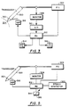
- FIG. 3 shows a first embodiment of the invention.
- Transducer 300 is shown attached to phaco needle 302 which is adapted to come into contact with a lens 304 of the human eye.
- the power supplied by power supply 306 to the transducer 300, and at the same time the voltage and current is monitored by monitor 308.
- Monitor 308 monitors the voltage and current, and produces analog signals which are converted by analog to digital converter into digital signals, and are input to microprocessor 312.
- Microprocessor 312 can be any commercially available type.
- An aspiration control 314 is also input to microprocessor as is a power supply control 316.
- Microprocessor 312 produces analog signals which control the aspiration unit 318 in the power supply 306.
- Step 400 detects voltage and current from monitor 308, and takes a ratio between this voltage and current at step 402. This ratio is stored in a variable T. This variable measures a linkage of the instantaneous aspiration with varying phaco needle load and can be implemented in at least two different forms.
- Step 404 makes a test by taking the current variable T and subtracting a previous value of the variable T called herein T P , and then determining if T - T P is greater than a value N. If it is, this means that the impedance of the tissue currently is greater than the impedance at a previous time and that the current tissue is therefore harder than the previous tissue. Therefore, if the test at step 404 is positive, step 406 is executed which increases the aspiration rate by N 1 and increases the power by N 2 . The flow then passes to step 408 in which the current value of T is stored in the location T P in preparation for a following cycle.
- Step 410 determines if the value of T P is greater than the current T by the amount N. If not, flow again passes to step 408. Therefore, if the difference between T and T P is less than the value N, no modification of aspiration or power takes place.
- T P is greater than T by more than the amount N, this indicates that the impedance at the previous time is greater than the impedance at the current time. Accordingly, the aspiration is decreased by the value N 1 and the power is decreased by the value N 2 at step 412.
- FIG. 5 A second embodiment of the invention is shown in Figure 5 where like numerals represent like elements.
- This second embodiment of the invention uses, in addition to the above monitoring system, a speech generating module 500 which enables talking to the surgeon while he is operating.
- the visual displays may show the mode in which the machine is engaged, for instance, foot pedal position and irrigation only, irrigation and aspiration, etc.
- the audio feedback may be different sounds in different units that indicate a transition, such as a beep or click.
- the second embodiment of the present invention enables the use of commercially available speech generating equipment to help avoid this confusion.
- the speech generating unit 500 can be a commercially available speech generating chip and audio equipment, or it can be, for instance, a series of tapes or recorded tracks which can be accessed by an appropriate processor. Such devices are well known in the art and will not be discussed further.
- This device operates according to the flowchart of Figure 6.
- Figure 6 has many common elements with Figure 4, and starts out in step 600 with detecting V and I and the value T.
- Step 602 determines if T is greater than T P by the value N, and if so, increases aspiration and power and also energizes speech generator 500 to say "tissue hardness increasing".
- Step 606 determines if T P is greater than T by a certain amount, and if yes, executes steps 608 by decreasing aspiration and enunciating that the tissue hardness is decreasing.
- Step 610 determines if there has been a change in aspiration or power supply control and if so, enunciates this change. For instance, a foot pedal in position one might be enunciated to say “irrigation” and in position 2 would be enunciated as “irrigation and aspiration”. The enunciator might also say “phaco fixed at 10%” or “phaco increased to 15%", and as the foot pedal or similar device was altered, then the enunciator could express, in increments, the new values.
- a third embodiment for the smart phacoemulsification system is described with reference to Figure 7 and the flowchart in Figure 8.
- the key to the successful operation of this system is twofold.
- the surgeon has independent control over both transducer load power and aspiration reference levels.
- the automatic control system power monitor and both power and aspiration compensation mechanisms provide measured improvements in the surgeon's control of the transducer by linking the aspiration system compensation with the drive signal for the power compensation.
- Electrical power supply 716 provides voltage and current at some frequency to transducer 700. Needle 702 makes contact with the human lens 704 and experiences a varying mechanical load dependent on the density of tissue layers. The surgeon establishes reference power and aspiration levels via power level control 700 and 708 aspiration level control 708. Electrical power supply 716 responds to power level commands and to power compensation commands (voltage, current or possibly frequency adjustments). These commands originate from modules 720 and 718 respectively. The varying mechanical load on needle 702 is reflected via transducer 700 as a changing electrical load consuming different amounts of electrical power from the reference power level command. This parameter detection is referred to herein as mechanical impedance.
- Power monitor 712 senses load voltage and current from transducer 700 and computes electrical power. Transducer power consumption is fed to power comparison module 714 which outputs a difference between actual transducer power and the independent reference level from the power command. Power compensation module 718 responds by appropriate electrical adjustments to power supply 716 such that transducer power consumption will track the independent command from the surgeon.
- the unique safety improvement feature of this system results from the application of the power compensation drive signal (power comparison output) to the aspiration compensation module 710.
- the output of the aspiration compensation module 710 will be an adjustment to vacuum, or flow or both, depending on the type of aspiration system.
- the Figure 8 flowchart shows detecting the transducer load and electrical power at step 800, followed by determinations at step 802 and 808 as to whether the power is less than or greater than a reference P R . If the current electrical power P L is less than P R , higher density tissue layers are recognized at step 804, followed by the aspiration increase load power at step 806. If the load P L is recognized as greater than P R at step 808, lower density tissue layers are recognized at step 810, followed by a decrease in the aspiration and step 812. Step 814 determines if no change in relative tissue density is recognized, followed by no change in load power or aspiration at step 816.
- Figure 9 shows an actual experimentally obtained mechanical impedance versus frequency spectra of loaded and unloaded phaco needles. This was measured with a Hewlett Packard impedance analyzer using ⁇ 2 volts excitation, and a hard almond, used in simulating a hardened lens portion of an eye. Figure 9 shows the change in phase and impedance shifting with loading. Two resonant peaks were observed at approximately 28.875 KHZ and 59.5 KHZ. It is believed by the applicant that these two peaks correspond to the fundamental electromechanical resonance of the piezoelectric driving crystal. These two peaks may also be due to the longitudinal and transverse piezoelectric coefficients of the crystal.
- the second impedance spectrum shown in Figure 10 shows the change in hardness effects as simulated by a chocolate covered peanut M&M (TM) candy.
- the frequency of shifts of the two resonant peaks are approximately one 1 KHZ and 375 hertz for the low and high frequency resonant peaks respectively. This demonstrates the practicability of the system by its ability to determine a peanut within a chocolate covered M&M peanut candy.
- a map will be formed between the phase angle (resonant frequency), mechanical impedance, and hardness of the material. This map can be from a plot such as shown in Figs 9 and 10, made while observing the characteristics of the material on which the operation is occurring.
- the fourth embodiment of the present invention detects the change in hardness of the material by the addition of solid state microsensors which provide the means of load hardness detection without electrical interference from the large voltages driving the piezoelectric or magnetostrictive crystal.
- Figure 11 shows a general block diagram of a structure using the process, it being understood that the concepts of all the previous embodiments could be added to the basic modification of Figure 11.
- Figure 11 shows the improved structure for load sensing defined according to the fourth embodiment.
- This fourth embodiment includes two force transducers 1000 and 1002.
- the force transducer 1000 is a driving force transducer which is driven by power supply 306 under control of microprocessor 312.
- the voltage excitation to the first force transducer 1000 causes expansion and contraction of phaco needle 302.
- An aspirator 308 and fluid supply 1003 is also provided.
- Figure 11 may also include the auxiliary structure shown in any of Figures 3-8, although this is not shown in detail for easier understanding.
- the driven element 1002 includes a separate piezoelectric crystal 1006 which is stressed at the resonant frequency of the combined electrical and mechanical circuit and for this purpose is mechanically coupled to phaco needle 302.
- This mechanical coupling provides the second piezoelectric crystal mechanically in parallel with a first piezoelectric crystal 1008 of the first force transducer 1000 to sense the movement of the needle 302 in this way.
- Needle 302 is moved by a large surge of voltage which can cause noise in the resultant measurement.
- the auxiliary crystal 1006 is moved by the movement of the needle, rather than by the driving voltage. The compression and release gives off a voltage that is proportional to this amount of compression of the piezoelectric crystal in correspondence with known characteristics of the crystal.
- the microprocessor 312 therefore obtains a voltage related to the amount of contraction of the crystal, as well as a voltage indicative of the amount of power provided to the crystal 1000, this power being coupled to the needle 302 to drive it.
- This driven element 1002 has been called a “pony” element by the inventor, since it "rides” on the phaco needle.
- the secondary sensing element 1002 is placed in a location to convert the mechanical stress thereon into electrical voltage or current. These elements can be placed at nodal points where the stress/velocity is maximum or anti-notal points where the stress/velocity is minimum.
- the signals generated by the sensors will comply with the characteristic equations for the transducer when two sensing elements are used in a differential configuration to cancel errors.
- the impedance would be continually monitored as the transducer and in another approach the transducer would pulse with the first period of the pulse being used as a sensing period of time with the following period being used as a operating period. During the sensing period the power of the transducer is lowered to a level below which cavitation will not occur and transducer losses are minimum.
- the amount of aspiration is then defined as a function of flow rate and vacuum level and either or both of these can be controlled.
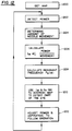
- Figure 12 starts with step 1200 of getting a map.
- This map must be determined and stored in advance, and would typically be done by making similar plots to those of Figures 9 and 10. While the simulations of Figures 9 and 10 were done with various commercially available food materials which had varying hardnesses, an actual map for the system would be better conducted using an actual human eye from a cadaver or the like. A similar simulation to that shown in Figures 9 and 10 is conducted on such an eye and a characteristic chart showing both the mechanical impedances of such a material as well as the resonant frequencies thereof should be stored as a one or two dimensional map. This map is the map that is obtained in step 1200.
- step 1202 the amount of the needle movement is detected.
- this amount of needle detection is determined by monitoring the voltage from piezoelectric crystal 1006, this voltage being proportional to the amount of movement of the needle.
- the amount of power being fed to the needle is determined at step 1202.
- Step 1204 receives a voltage from the crystal 1002, and determines the amount of needle movement as a difference between a current voltage representing a current needle position and a previous voltage representing a previous needle position.
- the mechanical impedance presented to the needle is detected according to a proportionality between power detected in step 1202 and a amount of a needle movement detected at step 1204.
- the mechanical impedance may also be weighted by a weighing factor which may be a linear factor or may be itself dependent on power or movement amount. For instance, at higher powers the mechanical impedance may a different ratio, since the material can only react by some maximum amount no matter how high the power.
- This mechanical impedance is then stored as a current value.
- a current resonant frequency is calculated based on the current amount of needle movement determined at step 1204. This may be done in many different ways, simplest among which might be to store a plurality of recent determined values and to conduct a fast Fourier transform on these values to determine current frequency components.
- the current mechanical impedance and current resonant frequency are then used to address the map to detect the part of the eye being operated on.
- step 1210 which detects this part of the eye, outputs a number which is indicative of the part of the eye currently being operated on. For instance, number 1 might mean nucleus, 2 means lens and so on.
- Step 1212 then adjusts the power output, and aspiration and fluid control to follow the part of the eye operated on.
- the way in which the amount of power would be determined is similar to the way in which the map is determined -- when using an actual model the values which cause punch-through and which are acceptable can be easily determined. Accordingly, this actual model can be used to determine what parameters output correspond to what degree of operation.
- Figure 13 shows a fifth embodiment of the present invention which is an alternative to the fourth embodiment.
- This fifth embodiment uses at least one solid state accelerometer to detect the resonant frequency characteristic of the encountered needle load.
- Figure 13 is simplified by removing all auxiliary structure used for the needle, and only shows the driving crystal 1008 and its mechanically linked accelerometer 1020.
- the microprocessor 312 receives information indicative of the amount of power driven to the crystal 1008 as well as the information from the accelerometer.
- An accelerometer is commonly available from many different sources.
- the fifth embodiment of Figure 13 would operate similarly to that explained with reference to the flow chart of Figure 12.
- the accelerometer would be used to determine how rapidly the needle accelerates and decelerates and when a harder material is hit the structure would accelerate or decelerate slower under a heavier load, thereby providing an automated detection of material hardness.
- the force meter determines how much force the needle is encountering by how much it is moving. By the detection of how much force is on the needle, one can determine mechanical impedance.
Abstract
Description
- The present invention relates to a computer controlled "smart" phacoemulsification apparatus, and more specifically to one which controls power delivery to the needle of the transducer and also controls an amount of aspiration based on a load on the tip of the transducer.
- Eye surgery is a complicated and delicate process. One common eye surgery is cataract extraction. There are currently several methods of acceptable cataract extraction, including phacoemulsification. Phacoemulsification is not in itself new, but as currently done has many problems.
- Phacoemulsification involves the generation of an ultrasonic signal which is a series of cyclical mechanical vibrations in a frequency range beyond that detectable by normal human hearing. The ultrasonic signal is generated by a transducer that is driven by an electrical signal in a frequency range between 20 and 100 kilohertz in equipment presently available for this application. Typically the transducer mechanism includes either piezoelectric or magnetostrictive elements.
- The energy resulting from the ultrasonic signal is coupled to the human lens by a needle attached to the transducer. Typically the needle is made from an inert alloy of titanium or stainless steel. Once coupled to the human lens, the ultrasonic energy fragments and emulsified the cataract. Once this nuclear material is fragmented, however, it must be removed from the eye. In order to do this, the ultrasonic needle is hollow, and an aspiration system is connected to the hollow area in order to remove the fragmented particles. A balanced salt solution is also injected in order to maintain the stability or pressure, and this infusion occurs around the vibrating titanium needle through a sleeve.
- An example of such a phacoemulsification unit is shown in U.S. Patent 4,223,676. Current phacoemulsification surgery allows the surgeon to choose either a fixed phaco mode in which the power setting to the transducer is fixed, or a linear mode in which the phaco power can be changed by the power pedal. In the fixed mode, the phaco unit is either on or off depending on whether the pedal is depressed or not. The value of power setting is preset. In the linear mode, the further depression of the pedal varies the amount of power to the transducer and thereby the ultrasonic energy. The aspiration during this operation is preset. A third mode of phacoemulsification which has been recently introduced keeps the phaco power fixed and varies the aspiration depending on the foot pedal.
- The inventor of the present invention has recognized a problem which exists in these prior operations. In order to fully understand this, one must consider the structure of the lens of the human eye. Figure 1 shows diagrammatically a human lens which has an outer, fine, transparent tissue or capsule shown as
layer 100. Anterior to this is a soft material known as thecortex 102, which surrounds thetransition layers 104. The nucleus of the lens is a hard, compressed lens material shown as 106. The inventor of the present invention has first noted that in these soft outer cortical layers, little aspiration is required, but more aspiration is required in the harder transitional layers and even more in the hardest nucleus layer. However, posterior to the hardest nucleus layer is a less hard transitional layer followed by a soft cortex. A majority of the complications during eye surgery are caused not by the amount of phacoemulsification, but by overaspiration in conjunction with the emulsification causing a "punch through" through the posterior lens capsule. This is particularly dangerous since the center of the lens needs more energy (aspiriation and emulsification) than the outer soft cortical layer, and therefore there is more possibility of punch-through at this higher energy level and high aspiration level. - Eye surgery involves forming an opening in the front of the capsule, and locating the phaco needle first into the soft cortex. At this time the needle will experience a minimal load in the soft cortex. As the needle goes further into the nucleus which is progressively harder, the mechanical load increases. After passing through the nucleus, the process reverses, and the mechanical load will quickly decrease. It is at this point that the inventor of the present invention has found that the control of aspiration becomes critical. Over-aspiration at this time can cause the posterior capsule to be ruptured. However, determination of the relative hardness of these layers has previously been left to the observation skills and manual skills of the surgeon. However, the surgeon has many other things on his mind and also simply may not be able to react fast enough in order to properly change the aspiration amount.
- The inventor of the present invention has recognized that a hard nucleus consumes more energy than a soft nucleus, thereby changing the impedance, and more specifically the mechanical impedance, introduced to the ultrasonic tip. According to the present invention, this difference is fed back to a microprocessor in order to modify the aspiration system dependent on the hardness of the material being operated upon. This reduces the problem of "punch through" because it allows automatic checking of the hardness of the material and automatic adjustment of the aspiration delivery in a way which is faster than could ever be done using human reflexes. Such a system has never been described in the prior art.
One way in which this is done is by detecting mechanical impedance of the tissue, using, for example, a sensor to detect response to a stimulus. - One general feature of the present invention is the recognition by the inventor of the present invention that soft tissue requires a low stroke or low velocity and that hard tissue requires a high stroke and high velocity. The mechanical impedance of any material including the human eye is a function of the density ρ and sound velocity C. It usually has a resistive component RC and a reactive component XL. Compliant or deformable tissue presents primarily a resistive impedance to the driving force. Non-compliant or non-deformable tissues are primarily a reactive impedance. In other words, soft tissue will be more resistive and hard tissue will be more reactive.
- One approach to detecting mechanical impedance from a piezoelectric hand piece is to read the driving voltage and current. Here not only magnitude but also phase will be monitored where zero phase difference will indicate a resistive load on soft tissue. A large phase difference would indicate a reactive load or hard tissue. Another approach would include determining the resonant frequency of the loaded hand piece in relation to a reference, which can be the resonant frequency of the unloaded hand piece. If the transducer is formed as a half wavelength straight bar, its resonant frequency will not change for purely resistive loads and can be determined according to the equation


parts parts - For a device of this type, the resonant frequency is determined according to the equation

part 1052 has the impedance Z0 while thepart 1050 has the characteristic impedance N x Z0. For purely reactive loads the resonant frequency can be determined from the equation
- These equations are general and exemplary and different needle/transducer arrangements could use different equations.
- Many attempts have been made in the prior art in order to attempt to automate operation processes. U.S. Patent 4,223,676 is one such attempt and defines one type of ultrasonic aspirator of the type previously described above. Column 8 of this patent recognizes that frequency fluctuates during the course of an operation, and in order to attempt to maintain the amount of power delivery as constant, this patent teaches monitoring actual and expected parameters of the system. The difference between these two parameters is fed back in a feedback loop to control the stroke level of the vibrator. Therefore, while the power of the system is controlled, there is no teaching of controlling the amount of aspiration, and as such the problem of "punch through" would still remain in this system.
- Similarly,
U.S. Patent 3, 964, 487 teaches a structure which monitors the impedance of the electric cutting apparatus, and feeds back this impedance to determine the amount of power to be provided. This device does not teach controlling the amount of aspiration, and therefore would not alleviate the problem of "punch through". - Similarly,
U.S. Patent 4, 126, 137 teaches sensing of the impedance of the tissues to set the amount of drive to an electro-surgical unit. - U.S. Patent 4,024,866 relates to a device which teaches controlling the amount of suction in a suction conduit for eye surgery. Column 7, lines 24 ++ teach that an upper limit is placed on the amount of suction to prevent an excessive amount of suction. While this might provide an upper limit, it does not help the user to obtain better control and better feedback within the system
- These and other aspects of the invention will now be described in detail with reference to the accompanying drawings, in which:
- Figure 1 shows a schematic view of the human eye;
- Figure 2 shows a representative amount of aspiration required in a traversal through the eye;
- Figure 3 shows a blocked diagram representation of a first embodiment of the present invention;
- Figure 4 shows a flow chart of operation of this first embodiment;
- Figure 5 shows a blocked diagram representation of a second embodiment of the present invention which uses a speech enunciator to aid the surgeon with his operation;
- Figure 6 shows a flow chart of operation of the second embodiment.
- Figure 7 shows a structure of the third embodiment of the present invention; and
- Figure 8 shows a flow chart of this operation.
- Figures 9 and 10 show characteristic curves for characteristics in Almond, and a peanut "M & M(TM)", respectively;
- Figure 11 shows a block diagram of a fourth embodiment of the invention;
- Figure 12 shows a flowchart of operation of this fourth embodiment; and
- Figure 13 shows a block diagram of a fifth embodiment of the invention; and
- Figure 14 shows a typical phaco needle.
- A presently preferred embodiment will now be described in detail with respect to the accompanying drawings. Figure 3 shows a first embodiment of the invention.
Transducer 300 is shown attached tophaco needle 302 which is adapted to come into contact with alens 304 of the human eye. The power supplied bypower supply 306 to thetransducer 300, and at the same time the voltage and current is monitored bymonitor 308.Monitor 308 monitors the voltage and current, and produces analog signals which are converted by analog to digital converter into digital signals, and are input tomicroprocessor 312.Microprocessor 312 can be any commercially available type. Anaspiration control 314 is also input to microprocessor as is apower supply control 316. These devices can be either dial-type potentiometers or the usual surgeon's foot pedal, and produce a command signal indicative of the amount of aspiration and power respectively desired.Microprocessor 312 produces analog signals which control theaspiration unit 318 in thepower supply 306. - The microprocessor operates according the flowchart of Figure 4, and accordingly controls the
aspiration 318 andpower supply 306 based on this flowchart. Step 400 detects voltage and current frommonitor 308, and takes a ratio between this voltage and current atstep 402. This ratio is stored in a variable T. This variable measures a linkage of the instantaneous aspiration with varying phaco needle load and can be implemented in at least two different forms. - First we must recognize that a positive correlation has been established between the electrical power consumed by an ultrasonic transducer and the mechanical motion of a needle attacked to it. One way, therefore, would be tracking impedance (voltage in/current in).

- A multiplier circuit could be used to accomplish this. Changes in the load would allow the control system to compensate in a variety of ways by affecting both electrical power and aspiration levels. Alternately, the difference between commanded power levels and actual power consumed could also be measured directly with only one multiplier circuit i.e.

- Both power levels (V*I) and V/I are referred to generically herein as "Impedance".
- Step 404 makes a test by taking the current variable T and subtracting a previous value of the variable T called herein TP, and then determining if T - TP is greater than a value N. If it is, this means that the impedance of the tissue currently is greater than the impedance at a previous time and that the current tissue is therefore harder than the previous tissue. Therefore, if the test at
step 404 is positive,step 406 is executed which increases the aspiration rate by N1 and increases the power by N2. The flow then passes to step 408 in which the current value of T is stored in the location TP in preparation for a following cycle. - If the result at
step 404 is negative and the difference between T and TP is not greater than N, a second test is made atstep 410. Step 410 determines if the value of TP is greater than the current T by the amount N. If not, flow again passes to step 408. Therefore, if the difference between T and TP is less than the value N, no modification of aspiration or power takes place. - If TP is greater than T by more than the amount N, this indicates that the impedance at the previous time is greater than the impedance at the current time. Accordingly, the aspiration is decreased by the value N1 and the power is decreased by the value N2 at
step 412. - The following steps, 420 and 422, follow the lead of the
aspiration controller 314 andpower supply controller 316 respectively. If these values are increased, the power to the appropriate component i also increased, according to a previously designated algorithm. - The specific structure and method steps enabling control of both power and aspiration according to the impedance encountered by the transducer is in no way taught or suggested by the prior art and is totally novel thereover.
- A second embodiment of the invention is shown in Figure 5 where like numerals represent like elements. This second embodiment of the invention uses, in addition to the above monitoring system, a
speech generating module 500 which enables talking to the surgeon while he is operating. - Current phaco units have visual displays and audio feedback. The visual displays may show the mode in which the machine is engaged, for instance, foot pedal position and irrigation only, irrigation and aspiration, etc. The audio feedback may be different sounds in different units that indicate a transition, such as a beep or click.
- However, all of these sounds may be very confusing to a surgeon who is first learning to do the phaco procedure. Such a surgeon has many other things to concentrate on and often times finds extra confusion in where on the foot pedal they are and precisely what is happening. The second embodiment of the present invention enables the use of commercially available speech generating equipment to help avoid this confusion.
- According to this embodiment of this invention, the
speech generating unit 500 can be a commercially available speech generating chip and audio equipment, or it can be, for instance, a series of tapes or recorded tracks which can be accessed by an appropriate processor. Such devices are well known in the art and will not be discussed further. This device operates according to the flowchart of Figure 6. Figure 6 has many common elements with Figure 4, and starts out instep 600 with detecting V and I and thevalue T. Step 602 determines if T is greater than TP by the value N, and if so, increases aspiration and power and also energizesspeech generator 500 to say "tissue hardness increasing". Step 606 determines if TP is greater than T by a certain amount, and if yes, executessteps 608 by decreasing aspiration and enunciating that the tissue hardness is decreasing. Step 610 determines if there has been a change in aspiration or power supply control and if so, enunciates this change. For instance, a foot pedal in position one might be enunciated to say "irrigation" and inposition 2 would be enunciated as "irrigation and aspiration". The enunciator might also say "phaco fixed at 10%" or "phaco increased to 15%", and as the foot pedal or similar device was altered, then the enunciator could express, in increments, the new values. - This would enable the surgeon to maintain his concentration during this very difficult time of the operation.
- A third embodiment for the smart phacoemulsification system is described with reference to Figure 7 and the flowchart in Figure 8. The key to the successful operation of this system is twofold. First, the surgeon has independent control over both transducer load power and aspiration reference levels. Secondly, the automatic control system power monitor and both power and aspiration compensation mechanisms provide measured improvements in the surgeon's control of the transducer by linking the aspiration system compensation with the drive signal for the power compensation.
-
Electrical power supply 716 provides voltage and current at some frequency totransducer 700. Needle 702 makes contact with thehuman lens 704 and experiences a varying mechanical load dependent on the density of tissue layers. The surgeon establishes reference power and aspiration levels viapower level control aspiration level control 708.Electrical power supply 716 responds to power level commands and to power compensation commands (voltage, current or possibly frequency adjustments). These commands originate frommodules 720 and 718 respectively. The varying mechanical load on needle 702 is reflected viatransducer 700 as a changing electrical load consuming different amounts of electrical power from the reference power level command. This parameter detection is referred to herein as mechanical impedance. - Power monitor 712 senses load voltage and current from
transducer 700 and computes electrical power. Transducer power consumption is fed topower comparison module 714 which outputs a difference between actual transducer power and the independent reference level from the power command.Power compensation module 718 responds by appropriate electrical adjustments topower supply 716 such that transducer power consumption will track the independent command from the surgeon. - The unique safety improvement feature of this system results from the application of the power compensation drive signal (power comparison output) to the
aspiration compensation module 710. The output of theaspiration compensation module 710 will be an adjustment to vacuum, or flow or both, depending on the type of aspiration system. - As with power the surgeon has independent input control via
aspiration control 708 to press the output (vacuum and flow) of aspiration system 706. The entire system follows a straightforward control scheme as described by the flowchart of Figure 8. note that any changes induced by the compensation modules will force the load power to track the independent power level command from the surgeon. Also, the aspiration changes will be added to the independent aspiration level commands from the surgeon. In this way, the surgeon maintains control over the procedure. - The Figure 8 flowchart shows detecting the transducer load and electrical power at
step 800, followed by determinations atstep step 804, followed by the aspiration increase load power atstep 806. If the load PL is recognized as greater than PR atstep 808, lower density tissue layers are recognized atstep 810, followed by a decrease in the aspiration and step 812. Step 814 determines if no change in relative tissue density is recognized, followed by no change in load power or aspiration atstep 816. - Experiments have been carried out to verify that both mechanical impedance and resonant frequency change is a function of the hardness of material that is encountered by
phaco needle 302 during such operations. Figure 9 shows an actual experimentally obtained mechanical impedance versus frequency spectra of loaded and unloaded phaco needles. This was measured with a Hewlett Packard impedance analyzer using ±2 volts excitation, and a hard almond, used in simulating a hardened lens portion of an eye. Figure 9 shows the change in phase and impedance shifting with loading. Two resonant peaks were observed at approximately 28.875 KHZ and 59.5 KHZ. It is believed by the applicant that these two peaks correspond to the fundamental electromechanical resonance of the piezoelectric driving crystal. These two peaks may also be due to the longitudinal and transverse piezoelectric coefficients of the crystal. - The second impedance spectrum shown in Figure 10 shows the change in hardness effects as simulated by a chocolate covered peanut M&M (TM) candy. The frequency of shifts of the two resonant peaks are approximately one 1 KHZ and 375 hertz for the low and high frequency resonant peaks respectively. This demonstrates the practicability of the system by its ability to determine a peanut within a chocolate covered M&M peanut candy.
- In operation, a map will be formed between the phase angle (resonant frequency), mechanical impedance, and hardness of the material. This map can be from a plot such as shown in Figs 9 and 10, made while observing the characteristics of the material on which the operation is occurring.
- While these changes in impedance can be determined and the observation of the frequency shift can also be determined as the phaco needle encounters loads of different hardness, it has been found that it may be difficult to identify these changes under high level excitation (110 volt) conditions due to the high electrical noise. The impedance and frequency shift are more easily observable under low level excitation conditions of such as ±2 volts, but detection of this on a practical scale requires more specialized techniques than those of the previous embodiments.
- In order to effect this low level process, the fourth embodiment of the present invention detects the change in hardness of the material by the addition of solid state microsensors which provide the means of load hardness detection without electrical interference from the large voltages driving the piezoelectric or magnetostrictive crystal. Figure 11 shows a general block diagram of a structure using the process, it being understood that the concepts of all the previous embodiments could be added to the basic modification of Figure 11.
- Figure 11 shows the improved structure for load sensing defined according to the fourth embodiment. This fourth embodiment includes two
force transducers force transducer 1000 is a driving force transducer which is driven bypower supply 306 under control ofmicroprocessor 312. The voltage excitation to thefirst force transducer 1000 causes expansion and contraction ofphaco needle 302. Anaspirator 308 and fluid supply 1003 is also provided. It should be understood that Figure 11 may also include the auxiliary structure shown in any of Figures 3-8, although this is not shown in detail for easier understanding. - The driven
element 1002 includes a separatepiezoelectric crystal 1006 which is stressed at the resonant frequency of the combined electrical and mechanical circuit and for this purpose is mechanically coupled tophaco needle 302. This mechanical coupling provides the second piezoelectric crystal mechanically in parallel with a firstpiezoelectric crystal 1008 of thefirst force transducer 1000 to sense the movement of theneedle 302 in this way.Needle 302 is moved by a large surge of voltage which can cause noise in the resultant measurement. However, theauxiliary crystal 1006 is moved by the movement of the needle, rather than by the driving voltage. The compression and release gives off a voltage that is proportional to this amount of compression of the piezoelectric crystal in correspondence with known characteristics of the crystal. Themicroprocessor 312 therefore obtains a voltage related to the amount of contraction of the crystal, as well as a voltage indicative of the amount of power provided to thecrystal 1000, this power being coupled to theneedle 302 to drive it. This drivenelement 1002 has been called a "pony" element by the inventor, since it "rides" on the phaco needle. - The
secondary sensing element 1002 is placed in a location to convert the mechanical stress thereon into electrical voltage or current. These elements can be placed at nodal points where the stress/velocity is maximum or anti-notal points where the stress/velocity is minimum. The signals generated by the sensors will comply with the characteristic equations for the transducer when two sensing elements are used in a differential configuration to cancel errors. - In one approach, the impedance would be continually monitored as the transducer and in another approach the transducer would pulse with the first period of the pulse being used as a sensing period of time with the following period being used as a operating period. During the sensing period the power of the transducer is lowered to a level below which cavitation will not occur and transducer losses are minimum.
- The amount of aspiration is then defined as a function of flow rate and vacuum level and either or both of these can be controlled.
- The operation of this structure takes place accordance with the flow chart of Figure 12. The flow chart of Figure 12 shows the operation of the present invention, it being understood that this operation might need to be modified somewhat. However, these modifications could easily be done by those of skill in the art by repeating the simulation discussed above with respect to Figures 9 and 10. While Figures 9 and 10 used an almond and a M&M respectively, actual values for cut-off could use an actual human eye from a cadaver or an animal for better simulating the exact characteristics that will need to be controlled.
- Figure 12 starts with
step 1200 of getting a map. This map, however, must be determined and stored in advance, and would typically be done by making similar plots to those of Figures 9 and 10. While the simulations of Figures 9 and 10 were done with various commercially available food materials which had varying hardnesses, an actual map for the system would be better conducted using an actual human eye from a cadaver or the like. A similar simulation to that shown in Figures 9 and 10 is conducted on such an eye and a characteristic chart showing both the mechanical impedances of such a material as well as the resonant frequencies thereof should be stored as a one or two dimensional map. This map is the map that is obtained instep 1200. - The actual flow chart begins with
step 1202 where the amount of the needle movement is detected. In this embodiment this amount of needle detection is determined by monitoring the voltage frompiezoelectric crystal 1006, this voltage being proportional to the amount of movement of the needle. The amount of power being fed to the needle is determined atstep 1202.Step 1204 receives a voltage from thecrystal 1002, and determines the amount of needle movement as a difference between a current voltage representing a current needle position and a previous voltage representing a previous needle position. Atstep 1206 the mechanical impedance presented to the needle is detected according to a proportionality between power detected instep 1202 and a amount of a needle movement detected atstep 1204. The mechanical impedance may also be weighted by a weighing factor which may be a linear factor or may be itself dependent on power or movement amount. For instance, at higher powers the mechanical impedance may a different ratio, since the material can only react by some maximum amount no matter how high the power. This mechanical impedance is then stored as a current value. At step 1208 a current resonant frequency is calculated based on the current amount of needle movement determined atstep 1204. This may be done in many different ways, simplest among which might be to store a plurality of recent determined values and to conduct a fast Fourier transform on these values to determine current frequency components. The current mechanical impedance and current resonant frequency are then used to address the map to detect the part of the eye being operated on. In thispreferred embodiment step 1210, which detects this part of the eye, outputs a number which is indicative of the part of the eye currently being operated on. For instance,number 1 might mean nucleus, 2 means lens and so on.Step 1212 then adjusts the power output, and aspiration and fluid control to follow the part of the eye operated on. The way in which the amount of power would be determined is similar to the way in which the map is determined -- when using an actual model the values which cause punch-through and which are acceptable can be easily determined. Accordingly, this actual model can be used to determine what parameters output correspond to what degree of operation. - Of course it should be understood in the above flow chart that many modifications are possible. For example, while the flow chart explains that both mechanical impedance or resonant frequency be used, it should be understood that either one by itself may be enough to find the current location in the eye and hence a two dimensional map of either resonant frequency or mechanical impedance could be used. While the techniques of the present invention are specifically related to operation within a human eye, it should be emphasized that these techniques could be used for operation in many other organs or in anything else.
- Figure 13 shows a fifth embodiment of the present invention which is an alternative to the fourth embodiment. This fifth embodiment uses at least one solid state accelerometer to detect the resonant frequency characteristic of the encountered needle load. Figure 13 is simplified by removing all auxiliary structure used for the needle, and only shows the driving
crystal 1008 and its mechanically linkedaccelerometer 1020. In this way, themicroprocessor 312 receives information indicative of the amount of power driven to thecrystal 1008 as well as the information from the accelerometer. An accelerometer is commonly available from many different sources. The fifth embodiment of Figure 13 would operate similarly to that explained with reference to the flow chart of Figure 12. In summary the accelerometer would be used to determine how rapidly the needle accelerates and decelerates and when a harder material is hit the structure would accelerate or decelerate slower under a heavier load, thereby providing an automated detection of material hardness. The force meter, in contrast, determines how much force the needle is encountering by how much it is moving. By the detection of how much force is on the needle, one can determine mechanical impedance. - Although only a few embodiments have been described in detail above, those having ordinary skill in the art will understand that many modifications are possible in this embodiment without detracting from the advantages of the invention. All such modifications are intended to be encompassed within the following application.
Claims (7)
- A control apparatus for a surgical transducer, which includes an aspiration port, for operating on a human part, comprising:means for monitoring mechanical impedance of the load to determine changes in characteristics of a load encountered by the surgical transducer; andmeans for controlling an operating characteristic of said transducer based on said mechanical impedance.
- A system as in Claim 1, further comprising a solid state microsensor coupled to said surgical transducer to determine an amount of movement thereof and means for calculating mechanical impedance from said amount of movement and from a power supplied to said transducer.
- A system as in Claim 2, wherein said solid state sensor is a piezoelectric element mechanically coupled to said surgical transducer.
- A system as in Claim 2, wherein said sensor is an accelerometer.
- A method of controlling an operation in a human body part comprising the steps of:forming a map between a mechanical impedance of different portions of said body part and a characteristic of a transducer which will conduct the operation which characteristic should be used for said different portions;operating the transducer to conduct said operation;detecting a mechanical impedance presented to the transducer;determining a relation between the mechanical impedance presented to the transducer with respect to a previous load presented to the transducer;automatically increasing an amount of aspiration if said mechanical impedance is greater than said previous load; andautomatically decreasing said amount of aspiration if said mechanical impedance is less than said previous load.
- An apparatus for enabling operations on a human body part comprising:memory means for storing a map between mechanical impedance of said human body parts and a characteristic to be used in operation for that mechanical impedance;a transducer, having a characteristic which can conduct the operation on said human body parts;a mechanical sensor, coupled to said transducer for detecting an amount of movement of said transducer; andprocessing means for detecting an amount of power provided to said transducer and calculating a mechanical impedance based on said amount of power and said amount of movement and for using said mechanical impedance to address said map to thereby obtain information indicative of said operation and to use said information to control said transducer.
- A system as in Claim 6, wherein said map also stores a resonant frequency of various portions of said body part and said processing means further includes means for calculating a current resonant frequency and means for using resonant frequency along with said mechanical impedance to determine said characteristic.
Applications Claiming Priority (5)
| Application Number | Priority Date | Filing Date | Title |
|---|---|---|---|
| US07/635,887 US5160317A (en) | 1991-01-03 | 1991-01-03 | Computer controlled smart phacoemulsification method and apparatus |
| US635887 | 1991-01-03 | ||
| US810428 | 1991-12-20 | ||
| US07/810,428 US5279547A (en) | 1991-01-03 | 1991-12-20 | Computer controlled smart phacoemulsification method and apparatus |
| EP92904542A EP0565640B1 (en) | 1991-01-03 | 1992-01-02 | Computer controlled smart phacoemulsification apparatus |
Related Parent Applications (2)
| Application Number | Title | Priority Date | Filing Date |
|---|---|---|---|
| EP92904542A Division EP0565640B1 (en) | 1991-01-03 | 1992-01-02 | Computer controlled smart phacoemulsification apparatus |
| EP92904542.5 Division | 1992-07-27 |
Publications (2)
| Publication Number | Publication Date |
|---|---|
| EP0776643A1 true EP0776643A1 (en) | 1997-06-04 |
| EP0776643B1 EP0776643B1 (en) | 2003-08-13 |
Family
ID=27092475
Family Applications (2)
| Application Number | Title | Priority Date | Filing Date |
|---|---|---|---|
| EP92904542A Expired - Lifetime EP0565640B1 (en) | 1991-01-03 | 1992-01-02 | Computer controlled smart phacoemulsification apparatus |
| EP97101751A Expired - Lifetime EP0776643B1 (en) | 1991-01-03 | 1992-01-02 | Computer controlled smart phacoemulsification apparatus |
Family Applications Before (1)
| Application Number | Title | Priority Date | Filing Date |
|---|---|---|---|
| EP92904542A Expired - Lifetime EP0565640B1 (en) | 1991-01-03 | 1992-01-02 | Computer controlled smart phacoemulsification apparatus |
Country Status (11)
| Country | Link |
|---|---|
| US (2) | US5279547A (en) |
| EP (2) | EP0565640B1 (en) |
| JP (1) | JP2858949B2 (en) |
| KR (2) | KR100274663B1 (en) |
| AT (2) | ATE246907T1 (en) |
| AU (3) | AU667801B2 (en) |
| CA (1) | CA2099780C (en) |
| DE (2) | DE69233165T2 (en) |
| DK (2) | DK0776643T3 (en) |
| ES (2) | ES2121007T3 (en) |
| WO (1) | WO1992011814A1 (en) |
Families Citing this family (120)
| Publication number | Priority date | Publication date | Assignee | Title |
|---|---|---|---|---|
| US5279547A (en) * | 1991-01-03 | 1994-01-18 | Alcon Surgical Inc. | Computer controlled smart phacoemulsification method and apparatus |
| US5419761A (en) * | 1993-08-03 | 1995-05-30 | Misonix, Inc. | Liposuction apparatus and associated method |
| US5591127A (en) * | 1994-01-28 | 1997-01-07 | Barwick, Jr.; Billie J. | Phacoemulsification method and apparatus |
| JP3162723B2 (en) * | 1994-01-28 | 2001-05-08 | アラーガン・セイルズ・インコーポレイテッド | Apparatus for controlling fluid irrigation and fluid aspiration in ophthalmic surgery |
| US5431664A (en) * | 1994-04-28 | 1995-07-11 | Alcon Laboratories, Inc. | Method of tuning ultrasonic devices |
| US5472447A (en) * | 1994-05-03 | 1995-12-05 | Abrams; Andrew L. | Power-assisted obturator |
| US5913848A (en) | 1996-06-06 | 1999-06-22 | Luther Medical Products, Inc. | Hard tip over-the-needle catheter and method of manufacturing the same |
| US6024725A (en) * | 1996-11-27 | 2000-02-15 | Mentor Corporation | Reducing tissue trauma and fluid loss during surgery |
| US5808396A (en) * | 1996-12-18 | 1998-09-15 | Alcon Laboratories, Inc. | System and method for tuning and controlling an ultrasonic handpiece |
| US7169123B2 (en) * | 1997-01-22 | 2007-01-30 | Advanced Medical Optics, Inc. | Control of pulse duty cycle based upon footswitch displacement |
| US6394974B1 (en) * | 1997-01-22 | 2002-05-28 | Allergan Sales, Inc. | Power mode phaco |
| US6780165B2 (en) | 1997-01-22 | 2004-08-24 | Advanced Medical Optics | Micro-burst ultrasonic power delivery |
| US6053906A (en) * | 1997-06-25 | 2000-04-25 | Olympus Optical Co., Ltd. | Ultrasonic operation apparatus |
| US6053886A (en) * | 1997-08-12 | 2000-04-25 | Medtek Devices, Inc. | Switch apparatus for operating an evacuator |
| US5938677A (en) * | 1997-10-15 | 1999-08-17 | Alcon Laboratories, Inc. | Control system for a phacoemulsification handpiece |
| CN1110292C (en) * | 1997-10-16 | 2003-06-04 | 北京中科电气高技术公司 | Cataract ultrasonic emulsifying instrument |
| US6013048A (en) * | 1997-11-07 | 2000-01-11 | Mentor Corporation | Ultrasonic assisted liposuction system |
| US6283974B1 (en) | 1997-11-14 | 2001-09-04 | Aaron James Alexander | Surgical tip for phacoemulsification |
| US6083193A (en) * | 1998-03-10 | 2000-07-04 | Allergan Sales, Inc. | Thermal mode phaco apparatus and method |
| US6986753B2 (en) | 1998-05-21 | 2006-01-17 | Buivision | Constant ocular pressure active infusion system |
| US6028387A (en) * | 1998-06-29 | 2000-02-22 | Alcon Laboratories, Inc. | Ultrasonic handpiece tuning and controlling device |
| US6200326B1 (en) * | 1999-04-28 | 2001-03-13 | Krishna Narayanan | Method and apparatus for hair removal using ultrasonic energy |
| US6179808B1 (en) | 1999-06-18 | 2001-01-30 | Alcon Laboratories, Inc. | Method of controlling the operating parameters of a surgical system |
| US7429258B2 (en) * | 2001-10-26 | 2008-09-30 | Massachusetts Institute Of Technology | Microneedle transport device |
| US6997935B2 (en) * | 2001-11-20 | 2006-02-14 | Advanced Medical Optics, Inc. | Resonant converter tuning for maintaining substantially constant phaco handpiece power under increased load |
| US6908451B2 (en) | 2002-04-25 | 2005-06-21 | Alcon, Inc. | Liquid venting surgical system |
| US7776027B2 (en) | 2002-07-11 | 2010-08-17 | Misonix, Incorporated | Medical handpiece with automatic power switching means |
| US20040092921A1 (en) * | 2002-10-21 | 2004-05-13 | Kadziauskas Kenneth E. | System and method for pulsed ultrasonic power delivery employing cavitation effects |
| US7316664B2 (en) | 2002-10-21 | 2008-01-08 | Advanced Medical Optics, Inc. | Modulated pulsed ultrasonic power delivery system and method |
| US7077820B1 (en) * | 2002-10-21 | 2006-07-18 | Advanced Medical Optics, Inc. | Enhanced microburst ultrasonic power delivery system and method |
| US20040092800A1 (en) * | 2002-11-11 | 2004-05-13 | Mackool Richard J. | System for instructing removal of cataract tissue |
| US6875210B2 (en) * | 2002-11-19 | 2005-04-05 | Conmed Corporation | Electrosurgical generator and method for cross-checking mode functionality |
| US6948503B2 (en) * | 2002-11-19 | 2005-09-27 | Conmed Corporation | Electrosurgical generator and method for cross-checking output power |
| JP2004267462A (en) * | 2003-03-07 | 2004-09-30 | Olympus Corp | Ultrasonic puncture system |
| CA2830583C (en) * | 2003-03-12 | 2015-06-09 | Abbott Medical Optics Inc. | System and method for pulsed ultrasonic power delivery employing cavitation effects |
| JP4126253B2 (en) * | 2003-06-25 | 2008-07-30 | 株式会社ニデック | Ultrasonic surgical device |
| JP2005027907A (en) * | 2003-07-07 | 2005-02-03 | Olympus Corp | Ultrasonic surgery system and probe |
| US7846126B2 (en) * | 2003-07-14 | 2010-12-07 | Abbott Medical Optics, Inc. | System and method for modulated surgical procedure irrigation and aspiration |
| DE102004014666A1 (en) * | 2004-03-19 | 2005-11-17 | Aesculap Ag & Co. Kg | Powered surgical hand tool e.g. drill or circular saw has accelerometer transducer linked to torque limiting system |
| US7297137B2 (en) * | 2004-03-22 | 2007-11-20 | Alcon, Inc. | Method of detecting surgical events |
| US7645255B2 (en) * | 2004-03-22 | 2010-01-12 | Alcon, Inc. | Method of controlling a surgical system based on irrigation flow |
| US7645256B2 (en) * | 2004-08-12 | 2010-01-12 | Alcon, Inc. | Ultrasound handpiece |
| US7811255B2 (en) * | 2004-03-22 | 2010-10-12 | Alcon, Inc. | Method of controlling a surgical system based on a rate of change of an operating parameter |
| US7572242B2 (en) * | 2004-03-22 | 2009-08-11 | Alcon, Inc. | Method of operating an ultrasound handpiece |
| US7625388B2 (en) * | 2004-03-22 | 2009-12-01 | Alcon, Inc. | Method of controlling a surgical system based on a load on the cutting tip of a handpiece |
| US7651490B2 (en) * | 2004-08-12 | 2010-01-26 | Alcon, Inc. | Ultrasonic handpiece |
| JP4724827B2 (en) * | 2005-03-24 | 2011-07-13 | 国立大学法人山口大学 | Agitation treatment device and catheter |
| US7335997B2 (en) * | 2005-03-31 | 2008-02-26 | Ethicon Endo-Surgery, Inc. | System for controlling ultrasonic clamping and cutting instruments |
| US20070167965A1 (en) * | 2006-01-05 | 2007-07-19 | Ethicon Endo-Surgery, Inc. | Ultrasonic medical instrument |
| US20070173872A1 (en) * | 2006-01-23 | 2007-07-26 | Ethicon Endo-Surgery, Inc. | Surgical instrument for cutting and coagulating patient tissue |
| US20070191712A1 (en) * | 2006-02-15 | 2007-08-16 | Ethicon Endo-Surgery, Inc. | Method for sealing a blood vessel, a medical system and a medical instrument |
| US7854735B2 (en) * | 2006-02-16 | 2010-12-21 | Ethicon Endo-Surgery, Inc. | Energy-based medical treatment system and method |
| US7785336B2 (en) | 2006-08-01 | 2010-08-31 | Abbott Medical Optics Inc. | Vacuum sense control for phaco pulse shaping |
| US8465467B2 (en) * | 2006-09-14 | 2013-06-18 | Novartis Ag | Method of controlling an irrigation/aspiration system |
| US20080172076A1 (en) * | 2006-11-01 | 2008-07-17 | Alcon, Inc. | Ultrasound apparatus and method of use |
| US8579929B2 (en) * | 2006-12-08 | 2013-11-12 | Alcon Research, Ltd. | Torsional ultrasound hand piece that eliminates chatter |
| US8109937B2 (en) * | 2007-02-23 | 2012-02-07 | Alcon Research, Ltd. | Surgical system for indication of media types |
| US8303530B2 (en) * | 2007-05-10 | 2012-11-06 | Novartis Ag | Method of operating an ultrasound handpiece |
| US20100036256A1 (en) * | 2008-08-08 | 2010-02-11 | Mikhail Boukhny | Offset ultrasonic hand piece |
| US20100094321A1 (en) * | 2008-10-10 | 2010-04-15 | Takayuki Akahoshi | Ultrasound Handpiece |
| US8083691B2 (en) | 2008-11-12 | 2011-12-27 | Hansen Medical, Inc. | Apparatus and method for sensing force |
| US7806865B1 (en) | 2009-05-20 | 2010-10-05 | Alcon Research, Ltd. | Pressurized irrigation squeeze band |
| US8623040B2 (en) | 2009-07-01 | 2014-01-07 | Alcon Research, Ltd. | Phacoemulsification hook tip |
| US8070711B2 (en) * | 2009-12-09 | 2011-12-06 | Alcon Research, Ltd. | Thermal management algorithm for phacoemulsification system |
| US8136779B2 (en) | 2010-07-27 | 2012-03-20 | Alcon Research, Ltd. | Mounting arrangement for a pressurized irrigation system |
| AU2014215954C1 (en) * | 2010-07-27 | 2017-06-01 | Alcon Inc. | Mounting arrangement for a pressurized irrigation system |
| US8784357B2 (en) | 2010-09-15 | 2014-07-22 | Alcon Research, Ltd. | Phacoemulsification hand piece with two independent transducers |
| US10258505B2 (en) | 2010-09-17 | 2019-04-16 | Alcon Research, Ltd. | Balanced phacoemulsification tip |
| CA3157649A1 (en) | 2010-10-01 | 2012-04-05 | Applied Medical Resources Corporation | Portable laparoscopic trainer |
| US8414605B2 (en) | 2011-07-08 | 2013-04-09 | Alcon Research, Ltd. | Vacuum level control of power for phacoemulsification hand piece |
| US9050627B2 (en) | 2011-09-02 | 2015-06-09 | Abbott Medical Optics Inc. | Systems and methods for ultrasonic power measurement and control of phacoemulsification systems |
| US9218753B2 (en) | 2011-10-21 | 2015-12-22 | Applied Medical Resources Corporation | Simulated tissue structure for surgical training |
| PL2766064T3 (en) | 2011-12-08 | 2017-08-31 | Alcon Research, Ltd. | Selectively moveable valve elements for aspiration and irrigation circuits |
| US8961190B2 (en) | 2011-12-20 | 2015-02-24 | Applied Medical Resources Corporation | Advanced surgical simulation |
| WO2013157408A1 (en) * | 2012-04-20 | 2013-10-24 | オリンパスメディカルシステムズ株式会社 | Surgical device |
| US9149291B2 (en) | 2012-06-11 | 2015-10-06 | Tenex Health, Inc. | Systems and methods for tissue treatment |
| US11406415B2 (en) | 2012-06-11 | 2022-08-09 | Tenex Health, Inc. | Systems and methods for tissue treatment |
| EP2880647A1 (en) | 2012-08-03 | 2015-06-10 | Applied Medical Resources Corporation | Simulated stapling and energy based ligation for surgical training |
| EP2907125B1 (en) | 2012-09-26 | 2017-08-02 | Applied Medical Resources Corporation | Surgical training model for laparoscopic procedures |
| US10679520B2 (en) | 2012-09-27 | 2020-06-09 | Applied Medical Resources Corporation | Surgical training model for laparoscopic procedures |
| EP3483862B1 (en) | 2012-09-27 | 2021-03-03 | Applied Medical Resources Corporation | Surgical training model for laparoscopic procedures |
| EP4276801A3 (en) | 2012-09-27 | 2024-01-03 | Applied Medical Resources Corporation | Surgical training model for laparoscopic procedures |
| WO2014052868A1 (en) | 2012-09-28 | 2014-04-03 | Applied Medical Resources Corporation | Surgical training model for laparoscopic procedures |
| CA2885314C (en) | 2012-09-28 | 2021-01-19 | Applied Medical Resources Corporation | Surgical training model for transluminal laparoscopic procedures |
| US9498376B2 (en) | 2012-12-17 | 2016-11-22 | Abbott Medical Optics Inc. | Vitrectomy surgical apparatus with cut timing based on pressures encountered |
| US9486358B2 (en) | 2012-12-17 | 2016-11-08 | Abbott Medical Optics Inc. | Vitrectomy surgical apparatus |
| US9271867B2 (en) * | 2012-12-17 | 2016-03-01 | Abbott Medical Optics Inc. | Vitrectomy surgical apparatus with regulating of material processed |
| KR20230078824A (en) | 2013-03-01 | 2023-06-02 | 어플라이드 메디컬 리소시스 코포레이션 | Advanced surgical simulation constructions and methods |
| US9549850B2 (en) | 2013-04-26 | 2017-01-24 | Novartis Ag | Partial venting system for occlusion surge mitigation |
| CA2912069C (en) | 2013-05-15 | 2022-01-11 | Applied Medical Resources Corporation | Hernia model |
| KR102607634B1 (en) | 2013-06-18 | 2023-11-29 | 어플라이드 메디컬 리소시스 코포레이션 | Gallbladder model for teaching and practicing surgical procedures |
| US10198966B2 (en) | 2013-07-24 | 2019-02-05 | Applied Medical Resources Corporation | Advanced first entry model for surgical simulation |
| AU2014293036B2 (en) | 2013-07-24 | 2017-12-21 | Applied Medical Resources Corporation | First entry model |
| US9757273B2 (en) * | 2013-12-20 | 2017-09-12 | Novartis Ag | Tissue-sensing vitrectomy surgical systems and methods |
| ES2891756T3 (en) | 2014-03-26 | 2022-01-31 | Applied Med Resources | Simulated dissectable tissue |
| US9775742B2 (en) | 2014-04-23 | 2017-10-03 | Abbott Medical Optics Inc. | Vitrectomy surgical apparatus employing multisensor pressure feedback |
| AU2015259400B2 (en) * | 2014-05-12 | 2019-12-19 | Smith & Nephew, Inc. | Closed loop surgical system |
| US9962181B2 (en) | 2014-09-02 | 2018-05-08 | Tenex Health, Inc. | Subcutaneous wound debridement |
| DE102014218583A1 (en) * | 2014-09-16 | 2016-03-17 | Brose Fahrzeugteile GmbH & Co. Kommanditgesellschaft, Würzburg | Monitoring device for an electric machine, control device and method |
| WO2016077195A1 (en) | 2014-11-13 | 2016-05-19 | Applied Medical Resources Corporation | Simulated tissue models and methods |
| CA2970367A1 (en) | 2015-02-19 | 2016-08-25 | Applied Medical Resources Corporation | Simulated tissue structures and methods |
| US9763689B2 (en) * | 2015-05-12 | 2017-09-19 | Tenex Health, Inc. | Elongated needles for ultrasonic applications |
| EP3476343B1 (en) | 2015-05-14 | 2022-12-07 | Applied Medical Resources Corporation | Synthetic tissue structures for electrosurgical training and simulation |
| CA2988767A1 (en) | 2015-06-09 | 2016-12-15 | Applied Medical Resources Corporation | Hysterectomy model |
| EP3323122B1 (en) | 2015-07-16 | 2020-09-02 | Applied Medical Resources Corporation | Simulated dissectable tissue |
| EP3326168B1 (en) | 2015-07-22 | 2021-07-21 | Applied Medical Resources Corporation | Appendectomy model |
| KR102649261B1 (en) | 2015-10-02 | 2024-03-20 | 어플라이드 메디컬 리소시스 코포레이션 | Hysterectomy Model |
| AU2016358076A1 (en) | 2015-11-20 | 2018-04-12 | Applied Medical Resources Corporation | Simulated dissectible tissue |
| US10624785B2 (en) | 2016-01-30 | 2020-04-21 | Carl Zeiss Meditec Cataract Technology Inc. | Devices and methods for ocular surgery |
| AU2017291422B2 (en) | 2016-06-27 | 2023-04-06 | Applied Medical Resources Corporation | Simulated abdominal wall |
| CA3053498A1 (en) | 2017-02-14 | 2018-08-23 | Applied Medical Resources Corporation | Laparoscopic training system |
| US10847057B2 (en) | 2017-02-23 | 2020-11-24 | Applied Medical Resources Corporation | Synthetic tissue structures for electrosurgical training and simulation |
| EP4052685A1 (en) | 2017-05-04 | 2022-09-07 | Carl Zeiss Meditec Cataract Technology Inc. | Devices for ocular surgery |
| AU2019282173A1 (en) | 2018-06-05 | 2020-12-10 | Carl Zeiss Meditec Cataract Technology Inc. | Ophthalmic microsurgical tools, systems, and methods of use |
| US11957620B2 (en) | 2018-10-03 | 2024-04-16 | Johnson & Johnson Surgical Vision, Inc. | Learning auto phaco phacoemulsification mode for ophthalmic surgery |
| KR20210124298A (en) | 2019-02-01 | 2021-10-14 | 칼 짜이스 메디텍 캐터랙트 테크놀로지 인크. | Ophthalmic Cutting Instrument with Integral Suction Pump |
| JP2022532255A (en) | 2019-05-17 | 2022-07-13 | カール・ツァイス・メディテック・キャタラクト・テクノロジー・インコーポレイテッド | Ophthalmic cutting tool with integrated suction pump |
| KR20220032046A (en) | 2019-06-07 | 2022-03-15 | 칼 짜이스 메디텍 캐터랙트 테크놀로지 인크. | Multi-stage trigger for ophthalmic cutting tools |
| US11877953B2 (en) | 2019-12-26 | 2024-01-23 | Johnson & Johnson Surgical Vision, Inc. | Phacoemulsification apparatus |
| WO2023017334A1 (en) * | 2021-08-07 | 2023-02-16 | Johnson & Johnson Surgical Vision, Inc. | Electronically detecting phacoemulsification tip engagement with a lens |
Citations (8)
| Publication number | Priority date | Publication date | Assignee | Title |
|---|---|---|---|---|
| US3812855A (en) * | 1971-12-15 | 1974-05-28 | Surgical Design Corp | System for controlling fluid and suction pressure |
| US4168707A (en) * | 1977-06-13 | 1979-09-25 | Douvas Nicholas G | Control apparatus for microsurgical instruments |
| US4184510A (en) * | 1977-03-15 | 1980-01-22 | Fibra-Sonics, Inc. | Valued device for controlling vacuum in surgery |
| WO1987005793A1 (en) * | 1986-04-02 | 1987-10-08 | Cooper Lasersonics, Inc. | Method and apparatus for ultrasonic surgical fragmentation |
| US4722350A (en) * | 1984-09-21 | 1988-02-02 | Armeniades C D | Ophthalmic instrument for measuring intraocular fluid pressure |
| US4771792A (en) * | 1985-02-19 | 1988-09-20 | Seale Joseph B | Non-invasive determination of mechanical characteristics in the body |
| EP0359217A2 (en) * | 1988-09-16 | 1990-03-21 | Alcon Laboratories, Inc. | Linear power control for ultrasonic probe with tuned reactance |
| US5026387A (en) * | 1990-03-12 | 1991-06-25 | Ultracision Inc. | Method and apparatus for ultrasonic surgical cutting and hemostatis |
Family Cites Families (29)
| Publication number | Priority date | Publication date | Assignee | Title |
|---|---|---|---|---|
| US3601126A (en) * | 1969-01-08 | 1971-08-24 | Electro Medical Systems Inc | High frequency electrosurgical apparatus |
| US3812858A (en) * | 1972-10-24 | 1974-05-28 | Sybron Corp | Dental electrosurgical unit |
| US3902495A (en) * | 1974-01-28 | 1975-09-02 | Cavitron Corp | Flow control system |
| US3930505A (en) * | 1974-06-24 | 1976-01-06 | Hydro Pulse Corporation | Surgical apparatus for removal of tissue |
| US4024467A (en) * | 1974-07-15 | 1977-05-17 | Sybron Corporation | Method for controlling power during electrosurgery |
| US4024866A (en) * | 1974-12-02 | 1977-05-24 | Hydro Pulse Corporation | Surgical apparatus for removal of tissue |
| US3964487A (en) * | 1974-12-09 | 1976-06-22 | The Birtcher Corporation | Uncomplicated load-adapting electrosurgical cutting generator |
| DE2504280C3 (en) * | 1975-02-01 | 1980-08-28 | Hans Heinrich Prof. Dr. 8035 Gauting Meinke | Device for cutting and / or coagulating human tissue with high frequency current |
| SU569308A1 (en) * | 1975-06-27 | 1977-10-24 | Ростовский государственный медицинский институт | Device for ultrasonic surgery |
| US4126137A (en) * | 1977-01-21 | 1978-11-21 | Minnesota Mining And Manufacturing Company | Electrosurgical unit |
| US4223676A (en) * | 1977-12-19 | 1980-09-23 | Cavitron Corporation | Ultrasonic aspirator |
| US4496342A (en) * | 1981-03-20 | 1985-01-29 | Surgical Design Corporation | Surge prevention system for an ophthalmic instrument |
| US4590935A (en) * | 1981-11-02 | 1986-05-27 | Optikon Oftalmologia, S.P.A. | Control system for intraocular surgical device |
| DE3378719D1 (en) * | 1983-05-24 | 1989-01-26 | Chang Sien Shih | Electro-surgical unit control apparatus |
| US4508532A (en) * | 1983-09-09 | 1985-04-02 | Ninetronix, Inc. | Ophthalmic aspirator/irrigator and cystotome |
| US4658819A (en) * | 1983-09-13 | 1987-04-21 | Valleylab, Inc. | Electrosurgical generator |
| US4739759A (en) * | 1985-02-26 | 1988-04-26 | Concept, Inc. | Microprocessor controlled electrosurgical generator |
| US4750488A (en) * | 1986-05-19 | 1988-06-14 | Sonomed Technology, Inc. | Vibration apparatus preferably for endoscopic ultrasonic aspirator |
| US4770654A (en) * | 1985-09-26 | 1988-09-13 | Alcon Laboratories Inc. | Multimedia apparatus for driving powered surgical instruments |
| US4712544A (en) * | 1986-02-12 | 1987-12-15 | Castle Company | Electrosurgical generator |
| US4989588A (en) * | 1986-03-10 | 1991-02-05 | Olympus Optical Co., Ltd. | Medical treatment device utilizing ultrasonic wave |
| US4705500A (en) * | 1986-07-17 | 1987-11-10 | Mentor O & O, Inc. | Ophthalmic aspirator-irrigator |
| US4793346A (en) * | 1986-09-04 | 1988-12-27 | Bruce Mindich | Process and apparatus for harvesting vein |
| EP0653192B1 (en) * | 1987-11-17 | 2000-04-12 | Erbe Elektromedizin GmbH | High frequence surgical device to cut and/or coagulate biological tissues |
| US5180363A (en) * | 1989-04-27 | 1993-01-19 | Sumitomo Bakelite Company Company Limited | Operation device |
| US5151085A (en) * | 1989-04-28 | 1992-09-29 | Olympus Optical Co., Ltd. | Apparatus for generating ultrasonic oscillation |
| US5139509A (en) * | 1989-08-25 | 1992-08-18 | Site Microsurgical Systems, Inc. | Phacoemulsification system with handpiece simulator |
| US5279547A (en) * | 1991-01-03 | 1994-01-18 | Alcon Surgical Inc. | Computer controlled smart phacoemulsification method and apparatus |
| WO1992020310A1 (en) * | 1991-05-10 | 1992-11-26 | Ophthalmocare, Inc. | Phaco handpiece providing fingertip control of ultrasonic energy |
-
1991
- 1991-12-20 US US07/810,428 patent/US5279547A/en not_active Expired - Fee Related
-
1992
- 1992-01-02 AU AU12296/92A patent/AU667801B2/en not_active Ceased
- 1992-01-02 KR KR1019997000718A patent/KR100274663B1/en not_active IP Right Cessation
- 1992-01-02 DK DK97101751T patent/DK0776643T3/en active
- 1992-01-02 ES ES92904542T patent/ES2121007T3/en not_active Expired - Lifetime
- 1992-01-02 EP EP92904542A patent/EP0565640B1/en not_active Expired - Lifetime
- 1992-01-02 AT AT97101751T patent/ATE246907T1/en not_active IP Right Cessation
- 1992-01-02 WO PCT/US1992/000013 patent/WO1992011814A1/en active IP Right Grant
- 1992-01-02 JP JP4504427A patent/JP2858949B2/en not_active Expired - Fee Related
- 1992-01-02 EP EP97101751A patent/EP0776643B1/en not_active Expired - Lifetime
- 1992-01-02 DE DE69233165T patent/DE69233165T2/en not_active Expired - Fee Related
- 1992-01-02 DK DK92904542T patent/DK0565640T3/en active
- 1992-01-02 ES ES97101751T patent/ES2205077T3/en not_active Expired - Lifetime
- 1992-01-02 AT AT92904542T patent/ATE168259T1/en not_active IP Right Cessation
- 1992-01-02 DE DE69226255T patent/DE69226255T2/en not_active Expired - Fee Related
- 1992-01-02 KR KR1019930701926A patent/KR100244122B1/en not_active IP Right Cessation
- 1992-01-02 CA CA002099780A patent/CA2099780C/en not_active Expired - Fee Related
-
1993
- 1993-11-08 US US08/148,315 patent/US5520633A/en not_active Expired - Fee Related
-
1996
- 1996-02-19 AU AU45570/96A patent/AU697525B2/en not_active Ceased
- 1996-04-30 AU AU51960/96A patent/AU676980B2/en not_active Ceased
Patent Citations (8)
| Publication number | Priority date | Publication date | Assignee | Title |
|---|---|---|---|---|
| US3812855A (en) * | 1971-12-15 | 1974-05-28 | Surgical Design Corp | System for controlling fluid and suction pressure |
| US4184510A (en) * | 1977-03-15 | 1980-01-22 | Fibra-Sonics, Inc. | Valued device for controlling vacuum in surgery |
| US4168707A (en) * | 1977-06-13 | 1979-09-25 | Douvas Nicholas G | Control apparatus for microsurgical instruments |
| US4722350A (en) * | 1984-09-21 | 1988-02-02 | Armeniades C D | Ophthalmic instrument for measuring intraocular fluid pressure |
| US4771792A (en) * | 1985-02-19 | 1988-09-20 | Seale Joseph B | Non-invasive determination of mechanical characteristics in the body |
| WO1987005793A1 (en) * | 1986-04-02 | 1987-10-08 | Cooper Lasersonics, Inc. | Method and apparatus for ultrasonic surgical fragmentation |
| EP0359217A2 (en) * | 1988-09-16 | 1990-03-21 | Alcon Laboratories, Inc. | Linear power control for ultrasonic probe with tuned reactance |
| US5026387A (en) * | 1990-03-12 | 1991-06-25 | Ultracision Inc. | Method and apparatus for ultrasonic surgical cutting and hemostatis |
Also Published As
| Publication number | Publication date |
|---|---|
| ATE168259T1 (en) | 1998-08-15 |
| ATE246907T1 (en) | 2003-08-15 |
| DK0565640T3 (en) | 1999-04-19 |
| AU676980B2 (en) | 1997-03-27 |
| DK0776643T3 (en) | 2003-12-08 |
| US5520633A (en) | 1996-05-28 |
| AU1229692A (en) | 1992-08-17 |
| ES2121007T3 (en) | 1998-11-16 |
| JPH06506125A (en) | 1994-07-14 |
| KR100274663B1 (en) | 2000-11-15 |
| KR930702922A (en) | 1993-11-29 |
| CA2099780C (en) | 1999-05-11 |
| US5279547A (en) | 1994-01-18 |
| DE69226255T2 (en) | 1998-12-24 |
| EP0565640B1 (en) | 1998-07-15 |
| EP0776643B1 (en) | 2003-08-13 |
| AU4557096A (en) | 1996-05-23 |
| WO1992011814A1 (en) | 1992-07-23 |
| KR100244122B1 (en) | 2000-03-02 |
| JP2858949B2 (en) | 1999-02-17 |
| CA2099780A1 (en) | 1992-07-04 |
| EP0565640A1 (en) | 1993-10-20 |
| ES2205077T3 (en) | 2004-05-01 |
| DE69233165D1 (en) | 2003-09-18 |
| AU697525B2 (en) | 1998-10-08 |
| DE69226255D1 (en) | 1998-08-20 |
| AU5196096A (en) | 1996-07-11 |
| AU667801B2 (en) | 1996-04-18 |
| EP0565640A4 (en) | 1994-03-16 |
| DE69233165T2 (en) | 2004-06-03 |
Similar Documents
| Publication | Publication Date | Title |
|---|---|---|
| US5279547A (en) | Computer controlled smart phacoemulsification method and apparatus | |
| IE990975A1 (en) | Computer controlled smart phacoemulsification method and apparatus | |
| KR102382803B1 (en) | System and method for driving an ultrasonic handpiece as a function of the mechanical impedance of the handpiece | |
| US5968007A (en) | Power-limit control for ultrasonic surgical instrument | |
| US9282989B2 (en) | Method of controlling a surgical system based on a load on the cutting tip of a handpiece | |
| JP5505684B2 (en) | Tonometry device | |
| JPH11309171A (en) | Method and device for optimizing drive of piezoelectric actuator, particularly phacoemulsifier by detecting electromechanical characteristic | |
| US20180207330A1 (en) | On-demand fluidics system control based on frequency-domain processing | |
| US20230039808A1 (en) | Electronically detecting phacoemulsification tip engagement with a lens | |
| US20190105073A1 (en) | Ultrasonic surgical instrument and processing method for ultrasonic surgical device | |
| CN111836597A (en) | Ultrasonic surgical system for bone transection | |
| CN110072472B (en) | Ultrasonic surgical system and method for operating an ultrasonic surgical system | |
| JP2004016746A (en) | Circulatory dynamics evaluation device | |
| Hemsel et al. | Resonant vibrating sensors for tactile tissue differentiation | |
| US6159148A (en) | Non-contact tonometer having non-linear pressure ramp | |
| US7147467B2 (en) | Tooth mobility measuring apparatus | |
| Araghi et al. | Improved evaluation of dynamic mechanical properties of soft materials with applications to minimally invasive surgery | |
| EP4322898A1 (en) | Compensating for imperfect behavior of multi-piezoelectric crystal | |
| EP1052932B1 (en) | Monitoring needle puncture in surgical operations | |
| JP2002520078A (en) | Non-contact tonometer for generating non-linear ramp function pressure. | |
| WO2023017334A1 (en) | Electronically detecting phacoemulsification tip engagement with a lens | |
| RU2247544C1 (en) | Method for controlling ultrasonic liposuction process | |
| SU961902A1 (en) | Method of automatic control of ultrasonic welding acoustic mode | |
| JPS6144029B2 (en) | ||
| JPH10253515A (en) | Hardness measuring device |
Legal Events
| Date | Code | Title | Description |
|---|---|---|---|
| PUAI | Public reference made under article 153(3) epc to a published international application that has entered the european phase |
Free format text: ORIGINAL CODE: 0009012 |
|
| 17P | Request for examination filed |
Effective date: 19970218 |
|
| AC | Divisional application: reference to earlier application |
Ref document number: 565640 Country of ref document: EP |
|
| AK | Designated contracting states |
Kind code of ref document: A1 Designated state(s): AT BE CH DE DK ES FR GB GR IT LI LU MC NL SE |
|
| 17Q | First examination report despatched |
Effective date: 19990624 |
|
| GRAH | Despatch of communication of intention to grant a patent |
Free format text: ORIGINAL CODE: EPIDOS IGRA |
|
| RTI1 | Title (correction) |
Free format text: COMPUTER CONTROLLED SMART PHACOEMULSIFICATION APPARATUS |
|
| GRAH | Despatch of communication of intention to grant a patent |
Free format text: ORIGINAL CODE: EPIDOS IGRA |
|
| GRAA | (expected) grant |
Free format text: ORIGINAL CODE: 0009210 |
|
| AC | Divisional application: reference to earlier application |
Ref document number: 0565640 Country of ref document: EP Kind code of ref document: P |
|
| AK | Designated contracting states |
Designated state(s): AT BE CH DE DK ES FR GB GR IT LI LU MC NL SE |
|
| REG | Reference to a national code |
Ref country code: GB Ref legal event code: FG4D |
|
| REG | Reference to a national code |
Ref country code: CH Ref legal event code: EP |
|
| REF | Corresponds to: |
Ref document number: 69233165 Country of ref document: DE Date of ref document: 20030918 Kind code of ref document: P |
|
| PG25 | Lapsed in a contracting state [announced via postgrant information from national office to epo] |
Ref country code: GR Free format text: LAPSE BECAUSE OF FAILURE TO SUBMIT A TRANSLATION OF THE DESCRIPTION OR TO PAY THE FEE WITHIN THE PRESCRIBED TIME-LIMIT Effective date: 20031113 |
|
| REG | Reference to a national code |
Ref country code: CH Ref legal event code: NV Representative=s name: RIEDERER HASLER & PARTNER PATENTANWAELTE AG |
|
| REG | Reference to a national code |
Ref country code: SE Ref legal event code: TRGR |
|
| REG | Reference to a national code |
Ref country code: DK Ref legal event code: T3 |
|
| PGFP | Annual fee paid to national office [announced via postgrant information from national office to epo] |
Ref country code: GB Payment date: 20031224 Year of fee payment: 13 |
|
| PGFP | Annual fee paid to national office [announced via postgrant information from national office to epo] |
Ref country code: CH Payment date: 20040126 Year of fee payment: 13 |
|
| PG25 | Lapsed in a contracting state [announced via postgrant information from national office to epo] |
Ref country code: MC Free format text: LAPSE BECAUSE OF NON-PAYMENT OF DUE FEES Effective date: 20040131 |
|
| PGFP | Annual fee paid to national office [announced via postgrant information from national office to epo] |
Ref country code: NL Payment date: 20040416 Year of fee payment: 13 |
|
| PGFP | Annual fee paid to national office [announced via postgrant information from national office to epo] |
Ref country code: FR Payment date: 20040420 Year of fee payment: 13 |
|
| PGFP | Annual fee paid to national office [announced via postgrant information from national office to epo] |
Ref country code: SE Payment date: 20040421 Year of fee payment: 13 Ref country code: AT Payment date: 20040421 Year of fee payment: 13 |
|
| PGFP | Annual fee paid to national office [announced via postgrant information from national office to epo] |
Ref country code: DK Payment date: 20040423 Year of fee payment: 13 |
|
| PGFP | Annual fee paid to national office [announced via postgrant information from national office to epo] |
Ref country code: ES Payment date: 20040427 Year of fee payment: 13 |
|
| PGFP | Annual fee paid to national office [announced via postgrant information from national office to epo] |
Ref country code: DE Payment date: 20040430 Year of fee payment: 13 |
|
| REG | Reference to a national code |
Ref country code: ES Ref legal event code: FG2A Ref document number: 2205077 Country of ref document: ES Kind code of ref document: T3 |
|
| PGFP | Annual fee paid to national office [announced via postgrant information from national office to epo] |
Ref country code: LU Payment date: 20040510 Year of fee payment: 13 |
|
| PGFP | Annual fee paid to national office [announced via postgrant information from national office to epo] |
Ref country code: BE Payment date: 20040528 Year of fee payment: 13 |
|
| ET | Fr: translation filed | ||
| PLBE | No opposition filed within time limit |
Free format text: ORIGINAL CODE: 0009261 |
|
| STAA | Information on the status of an ep patent application or granted ep patent |
Free format text: STATUS: NO OPPOSITION FILED WITHIN TIME LIMIT |
|
| 26N | No opposition filed |
Effective date: 20040514 |
|
| PG25 | Lapsed in a contracting state [announced via postgrant information from national office to epo] |
Ref country code: LU Free format text: LAPSE BECAUSE OF NON-PAYMENT OF DUE FEES Effective date: 20050102 Ref country code: IT Free format text: LAPSE BECAUSE OF NON-PAYMENT OF DUE FEES Effective date: 20050102 Ref country code: AT Free format text: LAPSE BECAUSE OF NON-PAYMENT OF DUE FEES Effective date: 20050102 |
|
| PG25 | Lapsed in a contracting state [announced via postgrant information from national office to epo] |
Ref country code: SE Free format text: LAPSE BECAUSE OF NON-PAYMENT OF DUE FEES Effective date: 20050103 Ref country code: ES Free format text: LAPSE BECAUSE OF NON-PAYMENT OF DUE FEES Effective date: 20050103 |
|
| PG25 | Lapsed in a contracting state [announced via postgrant information from national office to epo] |
Ref country code: LI Free format text: LAPSE BECAUSE OF NON-PAYMENT OF DUE FEES Effective date: 20050131 Ref country code: DK Free format text: LAPSE BECAUSE OF NON-PAYMENT OF DUE FEES Effective date: 20050131 Ref country code: CH Free format text: LAPSE BECAUSE OF NON-PAYMENT OF DUE FEES Effective date: 20050131 Ref country code: BE Free format text: LAPSE BECAUSE OF NON-PAYMENT OF DUE FEES Effective date: 20050131 |
|
| BERE | Be: lapsed |
Owner name: *COSTIN JOHN A. Effective date: 20050131 |
|
| PG25 | Lapsed in a contracting state [announced via postgrant information from national office to epo] |
Ref country code: NL Free format text: LAPSE BECAUSE OF NON-PAYMENT OF DUE FEES Effective date: 20050801 |
|
| PG25 | Lapsed in a contracting state [announced via postgrant information from national office to epo] |
Ref country code: DE Free format text: LAPSE BECAUSE OF NON-PAYMENT OF DUE FEES Effective date: 20050802 |
|
| GBPC | Gb: european patent ceased through non-payment of renewal fee |
Effective date: 20050102 |
|
| EUG | Se: european patent has lapsed | ||
| REG | Reference to a national code |
Ref country code: DK Ref legal event code: EBP |
|
| REG | Reference to a national code |
Ref country code: CH Ref legal event code: PL |
|
| PG25 | Lapsed in a contracting state [announced via postgrant information from national office to epo] |
Ref country code: FR Free format text: LAPSE BECAUSE OF NON-PAYMENT OF DUE FEES Effective date: 20050930 |
|
| NLV4 | Nl: lapsed or anulled due to non-payment of the annual fee |
Effective date: 20050801 |
|
| REG | Reference to a national code |
Ref country code: FR Ref legal event code: ST |
|
| REG | Reference to a national code |
Ref country code: ES Ref legal event code: FD2A Effective date: 20050103 |
|
| BERE | Be: lapsed |
Owner name: *COSTIN JOHN A. Effective date: 20050131 |