EP0773057B1 - Exhaust gas purifying catalyst - Google Patents
Exhaust gas purifying catalyst Download PDFInfo
- Publication number
- EP0773057B1 EP0773057B1 EP96117850A EP96117850A EP0773057B1 EP 0773057 B1 EP0773057 B1 EP 0773057B1 EP 96117850 A EP96117850 A EP 96117850A EP 96117850 A EP96117850 A EP 96117850A EP 0773057 B1 EP0773057 B1 EP 0773057B1
- Authority
- EP
- European Patent Office
- Prior art keywords
- exhaust gas
- catalyst
- zeolite
- gas purifying
- inflowing
- Prior art date
- Legal status (The legal status is an assumption and is not a legal conclusion. Google has not performed a legal analysis and makes no representation as to the accuracy of the status listed.)
- Expired - Lifetime
Links
Images

Classifications
-
- F—MECHANICAL ENGINEERING; LIGHTING; HEATING; WEAPONS; BLASTING
- F01—MACHINES OR ENGINES IN GENERAL; ENGINE PLANTS IN GENERAL; STEAM ENGINES
- F01N—GAS-FLOW SILENCERS OR EXHAUST APPARATUS FOR MACHINES OR ENGINES IN GENERAL; GAS-FLOW SILENCERS OR EXHAUST APPARATUS FOR INTERNAL COMBUSTION ENGINES
- F01N3/00—Exhaust or silencing apparatus having means for purifying, rendering innocuous, or otherwise treating exhaust
- F01N3/08—Exhaust or silencing apparatus having means for purifying, rendering innocuous, or otherwise treating exhaust for rendering innocuous
- F01N3/10—Exhaust or silencing apparatus having means for purifying, rendering innocuous, or otherwise treating exhaust for rendering innocuous by thermal or catalytic conversion of noxious components of exhaust
-
- B—PERFORMING OPERATIONS; TRANSPORTING
- B01—PHYSICAL OR CHEMICAL PROCESSES OR APPARATUS IN GENERAL
- B01D—SEPARATION
- B01D53/00—Separation of gases or vapours; Recovering vapours of volatile solvents from gases; Chemical or biological purification of waste gases, e.g. engine exhaust gases, smoke, fumes, flue gases, aerosols
- B01D53/34—Chemical or biological purification of waste gases
- B01D53/92—Chemical or biological purification of waste gases of engine exhaust gases
- B01D53/94—Chemical or biological purification of waste gases of engine exhaust gases by catalytic processes
- B01D53/9404—Removing only nitrogen compounds
- B01D53/9409—Nitrogen oxides
- B01D53/9413—Processes characterised by a specific catalyst
- B01D53/9418—Processes characterised by a specific catalyst for removing nitrogen oxides by selective catalytic reduction [SCR] using a reducing agent in a lean exhaust gas
-
- B—PERFORMING OPERATIONS; TRANSPORTING
- B01—PHYSICAL OR CHEMICAL PROCESSES OR APPARATUS IN GENERAL
- B01D—SEPARATION
- B01D53/00—Separation of gases or vapours; Recovering vapours of volatile solvents from gases; Chemical or biological purification of waste gases, e.g. engine exhaust gases, smoke, fumes, flue gases, aerosols
- B01D53/34—Chemical or biological purification of waste gases
- B01D53/92—Chemical or biological purification of waste gases of engine exhaust gases
- B01D53/94—Chemical or biological purification of waste gases of engine exhaust gases by catalytic processes
- B01D53/9495—Controlling the catalytic process
-
- F—MECHANICAL ENGINEERING; LIGHTING; HEATING; WEAPONS; BLASTING
- F01—MACHINES OR ENGINES IN GENERAL; ENGINE PLANTS IN GENERAL; STEAM ENGINES
- F01N—GAS-FLOW SILENCERS OR EXHAUST APPARATUS FOR MACHINES OR ENGINES IN GENERAL; GAS-FLOW SILENCERS OR EXHAUST APPARATUS FOR INTERNAL COMBUSTION ENGINES
- F01N13/00—Exhaust or silencing apparatus characterised by constructional features ; Exhaust or silencing apparatus, or parts thereof, having pertinent characteristics not provided for in, or of interest apart from, groups F01N1/00 - F01N5/00, F01N9/00, F01N11/00
- F01N13/009—Exhaust or silencing apparatus characterised by constructional features ; Exhaust or silencing apparatus, or parts thereof, having pertinent characteristics not provided for in, or of interest apart from, groups F01N1/00 - F01N5/00, F01N9/00, F01N11/00 having two or more separate purifying devices arranged in series
- F01N13/0097—Exhaust or silencing apparatus characterised by constructional features ; Exhaust or silencing apparatus, or parts thereof, having pertinent characteristics not provided for in, or of interest apart from, groups F01N1/00 - F01N5/00, F01N9/00, F01N11/00 having two or more separate purifying devices arranged in series the purifying devices are arranged in a single housing
-
- F—MECHANICAL ENGINEERING; LIGHTING; HEATING; WEAPONS; BLASTING
- F01—MACHINES OR ENGINES IN GENERAL; ENGINE PLANTS IN GENERAL; STEAM ENGINES
- F01N—GAS-FLOW SILENCERS OR EXHAUST APPARATUS FOR MACHINES OR ENGINES IN GENERAL; GAS-FLOW SILENCERS OR EXHAUST APPARATUS FOR INTERNAL COMBUSTION ENGINES
- F01N3/00—Exhaust or silencing apparatus having means for purifying, rendering innocuous, or otherwise treating exhaust
- F01N3/08—Exhaust or silencing apparatus having means for purifying, rendering innocuous, or otherwise treating exhaust for rendering innocuous
- F01N3/0807—Exhaust or silencing apparatus having means for purifying, rendering innocuous, or otherwise treating exhaust for rendering innocuous by using absorbents or adsorbents
- F01N3/0828—Exhaust or silencing apparatus having means for purifying, rendering innocuous, or otherwise treating exhaust for rendering innocuous by using absorbents or adsorbents characterised by the absorbed or adsorbed substances
- F01N3/0842—Nitrogen oxides
-
- F—MECHANICAL ENGINEERING; LIGHTING; HEATING; WEAPONS; BLASTING
- F01—MACHINES OR ENGINES IN GENERAL; ENGINE PLANTS IN GENERAL; STEAM ENGINES
- F01N—GAS-FLOW SILENCERS OR EXHAUST APPARATUS FOR MACHINES OR ENGINES IN GENERAL; GAS-FLOW SILENCERS OR EXHAUST APPARATUS FOR INTERNAL COMBUSTION ENGINES
- F01N3/00—Exhaust or silencing apparatus having means for purifying, rendering innocuous, or otherwise treating exhaust
- F01N3/08—Exhaust or silencing apparatus having means for purifying, rendering innocuous, or otherwise treating exhaust for rendering innocuous
- F01N3/10—Exhaust or silencing apparatus having means for purifying, rendering innocuous, or otherwise treating exhaust for rendering innocuous by thermal or catalytic conversion of noxious components of exhaust
- F01N3/105—General auxiliary catalysts, e.g. upstream or downstream of the main catalyst
- F01N3/106—Auxiliary oxidation catalysts
-
- F—MECHANICAL ENGINEERING; LIGHTING; HEATING; WEAPONS; BLASTING
- F01—MACHINES OR ENGINES IN GENERAL; ENGINE PLANTS IN GENERAL; STEAM ENGINES
- F01N—GAS-FLOW SILENCERS OR EXHAUST APPARATUS FOR MACHINES OR ENGINES IN GENERAL; GAS-FLOW SILENCERS OR EXHAUST APPARATUS FOR INTERNAL COMBUSTION ENGINES
- F01N3/00—Exhaust or silencing apparatus having means for purifying, rendering innocuous, or otherwise treating exhaust
- F01N3/08—Exhaust or silencing apparatus having means for purifying, rendering innocuous, or otherwise treating exhaust for rendering innocuous
- F01N3/10—Exhaust or silencing apparatus having means for purifying, rendering innocuous, or otherwise treating exhaust for rendering innocuous by thermal or catalytic conversion of noxious components of exhaust
- F01N3/105—General auxiliary catalysts, e.g. upstream or downstream of the main catalyst
- F01N3/108—Auxiliary reduction catalysts
-
- B—PERFORMING OPERATIONS; TRANSPORTING
- B01—PHYSICAL OR CHEMICAL PROCESSES OR APPARATUS IN GENERAL
- B01D—SEPARATION
- B01D2255/00—Catalysts
- B01D2255/10—Noble metals or compounds thereof
- B01D2255/102—Platinum group metals
- B01D2255/1021—Platinum
-
- B—PERFORMING OPERATIONS; TRANSPORTING
- B01—PHYSICAL OR CHEMICAL PROCESSES OR APPARATUS IN GENERAL
- B01D—SEPARATION
- B01D2255/00—Catalysts
- B01D2255/20—Metals or compounds thereof
- B01D2255/207—Transition metals
- B01D2255/20761—Copper
-
- B—PERFORMING OPERATIONS; TRANSPORTING
- B01—PHYSICAL OR CHEMICAL PROCESSES OR APPARATUS IN GENERAL
- B01D—SEPARATION
- B01D2255/00—Catalysts
- B01D2255/50—Zeolites
-
- B—PERFORMING OPERATIONS; TRANSPORTING
- B01—PHYSICAL OR CHEMICAL PROCESSES OR APPARATUS IN GENERAL
- B01D—SEPARATION
- B01D2255/00—Catalysts
- B01D2255/90—Physical characteristics of catalysts
- B01D2255/911—NH3-storage component incorporated in the catalyst
-
- B—PERFORMING OPERATIONS; TRANSPORTING
- B01—PHYSICAL OR CHEMICAL PROCESSES OR APPARATUS IN GENERAL
- B01D—SEPARATION
- B01D53/00—Separation of gases or vapours; Recovering vapours of volatile solvents from gases; Chemical or biological purification of waste gases, e.g. engine exhaust gases, smoke, fumes, flue gases, aerosols
- B01D53/34—Chemical or biological purification of waste gases
- B01D53/92—Chemical or biological purification of waste gases of engine exhaust gases
- B01D53/94—Chemical or biological purification of waste gases of engine exhaust gases by catalytic processes
- B01D53/9459—Removing one or more of nitrogen oxides, carbon monoxide, or hydrocarbons by multiple successive catalytic functions; systems with more than one different function, e.g. zone coated catalysts
- B01D53/9477—Removing one or more of nitrogen oxides, carbon monoxide, or hydrocarbons by multiple successive catalytic functions; systems with more than one different function, e.g. zone coated catalysts with catalysts positioned on separate bricks, e.g. exhaust systems
-
- F—MECHANICAL ENGINEERING; LIGHTING; HEATING; WEAPONS; BLASTING
- F01—MACHINES OR ENGINES IN GENERAL; ENGINE PLANTS IN GENERAL; STEAM ENGINES
- F01N—GAS-FLOW SILENCERS OR EXHAUST APPARATUS FOR MACHINES OR ENGINES IN GENERAL; GAS-FLOW SILENCERS OR EXHAUST APPARATUS FOR INTERNAL COMBUSTION ENGINES
- F01N2240/00—Combination or association of two or more different exhaust treating devices, or of at least one such device with an auxiliary device, not covered by indexing codes F01N2230/00 or F01N2250/00, one of the devices being
- F01N2240/25—Combination or association of two or more different exhaust treating devices, or of at least one such device with an auxiliary device, not covered by indexing codes F01N2230/00 or F01N2250/00, one of the devices being an ammonia generator
-
- F—MECHANICAL ENGINEERING; LIGHTING; HEATING; WEAPONS; BLASTING
- F01—MACHINES OR ENGINES IN GENERAL; ENGINE PLANTS IN GENERAL; STEAM ENGINES
- F01N—GAS-FLOW SILENCERS OR EXHAUST APPARATUS FOR MACHINES OR ENGINES IN GENERAL; GAS-FLOW SILENCERS OR EXHAUST APPARATUS FOR INTERNAL COMBUSTION ENGINES
- F01N2250/00—Combinations of different methods of purification
- F01N2250/12—Combinations of different methods of purification absorption or adsorption, and catalytic conversion
-
- F—MECHANICAL ENGINEERING; LIGHTING; HEATING; WEAPONS; BLASTING
- F01—MACHINES OR ENGINES IN GENERAL; ENGINE PLANTS IN GENERAL; STEAM ENGINES
- F01N—GAS-FLOW SILENCERS OR EXHAUST APPARATUS FOR MACHINES OR ENGINES IN GENERAL; GAS-FLOW SILENCERS OR EXHAUST APPARATUS FOR INTERNAL COMBUSTION ENGINES
- F01N2370/00—Selection of materials for exhaust purification
- F01N2370/02—Selection of materials for exhaust purification used in catalytic reactors
- F01N2370/04—Zeolitic material
-
- F—MECHANICAL ENGINEERING; LIGHTING; HEATING; WEAPONS; BLASTING
- F01—MACHINES OR ENGINES IN GENERAL; ENGINE PLANTS IN GENERAL; STEAM ENGINES
- F01N—GAS-FLOW SILENCERS OR EXHAUST APPARATUS FOR MACHINES OR ENGINES IN GENERAL; GAS-FLOW SILENCERS OR EXHAUST APPARATUS FOR INTERNAL COMBUSTION ENGINES
- F01N2570/00—Exhaust treating apparatus eliminating, absorbing or adsorbing specific elements or compounds
- F01N2570/14—Nitrogen oxides
-
- F—MECHANICAL ENGINEERING; LIGHTING; HEATING; WEAPONS; BLASTING
- F02—COMBUSTION ENGINES; HOT-GAS OR COMBUSTION-PRODUCT ENGINE PLANTS
- F02B—INTERNAL-COMBUSTION PISTON ENGINES; COMBUSTION ENGINES IN GENERAL
- F02B1/00—Engines characterised by fuel-air mixture compression
- F02B1/02—Engines characterised by fuel-air mixture compression with positive ignition
- F02B1/04—Engines characterised by fuel-air mixture compression with positive ignition with fuel-air mixture admission into cylinder
-
- F—MECHANICAL ENGINEERING; LIGHTING; HEATING; WEAPONS; BLASTING
- F02—COMBUSTION ENGINES; HOT-GAS OR COMBUSTION-PRODUCT ENGINE PLANTS
- F02D—CONTROLLING COMBUSTION ENGINES
- F02D41/00—Electrical control of supply of combustible mixture or its constituents
- F02D41/02—Circuit arrangements for generating control signals
- F02D41/021—Introducing corrections for particular conditions exterior to the engine
- F02D41/0235—Introducing corrections for particular conditions exterior to the engine in relation with the state of the exhaust gas treating apparatus
- F02D41/027—Introducing corrections for particular conditions exterior to the engine in relation with the state of the exhaust gas treating apparatus to purge or regenerate the exhaust gas treating apparatus
- F02D41/0275—Introducing corrections for particular conditions exterior to the engine in relation with the state of the exhaust gas treating apparatus to purge or regenerate the exhaust gas treating apparatus the exhaust gas treating apparatus being a NOx trap or adsorbent
-
- Y—GENERAL TAGGING OF NEW TECHNOLOGICAL DEVELOPMENTS; GENERAL TAGGING OF CROSS-SECTIONAL TECHNOLOGIES SPANNING OVER SEVERAL SECTIONS OF THE IPC; TECHNICAL SUBJECTS COVERED BY FORMER USPC CROSS-REFERENCE ART COLLECTIONS [XRACs] AND DIGESTS
- Y02—TECHNOLOGIES OR APPLICATIONS FOR MITIGATION OR ADAPTATION AGAINST CLIMATE CHANGE
- Y02A—TECHNOLOGIES FOR ADAPTATION TO CLIMATE CHANGE
- Y02A50/00—TECHNOLOGIES FOR ADAPTATION TO CLIMATE CHANGE in human health protection, e.g. against extreme weather
- Y02A50/20—Air quality improvement or preservation, e.g. vehicle emission control or emission reduction by using catalytic converters
-
- Y—GENERAL TAGGING OF NEW TECHNOLOGICAL DEVELOPMENTS; GENERAL TAGGING OF CROSS-SECTIONAL TECHNOLOGIES SPANNING OVER SEVERAL SECTIONS OF THE IPC; TECHNICAL SUBJECTS COVERED BY FORMER USPC CROSS-REFERENCE ART COLLECTIONS [XRACs] AND DIGESTS
- Y02—TECHNOLOGIES OR APPLICATIONS FOR MITIGATION OR ADAPTATION AGAINST CLIMATE CHANGE
- Y02T—CLIMATE CHANGE MITIGATION TECHNOLOGIES RELATED TO TRANSPORTATION
- Y02T10/00—Road transport of goods or passengers
- Y02T10/10—Internal combustion engine [ICE] based vehicles
- Y02T10/12—Improving ICE efficiencies
Definitions
- the present invention relates to a method of purifying an exhaust gas in an internal combustion engine.
- an exhaust gas purifying apparatus for an internal combustion engine with multi-cylinders in which an engine air-fuel ratio is controlled to a stoichiometric point, wherein a three-way catalyst is arranged in an exhaust passage connected to each cylinder, to bring nitrogen oxides NO x , hydrocarbon HC, and carbon monoxide CO, which are included in the exhaust gas, into contact with the three-way catalyst, to thereby reduce all components NO x , HC, and CO simultaneously.
- an air-fuel ratio of an air-fuel mixture in a combustion chamber of an internal combustion engine is referred to as an engine air-fuel ratio, hereinafter.
- Japanese unexamined patent publication No. 4-365920 discloses an exhaust gas purifying apparatus, for an internal combustion engine with multi-cylinders, the engine having a first and a second cylinder groups.
- the purifying apparatus is provided with: an engine operation control device to continuously make each cylinder of the first cylinder group perform a rich engine operation in which the engine air-fuel ratio is set rich with respect to the stoichiometric point, and to continuously make each cylinder of the second cylinder group perform a lean engine operation, in which the engine air-fuel ratio is set lean with respect to the stoichiometric point; a first exhaust passage connected to each cylinder of the first cylinder group; a second exhaust passage connected to each cylinder of the second cylinder group and different from the first exhaust passage; an ammonia synthesizing catalyst arranged in the first exhaust passage for synthesizing ammonia NH 3 from NO x in the inflowing exhaust gas; an interconnecting passage interconnecting the first exhaust passage downstream of the NH 3 synthesizing catalyst
- the fuel consumption rate is reduced by increasing the numbers of the cylinders of the second cylinder group in which the lean engine operation is performed, while NO x is sufficiently reduced by introducing the exhaust gas from the first cylinder group in which the rich engine operation is performed to thereby synthesize NH 3 , and by reacting this NH 3 and NO x from the second cylinder group at the exhaust gas purifying catalyst.
- the exhaust gas purifying catalyst may be a catalyst having a zeolite carrying cobalt Co, copper Cu, Nickel Ni, or iron Fe.
- a purifying temperature range hereinafter.
- the inflowing exhaust gas temperature varies outside the purifying temperature range.
- An additional device to cool or heat the exhaust gas inflowing the catalyst may keep the inflowing gas temperature within the purifying temperature range, but such an additional device may complicate the arrangement of the purifying apparatus, and may be costly.
- US-A-5,409,671 discloses a catalytic convertor for treating exhaust gas including a first catalyst layer formed on a base material and a second catalyst layer formed on the first catalyst layer.
- the first catalyst layer is composed of metal-containing silicate provided with transition metal by ion exchange and at least one noble metal on the silicate and the second catalyst layer is composed of metal-containing silicate provided with transition metal by ion exchange and at least one metal on the silicate.
- JP-A-6-190 246 identified by its English abstract discloses an apparatus for cleaning exhaust gas of a car having a first honeycomb catalyst based on a zeolite containing copper and phosphorus and a second honeycomb catalyst based on alumino silicate (zeolite) containing a noble metal.
- the first catalyst may optionally contain a noble metal such as platinum which may also be the noble metal of the second catalyst.
- Such an apparatus is useful for purifying an exhaust gas from hydrocarbons and nitrogen oxides in a wide range of stoichiometric oxygen content and lean atmosphere.
- An object of the present invention is to provide an exhaust gas purifying catalyst for reducing the amounts of nitrogen oxides and ammonia in an exhaust gas and sufficiently simultaneously, with a wider purifying temperature range.
- a method of purifying an exhaust gas of an internal combustion engine comprising providing an exhaust gas purifying catalyst comprising a first catalyst having zeolite carrying platinum and copper thereon introducing the exhaust gas including nitrogen oxide and ammonia into said first catalyst in an oxidizing atmosphere to simultaneously remove nitrogen oxides and ammonia in the exhaust gas under an oxidizing atmosphere.
- nitrogen oxides NO x include nitrogen monoxide NO, nitrogen dioxide NO 2 , dinitrogen tetroxide N 2 O 4 , dinitrogen monoxide N 2 O, etc.
- the following explanation is made by considering NO x to-mainly consist of nitrogen monoxide NO and/or nitrogen dioxide NO 2 , but an exhaust gas purifying catalyst according to the present invention can reduce other nitrogen oxides.
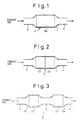
- the reference numeral 1 denotes a catalytic converter accommodating an exhaust gas purifying catalyst 2 applying the method according to the present invention therein.
- An inlet of the catalytic converter 1 is connected to an exhaust duct 3, and the duct 3 is connected to an internal combustion engine.
- An outlet of the catalytic converter 1 is connected to an exhaust duct 4.
- the catalyst 2 comprises a zeolite 2a, as a carrier, carrying both platinum Pt and copper Cu after an ion-changing process, and it is referred as a Pt-Cu zeolite catalyst, hereinafter.
- the Pt-Cu zeolite catalyst 2a is carried on the surface of a substrate in the form of, for example, honeycomb.
- silica rich zeolite may be used, such as ZSM-5 zeolite, ferrierite, mordenite, etc. Note that the Pt-Cu zeolite catalyst 2a is carried substantially over the entire surface of the substrate.
- the exhaust gas purifying catalyst 2 performs the reduction of NO x and the oxidation of NH 3 , when the exhaust gas including NO x and NH 3 contacts the catalyst 2 in an oxidizing atmosphere.
- the exhaust gas including NO x and NH 3 may be an exhaust gas including NO x and NH 3 mixedly, or an exhaust gas having two parts, one including NO x without including NH 3 , the other including NH 3 without including NO x , and the two parts inflowing alternately repeatedly. Also, if the exhaust gas inflowing the exhaust gas purifying catalyst 2 includes both of NO x and NH 3 , NO x oxidizes NH 3 .
- the above purifying mechanism has not been made clear, but it can be considered that the purifying mechanism is performed according to the following reactions (1) to (4), that is: 4NH 3 + 70 2 ⁇ 4NO 2 + 6H 2 O 4NH 3 + 50 2 ⁇ 4NO + 6H 2 O 8NH 3 + 6NO 2 ⁇ 12H 2 O + 7N 2 4NH 3 + 4NO + O 2 ⁇ 6H 2 O + 4N 2
- the reactions (3) and (4) which are denitration reactions, reduce both NO x produced in the oxidation reactions (1) and (2), and NO x flowing into the exhaust gas purifying catalyst 2. In this way, NO x and NH 3 are reduced simultaneously, at the catalyst 2.
- zeolite has an adsorbing and releasing function of NH 3 in which zeolite temporarily adsorbs NH 3 in the inflowing exhaust gas, and releases the adsorbed NH 3 .
- the absorbing and releasing mechanism of NH 3 of zeolite is also unclear but it can be considered that zeolite adsorbs NH 3 when the inflowing exhaust gas includes NH 3 , and releases the adsorbed NH 3 when the concentration of NH 3 in the inflowing exhaust gas becomes lower, or when the inflowing exhaust gas includes NO x .
- the released NH 3 reacts with NO x included in the inflowing exhaust gas to thereby be reduced.
- NH 3 in the inflowing exhaust gas is adsorbed in the catalyst 2 when the exhaust gas part including NH 3 without including NO x contacts with the catalyst 2, and NH 3 in the catalyst 2 is released when the exhaust gas part including NO x without including NH 3 contacts with the catalyst 2.
- the released NH 3 is decomposed by the oxidation reactions (1) and (2) mentioned above, in an oxidizing atmosphere, and NO x in the inflowing exhaust gas is reduced by the denitration reactions (3) and (4) mentioned above.
- the reduction of NO x and NH 3 can be observed when the exhaust gas including NO x and NH 3 contacts, in an oxidizing atmosphere, with a catalyst comprising a zeolite carrying copper Cu by the ion-changing process, which is referred to as the Cu zeolite catalyst, hereinafter.
- the inventors of the present invention have found that it is difficult for the Cu zeolite catalyst to reduce the amounts of NO x and NH 3 sufficiently simultaneously when the temperature of the exhaust gas inflowing the Cu zeolite catalyst is relatively low, for example, at about 100 to 200°C. That is, the large amount of NH 3 is exhausted from the Cu zeolite catalyst without being reduced, although the amount of NO x can be reduced sufficiently. It is considered that this is because the oxidizing ability of copper Cu at the low temperature is relatively weak, and the oxidizing reactions (1) and (2) mentioned above do not occur sufficiently, and thereby NH 3 is not oxidized sufficiently.
- the exhaust gas purifying catalyst 2 is formed as the Pt-Cu zeolite catalyst 2a.
- Platinum Pt has an adequate oxidizing ability even at the low temperature, and thus NH 3 is sufficiently oxidized even when the temperature of the inflowing exhaust gas is relatively low. Accordingly, the amounts of NO x and NH 3 are reduced simultaneously and sufficiently.
- an exhaust gas purifying catalyst 2 consisting of the Pt-Cu zeolite catalyst 2a decompose NH 3 sufficiently at a wider temperature range of the inflowing exhaust gas, for example, about 100 to 500°C, when contacting the exhaust gas including NH 3 without including NO x therewith.
- Fig. 2 shows another embodiment of the exhaust gas purifying catalyst 2 applying the method according to the present invention.
- constituent elements the same as those in Fig. 1 are given the same reference numerals.
- the exhaust gas purifying catalyst 2 comprises the Pt-Cu-zeolite catalyst 2a and the Cu zeolite catalyst 2b. Further, in this embodiment, the Pt-Cu zeolite catalyst 2a and the cu zeolite catalyst 2b are carried on the surface of the common substrate. Namely, the Pt-Cu zeolite catalyst 2a as in the embodiment shown in Fig. 1 is carried on the surface of a downstream portion of the substrate with respect to the exhaust gas flow, and the Cu zeolite catalyst 2b is carried on the surface of an upstream portion of the substrate. Note that the Cu zeolite catalyst 2b is formed of a silica rich zeolite carrying copper Cu after an ion-changing process.
- the exhaust gas purifying catalyst 2 also reduces the amounts of NO x and NH 3 in the exhaust gas simultaneously and sufficiently when contacting the exhaust gas including NO x and NH 3 , in an oxidizing atmosphere.
- the exhaust gas purification based on the purifying mechanism explained by the above mentioned reactions (1) to (4) is performed at each of the Pt-Cu zeolite catalyst 2a and the Cu zeolite catalyst 2b, or over all of the exhaust gas purifying catalyst 2.
- the exhaust gas purifying catalyst 2 reduces the amounts of NO x and NH 3 in the inflowing exhaust gas simultaneously and sufficiently at the low exhaust gas temperature.
- the inventors of the present invention have found that NO x is exhausted from the exhaust gas purifying catalyst 2, without being reduced, when the temperature of the inflowing exhaust gas becomes higher, for example, above about 200°C.
- the exhaust gas purifying catalyst 2 comprises Pt-Cu zeolite catalyst 2a and Cu zeolite catalyst 2b to thereby reduce the amounts of NO x and NH 3 simultaneously and sufficiently at the wider temperature range of the inflowing exhaust gas, that is, for example, about 100 to 500°C. It is considered that this is because the Cu zeolite catalyst 2b, which is arranged upstream of the Pt-Cu zeolite catalyst 2a with respect to the exhaust gas flow, makes the amount of NO x flowing into Pt-Cu zeolite catalyst 2a very small or substantially zero.
- the Pt-Cu zeolite catalyst 2a has a good characteristic for reducing (removing) NH 3 when inflowing the exhaust gas including NH 3 without including NO x as mentioned above, and thus the exhaust gas purifying catalyst 2 has a good exhaust gas purifying characteristic, as a whole.
- the Pt-Cu zeolite catalyst 2a is arranged in the downstream side with respect to the exhaust gas flow, and the Cu zeolite catalyst 2b is arranged in the upstream side.
- the Pt-Cu zeolite catalyst 2a may be arranged in the upstream side, and the Cu zeolite catalyst 2b may be arranged in the downstream side.
- the temperature of the exhaust gas at the downstream side is lower than that at the upstream side. Therefore, arranging the Pt-Cu zeolite catalyst 2a in the downstream side and the Cu zeolite catalyst 2b in the upstream side ensures the sufficient purification of the exhaust gas, while preventing these catalysts 2a and 2b from remarkably deteriorating.
- the Pt-Cu zeolite catalyst 2a can reduce the amount of NH 3 in the exhaust gas including NH 3 without including NO x over the wide temperature range of the inflowing exhaust gas.
- the Pt-Cu zeolite catalyst 2a in the downstream side and the Cu zeolite catalyst 2b in the upstream side, the amounts of NO x and NH 3 are sufficiently reduced in the Pt-Cu zeolite catalyst 2a, even when the temperature of the inflowing exhaust gas is low and thereby NO x and NH 3 are insufficiently reduced in the Cu zeolite catalyst 2b.
- the amount of NH 3 exhausted from the Cu zeolite catalyst 2b is sufficiently reduced in the Pt-Cu zeolite catalyst 2a, because the Pt-Cu zeolite catalyst 2a has good purifying characteristic for reducing (removing) NH 3 .
- the Pt-Cu zeolite catalyst 2a sufficiently reduces the amount of NH 3 exhausted from the Cu zeolite catalyst 2b, even when the concentration of NH 3 in the exhaust gas exhausted from the Cu zeolite catalyst 2b is high. Accordingly, the amount of NO x and NH 3 exhausted from the exhaust gas purifying catalyst 2 without being reduced is extremely reduced.
- Fig. 3 shows the further another embodiment of the exhaust gas purifying catalyst 2 applying the method according to the present invention.
- the exhaust gas purifying catalyst 2 comprises both the Pt-Cu zeolite catalyst 2a and the Cu zeolite catalyst 2b.
- the catalysts 2a and 2b are carried on respective carriers different from each other. That is, the Pt-Cu zeolite catalyst 2a is housed in the catalytic converter 1a arranged on the downstream side, with respect to the exhaust gas flow, and connected to the duct 4, and the Cu zeolite catalyst 2b is housed in the catalytic converter 1b arranged on the upstream side and connected to the duct 3.
- the catalytic converters 1a and 1b are connected to each other via a duct 5.
- the exhaust gas purifying catalyst 2 in this embodiment also reduces the amounts of NO x and NH 3 sufficiently simultaneously.
- the Pt-Cu zeolite catalyst 2a may be on the upstream side and the Cu zeolite catalyst 2b may be on the downstream side, while it is desirable that the Pt-Cu zeolite catalyst 2a is on the downstream side and the Cu zeolite catalyst 2b is on the upstream side.
- Fig. 4 shows still further another embodiment of the exhaust gas purifying catalyst 2 applying the method according to the present invention.
- the exhaust gas purifying catalyst 2 comprises both the Pt-Cu zeolite catalyst 2a and the Cu zeolite catalyst 2b.
- the catalysts 2a and 2b are not arranged in series, but are carried on the common carrier and are laminated thereon to each other. In this case, any laminating order of the catalysts 2a and 2b are acceptable, but it is desirable that the Pt-Cu zeolite catalyst 2a is first carried on the substrate and then the Cu zeolite catalyst 2b is carried thereon to thereby coat the Pt-Cu zeolite catalyst 2a, considering the endurance temperature of the catalysts 2a and 2b. Additionally, the Pt-Cu zeolite catalyst 2a and the Cu zeolite catalyst 2b may be carried on the substrate substantially uniformly.
- Fig. 5 shows the exhaust gas purifying catalyst 2 applying the method of the present invention shown in, for example, Fig. 2, applied to an internal combustion engine.
- the engine 6 is connected to a three-way catalyst 8 as an NH 3 synthesizing catalyst via a duct 7, and the three-way catalyst 8 is connected to the exhaust gas purifying catalyst 2 via the duct 3.
- the engine 6 may be an engine for an automobile.
- the rich engine operation and the lean engine operation are performed alternately and repeatedly.
- the catalyst 8 converts some of the NO x in the exhaust gas to NH 3 , and reduces the remaining NO x to N 2 .
- NH 3 synthesized in the three-way catalyst 8 then flows into the exhaust gas purifying catalyst 2 and is adsorbed therein. Thus, both NO x and NH 3 are prevented from being exhausted from the exhaust gas purifying catalyst 2.
- the exhaust gas exhausted from the engine 6 during the lean engine operation reaches the three-way catalyst 8, NO x in the exhaust gas passes through the catalyst 8 without any oxidation or reduction reactions, and then flows into the exhaust gas catalyst 2.
- the NH 3 concentration in the exhaust gas at this time is substantially zero, and thus NH 3 adsorbed in the exhaust gas purifying catalyst 2 is released.
- the exhaust gas purifying catalyst 2 is in an oxidizing atmosphere, and thus the released NH 3 together with NO x in the inflowing exhaust gas is removed on the exhaust gas purifying catalyst 2. Accordingly, NO x and NH 3 are prevented from being exhausted, from the exhaust gas purifying catalyst 2, when the engine 6 performs the rich engine operation and when the engine 6 performs the lean engine operation.
- the engine 6 may be operated with the stoichiometric air-fuel ratio, in, for example, acceleration.
- the exhaust gas purifying catalyst 2 was prepared to be composed of the Pt-Cu zeolite catalyst 2a carrying 1 wt% platinum Pt and 2.4 wt% copper Cu on the ZSM-5 type zeolite having SiO 2 /Al 2 O 3 (mole ratio) of 40, by an ion-changing process (see Fig. 1).
- the exhaust gas purifying catalyst 2 was prepared to be composed of the Pt-Cu zeolite catalyst 2a as in example 1, and the Cu zeolite catalyst 2b carrying 2.4 wt% copper Cu on the ZSM-5 type zeolite having SiO 2 /Al 2 O 3 (mole ratio) of 40, by an ion-changing process, the Pt-Cu zeolite catalyst 2a being arranged on the downstream portion, with respect to the gas flow, of the exhaust gas purifying catalyst 2, and the Cu zeolite catalyst 2b being arranged on the upstream portion of the exhaust gas purifying catalyst 2 (see Fig. 2).
- the exhaust gas purifying catalyst was prepared to be composed of the Cu zeolite catalyst 2b as in the example 2.
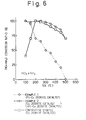
- a model gas simulating the exhaust gas having the following composition was prepared and contacted to the exhaust gas purifying catalysts of the examples 1 and 2 and the comparative example, respectively.
- the conversion ratio of both of NO x and NH 3 was measured at the outlet of the exhaust gas purifying catalyst, at various temperatures of the inflowing gas:
- Fig. 6 shows that the conversion ratio of NO x and NH 3 is maintained above 80%: when the inflowing gas temperature is within the range of about 100 to 180°C, with the example 1; when the inflowing gas temperature is within the range of about 100 to 470°C, with the example 2; and when the inflowing gas temperature is within the range of about 160 to 450°C, with the comparative example. Further, Fig.
- the conversion ratio of NO x and NH 3 is maintained above 90%: when the inflowing gas temperature is within the range of about 100 to 160°C, with the example 1; when the inflowing gas temperature is within the range of about 100 to 400°C, with the example 2; and when the inflowing gas temperature is within the range of about 180 to 350°C, with the comparative example. Accordingly, it can be found that, when the inflowing gas temperature is low, the exhaust gas catalyst of the example 1 reduces the amounts of NO x and NH 3 simultaneously more sufficient than the comparative example. Additionally, the exhaust gas catalyst of the example 2 reduces the amounts of NO x and NH 3 simultaneously more sufficient than the comparative example, over the wider range of the inflowing gas temperature.
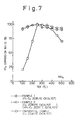
- a model gas simulating the exhaust gas having the following composition was prepared and contacted to the exhaust gas purifying catalysts of the examples 1 and 2 and the comparative example, respectively.
- the conversion ratio of NH 3 was measured at the outlet of the exhaust gas purifying catalyst, at various temperature of the inflowing gas:
- Fig. 7 shows that the conversion ratio of NH 3 is maintained above 80%: when the inflowing gas temperature is within the range of about 100 to 500°C, with the example 1; when the inflowing gas temperature is within the range of about 100 to 500°C, with the example 2; and when the inflowing gas temperature is within the range of about 220 to 450°C, with the comparative example. Further, Fig.
- the exhaust gas purifying catalyst comprises a first catalyst having zeolite carrying platinum and copper thereon.
- the exhaust gas purifying catalyst further comprises a second catalyst having zeolite carrying copper thereon.
- the second catalyst is arranged upstream of the first catalyst, with respect to the exhaust gas flow.
Description
- The present invention relates to a method of purifying an exhaust gas in an internal combustion engine.
- It has been known an exhaust gas purifying apparatus for an internal combustion engine with multi-cylinders, in which an engine air-fuel ratio is controlled to a stoichiometric point, wherein a three-way catalyst is arranged in an exhaust passage connected to each cylinder, to bring nitrogen oxides NOx, hydrocarbon HC, and carbon monoxide CO, which are included in the exhaust gas, into contact with the three-way catalyst, to thereby reduce all components NOx, HC, and CO simultaneously. Note that an air-fuel ratio of an air-fuel mixture in a combustion chamber of an internal combustion engine is referred to as an engine air-fuel ratio, hereinafter.
- On the other hand, a low fuel consumption rate is desirable, and thus it is desirable to make the engine air-fuel ratio as lean as possible. However, if the engine air-fuel ratio is made to be lean with respect to the stoichiometric point, the above-mentioned exhaust gas purifying apparatus cannot reduce NOx sufficiently.
- To solve this problem, Japanese unexamined patent publication No. 4-365920 discloses an exhaust gas purifying apparatus, for an internal combustion engine with multi-cylinders, the engine having a first and a second cylinder groups. The purifying apparatus is provided with: an engine operation control device to continuously make each cylinder of the first cylinder group perform a rich engine operation in which the engine air-fuel ratio is set rich with respect to the stoichiometric point, and to continuously make each cylinder of the second cylinder group perform a lean engine operation, in which the engine air-fuel ratio is set lean with respect to the stoichiometric point; a first exhaust passage connected to each cylinder of the first cylinder group; a second exhaust passage connected to each cylinder of the second cylinder group and different from the first exhaust passage; an ammonia synthesizing catalyst arranged in the first exhaust passage for synthesizing ammonia NH3 from NOx in the inflowing exhaust gas; an interconnecting passage interconnecting the first exhaust passage downstream of the NH3 synthesizing catalyst and the second exhaust passage to each other; and an exhaust gas purifying catalyst arranged in the interconnecting passage to react NOx and NH3 inflowing therein with each other to thereby reduce NOx and NH3 simultaneously. In this exhaust gas purifying apparatus, the fuel consumption rate is reduced by increasing the numbers of the cylinders of the second cylinder group in which the lean engine operation is performed, while NOx is sufficiently reduced by introducing the exhaust gas from the first cylinder group in which the rich engine operation is performed to thereby synthesize NH3, and by reacting this NH3 and NOx from the second cylinder group at the exhaust gas purifying catalyst.
- The exhaust gas purifying catalyst may be a catalyst having a zeolite carrying cobalt Co, copper Cu, Nickel Ni, or iron Fe. However, the inventors of the present application have found that such a catalyst sufficiently reduces NOx and NH3 simultaneously only when the temperature of the exhaust gas entering therein is within a specific temperature range, which is referred as a purifying temperature range hereinafter. In the actual engine operation, however, the inflowing exhaust gas temperature varies outside the purifying temperature range. When the inflowing exhaust gas temperature is out of the purifying temperature range, the above catalyst would not reduce NOx and NH3 simultaneously sufficiently. An additional device to cool or heat the exhaust gas inflowing the catalyst may keep the inflowing gas temperature within the purifying temperature range, but such an additional device may complicate the arrangement of the purifying apparatus, and may be costly.
- US-A-5,409,671 discloses a catalytic convertor for treating exhaust gas including a first catalyst layer formed on a base material and a second catalyst layer formed on the first catalyst layer. The first catalyst layer is composed of metal-containing silicate provided with transition metal by ion exchange and at least one noble metal on the silicate and the second catalyst layer is composed of metal-containing silicate provided with transition metal by ion exchange and at least one metal on the silicate. By such a catalytic convertor, the NOx treating efficiency at low temperatures is improved.
- On the other hand, JP-A-6-190 246 identified by its English abstract discloses an apparatus for cleaning exhaust gas of a car having a first honeycomb catalyst based on a zeolite containing copper and phosphorus and a second honeycomb catalyst based on alumino silicate (zeolite) containing a noble metal. The first catalyst may optionally contain a noble metal such as platinum which may also be the noble metal of the second catalyst. Such an apparatus is useful for purifying an exhaust gas from hydrocarbons and nitrogen oxides in a wide range of stoichiometric oxygen content and lean atmosphere.
- Further exhaust gas purifying catalysts comprising zeolites as the active species are disclosed in JP-A-5-228 342 and JP-A-7-232 035. These catalysts show an improved NOx purifying efficiency.
- An object of the present invention is to provide an exhaust gas purifying catalyst for reducing the amounts of nitrogen oxides and ammonia in an exhaust gas and sufficiently simultaneously, with a wider purifying temperature range.
- According to the present invention, there is provided a method of purifying an exhaust gas of an internal combustion engine, comprising providing an exhaust gas purifying catalyst comprising a first catalyst having zeolite carrying platinum and copper thereon introducing the exhaust gas including nitrogen oxide and ammonia into said first catalyst in an oxidizing atmosphere to simultaneously remove nitrogen oxides and ammonia in the exhaust gas under an oxidizing atmosphere.
- The present invention may be more fully understood from the description of preferred embodiments of the invention set forth below, together with the accompanying drawings.
- In the drawings:
- Fig. 1 shows a first embodiment of an exhaust gas purifying catalyst applying the method according to the present invention;
- Fig. 2 shows a second embodiment of an exhaust gas purifying catalyst applying the method according to the present invention;
- Fig. 3 shows a third embodiment of an exhaust gas purifying catalyst applying the method according to the present invention;
- Fig. 4 shows a fourth embodiment of an exhaust gas purifying catalyst applying the method according to the present invention;
- Fig. 5 is a general view of an internal combustion engine provided with an exhaust gas purifying catalyst applying the method according to the present invention;
- Fig. 6 is a diagram representing experimental results of an NOx and NH3 conversion ratio; and
- Fig. 7 is a diagram representing experimental results of an NOx conversion ratio.
-
- In general, nitrogen oxides NOx include nitrogen monoxide NO, nitrogen dioxide NO2, dinitrogen tetroxide N2O4, dinitrogen monoxide N2O, etc. The following explanation is made by considering NOx to-mainly consist of nitrogen monoxide NO and/or nitrogen dioxide NO2, but an exhaust gas purifying catalyst according to the present invention can reduce other nitrogen oxides.
- Referring to Fig. 1, the
reference numeral 1 denotes a catalytic converter accommodating an exhaust gas purifyingcatalyst 2 applying the method according to the present invention therein. An inlet of thecatalytic converter 1 is connected to anexhaust duct 3, and theduct 3 is connected to an internal combustion engine. An outlet of thecatalytic converter 1 is connected to anexhaust duct 4. - In the embodiment shown in Fig. 1, the
catalyst 2 comprises azeolite 2a, as a carrier, carrying both platinum Pt and copper Cu after an ion-changing process, and it is referred as a Pt-Cu zeolite catalyst, hereinafter. The Pt-Cu zeolite catalyst 2a is carried on the surface of a substrate in the form of, for example, honeycomb. For zeolite, silica rich zeolite may be used, such as ZSM-5 zeolite, ferrierite, mordenite, etc. Note that the Pt-Cu zeolite catalyst 2a is carried substantially over the entire surface of the substrate. - The exhaust gas purifying
catalyst 2 performs the reduction of NOx and the oxidation of NH3, when the exhaust gas including NOx and NH3 contacts thecatalyst 2 in an oxidizing atmosphere. In this case, the exhaust gas including NOx and NH3 may be an exhaust gas including NOx and NH3 mixedly, or an exhaust gas having two parts, one including NOx without including NH3, the other including NH3 without including NOx, and the two parts inflowing alternately repeatedly. Also, if the exhaust gas inflowing the exhaust gas purifyingcatalyst 2 includes both of NOx and NH3, NOx oxidizes NH3. The above purifying mechanism has not been made clear, but it can be considered that the purifying mechanism is performed according to the following reactions (1) to (4), that is:catalyst 2. In this way, NOx and NH3 are reduced simultaneously, at thecatalyst 2. - Note that zeolite has an adsorbing and releasing function of NH3 in which zeolite temporarily adsorbs NH3 in the inflowing exhaust gas, and releases the adsorbed NH3. The absorbing and releasing mechanism of NH3 of zeolite is also unclear but it can be considered that zeolite adsorbs NH3 when the inflowing exhaust gas includes NH3, and releases the adsorbed NH3 when the concentration of NH3 in the inflowing exhaust gas becomes lower, or when the inflowing exhaust gas includes NOx. The released NH3 reacts with NOx included in the inflowing exhaust gas to thereby be reduced. Accordingly, if the exhaust gas part including NOx without including NH3, and the exhaust gas part including NH3 without including NOx contact with the exhaust gas purifying
catalyst 2 alternately repeatedly, NH3 in the inflowing exhaust gas is adsorbed in thecatalyst 2 when the exhaust gas part including NH3 without including NOx contacts with thecatalyst 2, and NH3 in thecatalyst 2 is released when the exhaust gas part including NOx without including NH3 contacts with thecatalyst 2. The released NH3 is decomposed by the oxidation reactions (1) and (2) mentioned above, in an oxidizing atmosphere, and NOx in the inflowing exhaust gas is reduced by the denitration reactions (3) and (4) mentioned above. - On the other hand, the reduction of NOx and NH3 can be observed when the exhaust gas including NOx and NH3 contacts, in an oxidizing atmosphere, with a catalyst comprising a zeolite carrying copper Cu by the ion-changing process, which is referred to as the Cu zeolite catalyst, hereinafter. However, the inventors of the present invention have found that it is difficult for the Cu zeolite catalyst to reduce the amounts of NOx and NH3 sufficiently simultaneously when the temperature of the exhaust gas inflowing the Cu zeolite catalyst is relatively low, for example, at about 100 to 200°C. That is, the large amount of NH3 is exhausted from the Cu zeolite catalyst without being reduced, although the amount of NOx can be reduced sufficiently. It is considered that this is because the oxidizing ability of copper Cu at the low temperature is relatively weak, and the oxidizing reactions (1) and (2) mentioned above do not occur sufficiently, and thereby NH3 is not oxidized sufficiently.
- In this embodiment, the exhaust gas purifying
catalyst 2 is formed as the Pt-Cu zeolite catalyst 2a. Platinum Pt has an adequate oxidizing ability even at the low temperature, and thus NH3 is sufficiently oxidized even when the temperature of the inflowing exhaust gas is relatively low. Accordingly, the amounts of NOx and NH3 are reduced simultaneously and sufficiently. - Note that the inventors of the present invention have found that an exhaust
gas purifying catalyst 2 consisting of the Pt-Cu zeolite catalyst 2a decompose NH3 sufficiently at a wider temperature range of the inflowing exhaust gas, for example, about 100 to 500°C, when contacting the exhaust gas including NH3 without including NOx therewith. - Fig. 2 shows another embodiment of the exhaust
gas purifying catalyst 2 applying the method according to the present invention. In Fig. 2, constituent elements the same as those in Fig. 1 are given the same reference numerals. - In the embodiment shown in Fig. 2, the exhaust
gas purifying catalyst 2 comprises the Pt-Cu-zeolite catalyst 2a and theCu zeolite catalyst 2b. Further, in this embodiment, the Pt-Cu zeolite catalyst 2a and thecu zeolite catalyst 2b are carried on the surface of the common substrate. Namely, the Pt-Cu zeolite catalyst 2a as in the embodiment shown in Fig. 1 is carried on the surface of a downstream portion of the substrate with respect to the exhaust gas flow, and theCu zeolite catalyst 2b is carried on the surface of an upstream portion of the substrate. Note that theCu zeolite catalyst 2b is formed of a silica rich zeolite carrying copper Cu after an ion-changing process. - The exhaust
gas purifying catalyst 2 according to this embodiment also reduces the amounts of NOx and NH3 in the exhaust gas simultaneously and sufficiently when contacting the exhaust gas including NOx and NH3, in an oxidizing atmosphere. In this embodiment, it is considered that the exhaust gas purification based on the purifying mechanism explained by the above mentioned reactions (1) to (4) is performed at each of the Pt-Cu zeolite catalyst 2a and theCu zeolite catalyst 2b, or over all of the exhaustgas purifying catalyst 2. - As mentioned above, if the exhaust
gas purifying catalyst 2 is formed as the Pt-Cu zeolite catalyst 2a, the exhaustgas purifying catalyst 2 reduces the amounts of NOx and NH3 in the inflowing exhaust gas simultaneously and sufficiently at the low exhaust gas temperature. However, the inventors of the present invention have found that NOx is exhausted from the exhaustgas purifying catalyst 2, without being reduced, when the temperature of the inflowing exhaust gas becomes higher, for example, above about 200°C. It is considered that this is because, when the temperature of the inflowing exhaust gas becomes higher, the oxidizing ability of platinum Pt becomes too strong, and a very large amount of NOx is synthesized by the oxidizing reactions (1) and (2) mentioned above, and thus it becomes-difficult for the denitration reactions (3) and (4) mentioned above to reduce NOx sufficiently. - In this embodiment, the exhaust
gas purifying catalyst 2 comprises Pt-Cu zeolite catalyst 2a andCu zeolite catalyst 2b to thereby reduce the amounts of NOx and NH3 simultaneously and sufficiently at the wider temperature range of the inflowing exhaust gas, that is, for example, about 100 to 500°C. It is considered that this is because theCu zeolite catalyst 2b, which is arranged upstream of the Pt-Cu zeolite catalyst 2a with respect to the exhaust gas flow, makes the amount of NOx flowing into Pt-Cu zeolite catalyst 2a very small or substantially zero. That is, the Pt-Cu zeolite catalyst 2a has a good characteristic for reducing (removing) NH3 when inflowing the exhaust gas including NH3 without including NOx as mentioned above, and thus the exhaustgas purifying catalyst 2 has a good exhaust gas purifying characteristic, as a whole. - Referring to Fig. 2 again, the Pt-
Cu zeolite catalyst 2a is arranged in the downstream side with respect to the exhaust gas flow, and theCu zeolite catalyst 2b is arranged in the upstream side. Alternatively, the Pt-Cu zeolite catalyst 2a may be arranged in the upstream side, and theCu zeolite catalyst 2b may be arranged in the downstream side. However, it is desired that the Pt-Cu zeolite catalyst 2a is arranged in the downstream side, and theCu zeolite catalyst 2b is arranged in the upstream side, as shown in Fig. 2. It has been found that the endurance temperature and the working temperature of the Pt-Cu zeolite catalyst 2a are lower than those of theCu zeolite catalyst 2b respectively. And, generally, the temperature of the exhaust gas at the downstream side is lower than that at the upstream side. Therefore, arranging the Pt-Cu zeolite catalyst 2a in the downstream side and theCu zeolite catalyst 2b in the upstream side ensures the sufficient purification of the exhaust gas, while preventing thesecatalysts - Further, as mentioned above, the Pt-
Cu zeolite catalyst 2a can reduce the amount of NH3 in the exhaust gas including NH3 without including NOx over the wide temperature range of the inflowing exhaust gas. Thus, by arranging the Pt-Cu zeolite catalyst 2a in the downstream side and theCu zeolite catalyst 2b in the upstream side, the amounts of NOx and NH3 are sufficiently reduced in the Pt-Cu zeolite catalyst 2a, even when the temperature of the inflowing exhaust gas is low and thereby NOx and NH3 are insufficiently reduced in theCu zeolite catalyst 2b. - Further, even when NH3 passes through the
Cu zeolite catalyst 2b without being reduced by greatly increasing the NH3 amount flowing into the exhaustgas purifying catalyst 2 or the NH3 amount exhausted from theCu zeolite catalyst 2b, the amount of NH3 exhausted from theCu zeolite catalyst 2b is sufficiently reduced in the Pt-Cu zeolite catalyst 2a, because the Pt-Cu zeolite catalyst 2a has good purifying characteristic for reducing (removing) NH3. Namely, the Pt-Cu zeolite catalyst 2a sufficiently reduces the amount of NH3 exhausted from theCu zeolite catalyst 2b, even when the concentration of NH3 in the exhaust gas exhausted from theCu zeolite catalyst 2b is high. Accordingly, the amount of NOx and NH3 exhausted from the exhaustgas purifying catalyst 2 without being reduced is extremely reduced. - Fig. 3 shows the further another embodiment of the exhaust
gas purifying catalyst 2 applying the method according to the present invention. Also, in this embodiment, the exhaustgas purifying catalyst 2 comprises both the Pt-Cu zeolite catalyst 2a and theCu zeolite catalyst 2b. However, thecatalysts Cu zeolite catalyst 2a is housed in thecatalytic converter 1a arranged on the downstream side, with respect to the exhaust gas flow, and connected to theduct 4, and theCu zeolite catalyst 2b is housed in the catalytic converter 1b arranged on the upstream side and connected to theduct 3. Thecatalytic converters 1a and 1b are connected to each other via aduct 5. - The exhaust
gas purifying catalyst 2 in this embodiment also reduces the amounts of NOx and NH3 sufficiently simultaneously. Further, the Pt-Cu zeolite catalyst 2a may be on the upstream side and theCu zeolite catalyst 2b may be on the downstream side, while it is desirable that the Pt-Cu zeolite catalyst 2a is on the downstream side and theCu zeolite catalyst 2b is on the upstream side. - Fig. 4 shows still further another embodiment of the exhaust
gas purifying catalyst 2 applying the method according to the present invention. Also, in this embodiment, the exhaustgas purifying catalyst 2 comprises both the Pt-Cu zeolite catalyst 2a and theCu zeolite catalyst 2b. However, thecatalysts catalysts Cu zeolite catalyst 2a is first carried on the substrate and then theCu zeolite catalyst 2b is carried thereon to thereby coat the Pt-Cu zeolite catalyst 2a, considering the endurance temperature of thecatalysts Cu zeolite catalyst 2a and theCu zeolite catalyst 2b may be carried on the substrate substantially uniformly. - Fig. 5 shows the exhaust
gas purifying catalyst 2 applying the method of the present invention shown in, for example, Fig. 2, applied to an internal combustion engine. Referring to Fig. 5, theengine 6 is connected to a three-way catalyst 8 as an NH3 synthesizing catalyst via aduct 7, and the three-way catalyst 8 is connected to the exhaustgas purifying catalyst 2 via theduct 3. Theengine 6 may be an engine for an automobile. - In the
engine 6, the rich engine operation and the lean engine operation are performed alternately and repeatedly. When the exhaust gas exhausted from theengine 6 during the rich engine operation thereof reaches the three-way catalyst 8, thecatalyst 8 converts some of the NOx in the exhaust gas to NH3, and reduces the remaining NOx to N2. NH3 synthesized in the three-way catalyst 8 then flows into the exhaustgas purifying catalyst 2 and is adsorbed therein. Thus, both NOx and NH3 are prevented from being exhausted from the exhaustgas purifying catalyst 2. - On the other hand, the exhaust gas exhausted from the
engine 6 during the lean engine operation reaches the three-way catalyst 8, NOx in the exhaust gas passes through thecatalyst 8 without any oxidation or reduction reactions, and then flows into theexhaust gas catalyst 2. The NH3 concentration in the exhaust gas at this time is substantially zero, and thus NH3 adsorbed in the exhaustgas purifying catalyst 2 is released. At this time, the exhaustgas purifying catalyst 2 is in an oxidizing atmosphere, and thus the released NH3 together with NOx in the inflowing exhaust gas is removed on the exhaustgas purifying catalyst 2. Accordingly, NOx and NH3 are prevented from being exhausted, from the exhaustgas purifying catalyst 2, when theengine 6 performs the rich engine operation and when theengine 6 performs the lean engine operation. Note that theengine 6 may be operated with the stoichiometric air-fuel ratio, in, for example, acceleration. - The exhaust
gas purifying catalyst 2 was prepared to be composed of the Pt-Cu zeolite catalyst 2a carrying 1 wt% platinum Pt and 2.4 wt% copper Cu on the ZSM-5 type zeolite having SiO2/Al2O3 (mole ratio) of 40, by an ion-changing process (see Fig. 1). - The exhaust
gas purifying catalyst 2 was prepared to be composed of the Pt-Cu zeolite catalyst 2a as in example 1, and theCu zeolite catalyst 2b carrying 2.4 wt% copper Cu on the ZSM-5 type zeolite having SiO2/Al2O3 (mole ratio) of 40, by an ion-changing process, the Pt-Cu zeolite catalyst 2a being arranged on the downstream portion, with respect to the gas flow, of the exhaustgas purifying catalyst 2, and theCu zeolite catalyst 2b being arranged on the upstream portion of the exhaust gas purifying catalyst 2 (see Fig. 2). - The exhaust gas purifying catalyst was prepared to be composed of the
Cu zeolite catalyst 2b as in the example 2. - A model gas simulating the exhaust gas having the following composition was prepared and contacted to the exhaust gas purifying catalysts of the examples 1 and 2 and the comparative example, respectively. The conversion ratio of both of NOx and NH3 was measured at the outlet of the exhaust gas purifying catalyst, at various temperatures of the inflowing gas:
- NH3:
- 100 (ppm)
- NOx:
- 100 (ppm)
- CO2:
- 15(%)
- O2:
- 4(%)
- H2O:
- 3(%)
- N2:
- balance
- The experimental results are shown in Fig. 6. Fig. 6 shows that the conversion ratio of NOx and NH3 is maintained above 80%: when the inflowing gas temperature is within the range of about 100 to 180°C, with the example 1; when the inflowing gas temperature is within the range of about 100 to 470°C, with the example 2; and when the inflowing gas temperature is within the range of about 160 to 450°C, with the comparative example. Further, Fig. 6 shows that the conversion ratio of NOx and NH3 is maintained above 90%: when the inflowing gas temperature is within the range of about 100 to 160°C, with the example 1; when the inflowing gas temperature is within the range of about 100 to 400°C, with the example 2; and when the inflowing gas temperature is within the range of about 180 to 350°C, with the comparative example. Accordingly, it can be found that, when the inflowing gas temperature is low, the exhaust gas catalyst of the example 1 reduces the amounts of NOx and NH3 simultaneously more sufficient than the comparative example. Additionally, the exhaust gas catalyst of the example 2 reduces the amounts of NOx and NH3 simultaneously more sufficient than the comparative example, over the wider range of the inflowing gas temperature.
- A model gas simulating the exhaust gas having the following composition was prepared and contacted to the exhaust gas purifying catalysts of the examples 1 and 2 and the comparative example, respectively. The conversion ratio of NH3 was measured at the outlet of the exhaust gas purifying catalyst, at various temperature of the inflowing gas:
- NH3:
- 100 (ppm)
- CO2:
- 15(%)
- O2:
- 4(%)
- H2O:
- 3(%)
- N2:
- balance
- The experimental results are shown in Fig. 7. Fig. 7 shows that the conversion ratio of NH3 is maintained above 80%: when the inflowing gas temperature is within the range of about 100 to 500°C, with the example 1; when the inflowing gas temperature is within the range of about 100 to 500°C, with the example 2; and when the inflowing gas temperature is within the range of about 220 to 450°C, with the comparative example. Further, Fig. 7 shows that the conversion ratio of NH3 is maintained above 90%: when the inflowing gas temperature is within the range of about 100 to 500°C, with the example 1; when the inflowing gas temperature is within the range of about 100 to 500°C, with the example 2; and when the inflowing gas temperature is within the range of about 240 to 400°C, with the comparative example. Accordingly, it can be seen that the exhaust gas catalyst of the examples 1 and 2 reduce NH3 more sufficient than the comparative example, over the wider range of the inflowing gas temperature.
- According to the present invention, it is possible to provide a method of purifying an exhaust gas for reducing nitrogen oxides and ammonia in an exhaust gas sufficiently simultaneously, with a wider purifying temperature range.
- While the invention has been described by reference to specific embodiments chosen for purposes of illustration, it should be apparent that numerous modifications could be made thereto by those skilled in the art without departing from the basic concept and scope of the invention.
- An method of purifying an exhaust gas by means of an exhaust gas purifying catalyst for simultaneously reducing nitrogen oxides and ammonia in an exhaust gas of an internal combustion engine, in an oxidizing atmosphere, is provided. The exhaust gas purifying catalyst comprises a first catalyst having zeolite carrying platinum and copper thereon. Preferably, the exhaust gas purifying catalyst further comprises a second catalyst having zeolite carrying copper thereon. Preferably, the second catalyst is arranged upstream of the first catalyst, with respect to the exhaust gas flow.
Claims (10)
- A method of purifying an exhaust gas of an internal combustion engine, comprising
providing an exhaust gas purifying catalyst comprising a first catalyst having zeolite carrying platinum and copper thereon,
introducing the exhaust gas including nitrogen oxide and ammonia into said first catalyst in an oxidizing atmosphere; and
simultaneously removing from said exhaust gas nitrogen oxide and ammonia in an oxidizing atmosphere. - The method according to claim 1, further comprising the provision of a second catalyst having zeolite carrying copper thereon.
- The method according to claim 2, wherein the first and second catalysts are arranged in series along the flow direction of the exhaust gas.
- The method according to claim 3, wherein the first catalyst is arranged downstream of the second catalyst along the flow direction of the exhaust gas.
- The method according to claim 3, wherein the first and second catalysts are carried on a common substrate.
- The method according to claim 2, wherein the first and second catalysts are carried on a common substrate.
- The method according to claim 6, wherein the first and second catalysts are disposed on each other to form a laminated catalyst.
- The method according to claim 7, wherein the first catalyst is carried on the substrate, and the second catalyst is disposed on the first catalyst.
- The method according to claim 2, wherein each of the first and second catalysts is carried on an individual substrate.
- The method according to claim 1 or 2, wherein said zeolite is silica-rich zeolite.
Applications Claiming Priority (9)
| Application Number | Priority Date | Filing Date | Title |
|---|---|---|---|
| JP29125895 | 1995-11-09 | ||
| JP291258/95 | 1995-11-09 | ||
| JP29125895 | 1995-11-09 | ||
| JP30153095 | 1995-11-20 | ||
| JP301530/95 | 1995-11-20 | ||
| JP30153095 | 1995-11-20 | ||
| JP32029995 | 1995-12-08 | ||
| JP320299/95 | 1995-12-08 | ||
| JP32029995A JP3499350B2 (en) | 1995-12-08 | 1995-12-08 | Exhaust gas purification method for internal combustion engine |
Publications (2)
| Publication Number | Publication Date |
|---|---|
| EP0773057A1 EP0773057A1 (en) | 1997-05-14 |
| EP0773057B1 true EP0773057B1 (en) | 2002-08-28 |
Family
ID=27337639
Family Applications (1)
| Application Number | Title | Priority Date | Filing Date |
|---|---|---|---|
| EP96117850A Expired - Lifetime EP0773057B1 (en) | 1995-11-09 | 1996-11-07 | Exhaust gas purifying catalyst |
Country Status (3)
| Country | Link |
|---|---|
| US (1) | US6133185A (en) |
| EP (1) | EP0773057B1 (en) |
| DE (1) | DE69623232T2 (en) |
Cited By (1)
| Publication number | Priority date | Publication date | Assignee | Title |
|---|---|---|---|---|
| US11845067B2 (en) | 2007-02-27 | 2023-12-19 | Basf Corporation | Copper CHA zeolite catalysts |
Families Citing this family (45)
| Publication number | Priority date | Publication date | Assignee | Title |
|---|---|---|---|---|
| JP2000356125A (en) * | 1999-06-14 | 2000-12-26 | Honda Motor Co Ltd | Exhaust emission control device for internal combustion engine |
| JP4568991B2 (en) * | 2000-02-23 | 2010-10-27 | マツダ株式会社 | Engine exhaust purification device and fuel injection timing setting method |
| JP3871501B2 (en) * | 2000-08-07 | 2007-01-24 | 株式会社ノリタケカンパニーリミテド | Zeolite membrane, production method thereof and membrane reactor |
| JP2002263501A (en) * | 2001-03-05 | 2002-09-17 | Toyota Motor Corp | Carbon monoxide selective oxidizing catalyst and method for manufacturing the same |
| GB2376903A (en) * | 2001-04-05 | 2002-12-31 | Johnson Matthey Plc | Nitrogen oxides emission control under lean-burn conditions |
| US7552583B2 (en) * | 2004-11-08 | 2009-06-30 | Caterpillar Inc. | Exhaust purification with on-board ammonia production |
| US7332135B2 (en) * | 2002-10-22 | 2008-02-19 | Ford Global Technologies, Llc | Catalyst system for the reduction of NOx and NH3 emissions |
| WO2005018807A1 (en) * | 2003-08-26 | 2005-03-03 | Sued-Chemie Catalysts Japan, Inc. | Ammonia decomposition catalyst and method of decomposing ammonia with the catalyst |
| DE10360955A1 (en) * | 2003-12-23 | 2005-07-21 | Umicore Ag & Co. Kg | Emission control system and method for removing nitrogen oxides from the exhaust gas of internal combustion engines with the aid of catalytically generated ammonia |
| DE102004058210A1 (en) * | 2004-12-02 | 2006-06-14 | Hte Ag The High Throughput Experimentation Company | Integrated catalyst system to remove e.g. nitric oxides from exhaust gases comprises nitric oxide storing component, ammonia-generating component, ammonia-storing component and selective catalytic reduction component on common substrate |
| JP4733110B2 (en) * | 2004-04-16 | 2011-07-27 | ハーテーエー・アクチェンゲゼルシャフト・ザ・ハイ・スループット・イクスペリメンテイション・カンパニー | Method for removing harmful substances from exhaust gas of combustion engine and catalyst for carrying out the method |
| US20070227143A1 (en) * | 2004-11-08 | 2007-10-04 | Robel Wade J | Exhaust purification with on-board ammonia production |
| JP4907860B2 (en) * | 2004-11-11 | 2012-04-04 | 株式会社キャタラー | Filter catalyst |
| EP1872852A1 (en) * | 2005-03-30 | 2008-01-02 | Sued-Chemie Catalysts Japan, Inc. | Ammonia decomposition catalyst and process for decomposition of ammonia using the catalyst |
| KR100765413B1 (en) * | 2005-07-06 | 2007-10-09 | 희성촉매 주식회사 | An oxidation catalyst for NH3 and an apparatus for treating slipped or scrippedd NH3 |
| WO2007004774A1 (en) * | 2005-07-06 | 2007-01-11 | Heesung Catalysts Corporation | An oxidation catalyst for nh3 and an apparatus for treating slipped or scrippedd nh3 |
| US7811536B2 (en) * | 2005-07-21 | 2010-10-12 | University Of Delaware | Nitrogen oxides storage catalysts containing cobalt |
| US7371353B2 (en) * | 2005-08-31 | 2008-05-13 | Caterpillar Inc. | Exhaust purification with on-board ammonia production |
| US7485272B2 (en) * | 2005-11-30 | 2009-02-03 | Caterpillar Inc. | Multi-stage system for selective catalytic reduction |
| US7805929B2 (en) * | 2005-12-21 | 2010-10-05 | Caterpillar Inc | Selective catalytic reduction system |
| US20100166628A1 (en) * | 2006-02-15 | 2010-07-01 | Nicola Soeger | Catalyst for reducing nitrogen-containing pollutants from the exhaust gases of diesel engines |
| US7490462B2 (en) * | 2006-02-21 | 2009-02-17 | Caterpillar Inc. | Turbocharged exhaust gas recirculation system |
| US20080022666A1 (en) * | 2006-07-31 | 2008-01-31 | Driscoll James J | Balanced partial two-stroke engine |
| WO2008106523A2 (en) * | 2007-02-27 | 2008-09-04 | Basf Catalysts Llc | Bifunctional catalysts for selective ammonia oxidation |
| CN101668589B (en) | 2007-02-27 | 2013-06-12 | 巴斯福催化剂公司 | Copper CHA zeolite catalysts |
| JP5777339B2 (en) | 2007-04-26 | 2015-09-09 | ジョンソン、マッセイ、パブリック、リミテッド、カンパニーJohnson Matthey Publiclimited Company | Transition metal / zeolite SCR catalyst |
| US20090196812A1 (en) | 2008-01-31 | 2009-08-06 | Basf Catalysts Llc | Catalysts, Systems and Methods Utilizing Non-Zeolitic Metal-Containing Molecular Sieves Having the CHA Crystal Structure |
| DE102008010330A1 (en) * | 2008-02-21 | 2009-09-03 | Süd-Chemie AG | SCR catalytic converter with ammonia storage function |
| WO2009141895A1 (en) * | 2008-05-20 | 2009-11-26 | イビデン株式会社 | Exhaust gas purification apparatus |
| US20100050604A1 (en) * | 2008-08-28 | 2010-03-04 | John William Hoard | SCR-LNT CATALYST COMBINATION FOR IMPROVED NOx CONTROL OF LEAN GASOLINE AND DIESEL ENGINES |
| US8225597B2 (en) * | 2008-09-30 | 2012-07-24 | Ford Global Technologies, Llc | System for reducing NOx in exhaust |
| US8343448B2 (en) * | 2008-09-30 | 2013-01-01 | Ford Global Technologies, Llc | System for reducing NOx in exhaust |
| US8524185B2 (en) * | 2008-11-03 | 2013-09-03 | Basf Corporation | Integrated SCR and AMOx catalyst systems |
| US10632423B2 (en) * | 2008-11-03 | 2020-04-28 | Basf Corporation | Bimetallic catalysts for selective ammonia oxidation |
| US10583424B2 (en) | 2008-11-06 | 2020-03-10 | Basf Corporation | Chabazite zeolite catalysts having low silica to alumina ratios |
| US8844274B2 (en) * | 2009-01-09 | 2014-09-30 | Ford Global Technologies, Llc | Compact diesel engine exhaust treatment system |
| US8062618B2 (en) * | 2009-04-17 | 2011-11-22 | Ford Global Technologies, Llc | Exhaust aftertreatment system and method of treating exhaust gas |
| US8293198B2 (en) | 2009-12-18 | 2012-10-23 | Basf Corporation | Process of direct copper exchange into Na+-form of chabazite molecular sieve, and catalysts, systems and methods |
| US8293199B2 (en) | 2009-12-18 | 2012-10-23 | Basf Corporation | Process for preparation of copper containing molecular sieves with the CHA structure, catalysts, systems and methods |
| US8293182B2 (en) | 2010-05-05 | 2012-10-23 | Basf Corporation | Integrated SCR and AMOx catalyst systems |
| US9441517B2 (en) * | 2010-09-02 | 2016-09-13 | Ford Global Technologies, Llc | Diesel engine exhaust treatment system |
| US8137648B2 (en) * | 2010-10-12 | 2012-03-20 | Ford Global Technologies, Llc | Diesel engine exhaust treatment system and method including a platinum group metal trapping device |
| CN104114276B (en) * | 2012-02-15 | 2017-04-12 | 丰田自动车株式会社 | Catalyst system for exhaust gas purification utilizing base metals, and controlling method thereof |
| CN107847918A (en) * | 2015-06-18 | 2018-03-27 | 庄信万丰股份有限公司 | Individual layer or double-deck NH_3 leakage catalyst |
| EP3600624A1 (en) * | 2017-03-29 | 2020-02-05 | Johnson Matthey Public Limited Company | Asc with platinum group metal in multiple layers |
Family Cites Families (25)
| Publication number | Priority date | Publication date | Assignee | Title |
|---|---|---|---|---|
| GB1362202A (en) * | 1971-01-19 | 1974-07-30 | British Leyland Motor Corp | Exhaust systems for internal combustion engines |
| US3825654A (en) * | 1972-04-21 | 1974-07-23 | Gulf Research Development Co | Process for reducing the content of nitrogen oxides in the exhaust gases from internal combustion engines |
| US3953576A (en) * | 1974-02-13 | 1976-04-27 | Standard Oil Company | Maximizing conversion of nitrogen oxides in the treatment of combustion exhaust gases |
| US4393031A (en) * | 1979-02-22 | 1983-07-12 | Werner Henke | Process for efficiently removing oxides of nitrogen from exhaust gas |
| FR2450946A1 (en) * | 1979-03-08 | 1980-10-03 | Peugeot | DEVICE FOR PURIFYING EXHAUST GASES FROM AN EXPLOSION ENGINE |
| US4395875A (en) * | 1981-07-24 | 1983-08-02 | Texaco Inc. | Method for rejuvenating an exhaust gas filter for a diesel engine |
| JP2748686B2 (en) * | 1990-11-16 | 1998-05-13 | トヨタ自動車株式会社 | In-cylinder direct injection spark ignition engine |
| AU645632B2 (en) * | 1990-12-06 | 1994-01-20 | Tosoh Corporation | Catalyst for purifying exhaust gas |
| US5410873A (en) * | 1991-06-03 | 1995-05-02 | Isuzu Motors Limited | Apparatus for diminishing nitrogen oxides |
| JP2967113B2 (en) | 1991-06-12 | 1999-10-25 | 株式会社豊田中央研究所 | Exhaust gas purification method |
| JP3086015B2 (en) * | 1991-08-07 | 2000-09-11 | トヨタ自動車株式会社 | Exhaust gas purification catalyst |
| JP2800499B2 (en) * | 1991-09-18 | 1998-09-21 | 日産自動車株式会社 | Hydrocarbon adsorbent |
| JP3098083B2 (en) * | 1991-12-26 | 2000-10-10 | マツダ株式会社 | Exhaust gas purification catalyst |
| JPH05228342A (en) * | 1992-02-20 | 1993-09-07 | Mazda Motor Corp | Purifier for exhaust gas |
| JPH06190246A (en) * | 1992-12-25 | 1994-07-12 | Idemitsu Kosan Co Ltd | Exhaust gas purifying device for automobile |
| EP0621400B1 (en) * | 1993-04-23 | 1999-03-31 | Daimler-Benz Aktiengesellschaft | Air compressing injection internal combustion engine with an exhaust gas treating device for reducing nitrous oxides |
| JP3246086B2 (en) * | 1993-06-11 | 2002-01-15 | トヨタ自動車株式会社 | Exhaust gas purification device for internal combustion engine |
| JPH07232035A (en) * | 1994-02-21 | 1995-09-05 | Toray Ind Inc | Method and apparatus for purifying nitrogen oxide |
| JP3427581B2 (en) * | 1994-09-13 | 2003-07-22 | トヨタ自動車株式会社 | Exhaust gas purification device for internal combustion engine |
| JP3440654B2 (en) * | 1994-11-25 | 2003-08-25 | トヨタ自動車株式会社 | Exhaust gas purification device |
| DE19510642C2 (en) * | 1994-12-02 | 1997-04-10 | Volkswagen Ag | Method for reducing pollutants in the exhaust gas of an internal combustion engine having multiple cylinders |
| US5783160A (en) * | 1995-01-27 | 1998-07-21 | Toyota Jidosha Kabushiki Kaisha | Method for purifying combustion exhaust gas |
| AU696257B2 (en) * | 1995-11-09 | 1998-09-03 | Toyota Jidosha Kabushiki Kaisha | Method and device for purifying exhaust gas of engine |
| JPH09133032A (en) * | 1995-11-10 | 1997-05-20 | Toyota Motor Corp | Exhaust emission control system for internal combustion engine |
| JP3823275B2 (en) * | 1996-06-10 | 2006-09-20 | 富士通株式会社 | Video encoding device |
-
1996
- 1996-11-06 US US08/744,814 patent/US6133185A/en not_active Expired - Lifetime
- 1996-11-07 EP EP96117850A patent/EP0773057B1/en not_active Expired - Lifetime
- 1996-11-07 DE DE69623232T patent/DE69623232T2/en not_active Expired - Lifetime
Cited By (1)
| Publication number | Priority date | Publication date | Assignee | Title |
|---|---|---|---|---|
| US11845067B2 (en) | 2007-02-27 | 2023-12-19 | Basf Corporation | Copper CHA zeolite catalysts |
Also Published As
| Publication number | Publication date |
|---|---|
| DE69623232D1 (en) | 2002-10-02 |
| DE69623232T2 (en) | 2003-04-30 |
| US6133185A (en) | 2000-10-17 |
| EP0773057A1 (en) | 1997-05-14 |
Similar Documents
| Publication | Publication Date | Title |
|---|---|---|
| EP0773057B1 (en) | Exhaust gas purifying catalyst | |
| Matsumoto | DeNOx catalyst for automotive lean-burn engine | |
| JP4357742B2 (en) | Method and apparatus for reducing nitrogen oxide content in exhaust gas by appropriate addition of NH3 | |
| KR100212904B1 (en) | Catalytic reactor system | |
| US5543124A (en) | Process for reducing nitrogen oxides | |
| JP5875586B2 (en) | Catalyst for removing nitrogen oxides from diesel engine exhaust | |
| KR100186852B1 (en) | A method for purifying combustion exhaust gas | |
| JP2887984B2 (en) | Exhaust gas purification device for internal combustion engine | |
| EP0819462A3 (en) | Gas purification arrangement for an internal combustion engine comprising nitricoxide adsorbers | |
| JP2967113B2 (en) | Exhaust gas purification method | |
| KR20130103502A (en) | Combined slip catalyst and hydrocarbon exotherm catalyst | |
| CA2154500A1 (en) | Methods of denitrating exhaust gases | |
| US6489259B2 (en) | Mixed zeolite NOx catalyst | |
| WO2005064130A1 (en) | Device and process for removing nitrogen oxides from the exhaust gas of internal combustion engines with the aid of catalytically generated ammonia | |
| JP3499350B2 (en) | Exhaust gas purification method for internal combustion engine | |
| JPH06134258A (en) | Denitration method and catalyst used therein | |
| JPH07171349A (en) | Exhaust gas purification | |
| JP2751562B2 (en) | Catalytic exhaust gas purification system for internal combustion engine | |
| JP3325604B2 (en) | Exhaust gas purification catalyst | |
| WO2003106026A1 (en) | Catalyst and method for clarifying exhaust gas | |
| JPH11324663A (en) | Catalyst for controlling of exhaust gas emission | |
| JPH07100335A (en) | Nitrogen oxide removing method | |
| JPH09220440A (en) | Exhaust gas purifying method | |
| JPH0663359A (en) | Nitrogen oxides purifying method and waste gas treating device | |
| EP0464709B1 (en) | Method for cleaning engine exhaust gas |
Legal Events
| Date | Code | Title | Description |
|---|---|---|---|
| PUAI | Public reference made under article 153(3) epc to a published international application that has entered the european phase |
Free format text: ORIGINAL CODE: 0009012 |
|
| 17P | Request for examination filed |
Effective date: 19961107 |
|
| AK | Designated contracting states |
Kind code of ref document: A1 Designated state(s): DE FR GB |
|
| 17Q | First examination report despatched |
Effective date: 20000711 |
|
| GRAG | Despatch of communication of intention to grant |
Free format text: ORIGINAL CODE: EPIDOS AGRA |
|
| GRAG | Despatch of communication of intention to grant |
Free format text: ORIGINAL CODE: EPIDOS AGRA |
|
| GRAH | Despatch of communication of intention to grant a patent |
Free format text: ORIGINAL CODE: EPIDOS IGRA |
|
| GRAH | Despatch of communication of intention to grant a patent |
Free format text: ORIGINAL CODE: EPIDOS IGRA |
|
| GRAA | (expected) grant |
Free format text: ORIGINAL CODE: 0009210 |
|
| AK | Designated contracting states |
Kind code of ref document: B1 Designated state(s): DE FR GB |
|
| REG | Reference to a national code |
Ref country code: GB Ref legal event code: FG4D |
|
| REF | Corresponds to: |
Ref document number: 69623232 Country of ref document: DE Date of ref document: 20021002 |
|
| ET | Fr: translation filed | ||
| PLBE | No opposition filed within time limit |
Free format text: ORIGINAL CODE: 0009261 |
|
| STAA | Information on the status of an ep patent application or granted ep patent |
Free format text: STATUS: NO OPPOSITION FILED WITHIN TIME LIMIT |
|
| 26N | No opposition filed |
Effective date: 20030530 |
|
| PGFP | Annual fee paid to national office [announced via postgrant information from national office to epo] |
Ref country code: DE Payment date: 20121031 Year of fee payment: 17 Ref country code: FR Payment date: 20121130 Year of fee payment: 17 |
|
| PGFP | Annual fee paid to national office [announced via postgrant information from national office to epo] |
Ref country code: GB Payment date: 20121107 Year of fee payment: 17 |
|
| REG | Reference to a national code |
Ref country code: GB Ref legal event code: 746 Effective date: 20130827 |
|
| REG | Reference to a national code |
Ref country code: DE Ref legal event code: R084 Ref document number: 69623232 Country of ref document: DE Effective date: 20130829 |
|
| GBPC | Gb: european patent ceased through non-payment of renewal fee |
Effective date: 20131107 |
|
| REG | Reference to a national code |
Ref country code: FR Ref legal event code: ST Effective date: 20140731 |
|
| PG25 | Lapsed in a contracting state [announced via postgrant information from national office to epo] |
Ref country code: DE Free format text: LAPSE BECAUSE OF NON-PAYMENT OF DUE FEES Effective date: 20140603 |
|
| REG | Reference to a national code |
Ref country code: DE Ref legal event code: R119 Ref document number: 69623232 Country of ref document: DE Effective date: 20140603 |
|
| PG25 | Lapsed in a contracting state [announced via postgrant information from national office to epo] |
Ref country code: GB Free format text: LAPSE BECAUSE OF NON-PAYMENT OF DUE FEES Effective date: 20131107 Ref country code: FR Free format text: LAPSE BECAUSE OF NON-PAYMENT OF DUE FEES Effective date: 20131202 |