EP0764283B1 - Color tuned holographic optical elements and methods of making the elements - Google Patents
Color tuned holographic optical elements and methods of making the elements Download PDFInfo
- Publication number
- EP0764283B1 EP0764283B1 EP95922901A EP95922901A EP0764283B1 EP 0764283 B1 EP0764283 B1 EP 0764283B1 EP 95922901 A EP95922901 A EP 95922901A EP 95922901 A EP95922901 A EP 95922901A EP 0764283 B1 EP0764283 B1 EP 0764283B1
- Authority
- EP
- European Patent Office
- Prior art keywords
- wavelength band
- light
- color
- color wavelength
- holographic
- Prior art date
- Legal status (The legal status is an assumption and is not a legal conclusion. Google has not performed a legal analysis and makes no representation as to the accuracy of the status listed.)
- Expired - Lifetime
Links
- 230000003287 optical effect Effects 0.000 title claims description 55
- 238000000034 method Methods 0.000 title claims description 23
- 239000000178 monomer Substances 0.000 claims description 32
- 239000004973 liquid crystal related substance Substances 0.000 claims description 31
- 230000010287 polarization Effects 0.000 claims description 25
- 230000005855 radiation Effects 0.000 claims description 18
- 238000009792 diffusion process Methods 0.000 claims description 17
- 230000005540 biological transmission Effects 0.000 claims description 9
- 239000007787 solid Substances 0.000 claims description 9
- 230000001427 coherent effect Effects 0.000 claims description 7
- 238000010438 heat treatment Methods 0.000 claims description 6
- 238000011045 prefiltration Methods 0.000 claims description 5
- 238000004519 manufacturing process Methods 0.000 claims description 4
- 230000004044 response Effects 0.000 claims description 4
- 239000010410 layer Substances 0.000 description 100
- 238000003384 imaging method Methods 0.000 description 30
- ORQBXQOJMQIAOY-UHFFFAOYSA-N nobelium Chemical compound [No] ORQBXQOJMQIAOY-UHFFFAOYSA-N 0.000 description 29
- 239000000758 substrate Substances 0.000 description 17
- -1 polyethylene Polymers 0.000 description 16
- 239000000463 material Substances 0.000 description 13
- 239000011521 glass Substances 0.000 description 10
- 239000000203 mixture Substances 0.000 description 9
- 239000011248 coating agent Substances 0.000 description 8
- 238000000576 coating method Methods 0.000 description 8
- 239000011230 binding agent Substances 0.000 description 7
- 239000012530 fluid Substances 0.000 description 7
- YMWUJEATGCHHMB-UHFFFAOYSA-N Dichloromethane Chemical compound ClCCl YMWUJEATGCHHMB-UHFFFAOYSA-N 0.000 description 6
- OKKJLVBELUTLKV-UHFFFAOYSA-N Methanol Chemical compound OC OKKJLVBELUTLKV-UHFFFAOYSA-N 0.000 description 6
- 239000000975 dye Substances 0.000 description 6
- 238000001093 holography Methods 0.000 description 6
- 239000003999 initiator Substances 0.000 description 6
- 229920002799 BoPET Polymers 0.000 description 5
- 230000000712 assembly Effects 0.000 description 5
- 238000000429 assembly Methods 0.000 description 5
- 229920000139 polyethylene terephthalate Polymers 0.000 description 5
- 239000005020 polyethylene terephthalate Substances 0.000 description 5
- 239000002904 solvent Substances 0.000 description 5
- XTXRWKRVRITETP-UHFFFAOYSA-N Vinyl acetate Chemical compound CC(=O)OC=C XTXRWKRVRITETP-UHFFFAOYSA-N 0.000 description 4
- UUAGAQFQZIEFAH-UHFFFAOYSA-N chlorotrifluoroethylene Chemical compound FC(F)=C(F)Cl UUAGAQFQZIEFAH-UHFFFAOYSA-N 0.000 description 4
- 239000003086 colorant Substances 0.000 description 4
- 230000003595 spectral effect Effects 0.000 description 4
- 230000008961 swelling Effects 0.000 description 4
- 238000000411 transmission spectrum Methods 0.000 description 4
- OKKRPWIIYQTPQF-UHFFFAOYSA-N Trimethylolpropane trimethacrylate Chemical compound CC(=C)C(=O)OCC(CC)(COC(=O)C(C)=C)COC(=O)C(C)=C OKKRPWIIYQTPQF-UHFFFAOYSA-N 0.000 description 3
- 238000010521 absorption reaction Methods 0.000 description 3
- 239000005329 float glass Substances 0.000 description 3
- 230000004298 light response Effects 0.000 description 3
- KKFHAJHLJHVUDM-UHFFFAOYSA-N n-vinylcarbazole Chemical compound C1=CC=C2N(C=C)C3=CC=CC=C3C2=C1 KKFHAJHLJHVUDM-UHFFFAOYSA-N 0.000 description 3
- 230000008569 process Effects 0.000 description 3
- 239000002356 single layer Substances 0.000 description 3
- BFKJFAAPBSQJPD-UHFFFAOYSA-N tetrafluoroethene Chemical group FC(F)=C(F)F BFKJFAAPBSQJPD-UHFFFAOYSA-N 0.000 description 3
- AGWWTUWTOBEQFE-UHFFFAOYSA-N 4-methyl-1h-1,2,4-triazole-5-thione Chemical compound CN1C=NN=C1S AGWWTUWTOBEQFE-UHFFFAOYSA-N 0.000 description 2
- IMROMDMJAWUWLK-UHFFFAOYSA-N Ethenol Chemical compound OC=C IMROMDMJAWUWLK-UHFFFAOYSA-N 0.000 description 2
- 239000004698 Polyethylene Substances 0.000 description 2
- 239000004743 Polypropylene Substances 0.000 description 2
- 229910052782 aluminium Inorganic materials 0.000 description 2
- XAGFODPZIPBFFR-UHFFFAOYSA-N aluminium Chemical compound [Al] XAGFODPZIPBFFR-UHFFFAOYSA-N 0.000 description 2
- XKRFYHLGVUSROY-UHFFFAOYSA-N argon Substances [Ar] XKRFYHLGVUSROY-UHFFFAOYSA-N 0.000 description 2
- 229910052786 argon Inorganic materials 0.000 description 2
- 230000008901 benefit Effects 0.000 description 2
- 230000015572 biosynthetic process Effects 0.000 description 2
- BGTOWKSIORTVQH-UHFFFAOYSA-N cyclopentanone Chemical compound O=C1CCCC1 BGTOWKSIORTVQH-UHFFFAOYSA-N 0.000 description 2
- 238000001125 extrusion Methods 0.000 description 2
- 229910052743 krypton Inorganic materials 0.000 description 2
- 238000003475 lamination Methods 0.000 description 2
- 238000012986 modification Methods 0.000 description 2
- 230000004048 modification Effects 0.000 description 2
- 229920000573 polyethylene Polymers 0.000 description 2
- 229920000642 polymer Polymers 0.000 description 2
- 229920006254 polymer film Polymers 0.000 description 2
- 229920001155 polypropylene Polymers 0.000 description 2
- 229910052709 silver Inorganic materials 0.000 description 2
- 239000004332 silver Substances 0.000 description 2
- 238000001228 spectrum Methods 0.000 description 2
- 239000012780 transparent material Substances 0.000 description 2
- LZXHNMAYAOYXRP-UHFFFAOYSA-N (4e)-4-[(1-ethyl-5-methoxy-3,3-dimethylindol-1-ium-2-yl)methylidene]-2-[(z)-(1-ethyl-5-methoxy-3,3-dimethylindol-2-ylidene)methyl]-3-hydroxycyclobut-2-en-1-one;hydroxide Chemical compound [OH-].CC1(C)C2=CC(OC)=CC=C2N(CC)\C1=C/C(C\1=O)=C(O)/C/1=C\C1=[N+](CC)C2=CC=C(OC)C=C2C1(C)C LZXHNMAYAOYXRP-UHFFFAOYSA-N 0.000 description 1
- OTJLYLHMZUPJLK-UHFFFAOYSA-N 1-[4,5-diphenyl-2-(2,3,5-trichlorophenyl)imidazol-2-yl]-4,5-diphenyl-2-(2,3,5-trichlorophenyl)imidazole Chemical compound ClC1=CC(Cl)=C(Cl)C(C=2N(C(C=3C=CC=CC=3)=C(N=2)C=2C=CC=CC=2)C2(N=C(C(=N2)C=2C=CC=CC=2)C=2C=CC=CC=2)C=2C(=C(Cl)C=C(Cl)C=2)Cl)=C1 OTJLYLHMZUPJLK-UHFFFAOYSA-N 0.000 description 1
- BCFQSBBWEDDKRK-UHFFFAOYSA-N 2,4-bis[2-(3-ethyl-1,3-benzothiazol-2-ylidene)ethylidene]-8-methyl-8-azabicyclo[3.2.1]octan-3-one Chemical compound S1C2=CC=CC=C2N(CC)C1=CC=C(C1=O)C(N2C)CCC2C1=CC=C1N(CC)C2=CC=CC=C2S1 BCFQSBBWEDDKRK-UHFFFAOYSA-N 0.000 description 1
- FSVYQLFYLOIGTE-UHFFFAOYSA-N 3-[(1-ethyl-3,4-dihydro-2h-quinolin-6-yl)methylidene]chromen-4-one Chemical compound C1OC2=CC=CC=C2C(=O)C1=CC1=CC=C2N(CC)CCCC2=C1 FSVYQLFYLOIGTE-UHFFFAOYSA-N 0.000 description 1
- VYZAMTAEIAYCRO-UHFFFAOYSA-N Chromium Chemical compound [Cr] VYZAMTAEIAYCRO-UHFFFAOYSA-N 0.000 description 1
- 108010010803 Gelatin Proteins 0.000 description 1
- ISWSIDIOOBJBQZ-UHFFFAOYSA-N Phenol Chemical compound OC1=CC=CC=C1 ISWSIDIOOBJBQZ-UHFFFAOYSA-N 0.000 description 1
- FHLPGTXWCFQMIU-UHFFFAOYSA-N [4-[2-(4-prop-2-enoyloxyphenyl)propan-2-yl]phenyl] prop-2-enoate Chemical class C=1C=C(OC(=O)C=C)C=CC=1C(C)(C)C1=CC=C(OC(=O)C=C)C=C1 FHLPGTXWCFQMIU-UHFFFAOYSA-N 0.000 description 1
- 239000000654 additive Substances 0.000 description 1
- 230000000996 additive effect Effects 0.000 description 1
- 230000002411 adverse Effects 0.000 description 1
- 150000001338 aliphatic hydrocarbons Chemical class 0.000 description 1
- 239000001913 cellulose Substances 0.000 description 1
- 229920002678 cellulose Polymers 0.000 description 1
- 239000003795 chemical substances by application Substances 0.000 description 1
- 229910052804 chromium Inorganic materials 0.000 description 1
- 239000011651 chromium Substances 0.000 description 1
- 229920001577 copolymer Polymers 0.000 description 1
- 238000011161 development Methods 0.000 description 1
- 230000018109 developmental process Effects 0.000 description 1
- 238000009826 distribution Methods 0.000 description 1
- 230000009977 dual effect Effects 0.000 description 1
- 230000000694 effects Effects 0.000 description 1
- 238000010894 electron beam technology Methods 0.000 description 1
- 239000000839 emulsion Substances 0.000 description 1
- 150000002148 esters Chemical class 0.000 description 1
- 238000001914 filtration Methods 0.000 description 1
- 229920000159 gelatin Polymers 0.000 description 1
- 239000008273 gelatin Substances 0.000 description 1
- 235000019322 gelatine Nutrition 0.000 description 1
- 235000011852 gelatine desserts Nutrition 0.000 description 1
- 229930195733 hydrocarbon Natural products 0.000 description 1
- 150000002430 hydrocarbons Chemical class 0.000 description 1
- RAXXELZNTBOGNW-UHFFFAOYSA-N imidazole Substances C1=CNC=N1 RAXXELZNTBOGNW-UHFFFAOYSA-N 0.000 description 1
- 239000004615 ingredient Substances 0.000 description 1
- 238000010030 laminating Methods 0.000 description 1
- QSHDDOUJBYECFT-UHFFFAOYSA-N mercury Chemical compound [Hg] QSHDDOUJBYECFT-UHFFFAOYSA-N 0.000 description 1
- VSQYNPJPULBZKU-UHFFFAOYSA-N mercury xenon Chemical compound [Xe].[Hg] VSQYNPJPULBZKU-UHFFFAOYSA-N 0.000 description 1
- 229910052751 metal Inorganic materials 0.000 description 1
- 239000002184 metal Substances 0.000 description 1
- 125000000325 methylidene group Chemical group [H]C([H])=* 0.000 description 1
- 239000003973 paint Substances 0.000 description 1
- 239000003504 photosensitizing agent Substances 0.000 description 1
- 229920003023 plastic Polymers 0.000 description 1
- 239000004033 plastic Substances 0.000 description 1
- 239000004014 plasticizer Substances 0.000 description 1
- 229920002451 polyvinyl alcohol Polymers 0.000 description 1
- 230000001681 protective effect Effects 0.000 description 1
- 150000003839 salts Chemical class 0.000 description 1
- 239000007921 spray Substances 0.000 description 1
- 239000000126 substance Substances 0.000 description 1
- 239000003017 thermal stabilizer Substances 0.000 description 1
Images


Classifications
-
- G—PHYSICS
- G02—OPTICS
- G02B—OPTICAL ELEMENTS, SYSTEMS OR APPARATUS
- G02B5/00—Optical elements other than lenses
- G02B5/20—Filters
- G02B5/203—Filters having holographic or diffractive elements
-
- G—PHYSICS
- G02—OPTICS
- G02B—OPTICAL ELEMENTS, SYSTEMS OR APPARATUS
- G02B5/00—Optical elements other than lenses
- G02B5/20—Filters
- G02B5/201—Filters in the form of arrays
-
- G—PHYSICS
- G02—OPTICS
- G02B—OPTICAL ELEMENTS, SYSTEMS OR APPARATUS
- G02B5/00—Optical elements other than lenses
- G02B5/32—Holograms used as optical elements
-
- G—PHYSICS
- G02—OPTICS
- G02F—OPTICAL DEVICES OR ARRANGEMENTS FOR THE CONTROL OF LIGHT BY MODIFICATION OF THE OPTICAL PROPERTIES OF THE MEDIA OF THE ELEMENTS INVOLVED THEREIN; NON-LINEAR OPTICS; FREQUENCY-CHANGING OF LIGHT; OPTICAL LOGIC ELEMENTS; OPTICAL ANALOGUE/DIGITAL CONVERTERS
- G02F1/00—Devices or arrangements for the control of the intensity, colour, phase, polarisation or direction of light arriving from an independent light source, e.g. switching, gating or modulating; Non-linear optics
- G02F1/01—Devices or arrangements for the control of the intensity, colour, phase, polarisation or direction of light arriving from an independent light source, e.g. switching, gating or modulating; Non-linear optics for the control of the intensity, phase, polarisation or colour
- G02F1/13—Devices or arrangements for the control of the intensity, colour, phase, polarisation or direction of light arriving from an independent light source, e.g. switching, gating or modulating; Non-linear optics for the control of the intensity, phase, polarisation or colour based on liquid crystals, e.g. single liquid crystal display cells
- G02F1/133—Constructional arrangements; Operation of liquid crystal cells; Circuit arrangements
- G02F1/1333—Constructional arrangements; Manufacturing methods
- G02F1/1335—Structural association of cells with optical devices, e.g. polarisers or reflectors
- G02F1/133509—Filters, e.g. light shielding masks
- G02F1/133514—Colour filters
-
- G—PHYSICS
- G03—PHOTOGRAPHY; CINEMATOGRAPHY; ANALOGOUS TECHNIQUES USING WAVES OTHER THAN OPTICAL WAVES; ELECTROGRAPHY; HOLOGRAPHY
- G03H—HOLOGRAPHIC PROCESSES OR APPARATUS
- G03H1/00—Holographic processes or apparatus using light, infrared or ultraviolet waves for obtaining holograms or for obtaining an image from them; Details peculiar thereto
- G03H1/02—Details of features involved during the holographic process; Replication of holograms without interference recording
- G03H1/024—Hologram nature or properties
- G03H1/0248—Volume holograms
-
- G—PHYSICS
- G03—PHOTOGRAPHY; CINEMATOGRAPHY; ANALOGOUS TECHNIQUES USING WAVES OTHER THAN OPTICAL WAVES; ELECTROGRAPHY; HOLOGRAPHY
- G03H—HOLOGRAPHIC PROCESSES OR APPARATUS
- G03H1/00—Holographic processes or apparatus using light, infrared or ultraviolet waves for obtaining holograms or for obtaining an image from them; Details peculiar thereto
- G03H1/02—Details of features involved during the holographic process; Replication of holograms without interference recording
- G03H2001/026—Recording materials or recording processes
- G03H2001/0264—Organic recording material
-
- G—PHYSICS
- G03—PHOTOGRAPHY; CINEMATOGRAPHY; ANALOGOUS TECHNIQUES USING WAVES OTHER THAN OPTICAL WAVES; ELECTROGRAPHY; HOLOGRAPHY
- G03H—HOLOGRAPHIC PROCESSES OR APPARATUS
- G03H1/00—Holographic processes or apparatus using light, infrared or ultraviolet waves for obtaining holograms or for obtaining an image from them; Details peculiar thereto
- G03H1/04—Processes or apparatus for producing holograms
- G03H1/18—Particular processing of hologram record carriers, e.g. for obtaining blazed holograms
- G03H2001/186—Swelling or shrinking the holographic record or compensation thereof, e.g. for controlling the reconstructed wavelength
-
- G—PHYSICS
- G03—PHOTOGRAPHY; CINEMATOGRAPHY; ANALOGOUS TECHNIQUES USING WAVES OTHER THAN OPTICAL WAVES; ELECTROGRAPHY; HOLOGRAPHY
- G03H—HOLOGRAPHIC PROCESSES OR APPARATUS
- G03H2222/00—Light sources or light beam properties
- G03H2222/10—Spectral composition
- G03H2222/13—Multi-wavelengths wave with discontinuous wavelength ranges
-
- G—PHYSICS
- G03—PHOTOGRAPHY; CINEMATOGRAPHY; ANALOGOUS TECHNIQUES USING WAVES OTHER THAN OPTICAL WAVES; ELECTROGRAPHY; HOLOGRAPHY
- G03H—HOLOGRAPHIC PROCESSES OR APPARATUS
- G03H2250/00—Laminate comprising a hologram layer
- G03H2250/32—Antireflective layer
-
- G—PHYSICS
- G03—PHOTOGRAPHY; CINEMATOGRAPHY; ANALOGOUS TECHNIQUES USING WAVES OTHER THAN OPTICAL WAVES; ELECTROGRAPHY; HOLOGRAPHY
- G03H—HOLOGRAPHIC PROCESSES OR APPARATUS
- G03H2250/00—Laminate comprising a hologram layer
- G03H2250/44—Colour tuning layer
Definitions
- This invention relates to holographic multicolor optical elements for use as multicolor filters in liquid crystal displays and methods of making the elements.
- Multicolor liquid crystal display (LCD) assemblies have many uses including displays in vehicle dashboards, watches, calculators, televisions, computers, video camera view finders, etc.
- Conventional multicolor LCD assemblies are adapted to display images by transmitting light of different colors, typically red, green or blue, through selected miniature areas of a surface called pixels.
- Illustrative multicolor LCD assemblies are disclosed in U.S. Patents 4,834,508, 4,878,741, 4,929,060, 4,966,441, 5,089,905, 5,113,274, 5,130,826, 5,150,236 and 5,245,449.
- the absorptive filters rely on a high concentration of particular dyes to insure sufficient absorption of background light and unwanted light of two colors out of the red, green and blue colors.
- the absorptive dyes typically absorb broad bands of light which restricts the colors, shades and resolution of the display. Further, the absorptive dyes are frequently not highest in transmission at the desired wavelength. Large absorptive filters are difficult to manufacture with high quality especially when pixel size is small throughout the filter. It is also desirable to find a lighter weight alternative to conventional absorptive filters.
- a color tuned volume holographic optical element as claimed in claim 1
- a transmission liquid crystal display apparatus as claimed in claim 6
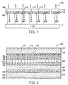
- Figure 1 illustrates a color tuned volume holographic optical element filtering light from a light source.
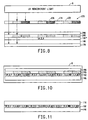
- Figure 2 illustrates the color tuned volume holographic optical element used as a multicolor transmission filter in a liquid crystal display apparatus.
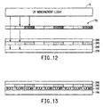
- Figure 3 is a graph of relative spectral power versus wavelength for a typical multicolor liquid crystal display light source.
- Figure 4 illustrates a photohardenable holographic recording film element.
- Figure 5 illustrates holographically imaging the recording film element to record a volume holographic optical element in the film element.
- Figure 6 illustrates curing the holographic recording film element.
- Figure 7 illustrates contacting the recording film element with a diffusing element.
- Figure 8 illustrates imagewise exposing the diffusing element to actinic radiation to polymerize diffusable monomer to varying degrees to color tune or selectively modify the wavelength response of the holographic recording film element.
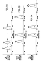
- Figures 9A, 9B and 9C are graphs of relative diffraction efficiency versus wavelength for a non-color tuned optical element, a partially color tuned optical element and a fully color tuned optical element, respectively.
- Figure 10 illustrates heating the holographic recording film element.
- Figure 11 illustrates attaching a support layer to the color tuned holographic recording film forming the holographic optical element.
- Figure 12 illustrates imagewise exposing the diffusing element to actinic radiation to polymerize diffusable monomer to varying degrees.
- Figure 13 illustrates contacting the recording film element with the diffusing element for a time sufficient to color tune or selectively modify the wavelength of light response by the recording film element.
- the color tuned volume holographic optical element 100 comprises a holographic recording film element 102 having a first surface 106 and a second surface 108.
- the first holographic recording film element 102 comprises at least a first plurality of pixel volumes 110 and a second plurality of pixel volumes 112.
- the first holographic recording film element 102 further comprises a third plurality of pixel volumes 114.
- the first plurality of pixel volumes 110, the second plurality of pixel volumes 112 and the third plurality of pixel volumes 114 are arranged in rows and columns.
- the first holographic recording film element 102 can be a single layer or more than one layer.
- Each one of the first pixel volumes 110 includes a color tuned volume holographic mirror that passes light with at least a first color (e.g., Red) wavelength band and reflects light with at least another color (e.g., Green) wavelength band.
- Each one of the second pixel volumes 112 includes a volume holographic mirror that passes light with at least the another color (e.g., Green) wavelength band and reflects light with at least the first color (e.g., Red) wavelength band.
- the volume holographic mirrors in the first pixel volumes 110 are color tuned and the holographic mirrors in the second pixel volumes 112 are not color tuned.
- each one of the first pixel volumes 110 includes a color tuned first volume holographic mirror that passes light with a first color (e.g., Red) wavelength band and reflects light with a second color (e.g., Green) wavelength band, a third color (e.g., Blue) wavelength band and a fourth color (e.g., near IR) wavelength.
- each one of the second pixel volumes 112 includes a non-color tuned second volume holographic mirror that passes light with the second color (e.g., Green) wavelength band and reflects light with the first color (e.g., Red) wavelength band, the third color (e.g., Blue) wavelength band and a fifth color (e.g., UV) wavelength band.
- each one of the third pixel volumes 114 includes a color tuned third volume holographic mirror that passes light with the third color (e.g., Blue) wavelength band and reflects light with the first color (e.g., Red) wavelength band, the second color (e.g., Green) wavelength band and a sixth color (e.g., mid IR) wavelength band.
- the third color e.g., Blue
- the first color e.g., Red
- the second color e.g., Green
- a sixth color e.g., mid IR
- the holographic mirrors are formed by fringes or gratings.
- the gratings of all holographic mirrors disclosed herein can be of any shape or slant achieved by conventional holographic methods.
- the gratings can be conformal gratings which are parallel to the surfaces 106,108 of the recording medium and/or non-conformal gratings which are non-parallel to the surfaces 106,108.
- a light source 2 is illustrated providing light towards the color tuned photohardened holographic recording film element 100.
- the light source 2 can emit light which includes the first color (e.g., Red) wavelength band, the second color (e.g., Green) wavelength band, the third color (e.g., Blue) wavelength band, the fourth color (e.g., Near Infrared) wavelength band, the fifth color (e.g., Ultraviolet) wavelength band, and/or the sixth color (e.g., Mid Infrared) wavelength band.
- the first color e.g., Red
- the second color e.g., Green
- the third color e.g., Blue
- the fourth color e.g., Near Infrared
- the fifth color e.g., Ultraviolet
- the sixth color e.g., Mid Infrared
- the letters in Figure 1 designating the color wavelength bands and the associated arrows illustrate whether the element 100 will pass or reflect the specific color wavelength band assuming that the light source 2 emits actinic radiation in such color wavelength band.
- the light source 2 also emits color wavelength bands other than the first, second, third, fourth, fifth and sixth color wavelength bands, such wavelength bands would also pass through the color tuned volume holographic optical element 100.
- the light source 2 can emit coherent, substantially coherent or noncoherent light.
- the color tuned volume holographic optical element 100 functions the same regardless of which side of the volume holographic optical element 100 the light source 2 is positioned.
- the first color wavelength band, the second color wavelength band, the third color wavelength band, the fourth color wavelength band, the fifth color wavelength band and the sixth color wavelength band are distinct wavelength bands of light separated by other wavelength bands.
- light having the first color wavelength band has a bandwidth of at least 5 nanometers (and more preferably within about 20-30 nanometers) and includes 612 nanometer which appears Red and is designated R in the Figures.
- light having the second color wavelength band has a bandwidth of at least 5 nanometers (and more preferably within about 20-30 nanometers) and includes 545 nanometer which appears Green and is designated G in the Figures.
- light having the third color wavelength band has a bandwidth of at least 5 nanometers (and more preferably within about 20-30 nanometers) and includes 436 nanometer which appears Blue and is designated B in the Figures.
- light having the fourth color wavelength band has a bandwidth of at least 5 nanometers (and more preferably within about 20-30 nanometers) and includes 741 nanometer which is near infrared light and is designated NIR in the Figures.
- light having the fifth color wavelength band has a bandwidth of at least 5 nanometers (and more preferably within about 20-30 nanometers) and includes 371 nanometer which is ultraviolet light and is designated UV in the Figures.
- light having the sixth color wavelength band has a bandwidth of at least 5 nanometers (and more preferably within about 20-30 nanometers) and includes 875 nanometer which is mid-infrared light and is designated MIR in the Figures.
- the color band designations in all pixel volumes throughout the Figures illustrate the color wavelength band(s) that is/are reflected by the pixel volume and all other color wavelengths pass through the pixel volumes. When two or more of these color band designations are listed together, it refers to light consisting essentially of the wavelength bands of each of the designated color bands.
- the first pixel volumes 110, the second pixel volumes 112 and the third pixel volumes 114 can be any shape and in any order in the recording film element 102. However, the volumes 110,112,114 do have sides which are part of the first and second surfaces 106,108 of the film element 102.
- Figure 1 depicts one row of a preferred embodiment of a two dimensional array of the volumes 110,112,114. Preferably, the pixels volumes 110,112,114 are ordered in each row of the array in a repeating sequence of one of the first pixel volumes 110, then one of the second pixel volumes 112, and then one of the third pixel volumes 114.
- the pixel volumes 110,112,114 in adjacent rows can be offset with respect to one another such that an intersection line between each pair of adjacent pixel volumes in one row is collinear or substantially collinear with a line that bisects a corresponding one of the pixel volumes in an adjacent row.
- the first holographic optical element 100 further optionally comprises a dimensionally stable substrate 116 having a planar surface supporting the first surface 106 of the film element 102.
- Figure 2 illustrates the color tuned volume holographic optical element 100 used as a multicolor transmission filter in a liquid crystal display 220.
- the transmission liquid crystal display apparatus comprises, in order, a first light polarizer 222, the holographic multicolor transmission filter 100, a liquid crystal display element 226, a first dimensionally stable substrate 224, a second light polarizer 228, and a light assembly 230.
- the light assembly 230 can comprise a light source 232, a reflector or intensifier 234, and a prefilter 236.
- the light source 232 emits light with the first color (e.g., Red) wavelength band, the second color (e.g., Green) wavelength band and the third color (e.g., Blue) wavelength band.
- the light source 232 may also emit light with other wavelength bands.
- the prefilter 236 is included to block passage of the other wavelength bands.
- Figure 3 is a graph of relative spectral power (e.g., milliwatts) versus wavelength ( ⁇ ) for a typical multicolor liquid crystal display light source.
- the prefilter 236 could be made to block passage of light having wavelength bands of about 400-425, 474-500, and 575-595 nanometers.
- the prefilter 236 is a volume holographic optical element adapted to pass the first color (e.g., Red) wavelength band, the second color (e.g., Green) wavelength band and the third color (e.g., Blue) wavelength band and to reflect other wavelength bands, such as wavelength bands of about 400-425, 474-500, and 575-595 nanometers.
- the second light polarizer 228 is for linearly polarizing light from the light assembly 230 such that light having only a first polarization passes through the polarizer 228.
- the liquid crystal display element 226 passes light or polarized modified light to the filter 100.
- the liquid crystal display element 226 is well known by those skilled in the art and is for selectively modifying the polarization of the light passing through an array of cells X,Y,Z such that the polarization of light passing through a first set of the cells X, a second set of the cells Y or a third set of the cells Z can be changed to a second linear polarization.
- Illustrative liquid crystal display elements are disclosed in the publications cited in the Background of the Invention section of this specification.
- the second polarization is typically perpendicular to the first polarization.
- the liquid crystal display element 126 can comprise, in order, a first circuitry layer 130, a first alignment layer 132, a liquid crystal layer 134, a second alignment layer 136, a second circuitry layer 138, and a leveling layer 140.
- the circuitry layer 130 provides a first side of an electrical drive circuit capable of modifying a particular first side orientation of liquid crystals in the liquid crystal layer 134 through the first alignment layer 132.
- the liquid crystal layer 134 confines liquid crystals in cells corresponding to each pixel volume in the filter 100.
- the second alignment layer 136 introduces a particular second side orientation to the liquid crystals in the liquid crystal layer 134.
- the second circuitry layer 138 provides a second side of the electrical drive circuit capable of modifying the particular second side orientation of liquid crystals in the liquid crystal layer 134 through the second alignment layer 136.
- the leveling layer 140 provides a rigid planar surface for the filter 100.
- the first light polarizer 222 passes light from the filter 200 having only the second polarization and blocks light of other polarizations.
- the liquid crystal display element 226 modifies or rotates the polarization of the light passing through the first set of cells X to the second polarization
- the light passes into the first pixel volumes 110 in which the first volume holographic mirrors pass light with the first color (e.g., Red) wavelength band through the first polarizer 222 to a viewer.
- the liquid crystal display element 226 modifies or rotates the polarization of the light passing through the second set of cells Y to the second polarization
- the light passes into the second pixel volumes 112 in which the second volume holographic mirrors pass light with the second color (e.g., Green) wavelength band through the first polarizer 222 to the viewer.
- the second color e.g., Green
- the liquid crystal display element 226 modifies or rotates the polarization of the light passing through the third set of cells Z to the second polarization, the light passes into the third pixel volumes 114 in which the third volume holographic mirrors pass light with the third color (e.g., Blue) wavelength band through the first polarizer 222 to the viewer.
- the third color e.g., Blue
- Figure 4 depicts a holographic recording film element 142 that can be used in making the first color tuned volume holographic optical element 100.
- the holographic recording film element 142 comprises, in turn, a cover sheet 144, an unimaged, unexposed holographic recording film element or layer 102' and a dimensionally stable support 146.
- a method for making a preferred embodiment of the first color tuned volume holographic optical element 100 will now be described starting with the unimaged, unexposed holographic recording film element 102'.
- the holographic recording film element 102' is fully sensitized.
- the cover sheet 144 is removed from the first surface 106 of the holographic recording film layer 102'.
- the first surface 106 of the film layer 104' is laminated on a reflector 156, such as a front surface mirror.
- An anti-reflection plate 148 is coupled through a first index matching fluid layer 152 to the dimensionally stable support 146. This results in a laminate structure which is depicted in Figure 5.
- a light source 4 is selected adapted to simultaneously emit coherent or substantially coherent light consisting essentially of the first color (e.g., Red) wavelength band, the third color (e.g., Blue) wavelength band and the fifth color (e.g., UV) wavelength band.
- the light source can be any convenient light source that provides actinic radiation of appropriate wavelengths and intensity to initiate photopolymerization in the recording film layer 102'.
- Conventional sources of actinic radiation include fluorescent, mercury vapor, mercury-xenon, metal additive and arc lamps.
- Useful sources of coherent radiation are lasers whose emissions fall within or overlap the absorption bands of the initiator system in the recording film layer 102'.
- Light from the light source 6 is directed, in turn, through the anti-reflection plate 148, the holographic recording film layer 102' onto the reflector 156.
- the reflector 156 reflects the light back through the holographic recording film layer 102' such that the reflected light interferes with the light passing through the film layer 102' towards the reflector 156.
- This interference holographically images or imagewise holographically exposes the holographic film layer 102' to record a second volume holographic optical element in the form of a holographic mirror adapted to uniformly reflect light consisting essentially of the fifth color (e.g., UV) wavelength band, the third color (e.g., Blue) wavelength band and the first color (e.g., Red) wavelength band.
- the fifth color e.g., UV
- the third color e.g., Blue
- the first color e.g., Red
- the holographic mirror is a volume phase hologram.
- the volume phase hologram can be a reflection hologram or a transmission hologram. Preferably, it is a reflection hologram.
- the holographic film layer 102' recorded to be the second volume holographic optical element in the form of a holographic mirror is designated layer 102" in the Figures.
- holographic imaging or imagewise holographic exposing is performed in a single step which occurs for about 20 seconds. However, alternatively, this holographic imaging can be performed in multiple steps.
- light having only the first (e.g., Red) wavelength band can be directed from the light source 6 through the laminate depicted in Figure 5 recording a first holographic mirror in the layer 102' that uniformly reflects the first (e.g., Red) wavelength band through out the layer 102'.
- light having only the third (e.g., Blue) wavelength band can be directed from the light source 6 through the laminate depicted in Figure 5 recording a second holographic mirror in the layer 102' that uniformly reflects the third (e.g., Blue) wavelength band through out the layer 102'.
- light having only the fifth (e.g., Ultraviolet) wavelength band can be directed from the light source 6 through the laminate depicted in Figure 5 recording a third holographic mirror in the layer 102' that uniformly reflects the fifth (e.g., Ultraviolet) wavelength band through out the layer 102'.
- the different light bands may be directed to holographically expose the layer 102' in any order.
- the resulting laminate structure can be optionally cured, fixed or exposed to substantially polymerize any monomer and fix the holographic mirror in the laminate structure.
- the cured layer is referred to by the number 102'' in the Figures.
- This can be accomplished, as illustrated in Figure 6, by using noncoherent actinic radiation, such as from a broad band ultraviolet light source 6, to flood expose the laminate structure.
- the term "broad band ultraviolet light” means light in the spectral region of about 300 through 450 nanometers.
- This step provides an exposure level of about 100 millijoules per squared centimeter (mJ/cm 2) , but the exposure level can be greater.
- This step typically occurs for about one minute, but can occur longer.
- This step photo hardens or substantially photo hardens any remaining photosensitive material in the laminate structure.
- a solid or substantially solid diffusing element 160 is laminated or applied to the layer 102''.
- the diffusing element 160 can comprise, in turn, a cover sheet 244, a diffusing layer 245 with the diffusable monomer in the layer 245 and a dimensionally stable support 246.
- the cover sheet 244 is removed from the diffusing layer 245.
- the diffusing layer is placed in contact with the holographic recording film element 102''. Pressure and heat can be applied such as through a pair of heated rollers 162 to ensure good contact between the layers.
- the diffusing element 245 is imagewise exposed to actinic radiation to polymerize the monomer to varying degrees to selectively modify the wavelength response of the holographic optical element 102" by the diffusion of monomer from the diffusion element 245 to form the first color tuned volume holographic optical element.
- Figure 8 illustrates one way of doing this.
- light source 6 can be used.
- a photomask 170 can be used having a first set of pixels 172, a second set of pixels 174 and a third set of pixels 176.
- the first set of pixels 172 is partially transparent to light from light source 6.
- the second set of pixels 174 is completely transparent to light from light source 6.
- the third set of pixels 176 is opaque or completely blocks light from light source 6.
- Light from light source 6 is directed, in turn, through the photomask 170, the diffusing element 245, and the first holographic optical element 102".
- An antihalation layer 178 can be laminated to the substrate 146 to reduce reflection and/or refraction of the light back through the holographic optical element 102''.
- the regions of the hologram in contact with the unexposed regions of the diffusion element 245 will be shifted to longer response wavelengths than the regions of the hologram in contact with the exposed regions of the diffusion element 245. More specifically, light that passes through the first set of pixels 172 partially polymerizes the diffusable monomer in the pixels 172.
- Figures 9A-9C illustrate this process.
- Figures 9A-C are graphs of relative diffraction efficiency versus wavelength reflected by a non-color tuned optical element (or non-color tuned pixel volumes), a partially color tuned optical element (or partially tuned pixel volumes) and a fully color tuned optical element (or fully color tuned pixel volumes), respectively.
- bell curves exist at the first, third, and fifth color wavelength bands centered about 612 nanometer, 438 nanometer, and 371 nanometer, respectively.
- bell curves exist at the second, third, and fourth color wavelength bands centered about 530 nanometer, 449 nanometer, and 741 nanometer, respectively.
- bell curves exist at the first, second, and sixth color wavelength bands centered about 626 nanometer, 531 nanometer, and 875 nanometer, respectively.
- the shape of the curves is only illustrative and the holographic mirrors can be designed to reflect bands of light having various curves when plotted against relative spectral power.
- Each of the first through sixth bands has an average bandwidth of about 30 nanometers.
- Figure 9A illustrates performance of the second holographic optical element 102' formed by the holographic exposing illustrated in Figure 5.
- the second holographic optical element 102' reflects light having the first, third and fifth color wavelength bands. All other light including the Green wavelength band passes through the second holographic optical element 102'. Since no monomer diffuses into the second pixel volumes 112, Figure 9A also illustrates the performance of the second pixel volumes 112 in the first holographic optical element 100 formed by the color tuning step illustrated in Figure 8.
- Figure 9B illustrates the situation where some monomer diffuses into the first pixel volumes 110 partially swelling them. This moves the performance of the first pixel volumes slightly towards the MIR end of the light spectrum. As such, Figure 9B illustrates performance of the first pixel volumes 110 in the holographic optical element 102 formed by the color tuning step illustrated in Figure 8. More specifically, Figure 9B illustrates a 21% swelling of the holographic mirrors illustrated in Figure 9A.
- the first pixel volumes 110 in the holographic optical element 102 reflect light having the second, third and fourth color wavelength bands. All other light including the Red wavelength band passes through the first pixel volumes 110.
- Figure 9C illustrates the situation where unhindered monomer diffuses into the third pixel volumes 114 fully swelling them. This moves the performance of the third pixel volumes closer to the MIR end of the light spectrum. As such, Figure 9C illustrates performance of the third pixel volumes 114 in the holographic optical element 102 formed by the color tuning step illustrated in Figure 8. More specifically, Figure 9C illustrates a 43% swelling of the holographic mirrors illustrated in Figure 9A.
- the third pixel volumes 114 in the holographic optical element 102 reflect light having the first, second, and sixth color wavelength bands. All other light including the Blue wavelength band passes through the third pixel volumes 114.
- the antihalation layer 178 is removed. Then, the holographic recording film can be heated, such as in an oven 8, to increase the refractive index modulation, efficiency and bandwidth of the holographic mirrors. See Figure 10.
- Figure 11 illustrates the steps of removing the diffusing element 245 and its substrate 246 and laminating the layer 102 to the dimensionally stable support 116.
- the substrate 246 is removed, this results in the first holographic optical element 100 illustrated in Figure 1.
- the diffusing element 245 can remain on the layer 102 and become part of the first holographic optical element 100.
- the resulting first holographic optical element 100 can be used as a filter in an LCD apparatus that uses a light source with a power distribution as illustrated in Figure 3.
- the first holographic optical element 100 can have different wavelength bands and bandwidths than those illustrated in Figures 9A-C in which case it can be used to filter a light source for an LCD apparatus with relative power peaks designed or selected to correspond to the relative power peaks filtered by the element 100.
- Figures 12 and 13 illustrate an alternative method for making the first color tuned volume holographic optical element 100.
- This second method is the same as the first method, except in this method the diffusing element 245 is imagewise exposed to actinic radiation to polymerize the monomer to varying degrees before it is placed in contact with the layer 102'.
- the diffusing element 245 and the layer 102' are placed in contact for a time sufficient to selectively modify the wavelength of light response of the second volume holographic optical element 102' by diffusion of the monomer from the solid diffusing element 245 to form the first color tuned volume holographic optical element 100.
- Figure 12 illustrates directing light from light source 6, in turn, through the photomask 170, the substrate 246, the diffusing element 245, another dimensionally stable substrate 248 and into an antihalation layer 278. This imagewise exposes the diffusing element 245 to actinic radiation to polymerize the monomer to varying degrees.
- the substrate 248 and the antihalation layer 278 are removed and the film element is contacted with the diffusing element 245 for a time sufficient to selectively modify the wavelength of light response of the second volume holographic optical element by diffusion of the monomer from the solid diffusing element to form the first color tuned volume holographic optical element.
- the laminate formed after the step illustrated in Figure 13 can be heated as described in relation to the prior method.
- a dimensionally stable substrate 116 is laminated to the layer 102.
- the substrate 146 is removed.
- the resulting laminate is the first color tuned volume holographic element 100 illustrated in Figure 1.
- the first holographic recording film element 102 comprises a plurality of substantially solid, holographic recording films.
- the film element 102 comprises a first holographic recording film layer, a second holographic recording film layer and a third holographic recording film layer, laminated on top of one another.
- the first pixel volumes 110 are formed in the first layer
- the second pixel volumes 112 are formed in the second layer
- the third pixel volumes 114 are formed in the third layer.
- One method of making this embodiment is as follows. First mirrors are holographically imaged in the first layer. Second mirrors are holographically imaged in the second layer. Third mirrors are holographically imaged in the third layer.
- the layers can been fully sensitized or only sensitized to the wavelength bands used to image the mirrors. Then the layers are laminated to one another. Then a diffusing element is applied to one side of the laminated layers. Then actinic radiation is directed through photomask 170, the diffusing element and the laminated layers as illustrated in Figure 8 except the single layer 102'' is replaced with the 3 laminated layers. Alternatively, the three laminated layers can be substituted for the single layer 102 in Figure 13 to cause diffusion of monomer from the pre-exposed diffusion element.
- the dimensionally stable substrates 116, 224 and 248 can be made of rigid transparent materials and preferably are made of glass or plastic. Each of these substrates can be the same or different.
- the dimensionally stable supports 146, 246 are required to be transparent if irradiation is to be carried out through the supports.
- the supports 146, 246 may be any dimensionally stable material typically used with photopolymer films.
- Preferred materials for the supports 146, 246 are polymer films, such as polyethylene, polypropylene, cellulose, and polyethylene terephthalate.
- cover sheets 144, 244 function to protect the film layers until ready for use.
- These cover sheets generally are a polymer film, such as polyethylene, polypropylene, or polyethylene terephthalate.
- the unimaged, unexposed holographic film layer 102' is a dry film of photohardenable or photosensitive material. Holograms are recorded in materials that produce a spatial pattern of varying refractive index, rather than optical density, when exposed to light. Holographic recording materials are described in a number of references, such as, L. Solymer and D. J. Cook, Volume Holography and Volume Gratings, Academic Press, New York, 1981, Chapter 10, pages 254-304; and W. K. Smothers, B. M. Monroe, A. M. Weber and D. E. Keys, Photopolymers for Holography, SPIE Vol. 1212, Practical Holography IV (1990). Early developments in holography are described by E. N. Leith and J.
- Preferred recording materials for use in this invention are photopolymerizable compositions, dichromated gelatin, and silver halide emulsions.
- Photopolymerizable compositions are disclosed in Haugh, U.S. Patent 3,658,526; Chandross, U.S. Patent 3,993,485; and Fielding, U.S. Patents 4,535,041 and 4,588,664.
- Preferred photopolymerizable compositions are disclosed in Keys, U.S. Patent 4,942,102; Monroe, U.S. Patent 4,942,112; Smothers, U.S. Patent 4,959,284; Trout, U.S. Patent 4,963,471; Smothers, U.S. Patent 5,236,808; and Smothers, U.S. Patent 5,256,520; as well as in U.S. Patent application serial numbers 08/146,817 and 08/146,816.
- the compositions used in the preferred recording film element are dry films.
- the diffusing element 245 is a dry film that comprises a monomer, an initiator system, and a binder, on a support.
- the monomer diffuses into the film element, thereby increasing the wavelength of light reflected by the hologram.
- any of the numerous conventional photopolymerizable monomers may be used in the diffusing element 245 provided the selected monomer is diffusable into the recording element 102' and compatible with it. If the holographic recording element 102' is a photopolymer, the monomer in the diffusing element 245 may be the same as that contained in the recording element 102, a monomer with a similar refractive index, a totally different monomer, or a mixture of various monomers.
- the initiator system in the diffusing element 245 may be any of the conventional initiator systems used in photopolymerizable compositions. Initiator systems that do not contain a component which absorbs visible radiation may be used to advantage. Diffusion of materials that absorb visible light may impart unwanted color to the final hologram. Initiator systems that do not absorb visible light can not be irradiated by visible radiation.
- the binder in the diffusing element 245 may be any of the conventional binders used in photopolymerizable compositions. If the diffusing element 245 and recording element 102' have the same binder or if the binder of the film is a compatible transparent material, the diffusion element 245 may be permanently laminated to the photosensitive film to serve as a protective overcoat.
- the diffusing element 245 may contain plasticizers, thermal stabilizers, coating aids, antihalation agents, and the like that are commonly added to photopolymerizable compositions.
- the diffusion element 245 may be prepared using conventional coating techniques.
- the ingredients of the dry film are dissolved in a suitable solvent, coated onto the support, and the solvent evaporated. After the solvent has evaporated, the coversheet is laminated to the dry film. Alternatively, the dry film may be coated onto the coversheet, and the support laminated to the dry film.
- suitable materials for the diffusing element, methods of making the diffusing element, and methods of using diffusing elements to color tune holograms are described in U.S. Patents 5,182,180 and 4,959,283, which are incorporated by reference herein.
- Antireflection plate 148 functions to prevent back reflection of imaging light and is commercially available from CVI Laser Corporation with offices at Albuquerque, New Mexico.
- the photomask layer 170 functions to block all light from passing through the layers and can be made of patterned chromium or silver halide on glass. Alternatively, imagewise radiation can be carried out through a half-tone or continuous tone transparency. Other means of imagewise irradiation include exposure through a transmissive device, such as an absorptive filter, and exposure using a scanning laser, electron beam, or the like.
- the index matching fluid layer 152 is preferably hydrocarbons and most preferably is Isopar® L available from Chemcentral Corporation with offices at Southeastern Pennsylvania 19399 and Cargille A1.59 available from R.P. Cargille Laboratories, Inc. at Cedar Grove, New Jersey 07009.
- the antihalation layers 178, 278 function to absorb light and prevent back reflection. Suitable antihalation layers are black spray paint on float glass or highly absorbing films such as Chronar® commercially available from E. I. du Pont de Nemours and Company of Wilmington, Delaware.
- This example illustrates the formation of a high efficiency 3-color holographic mirror in single holographic photopolymer layer. Furthermore, it demonstrates the capability to form high efficiency multicolor mirrors required for color filters with 2-color mirrors and virtual black border with 3-color mirrors.
- TFE/VAc tetrafluoroethylene/vinyl acetate
- the solution was extrusion dye coated onto a 50 ⁇ m Mylar® base sheet at a speed of about 31 ft/min (15 cm/sec) using a web coater.
- the solvent was evaporated by passing the coated film through a three zone drier.
- the first zone was at 120°F (49°C), the second at 140°F (60°C), and the third at 160°F (71°C).
- a coversheet of 23 micron Mylar® (polyethylene terephthalate film) was laminated to the coating as it exited the drier. Dry coating thickness was 20 ⁇ m.
- the coversheet was removed from the photopolymer and the tacky photopolymer was laminated to a section of 100mmx125mmx3.2mm float glass. Excess film was trimmed away so that the laminated film fit within the edges of the glass substrate.
- the base sheet was left in place during subsequent processing.
- the imaging plate was coupled to an anti-reflection (AR) plate using Isopar® L (Exxon) to provide a good match of the refractive index of the film to the AR plate.
- a front-surface aluminum mirror was coupled to the surface using the same index matching fluid. Pressure was applied to the stack of plates to provide thin, even index matching fluid layers. The stack of plates was then mounted in a conventional plate holder mounted on an imaging stage and allowed to settle for more than 30 seconds.
- An argon ion laser with emissions at 458nm, a diode-pumped, frequency-doubled YAG laser with emissions at 532nm and a krypton ion laser with emissions at 647nm were combined by appropriate dichroic mirrors in the conventional way to form a 3-color laser beam.
- This 3-color beam was passed through achromatic optics to form an expanded, collimated, 3-color beam.
- a shutter was installed between the expansion optics and the imaging stage. The imaging plate was rotated on the imaging stage such that the 3-color laser beam direction was perpendicular to the imaging stack.
- Holographic mirrors were formed by exposing with the collimated laser beam oriented perpendicular to the film plane and passing, in order, through the anti-reflection plate, Isopar® L layer, base sheet, holographic photopolymer, glass plate and Isopar® L layer and then reflecting back onto itself off the mirror.
- the exposure energy of the imaging beam was 8.6 mJ/cm 2 at 647nm, 2.9 mJ/cm 2 at 532nm and 2.2 mJ/cm 2 at 458nm.
- Four 20 mm diameter regions were formed on the plate using identical imaging conditions. The imaging plate was translated to an unimaged region of the film plate after each exposure and allowed to settle for 30 seconds before a subsequent exposure. After imaging, the AR plates, front surface mirror and Isopar® L layers were removed.
- the imaging plate was overall exposed to ultraviolet and visible light from a Theimer-Strahler #5027 mercury-arc lamp (Exposure Systems Corp., Bridgeport, Conn.) mounted in a Douthitt DCOP-X exposure unit (Douthitt Corp., Detroit, Michigan) for 120 sec (about 150 mJ/cm 2 ).
- the imaging plate was thermally processed by heating at 120°C for 2 hours in a forced-air convection oven.
- the transmission spectra of the holographic mirror was recorded using a standard double-beam spectrophotometer (Perkin-Elmer model Lambda-9) with the sample beam oriented perpendicular to the hologram film plane.
- the results are shown in Table 1 and demonstrate that three high efficiency holographic mirrors (i.e., a 3-color holographic mirror) have been formed at the three wavelengths (448, 520, and 633 nm) within a single photopolymer layer.
- This example demonstrates the ability to alter the playback wavelength of a 3-color holographic mirror using a color tuning film, which ability is necessary for formation of holographic mirrors suitable for use as holographic LCD color filters made according to the process of this invention.
- Holographic mirrors were produced as described in Example 1. After heat processing, base film was removed from two of the eight holographic mirror regions. A color tuning film (DuPont OmniDex® GA2-red color tuning film (CTF)) was stripped of its cover sheet and the tacky photopolymer was laminated to the exposed photopolymer surface of the multicolor mirrors. The plate bearing the holographic mirrors and color tuning film was then thermally processed by heating at 100°C for 30 minutes in a forced-air convection oven. The transmission spectra of the holographic mirror was recorded using a standard double-beam spectrophotometer (Perkin-Elmer model Lambda-9) with the sample beam oriented perpendicular to the hologram film plane.
- CTF color tuning film
- Results for two unprocessed 3-color holographic mirrors are shown in Table 2, which illustrate that there is no shift in playback wavelength without color tuning (unprocessed case).
- Results for two processed 3-color holographic mirrors are shown in Table 3, which illustrate that significant shifts occur in playback wavelength with color tuning (processed case).
- three sets of 16 high efficiency single-color mirrors are formed in three separate plates using the same single holographic photopolymer layer in each case.
- the three sets of holographic mirrors are individually laminated together to form a three layer photopolymer stack with red mirrors in one layer of the stack, green mirrors in a second layer of the stack and blue mirrors in another layer of the stack. All three layers are swelled by applying a single color tuning film layer to the three layer holographic stack and heating. This is a similar demonstration to example 2, but with each color residing in a different part of the total holographic film.
- the solution was extrusion dye coated onto a 50 ⁇ m Mylar® base sheet at a speed of about 31 ft/min (15 cm/sec) using a web coater.
- the solvent was evaporated by passing the coated film through a three zone drier.
- the first zone was at 120°F (49°C), the second at 140°F (60°C), and the third at 160°F (71°C).
- a coversheet of 23 micron Mylar® (polyethylene terephthalate film) was laminated to the coating as it exited the drier. Dry coating thickness was 20 ⁇ m.
- the coversheet was removed from the photopolymer and the tacky photopolymer was laminated to a section of 100mmx125mmx3.2mm float glass. Excess film was trimmed away so that the laminated film fit within the edges of the glass substrate.
- the base sheet was left in place during subsequent processing.
- the imaging plate was coupled to an anti-reflection (AR) plate using Isopar® L (Exxon) to provide a good match of the refractive index of the film to the AR plate.
- a front-surface aluminum mirror was coupled to the surface using the same index matching fluid. Pressure was applied to the stack of plates to provide thin, even index matching fluid layers. The stack of plates was then mounted in a conventional plate holder mounted on an imaging stage and allowed to settle for more than 30 seconds.
- An argon ion laser with emissions at 458nm, a dye laser with emissions at 576nm and a krypton ion laser with emissions at 647nm were combined by appropriate dichroic mirrors in the conventional way to form a 3-color laser beam.
- This 3-color beam was passed through achromatic optics to form an expanded, collimated, 3-color beam.
- Shutters were installed so that each color could be individually controlled.
- the imaging plate was rotated on the imaging stage such that the 3-color laser beam direction was perpendicular to the imaging stack.
- Holographic mirrors were formed by exposing with the collimated laser beam oriented perpendicular to the film plane and passing, in order, through the anti-reflection plate, Isopar® L layer, base sheet, holographic photopolymer, glass plate and Isopar® L layer and then reflecting back onto itself off the mirror. Three plates were imaged separately with sixteen spots, each at a single wavelength. The exposure energy of the imaging beam for the plate imaged at 647nm was 50 mJ/cm 2 , for the plate imaged at 576nm was 50 mJ/cm 2 and for the plate imaged at 458nm was 50 mJ/cm 2 . Sixteen 20 mm diameter regions were formed on each plate using identical imaging conditions. The imaging plate was translated to an unimaged region of the film plate after each exposure and allowed to settle for 30 seconds before a subsequent exposure. After imaging, the AR plates, front surface mirror and Isopar® L layers were removed.
- the base and photopolymer of the plate imaged at 647nm and the base and photopolymer of the plate imaged at 576nm were delminated for their respective glass substrates and the photopolymer side of each was laminated at a temperature of about 60°C to each other with the proper alignment so that the sixteen spots of each film laid one over top of the other.
- the resulting sandwich of base/photopolymer/photopolymer/base was heated to 120°C for 5 minutes and then allowed to cool. The base was removed from the photopolymer imaged at 647 nm.
- the base and photopolymer of the plate imaged at 458nm was then delaminated from its glass substrate and the photopolymer side was laminated to the exposed photopolymer layer from the previous lamination, again with the sixteen spots aligned to each other.
- the lamination was performed at about 60°C and resulted in overlapping red, green and blue mirrors.
- the sandwich of base/photopolymer/photopolymer/photopolymer-/base was then heat at 120°C for 5 minutes.
- the base from the photopolymer imaged at 458nm was delaminated and another layer of unexposed photopolymer was laminated to the three-photopolymer layer stack. This film served as the diffusion element much as the GA2-red color tuning film in the previous examples did.
Description
- CTFE
- Chlorotrifluoroethylene
- DE (%)
- Diffraction efficiency expressed as a percent; DE (%) = Idif/Io x 100, where Idif is the intensity of the diffracted beam of actinic radiation and Io is the intensity of the incident beam corrected for absorption in the film sample and for spurious reflections off the film sample
- FC-430
- Fluorad® FC-430; fluoroaliphatic polymeric esters; CAS 11114-17-3; 3M Company, St. Paul, MN
- GA2-red
- OmniDex® GA2-red color tuning film (CTF); E. I. du Pont de Nemours, Inc., Wilmington, DE; OmniDex® is a registered trademark of E. I. Du Pont de Nemours and Company
- Isopar® L
- An aliphatic hydrocarbon product; Exxon Company, Houston, TX
- JAW
- Cyclopentanone, 2,5-bis[2,3,6,7-tetrahydro-1H,5H-benzo[i,j]quinolizin-9-yl)methylene]-
- MMT
- 4-Methyl-4H-1,2,4-triazole-3-thiol; CAS 24854-43-1
- Mylar® film
- Polyethylene terephthalate film; registered trademark of E. I. du Pont de Nemours and Company, Wilmington, DE
- NVC
- N-Vinyl carbazole; 9-vinyl carbazole; CAS 1484-13-5
- Photomer® 4039
- Phenol ethoxylate monoacrylate; CAS 56641-05-5; Henkel Process Chemical Company, Ambler, PA
- PI-B
- 4,5-diphenyl-1-[4,5-diphenyl-2-(2,3,5-trichlorophenyl)-2H-imidazol- 2-yl]-2-(2,3,5-trichlorophenyl)-1H-imidazole
- PI-A
- 4,5-bis(4-chlorophenyl)-1-[4,5-bis(4-chlorophenyl)-2-(2,3,5-trichlorophenyl)-2H-imidazol-2-yl]-2-2,3,5-trichlorophenyl)-1H-imidazole
- PVA
- Poly(vinyl alcohol)
- Sartomer 349
- Ethoxylated bisphenol A diacrylate; CAS 24447-78-7; Sartomer Company, West Chester, PA
- SD-A
- 3-[(1-ethyl-1,2,3,4-tetrahydro-6 quinolinyl)methylene]-2,3-dihydro-4H-1-benzopyran-4-one; CAS 75535-23-8
- SD-B
- 2,4-bis[(3-ethyl-2(3H)-benzothiazolylidene) ethylidene]-8-methyl-8-azabicyclo[3.2.1]octan-3-one; CAS 154482-35-6
- SD-C
- 1-ethyl-2-[[3-[(1-ethyl-1,3-dihydro-5-methoxy-3,3-dimethyl-2H-indol- 2-ylidene)methyl]-2-hydroxy-4-oxo-2-cyclobuten-1-ylidene]methyl]-5-methoxy-3,3-dimethyl-3H-indolium hydroxide inner salt; CAS - none on computer files (STN International)
- Spot#
- Area/pixel/region (identified by number) of the HRF that is imaged in the examples of this specification
- TFE
- Tetrafluoroethylene
- TMPTMA
- Trimethylol propane trimethacrylate
- VAc
- Vinyl acetate
- VOH
- Vinyl alcohol
- (λ)max (nm)
- Wavelength of actinic radiation showing the maximum diffraction efficiency (DE (%)) from the transmission spectrum of a holographic mirror
| spot # | λmax (nm) | DE (%) | λmax (nm) | DE (%) | λmax (nm) | DE (%) |
| 1 | 633.7 | 88.8 | 520.6 | 92.1 | 448.5 | 90.0 |
| 2 | 633.7 | 88.8 | 520.8 | 91.3 | 448.6 | 89.0 |
| 3 | 633.7 | 89.5 | 520.7 | 89.5 | 448.5 | 86.2 |
| 4 | 633.9 | 87.7 | 520.8 | 91.5 | 448.7 | 86.8 |
| spot # | λmax (nm) | DE (%) | λmax (nm) | DE (%) | λmax (nm) | DE (%) |
| 1 | 633.3 | 90.0% | 520.4 | 91.7% | 448.3 | 85.9% |
| 2 | 633.8 | 91.7% | 520.9 | 93.5% | 448.5 | 83.4% |
| spot # | λmax (nm) | DE (%) | λmax (nm) | DE (%) | λmax (nm) | DE (%) |
| 1 | 756.5 | 86.8% | 621.0 | 83.4% | 528.6 | 63.7% |
| 2 | 761.7 | 85.5% | 625.1 | 80.9% | 537.2 | 62.8% |
| E (mJ/cm2) | λmax | DE (%) | λmax | DE (%) | λmax | DE (%) |
| 0 | 695.3 | 95% | 614.9 | 99% | 491.5 | 98% |
| 7 | 656.2 | 96% | 584.1 | 99% | 461.8 | 98% |
| 12 | 649.7 | 95% | 577.6 | 99% | 456.4 | 98% |
| 16.6 | 646.8 | 95% | 575.6 | 99% | 454.6 | 99% |
Claims (15)
- A color tuned volume holographic optical element (100) comprising:wherein:a photohardened holographic recording film element (102) comprising a first plurality of pixel volumes (110), a second plurality of pixel volumes (112), and a third plurality of pixel volumes (114);each one of the first pixel volumes (110) includes a color tuned volume holographic mirror that passes light with a first color wavelength band and reflects light with a second color wavelength band, a third color wavelength band and a fourth color wavelength band;each one of the second pixel volumes (112) includes a non-color tuned volume holographic mirror that passes light with the second color wavelength band and reflects light with the first color wavelength band, the third color wavelength band and a fifth color wavelength band; andeach one of the third pixel volumes (114) includes a color tuned volume holographic mirror that passes light with the third color wavelength band and reflects light with the first color wavelength band, the second color wavelength band and a sixth color wavelength band.
- The element of claim 1, wherein the first color wavelength band has a width of at least 5 nanometers and includes 634 nanometer, the second color wavelength band has a width of at least 5 nanometers and includes 528 nanometer, and the third color wavelength band has a width of at least 5 nanometers and includes 440. nanometer.
- The element of claim 1 or 2, wherein the fourth color wavelength band has a width of at least 5 nanometers and includes 760 nanometer, the fifth color wavelength band has a width of at least 5 nanometers and includes 367 nanometer, and the sixth color wavelength band has a width of at least 5 nanometers and includes 912 nanometer.
- The element of any one of claims 1-3, wherein the film element (102) comprises a single photohardened holographic recording film.
- The element of any one of claims 1-3, wherein the film element (102) comprises a plurality of photohardened holographic recording films.
- A transmission liquid crystal display apparatus (220) comprising, in order:wherein:a light assembly (230) which emits light with a first color wavelength band, a second color wavelength band and a third color wavelength band;a first light polarizer (228) for passing light from the light assembly (230) having a first polarization;a liquid crystal display element (226) for selectively modifying the polarization of the light passing through an array of cells such that the polarization of light passing through a first set, a second set or a third set of the cells can be changed to a second polarization;a color tuned volume holographic optical elements (100) as claimed in any preceding claim; anda second light polarizer (222) for passing light having a second polarization;when the liquid crystal display element (226) modifies the polarization of the light passing through the first set of cells to the second polarization, the light passes into the first pixel volumes (110) in which the first volume holographic mirrors pass light with the first color wavelength band through the second polarizer (222) to a viewer;when the liquid crystal display element (226) modifies the polarization of the light passing through the second set of cells to the second polarization, the light passes into the second pixel volumes (112) in which the second volume holographic mirrors pass light with the second color wavelength band through the second polarizer (222) to the viewer; andwhen the liquid crystal display element (226) modifies the polarization of the light passing through the third set of cells to the second polarization, the light passes into the third pixel volumes in which the third volume holographic mirrors pass light with the third color wavelength band through the second polarizer (222) to the viewer.
- The transmission liquid crystal display apparatus (220) of claim 6, further comprising a pre-filter adjacent the light assembly (230) for reflecting and/or absorbing light with other color wavelength bands.
- A method of making a color tuned volume holographic optical element (100) as claimed in claim 1, comprising:holographically exposing a holographic film element (102') with coherent or substantially coherent light to record a volume holographic optical element adapted to uniformly reflect light having a fifth color wavelength band, the third color wavelength band and the first color wavelength band;contacting a solid or substantially solid diffusing element (160) containing a diffusable monomer with the film element; andimagewise exposing the diffusing element to actinic radiation to polymerize the monomer to varying degrees to selectively modify the wavelength response of the holographic optical element (102") by the diffusion of monomer from the diffusion element (245) to form the first color tuned volume holographic optical element.
- The method of claim 8, wherein the imagewise exposing step is performed prior to the contacting step.
- The method of claim 8 or 9, further comprising after the holographically exposing step and before the contacting step, curing the holographic recording film element by exposing it to actinic radiation to substantially polymerize any monomer and fix the holographic mirrors in the film element.
- The method of claim 8 or 9, further comprising after the imagewise exposing and contacting steps, heating the holographic recording film to increase the refractive index modulation, efficiency and bandwidth of the holographic mirrors.
- The method of claim 8 or 9, wherein the film element comprises a single, substantially solid, holographic recording film.
- The method of claim 8 or 9, wherein the film element comprises a plurality of substantially solid, holographic recording films.
- The method of claim 8 or 9, wherein the first color wavelength band has a width of at least 5 nanometers and includes 634 nanometer, the second color wavelength band has a width of at least 5 nanometers and includes 528 nanometer, and the third color wavelength band has a width of at least 5 nanometers and includes 440 nanometer.
- The method of claim 14, wherein the fourth color wavelength band has a width of at least 5 nanometers and includes 760 nanometer, the fifth color wavelength band has a width of at least 5 nanometers and includes 367 nanometer, and the sixth color wavelength band has a width of at least 5 nanometers and includes 912 nanometer.
Applications Claiming Priority (3)
| Application Number | Priority Date | Filing Date | Title |
|---|---|---|---|
| US08/258,036 US5526145A (en) | 1994-06-10 | 1994-06-10 | Color tuned holographic optical elements and methods of making and using the elements |
| PCT/US1995/006707 WO1995034833A1 (en) | 1994-06-10 | 1995-06-02 | Color tuned holographic optical elements and methods of making and using the elements |
| US258036 | 1999-02-25 |
Publications (2)
| Publication Number | Publication Date |
|---|---|
| EP0764283A1 EP0764283A1 (en) | 1997-03-26 |
| EP0764283B1 true EP0764283B1 (en) | 2002-04-24 |
Family
ID=22978829
Family Applications (1)
| Application Number | Title | Priority Date | Filing Date |
|---|---|---|---|
| EP95922901A Expired - Lifetime EP0764283B1 (en) | 1994-06-10 | 1995-06-02 | Color tuned holographic optical elements and methods of making the elements |
Country Status (6)
| Country | Link |
|---|---|
| US (1) | US5526145A (en) |
| EP (1) | EP0764283B1 (en) |
| JP (1) | JPH10501630A (en) |
| DE (1) | DE69526500T2 (en) |
| TW (1) | TW293089B (en) |
| WO (1) | WO1995034833A1 (en) |
Families Citing this family (36)
| Publication number | Priority date | Publication date | Assignee | Title |
|---|---|---|---|---|
| JPH07253575A (en) * | 1994-03-16 | 1995-10-03 | Hitachi Ltd | Color liquid crystal display device |
| JP3256407B2 (en) * | 1995-05-19 | 2002-02-12 | シャープ株式会社 | Reflective color liquid crystal display |
| JP3112393B2 (en) * | 1995-05-25 | 2000-11-27 | シャープ株式会社 | Color display |
| US5680231A (en) * | 1995-06-06 | 1997-10-21 | Hughes Aircraft Company | Holographic lenses with wide angular and spectral bandwidths for use in a color display device |
| FR2738645B1 (en) * | 1995-09-12 | 1997-10-03 | Thomson Csf | SYSTEM FOR ILLUMINATING AN ELECTROOPTIC COLOR VISUALIZATION SCREEN |
| US5737045A (en) * | 1995-09-22 | 1998-04-07 | Ois Optical Imaging Systems, Inc. | LCD with notch filter |
| US6088076A (en) * | 1996-02-02 | 2000-07-11 | Casio Computer Co., Ltd. | Liquid crystal display apparatus using holographic optical element |
| US7215451B1 (en) * | 1996-04-15 | 2007-05-08 | Dai Nippon Printing Co., Ltd. | Reflection type diffuse hologram, hologram for reflection hologram color filters, etc., and reflection type display device using such holograms |
| EP2254002A1 (en) * | 1996-07-22 | 2010-11-24 | Dai Nippon Printing Co., Ltd. | Hologram-recorded medium and method of fabricating hologram-recorded media |
| KR100206688B1 (en) * | 1996-09-07 | 1999-07-01 | 박원훈 | Color holographic head up display |
| EP0828203A3 (en) * | 1996-09-09 | 1998-09-09 | Dai Nippon Printing Co., Ltd. | Multicolor hologram recording structure |
| US6256122B1 (en) * | 1996-10-08 | 2001-07-03 | Corning Precision Lens | Device for the elimination of the zero order beam emerging from a hologram illuminated in polarized light |
| EP1012640B1 (en) * | 1996-10-08 | 2004-08-04 | Corning Incorporated | Device for the elimination of the zero order beam emerging from a hologram illuminated in polarized light |
| AUPO289296A0 (en) * | 1996-10-10 | 1996-10-31 | Securency Pty Ltd | Self-verifying security documents |
| US6222651B1 (en) | 1998-02-10 | 2001-04-24 | Kenneth Noboru Fujimoto | Holographic resonant system and method |
| JP4297297B2 (en) * | 1998-10-29 | 2009-07-15 | 大日本印刷株式会社 | Volume hologram laminate and label for producing volume hologram laminate |
| US6081354A (en) * | 1998-05-15 | 2000-06-27 | E. I. Du Pont De Nemours And Company | Holographic reflector for liquid crystal display |
| US20020117845A1 (en) * | 2000-01-03 | 2002-08-29 | Bundesdruckerei Gmbh | Security and/or valve document |
| GB9820864D0 (en) * | 1998-09-25 | 1998-11-18 | Microgrin Limited | Colour filter and display incorporating same |
| US6690438B2 (en) * | 2001-04-06 | 2004-02-10 | Citizen Watch Co., Ltd. | Liquid crystal display panel |
| US6738171B1 (en) * | 2001-11-21 | 2004-05-18 | Micron Technology, Inc. | Color filter array and microlens array having holographic optical elements |
| EP1849045A2 (en) * | 2005-01-21 | 2007-10-31 | Ver-Tec Security Systems Limited | Holographic recording media |
| WO2006085741A1 (en) * | 2005-02-09 | 2006-08-17 | Stichting Dutch Polymer Institute | Process for preparing a polymeric relief structure |
| US7508466B2 (en) * | 2005-11-14 | 2009-03-24 | Cree, Inc. | Laser diode backlighting of LC display with at least one diode generating light beam having divergence angle and with display panel having beam spreader to increase divergence |
| JP2007335186A (en) * | 2006-06-14 | 2007-12-27 | Rohm Co Ltd | Organic el display device and its manufacturing method |
| JP4441918B2 (en) * | 2006-08-31 | 2010-03-31 | セイコーエプソン株式会社 | Light source device and image display device |
| US7775684B2 (en) * | 2007-01-18 | 2010-08-17 | Seiko Epson Corporation | Wavelength selective element, manufacturing apparatus for manufacturing wavelength selective element, manufacturing method for manufacturing wavelength selective element, light source device, image display device, and monitor |
| CN103472703B (en) | 2007-02-28 | 2016-05-25 | 大日本印刷株式会社 | Volume hologram laminate |
| US7884984B2 (en) * | 2007-04-05 | 2011-02-08 | E. I. Du Pont De Nemours And Company | Multicolor holographic replication by masking |
| WO2009000936A1 (en) * | 2007-06-28 | 2008-12-31 | Dublin Institute Of Technology | A method of making a reflection hologram and a reflection hologram |
| JP4888261B2 (en) * | 2007-07-12 | 2012-02-29 | セイコーエプソン株式会社 | Light source device, image display device, and monitor device |
| JP4591489B2 (en) * | 2007-08-30 | 2010-12-01 | セイコーエプソン株式会社 | Light source device, image display device, and monitor device |
| DE102007052951B4 (en) * | 2007-10-31 | 2021-11-18 | Bundesdruckerei Gmbh | Verification device for a hologram |
| JP5665052B2 (en) * | 2011-01-28 | 2015-02-04 | 東海光学株式会社 | Optical product for shading and shading glasses |
| US20180307047A1 (en) * | 2017-04-19 | 2018-10-25 | Thalmic Labs Inc. | Systems, devices, and methods for holographic optical elements |
| WO2020082030A1 (en) * | 2018-10-18 | 2020-04-23 | The Regents Of The University Of California | Device and method for motility-based label-free detection of motile objects in a fluid sample |
Family Cites Families (24)
| Publication number | Priority date | Publication date | Assignee | Title |
|---|---|---|---|---|
| GB2108697B (en) * | 1981-02-03 | 1985-09-04 | Mitsubishi Electric Corp | Liquid crystal display device |
| US4822718A (en) * | 1982-09-30 | 1989-04-18 | Brewer Science, Inc. | Light absorbing coating |
| DE3650628T2 (en) * | 1985-03-01 | 1997-09-25 | Manchester R & D Partnership | LIQUID CRYSTAL COLOR DISPLAY DEVICE AND METHOD |
| US4878741A (en) * | 1986-09-10 | 1989-11-07 | Manchester R & D Partnership | Liquid crystal color display and method |
| US4929060A (en) * | 1987-05-06 | 1990-05-29 | Casio Computer Co., Ltd. | Color liquid crystal display device |
| JPH0220A (en) * | 1987-06-02 | 1990-01-05 | Toppan Printing Co Ltd | Color display device |
| US4807978A (en) * | 1987-09-10 | 1989-02-28 | Hughes Aircraft Company | Color display device and method using holographic lenses |
| US4965152A (en) * | 1988-01-15 | 1990-10-23 | E. I. Du Pont De Nemours And Company | Holographic notch filters |
| US4959283A (en) * | 1988-01-15 | 1990-09-25 | E. I. Du Pont De Nemours And Company | Dry film process for altering wavelength response of holograms |
| JP2584490B2 (en) * | 1988-06-13 | 1997-02-26 | 三菱電機株式会社 | Matrix type liquid crystal display |
| US5229039A (en) * | 1988-11-11 | 1993-07-20 | International Business Machines Corporation | Color liquid crystal display and method of manufacture |
| EP0371398B1 (en) * | 1988-11-26 | 1995-05-03 | Toppan Printing Co., Ltd. | Color filter for multi-color liquid-crystal display panel |
| US4966441A (en) * | 1989-03-28 | 1990-10-30 | In Focus Systems, Inc. | Hybrid color display system |
| EP0415396B1 (en) * | 1989-08-31 | 1997-03-05 | Asahi Glass Company Ltd. | Liquid crystal color projection display apparatus |
| US4988151A (en) * | 1989-08-31 | 1991-01-29 | Hughes Aircraft Company | Method for making edge faded holograms |
| JPH03288124A (en) * | 1990-04-04 | 1991-12-18 | Victor Co Of Japan Ltd | Optical system of color image display device |
| JP2808480B2 (en) * | 1990-07-18 | 1998-10-08 | キヤノン株式会社 | Method for manufacturing substrate for liquid crystal color display element |
| US5150236A (en) * | 1990-08-31 | 1992-09-22 | Bell Communications Research, Inc. | Tunable liquid crystal etalon filter |
| US5267060A (en) * | 1990-09-28 | 1993-11-30 | Rockwell International Corporation | Reflective color light filter and method of manufacture |
| JP2812583B2 (en) * | 1991-05-31 | 1998-10-22 | 日本化薬株式会社 | Photopolymer composition for color filter |
| US5182180A (en) * | 1991-08-27 | 1993-01-26 | E. I. Du Pont De Nemours And Company | Dry film process for altering the wavelength of response of holograms |
| JPH05273900A (en) * | 1992-03-27 | 1993-10-22 | Nippon Paint Co Ltd | Multilayered body for color hologram |
| JP3293171B2 (en) * | 1992-06-11 | 2002-06-17 | ジェイエスアール株式会社 | Radiation-sensitive composition for color filter and color filter |
| JPH05313009A (en) * | 1992-05-12 | 1993-11-26 | Toppan Printing Co Ltd | Pigment dispersed color filter and photosensitive resin composition |
-
1994
- 1994-06-10 US US08/258,036 patent/US5526145A/en not_active Expired - Lifetime
-
1995
- 1995-05-24 TW TW084105253A patent/TW293089B/zh active
- 1995-06-02 WO PCT/US1995/006707 patent/WO1995034833A1/en active IP Right Grant
- 1995-06-02 DE DE69526500T patent/DE69526500T2/en not_active Expired - Fee Related
- 1995-06-02 EP EP95922901A patent/EP0764283B1/en not_active Expired - Lifetime
- 1995-06-02 JP JP8502204A patent/JPH10501630A/en active Pending
Also Published As
| Publication number | Publication date |
|---|---|
| WO1995034833A1 (en) | 1995-12-21 |
| DE69526500T2 (en) | 2002-11-07 |
| DE69526500D1 (en) | 2002-05-29 |
| JPH10501630A (en) | 1998-02-10 |
| EP0764283A1 (en) | 1997-03-26 |
| TW293089B (en) | 1996-12-11 |
| US5526145A (en) | 1996-06-11 |
Similar Documents
| Publication | Publication Date | Title |
|---|---|---|
| EP0764283B1 (en) | Color tuned holographic optical elements and methods of making the elements | |
| EP0764282B1 (en) | Holographic multicolor optical elements for use in liquid crystal displays and methods of making the elements | |
| US5725970A (en) | Broad band reflection holograms and a dry process for making same | |
| US5633100A (en) | Holographic imaging using filters | |
| US5898511A (en) | Process for making holograms and holography device | |
| US5282066A (en) | Multiple layer holograms | |
| US7618750B2 (en) | Hologram recording sheet, holographic optical element using said sheet, and its production process | |
| US5182180A (en) | Dry film process for altering the wavelength of response of holograms | |
| Gambogi Jr et al. | HOE imaging in DuPont holographic photopolymers | |
| US6081354A (en) | Holographic reflector for liquid crystal display | |
| EP0728328A1 (en) | Broad band reflection holograms and a dry process for making same | |
| EP0562839B1 (en) | Multi-layer material for colour hologram and process for producing a colour hologram | |
| Trout et al. | Photopolymer materials for color holography | |
| CN101636697B (en) | Multicolor holographic replication by masking | |
| WO1990015367A2 (en) | Improvements in or relating to holographic displays | |
| JPH0792327A (en) | Color filter using hologram | |
| JPH0792316A (en) | Manufacture of color filter using hologram and hologram therefor and photosensing plate used for hologram photographing and exposed photosensing plate after hologram photographing | |
| JPH09152586A (en) | Liquid crystal display device using hologram | |
| JP3372290B2 (en) | Image reading device using hologram | |
| JPH1039132A (en) | Production of color filter for liquid crystal display | |
| JP2000250384A (en) | Method for adjusting reproduced color of hologram |
Legal Events
| Date | Code | Title | Description |
|---|---|---|---|
| PUAI | Public reference made under article 153(3) epc to a published international application that has entered the european phase |
Free format text: ORIGINAL CODE: 0009012 |
|
| 17P | Request for examination filed |
Effective date: 19961115 |
|
| AK | Designated contracting states |
Kind code of ref document: A1 Designated state(s): DE FR GB NL |
|
| 17Q | First examination report despatched |
Effective date: 19971106 |
|
| GRAG | Despatch of communication of intention to grant |
Free format text: ORIGINAL CODE: EPIDOS AGRA |
|
| GRAG | Despatch of communication of intention to grant |
Free format text: ORIGINAL CODE: EPIDOS AGRA |
|
| RTI1 | Title (correction) |
Free format text: COLOR TUNED HOLOGRAPHIC OPTICAL ELEMENTS AND METHODS OF MAKING THE ELEMENTS |
|
| GRAG | Despatch of communication of intention to grant |
Free format text: ORIGINAL CODE: EPIDOS AGRA |
|
| GRAH | Despatch of communication of intention to grant a patent |
Free format text: ORIGINAL CODE: EPIDOS IGRA |
|
| REG | Reference to a national code |
Ref country code: GB Ref legal event code: IF02 |
|
| GRAH | Despatch of communication of intention to grant a patent |
Free format text: ORIGINAL CODE: EPIDOS IGRA |
|
| GRAA | (expected) grant |
Free format text: ORIGINAL CODE: 0009210 |
|
| AK | Designated contracting states |
Kind code of ref document: B1 Designated state(s): DE FR GB NL |
|
| PG25 | Lapsed in a contracting state [announced via postgrant information from national office to epo] |
Ref country code: NL Free format text: LAPSE BECAUSE OF FAILURE TO SUBMIT A TRANSLATION OF THE DESCRIPTION OR TO PAY THE FEE WITHIN THE PRESCRIBED TIME-LIMIT Effective date: 20020424 |
|
| REG | Reference to a national code |
Ref country code: GB Ref legal event code: FG4D |
|
| REF | Corresponds to: |
Ref document number: 69526500 Country of ref document: DE Date of ref document: 20020529 |
|
| PGFP | Annual fee paid to national office [announced via postgrant information from national office to epo] |
Ref country code: NL Payment date: 20020628 Year of fee payment: 8 |
|
| ET | Fr: translation filed | ||
| NLV1 | Nl: lapsed or annulled due to failure to fulfill the requirements of art. 29p and 29m of the patents act | ||
| PLBE | No opposition filed within time limit |
Free format text: ORIGINAL CODE: 0009261 |
|
| STAA | Information on the status of an ep patent application or granted ep patent |
Free format text: STATUS: NO OPPOSITION FILED WITHIN TIME LIMIT |
|
| 26N | No opposition filed |
Effective date: 20030127 |
|
| PGFP | Annual fee paid to national office [announced via postgrant information from national office to epo] |
Ref country code: GB Payment date: 20030528 Year of fee payment: 9 |
|
| PGFP | Annual fee paid to national office [announced via postgrant information from national office to epo] |
Ref country code: FR Payment date: 20030610 Year of fee payment: 9 |
|
| PGFP | Annual fee paid to national office [announced via postgrant information from national office to epo] |
Ref country code: DE Payment date: 20030612 Year of fee payment: 9 |
|
| PG25 | Lapsed in a contracting state [announced via postgrant information from national office to epo] |
Ref country code: GB Free format text: LAPSE BECAUSE OF NON-PAYMENT OF DUE FEES Effective date: 20040602 |
|
| PG25 | Lapsed in a contracting state [announced via postgrant information from national office to epo] |
Ref country code: DE Free format text: LAPSE BECAUSE OF NON-PAYMENT OF DUE FEES Effective date: 20050101 |
|
| GBPC | Gb: european patent ceased through non-payment of renewal fee | ||
| PG25 | Lapsed in a contracting state [announced via postgrant information from national office to epo] |
Ref country code: FR Free format text: LAPSE BECAUSE OF NON-PAYMENT OF DUE FEES Effective date: 20050228 |
|
| REG | Reference to a national code |
Ref country code: FR Ref legal event code: ST |