EP0756248A2 - Document processor - Google Patents
Document processor Download PDFInfo
- Publication number
- EP0756248A2 EP0756248A2 EP96111944A EP96111944A EP0756248A2 EP 0756248 A2 EP0756248 A2 EP 0756248A2 EP 96111944 A EP96111944 A EP 96111944A EP 96111944 A EP96111944 A EP 96111944A EP 0756248 A2 EP0756248 A2 EP 0756248A2
- Authority
- EP
- European Patent Office
- Prior art keywords
- color
- mark
- document
- character string
- character
- Prior art date
- Legal status (The legal status is an assumption and is not a legal conclusion. Google has not performed a legal analysis and makes no representation as to the accuracy of the status listed.)
- Granted
Links
Images


Classifications
-
- G—PHYSICS
- G06—COMPUTING; CALCULATING OR COUNTING
- G06T—IMAGE DATA PROCESSING OR GENERATION, IN GENERAL
- G06T11/00—2D [Two Dimensional] image generation
- G06T11/001—Texturing; Colouring; Generation of texture or colour
Definitions
- the present invention relates to a document processor.
- the document processor can draw and output a multicolor document having a multicolor image information output.
- the output may originate from, for example, a word processor capable of drawing a color document, color copying machine, or color printer.
- JP 294 colors underlines in a black and white document.
- JP 017 colors hatched area(s) in a black and white document and also colors the hatching itself.
- JP 294 and JP 017 a conspicuous mark is colored.
- the mark's form is left in the color document after the color conversion.
- the coloring of the marked portion makes a highlighted portion difficult to read.
- the change of a character color in a portion to be highlighted is more likely to effect a highly conspicuous document compared to coloring only a mark and keeping a character color unchanged. If the JP 294 technique is used, although an underlined character is colored, the character color is unchanged. Thus, a degree of highlight for the highlighted portion is low. In JP 017, a marked area or the mark itself is colored, however the character color remains the same. Thus, it is practically impossible to change the color of characters to be highlighted.
- a layout corresponding to a black and white document which is highly conspicuous when drawn remains, and the mark itself in the marked area is colored.
- the colored document does not have a sufficiently highlighted portion that fully utilizes coloring.
- To make a portion of a very conspicuous highlighted expression in a color document it is desirable to use a color with a high saturation and density.
- a solid portion or hatching makes the associated character string difficult to differentiate because the associated character string remains black. In the case of a solid print, it is easier to see characters if they are left as white on a solid print base. However, this cannot be achieved by JP 017.
- the invention has been developed to solve the above problems. It is one aspect of the invention to provide a document processor that can convert a black and white document to a color document, so that any highlighted portion in the black and white document using a mark, such as underline or hatching, can be converted to a highlighted expression effectively utilizing the coloring.
- a document processor can comprise image information input means for inputting image information of a document to be processed; mark detecting means for detecting a mark from the inputted image information; character string detecting means for detecting a character string to be changed with a visual feature from an area covered by a detected mark; changing method determining means for determining a method to change the visual feature of the character string; and image information generating means for generating image information having a changed visual feature for the character string based on a changing method from the changing method determining means.
- the image information generating means can generate image information having a changed visual feature based on the determined changing method, and can remove the detected mark from the image information.
- the changing method determining means can determine a changing method to correspond to a detected mark.
- the character string detecting means can calculate a layout value on a document page for the character string from inputted document image information, can compare the layout value with an area that the mark covers on the document page, and can detect the character string to be changed with its visual feature.
- the visual feature of the character string can include at least one or both of color and shape.
- the changing method determining means can determine a changing method based on a shape or color of the mark. Further, the changing method determining means can determine a changing method based on characters or a graphic form associated with the mark. The change of the visual feature can be conducted for at least character forming lines or background area of the characters.
- the mark detecting means can detect a mark from the image information
- the character string detecting means can detect a character string to be changed with its visual feature from an area covered by the detected mark.
- the changing method determining means can also determine a method for changing the visual feature of the detected character string, and the image information generating means can generate image information having a visual feature changed by the determined changing method.
- the visual feature change in the document processor can be performed in the following manner, or by other similar equivalent manners.
- the image information generating means can generate image information with a changed visual feature of the character string, and can also remove the detected mark from the image information.
- the visual feature changing method corresponding to the detected mark may be determined by the changing method determining means.
- the character string detecting means can calculate a layout value for the character string on the document page from image information for the document, which has been inputted to detect a character string to be changed with its visual feature. It can then compare the layout value with the area that the mark covers on the document page, and can further detect a character string to be changed with its visual feature.
- the visual feature of the character string can be either a color or shape or both.
- the changing method determining means can determine a changing method based on the shape or color of the mark.
- the changing method determining means can determine a changing method based on a character(s) or graphic form(s) associated with the mark.
- the change of the visual feature can be conducted for at least character forming lines or background area of the characters or both, whereby a visual feature of the character string can be changed.
- the mark detecting means can detect a mark for a character string.
- the character string detecting means can then detect the marked character string, which is distinguished by the mark from other character strings, based on an inputted image information.
- changing method determining means can determine a visual feature, which the marked character string is to be have in a color document after the conversion.
- the image information generating means can generate image information having the changed visual feature of the marked character string, i.e., image information for the color document after conversion.
- the process for coloring for a marked character string in a black and white document colors characters of the character string.
- the mark is removed so the colored document is easier to see and highly conspicuous.
- the colored document can be easier to read compared to merely coloring a mark. Consequently, a highlighted portion of a color document obtained after conversion can have an expressive form to emphasize features of the color document. Thus, the color document can possess an appealing effect.
- another aspect of the invention is to provide a suitable changing method for coloring a character string based on a color or shape of the mark. For example, in a color copying machine, a portion to be changed and how it is to be changed can be automatically indicated by reading an original without using an operation panel to designate the color. Thus, a change indication by a user can be easily performed, and a user can simply color and convert a document.
- a further aspect of the invention is to provide a document processor that can comprise image information input means for inputting image information for a document to be processed; mark detecting means for detecting a mark from the inputted image information; character string detecting means for detecting a character string to be altered with a visual characteristic from an area covered by the detected mark; changing method determining means for determining a manner that the visual characteristic of the character string is to be altered; and image information generating means for generating image information containing an altered visual characteristic for the character string that was altered, based on the changing method determined by the changing method determining means.
- the image information generating means not only generates the image information containing the altered visual characteristic based on the changing method, but also removes the detected mark from the image information.
- the changing method determining means can also determine the changing method corresponding to the detected mark.
- the character string detecting means can calculate a layout value on a document page for the character string from inputted image information for the document. It can also then compare the layout value with the area which the mark covers on the document page, to detect the character string for alteration. Furthermore, at least either color, shape, or both can be the visual characteristic of the character string.
- the changing method determining means can determine the changing method based on a shape of the mark, a color of the mark, and/or based on characters or graphics annexed to the mark.
- the alteration of the visual characteristic can be made for at least character forming lines, a character background area or both.
- a still further aspect of the invention provides a document processor that can comprise image information input means for inputting an image information for a document of specific colors, wherein characters and a highlight graphic form for the characters can each be constituted by code information; code information detecting means for detecting a specific code information of the character highlighting graphic form from the image information inputted by the image information input means; character string detecting means for detecting a code information of the characters that may be sandwiched between codes of the specific code information detected by the code information detecting means; color determining means for selecting a color different from the specific color as a color that the character code information detected by the character string detecting means may be colored; and means for converting the color of the character code information detected by the character string detecting means into the color determined by the color determining means, and generating the image information after conversion.
- the specific color(s) can include white and black
- the image information generating means can generate the image information without going through a coloring with respect to code information in the image information that may not be detected by the character string detecting means.
- a further aspect of the document processor is that the processor further includes means for deleting specific code information of the character highlighting graphic form detected by the code information detecting means from the image information.
- a still further aspect of the invention includes a document processor comprising image information input means for inputting an image information of a document with specific colors, where characters can be constituted by code information and a highlight for characters can be constituted by graphic information; page layout calculating means for calculating a page layout for code information in the image information inputted by the image information input means; graphic form detecting means for detecting a position of a highlighting graphic form prepared by character highlighting graphic information in a page from character highlighting graphic information in the image information inputted by the image information input means; character string detecting means for detecting a character code string contained in a highlighting graphic form based on both the calculation made by the page layout calculating means and a position of the highlighting graphic form detected by the graphic form detecting means; color determining means for selecting a color, which is different from the specific color, as a color that the character code information detected by the character string detecting means is to be colored; and means for converting the color of the character code information detected by the character string detecting means into a color determined by the color
- Fig. 1 is a schematic block diagram of the configuration of a principal portion of a document processor according to a first embodiment of the invention.
- the processor includes an input file storage section 1, a processing control section 2, a mark control term or word detecting section 3, a leading character detecting section 4, an output file storage section 5, a processing object file holding section 6, a mark control term or word/color correspondence table holding section 7, a character color definition inserting section 8, a mark control word substitute section 9, an internal bus 10, and an external network bus 11.
- the input file storage section 1, processing control section 2, mark control word detecting section 3, leading character detecting section 4, output file storage section 5, processing object file holding section 6, mark control term or word/color correspondence table holding section 7, character color definition inserting section 8, and mark control term or word substitute section 9, are each connected with one another through the internal bus 10. They then constitute a document processing system within terminal equipment in a network system.
- a document processing system comprises an electronic filing document file.
- the document contains layout information that is read, a mark such as underline is detected, a marked character string is colored, and a colored electronic filing document file to be output.
- the control term or word can take any appropriate form, i.e. letters, symbols, numbers or a combination (for the ease of understanding, the control term or word will be referred to as a "control term").
- a format which conforms to RTF (Rich Text Format), is used as an input/output file format in the document processing system of the first embodiment.
- a file where only a value indicative of "black” as a color character in electronic filing documents, is used as an input file of the electronic filing document file.
- the RTF file can be located and formed of a header portion and document portion. Declarations of color, font and layout style, etc. are described in the header portion. Text contents, data regarding how to lay out character strings, a description using control words defined in the RTF specifications, and declarations described in the header portion, are described in the document portion of the RTF file.
- the colors used in the document file can be designated by a declaration in a color table group.
- this declaration can be expressed by the following text based on the BNF or Backus form: ⁇ colortbl ⁇ ' ⁇ ' ⁇ colortbl ⁇ colordef ⁇ + ' ⁇ ' ⁇ colordef ⁇ ⁇ red ? & ⁇ green ? & ⁇ blue ?' ;'
- the terms beginning with the back slash " ⁇ " are control terms defined by the RTF specification.
- control term “ ⁇ colortbl” represents a declaration of the color table
- control terms “ ⁇ red”, “ ⁇ green” and “ ⁇ blue” represent color designations of the three primary colors, red, green and blue, respectively.
- Integer values that follow control terms “ ⁇ red”, “ ⁇ green” and “ ⁇ blue” indicate the degrees of the colors, respectively.
- the color designation range for each of the colors is an integer with a range from 0 to 255.
- the document file uses color designations of four colors, i.e., black ( ⁇ redo& ⁇ green0& ⁇ blue0; ); red ( ⁇ red255& ⁇ green0& ⁇ blue0;); blue ( ⁇ red0& ⁇ green0& ⁇ blue255; ); and white ( ⁇ red255& ⁇ green255& ⁇ blue255;
- the designation of a color to be used as a character color from colors in the color table is achieved using, for example, the control term " ⁇ cf".
- This term changes character formatting properties. More specifically, an integer value, which is not smaller than "0" and follows the control term " ⁇ cf", serves as an index to designate the color to be used in the color table. When the index value is "N,” the (N + 1)th color in the color table is the designated color.
- the control of color designation is applied to the character strings by terms that follow the control term " ⁇ cf". This term is effective until another designation appears in the next control term. Control terms that perform color designation include "Return to default value", such as " ⁇ pard” and " ⁇ secd".
- a document file contains a color table declaration in its header portion
- a character string description such as '... ⁇ ⁇ cfl
- the color of this sentence is red. ⁇ ⁇ cfO
- the color of this sentence is black. ⁇ ...', designates black first and red second in the color table in the document portion of the document file. Consequently, a character string, "The color of this sentence is red.”, in the first half portion of the document text becomes red, while the character string, "The color of this sentence is black.”, in a half portion that follows the character string of the first half portion becomes black.
- Underline and hatching like color designation, are designated by control terms.
- An underline is represented by control terms that change character formatting properties, where the control terms can indicate a start of an underline and a control term can indicate an end of the underline.
- the control term indicative of the start of an underline also indicates a type of underline.
- control terms there are four types of control terms that can indicate a start of an underline, i.e., " ⁇ ul (the ordinary underline)", “ ⁇ uld (dotted line)", “ ⁇ uldb (double line)", and “ ⁇ ulw (draw a line only under characters)".
- There are two types of control terms to indicate the end of underline i.e., " ⁇ ul0 (the ordinary end of underline)” and " ⁇ ulnone (end of all underlines)”.
- Hatchings which are represented as a control word for a paragraph, are broadly classified into two types, dot type and line type.
- the RTF specification itself defines or prepares control term for the addition of hatchings, as explained below.
- a dot type hatching is represented by a control term " ⁇ shading".
- Dot density can be represented by an integer value in the range from 0 to 100 that follows " ⁇ shading".
- the control term " ⁇ shading20” indicates an addition of hatching with a dot density of 20% to paragraphs that follow the control term.
- control term “ ⁇ bgbdiag” adds a backward diagonal background hatching pattern to paragraphs that follow the control term.
- control term “ ⁇ bgdcross” adds a diagonal cross background hatching pattern to paragraphs that follow the control term.
- Control terms that are usable include control terms "Return to default value", such as " ⁇ pard” and " ⁇ secd”.
- a conversion processing for coloring a black and white document with mark representation alone applied to each highlighted portion into a color document can be accomplished using an electronic filing document file converter as the document processor.
- the process uses control term designations, with respect to a document file of electronic filing documents for color and mark representation in the RTF specification.
- FIG. 1 A document processing system is shown in Fig. 1. A description will now be provided for processing with reference to each system component. The processing involves reading an electronic filing document file containing layout information, detecting a control term that designates a mark(s) such as underline, erasing the mark(s) from each marked character string, coloring the marked characters, and outputting the electronic filing document file as a colored document.
- the document processor of Fig. 1 comprises an input file storage section 1, processing control section 2, mark control or term word detecting section 3, leading character detecting section 4, output file storage section 5, processing object file holding section 6, mark control or term word/color correspondence table holding section 7, character color definition inserting section 8, and mark control word substitute section 9. These elements are connected with one another through the internal bus 10 to constitute a document processing system in a network or network system.
- the document processing system performs conversion processing to convert an electronic filing document file with black and white documents into a colored file.
- the processing control section 2 controls other system components and reads an electronic filing document file that contains layout information.
- the processing control section 2 also detects a control term indicating the addition of a highlight representation mark, such as underline in a black and white document, erases the mark itself, colors characters of the marked character string, and outputs a colored electronic filing document file.
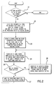
- Fig. 2 is a flowchart showing a processing flow for conversion processing to color an electronic filing document file.
- the processing control section 2 determines whether a document file is present in the input file storage section 1. If step 21 is negative, the processing is ended.
- step 21 the operation flow advances to step 22, where the processing control section 2 selects a document file stored in the input file storage section 1, and moves the selected document file to the processing object file holding section 6.
- the document file is thus moved to the processing object file holding section 6, and is the "processing object file”.
- step 23 the processing control section 2 controls the character color definition inserting section 8 to define a color designation, after color conversion, to the color table of processing object file in the processing object file holding section 6.
- step 24 the processing control section 2 controls the mark control term detecting section 3 to determine if a control term corresponding to the mark is present in the document file of the processing object file.
- step 25 a determination is made whether the control term was detected by the search.
- step 25 If step 25 is affirmative, the operation flow advances to the step 26, where the mark control word substitute section 9 substitutes the detected control term with a color designating control term.
- the operation flow then returns to step 24, and continues processing for the next control term in the processing object file. In other words, the processing searches for the next control term, and where a control term is detected it substitutes the control term with a color designating control term, in steps 24 through 26. These steps are repeatedly performed as needed.
- step S25 If the answer in step S25 is negative, all of the processings for the control terms have been completed. Thus, in step 27, the processing object file is moved to the output file storage section 5 and stored therein. The operation then returns to step 21, and repeats the processing as needed.
- an electronic filing document file of black and white documents can be read.
- a control term that indicates the addition of a highlight representation mark in a black and white document, such as underline, can be detected.
- the mark itself can be erased, marked character string can be colored, and a colored electronic filing document file can be output.
- correlation of mark control term with character color is defined by a data set in a mark control term/character color correspondence table 30 (Fig. 3).
- a mark control term/character color correspondence table 30 Fig. 3
- an underlined character string is converted to a red character string of red color free underline
- a character string with hatching with 20% density dots is converted to a character string of red color free hatching
- a character string with hatching with a backward diagonal background pattern is converted to a character string of blue color free hatching.
- a marked black and white data can be converted to color document data.
- the input file storage section 1 is linked, for example by a network, to another document processing system through the external network bus 11.
- the input file storage section receives RTF files transmitted from another document processing system, and stores black and white RTF files that will be converted to color documents.
- the input file storage section 1 is used to store plural RTF files and perform coloring processing in a group.
- the processing control section 2 controls the conversion processing for coloring and also controls individual system components.
- the processor control section 2 can read an electronic filing document file that contains layout information, can detect a highlight mark, such as underline, can colorize the marked character string and can output a colored file.
- the processing object file holding section 6 holds a document file as a processing object file.
- the processing object file holding section 6 holds an RTF file, hereinafter known as "processing object file” for a document file to be converted to a color document.
- Data conversion to a color document is conducted for held processing object files.
- a file is held in the processing object file holding section 6.
- the mark control word detecting section 3, character color definition inserting section 8 and mark control word substitute section 9 access the held processing object file, can perform the data conversion to a color document, and can alter the file contents.
- the output file storage section 5 stores an RTF file after the conversion.
- the output file storage section 5 can store document files for a plurality of RTF files. It can be linked to another document processing system by the external network bus 11, for example, by a wire. When another document processing system accesses the document processing system, the stored RTF files, after coloration conversion, are delivered to the accessed processing system from the output file storage section 5.
- a mark control term or word/color correspondence table holding section 7 holds tabulated data as a mark control word/color correspondence table 30, i.e., as in Fig. 3.
- the table 30 includes tabulated data correlating control terms that indicate the addition of marks in black and white documents, RGB values of character colors, and color table indexes for the processing object file.
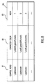
- Fig. 3 is a diagram explaining a data structure for a mark control word/color correspondence table 30.
- the mark control word/color correspondence table 30 comprises a control term or word field 31 (hereinafter control word field), a character color field 32 and an index field 33.
- Color designation entry data can be stored data correlating mark control terms and character colors with each other. In other words, one entry data in table 30 correlates a control term indicating the addition of one mark with a color designation.
- the control word field 31 stores control terms indicating marks for conversion to colors.
- the character color field 32 describes RGB definitions for the color table corresponding to the marks indicated by the values of "control terms” at the same lines or entries in the control word field 31.
- the color designation value ";" in the character color field 32 indicates a default value.
- the index field 33 stores a color table index for the processing object file, whose index is coincident with the value of "character color" at the same line or entry as the character color field 32.
- a corresponding color designation exists as a corresponding color designation value in the character color field 32.
- An indirect color designation can be made using a corresponding index value in the index field 33, and by utilizing the color table.
- the mark control word/color correspondence table 30 is prepared based on conversion or color designation, where data conversion for the coloration of a black and white document was conducted.
- the control term values in the control term field 31 and values of color table RGB are defined as character colors in the character color field 32 and are fixed.
- the index values in the index field 33 change for each processing of an object file.
- the correlation data using each entry data in the mark control word/color correspondence table 30 are accessed by the character color definition inserting section 8 to set a color to be used in the document, after the coloration conversion in the document file.
- the table 30 is also accessed by the mark control word detecting section 3 to determine a control term corresponding to the mark concerned from the document file.
- the correlation data can be accessed by the mark control word substitute section 9 to substitute a control term in the document file with a color designating control term.
- Processing for setting a character color in the color table of the processing object file for use in the document after the coloration conversion is performed in the character color definition inserting section 8. Also, a processing, where an associated index of the color table for the processing object file, for setting in the index field 33 of the mark control word/color correspondence table 30 held by the mark control word/color correspondence table holding section 7.
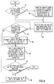
- Fig. 4 is a flowchart showing processing in the character color definition inserting section 8. With reference to Fig. 4, a description is now provided for processing by the character color definition inserting section 8 to set the character color in the document after the coloration conversion in the color table of the processing object file.
- step 41 determines whether a color table declaration is present in the processing object file. If a color table declaration is not present, the operation advances to step 42, where character string ⁇ ⁇ colortbl; ⁇ is inserted into a header portion of the processing object file at a location to satisfy grammar in the RTF specification. If a color table declaration is present, the operation advances to step 43.
- step 43 a first line or entry is chosen from the mark control word/color correspondence table 30 held by the mark control word/color correspondence table holding section 7. This is stored as the current line.
- step 44 a determination is made whether a value of "character color" in the character color field for the current line is in the color table for the processing object file.
- step 45 If the value of that "character color” is not in the color table for the processing object file, the value of "character color” in the current line character color field 32 is added to a last part of the color table of the processing object file, in step 45. The operation advances to step 46. If in step 44 the value of "character color” in the character color field 32 of the current line is in the color table of the processing object file, the operation advances directly to step 46.
- Step 46 determines the number of the color table for the processing object file and the value of "character color" in the character color field 32 occurs. The associated index is then written in the current line as a value in the index field 33. The operation then moves to the step 47, where a determination is made whether the current line is the last line or entry of the mark control word/color correspondence table 30. If step 47 is negative, the line next to the current line is stored as a new current line in step 48. The operation returns to step 44, where an operation from step 44 is repeated.
- the operation is ended. This is because all character color definitions in the table 30 have been stored for the processing object file up to this point.
- the mark control word detecting section 3 will now be described.
- a control term which is coincident with a value designated in the control word field 31 for the mark control word/color correspondence table 30, is searched and detected for the processing object file.
- the detected control term and its position in the processing object file are then stored.
- the number of control term(s) detected by a single search should not be larger than one, and detection of "0" indicates that a processing object file does not contain control term as designated in the control word field 31.
- Such a mark control term detecting function detects a character from the processing object file during processing of the leading character detecting section 4. It is also utilized to replace a mark with color during processing of the mark control word substitute section 9.
- the leading character detecting section 4 searches a processing object file to detect the first character after a certain control term from text contents of a document in the processing object file.
- the leading character detecting section 4 then stores the detected character and its position in the processing object file.
- Control terms stored in the mark control word detecting section 3 are used as the control term corresponding to a search start point and position. Processing in accordance with the invention then is started.
- the leading character detecting section 4 can substitute a mark with color during processing of the mark control word substitute section 9.
- the mark control word substitute section 9 can delete a control term indicating an addition of a mark from a processing object file.
- the mark control word substitute section can also insert a color designating control term into the processing object file.
- Fig. 5 is a flowchart for processing in the mark control word substitute section 9.
- step 51 a search is made for a line of the control word field 31 in the mark control word/color correspondence table 30 that is held in the mark control word/color correspondence table holding section 7.
- a line where the value of the control term coincides with the control term value stored in the mark control word detecting section 3, is then selected and stored as the current line.
- the operation advances to step 52, where a color designating control term is stored as a control term.
- the control term can comprise character string " ⁇ cf" and an index value for the index field 33 of the current line following the character string.
- step 53 a determination is made whether the control term stored in the mark control word detecting section 9 is positioned in a header portion of the processing object file. If yes in step 53, the operation moves to step 54, where a control term, which stored in the mark control word detecting section 3, is deleted from the processing object file and a color designating control term prepared in step 52, is inserted into the deleted position. The operation is then ended.
- the leading character detecting section 4 detects a character and its position. More specifically, the leading character detecting section 4 can search the processing object file, detect the first character after the control term from the text contents of document in the processing object file, and store both the detected character and its position in the processing object file.
- step 56 the detected character and its position are accessed.
- the control term stored in the mark control word detecting section 3 is deleted from the processing object file, and a color designating control term, which was prepared in step 52, can be inserted before the position of the character detected by the leading character detecting section 4. This terminates operation.
- Values in the mark control word/character color correspondence table 30 are set, for example, in Fig. 3, as a description '... ⁇ ⁇ stylesheet ⁇ bgbdiag; ⁇ ... ' and can be substituted for by a description '... ⁇ ⁇ stylesheet ⁇ cf2; ⁇ ... ' by the mark control word substitute section 9. If a description '... ⁇ ⁇ ul underline ⁇ ul0 is drawn at a portion ⁇ ... ' is in a document of the processing object file, this description is substituted for by the description '... ⁇ ⁇ cfl underline ⁇ cf0 is drawn at a portion ⁇ ...'.
- marked black and white data can be converted to color document data using an electronic filing document file converter as a document processor according to the first embodiment.
- an underlined character string can be converted to a red character string free of an underline
- a hatched character string with 20% density dots can be converted to a red character string free of a hatching.
- a hatched character string with a backward diagonal background pattern can be converted to a blue character string free of a hatching.
- a mark or a control term representing a mark indicates a highlighted portion of a black and white document.
- the control term provides attributes for a character string or a paragraph.
- a mark for color conversion is provided as graphic information.
- a mark could be, for example, a closed curve drawn on a page of a document. This is used as geometric graphic or bit map image data.
- a page layout is calculated, and a comparison is made between a position of a character string and that of a mark so as to detect a marked character string.
- geometric graphic data can be provided as drawn or drawing objects. More specifically, the description of a certain drawing object can be expressed as: ' ⁇ ⁇ *' ⁇ do ⁇ dohead ⁇ ⁇ dpinfo ⁇ ' ⁇ '. where, both " ⁇ dohead ⁇ " and “ ⁇ dpinfo ⁇ ” are nonterminals. " ⁇ dohead ⁇ ” contains a description relating setting of an anchor or the drawing object. " ⁇ Dpinfo ⁇ ” contains a description relating to a shape of the drawing object. Further, control terms defined by the RTF specification are used for the description of a shape, such as line type or a solid print pattern.
- bit map image data can be provided as pictures and expressed by a description, for example beginning with control term " ⁇ pict".
- control term ⁇ pict
- bit data of hexadecimal or binary digit representation can be provided.
- color conversion processing is performed using terms that are provided as graphic information, by means of the electronic filing document converter according to the second embodiment.
- Fig. 6 is a block diagram illustrating system components comprising the electronic filing document converter used as a document processor according to the second embodiment.
- the document processor comprises an input file storage section 1, an output file storage section 5, a processing object file holding section 6, an internal bus 10, an external network bus 11, a mark control word/color correspondence table holding section 60, a processing control section 61, a mark graphic detecting section 62, a marked character detecting section 63, a font holding section 64, a character color definition inserting section 65, a color designating control word inserting section 66, a page layout calculating section 67, and a mark graphic deleting section 68.
- the input file storage section 1, output file storage section 5, processing object file holding section 6, mark line type/color correspondence table holding section 60, processing control section 61, mark graphic detecting section 62, marked character string detecting section 63, font holding section 64, character color definition inserting section 65, color designating control word inserting section 66, page layout calculating section 67 and mark graphic deleting section 68 are connected with one another through the internal bus 10 as in the first embodiment.
- these constitute a document processing system of terminal equipment for a network system.
- the document processing system is connected via the external network 11 to an external document processing system that can be connected to a network system.
- color conversion processing for an electronic filing document is performed using a graphic information mark.
- the processing control section 61 while controlling other system components, can also read a file for the electronic filing document containing the graphic information as a mark, can color characters of a character string specified by using a closed curve drawn on a page, identify geometric graphic data or bit map image data as a mark, can erase the mark itself, and can output the converted file as a colored electronic filing document.
- a color processing for an electronic filing document can be performed so a character string enclosed by a bit map image can be converted to a red character string, a character string enclosed by a broken line can be converted to a green character string, and a character string enclosed by a dotted line can be converted to a blue character string.
- Fig. 7 is a flowchart for the processing flow of the conversion processing to color of an electronic filing document by the processing control section according to the second embodiment. The processing flow will now be described.
- the processing control section 61 determines whether document files are present in the input file storage section 1. If the answer in step 71 is no, processing is ended.
- step 71 If files are present in the input file storage section 61, i.e., yes in step 71, the operation advances to step 72.
- the processing control section 61 selects one document file from the input file storage section 1. This selected file can be moved to the processing object file holding section 6, as a processing object file.
- step 73 the character color definition inserting section 65 defines a color designation after color conversion to the color table for the document for the processing object file.
- step 74 the page layout calculating section 67 calculates a page layout for the processing object file, followed by storing or holding of the calculation result.
- step 75 the mark graphic detecting section 62 can detect all drawing objects and pictures that correspond to marks contained in the processing object file. Their positions in the file are then stored.
- step 76 the marked character string detecting section 63 detects all marked character strings contained in the processing object file, and their positions in the file are stored.
- step 77 the color designating control word inserting section 66 inserts color designating control terms according to mark line types before and/or after all the marked character strings, and stores them in the processing object file.
- step 78 the mark graphic deleting section 68 deletes all drawing objects and pictures corresponding to marks from the processing object file. Thus, the processing for the electronic filing document is complete.
- step 79 to continue, the processing object file is moved to the output file storage section 5, and a processed document file is stored in the same storage section. Then, the operation returns to step 71 and repeated.
- the processing control section 2 while controlling the other system components, can read an electronic filing document file for black and white documents that contain layout information, can detect a control word indicating an addition of a highlight representation mark in each black and white document, such as underline, can erase the mark itself, can color the marked character string, and can output the colored electronic filing document file.
- color conversion processing can be conducted.
- the color conversion processing can be, for example, performed by series of operations in the processing control section 61. These operations include converting a character string enclosed by a bit map image to a red character string, converting a character string enclosed by a graphic form of broken line to a green character string, and converting a character string enclosed by a graphic form of dotted line to a blue character string.
- black and white document data with graphic information as marks can be converted to color document data.
- Fig. 8 is a diagram explaining the data structure of the mark line type/color correspondence table 80.
- the mark line type/color correspondence table 80 comprises a control term or word field 81 (hereinafter control word field 81), a character color field 82 and an index field 83.
- Entry data for color designation can be stored data correlating control terms for graphic information as marks with character colors. In other words, entry data in the mark line type/color correspondence table 80 correlates control terms for graphic information as marks with color designations for color characters.
- Control terms representing marks for conversion to colors are stored in the control word field 81.
- Stored control terms designate the line type or style of objects.
- character color field 82 similar to the mark control word/color correspondence table 30 of the first embodiment, character colors after color conversion are described with RGB definitions for a color table corresponding to the marks indicated by the values of control terms at the same lines or entries in the control word field 81. Color table indexes are coincident with values of character colors at the respective lines or entries in the character color field 82.
- a control term representing graphic information as a mark (e.g.
- a direct color designation can be made using a corresponding value of color designation in the character color field 82.
- An indirect color designation can be made using the corresponding index value in the index field 83. Both the direct and indirect color designation utilize the color table.
- the mark line type/color correspondence table 80 is prepared based on contents of conversion, i.e., color designation for coloring of a document character string using graphic information as marks.
- control term values in the control word field 81 and values of color table RGB definitions are fixed, index values in the index field 83 can be changed for each processing object file.
- Correlation data using each entry data in the mark line type/color correspondence table 80 is accessed by the character color definition inserting section 65 and set in the document file the color. It is used in the document after the color conversion. They are also accessed by the mark graphic detecting section 62 for determining the control term corresponding to a pertinent mark from the document file. The correlation data are further accessed by the color designating control word inserting section 66 to insert a color designating control term into the character string specified by the mark in the document file.
- the character color definition inserting section 65 processing to set a color table for the processing object file character color for use in the document after the coloration conversion is conducted. Also, an index in the color table is set in the index field 83 of the mark line type/color correspondence table 80 held by the mark line type/color correspondence table holding section 60. Since processing of the character color definition inserting section 65 is similar to a processing illustrated in Fig. 4, provided that RGB values defined here there are those in the table 80 held by the table holding section 60, an explanation is omitted.
- the font holding section 64 holds a character font that can be designated by a font table group at the header portion in the processing object file.
- the page layout calculating section 67 utilizes character font information held in the font holding section 64 to make a rough page layout calculation.
- the marked character string detecting section 63 accesses the character font information held in the font holding section 64 to detect a character string within a graphic information mark.
- the page layout calculating section 67 can calculate areas occupied by a paragraph and drawing object(s) and picture(s) in the processing object file on a page, and can store the calculation results as data in a coordinate system for each page.
- a coordinate system with a left upper corner point of each page as the origin, an upper end of the page as an x axis and the left end of the page as a y axis is created.
- the coordinate system uses a unit "twip", which indicates a length on the page layout. In terms of point, which is a unit used in printing, one twip corresponds to 0.05 point.
- An area paragraph is given as a minimum rectangular area that is capable of including all text contents when the text contents are laid out on a page. Calculation for this area uses information relating to the size of the character font held in the font holding section 64. A result of this calculation is stored as rectangular data on the coordinates. The position in the processing object file where a description of the paragraph starts is stored correlating to rectangular data.
- a drawing object area is given as a minimum rectangular area capable of including relevant graphic form(s).
- a result of this calculation is stored as rectangular data on the coordinates.
- the position in the processing object file, where a description of the drawing object is started, i.e., the position of the control word " ⁇ do" is stored correlating to the rectangular data.
- a picture area is given as a minimum rectangular area that is capable of including relevant bit map image(s).
- the page layout calculating section 67 holds results of the layout calculations. Positional relations between such document data in the processing object file and data in the page coordinate system are shown in Fig. 9.
- Fig. 9 explains relationships between document data in the processing object file and areas that the document data occupy on a page.
- a description of a character string corresponding to the area of paragraph that is started by the control term " ⁇ par” so a paragraph area calculated by the page layout calculation and a start point of description starting with control term " ⁇ par”, are stored with each other.
- other rectangular areas which are calculated by the layout calculation and control terms as description start points corresponding to those areas, are stored with each other.
- mark graphic detecting section 62 searches for a processing object file and detects drawing object(s) and picture(s) corresponding to marks specifying a character string to be colored.
- the areas designated by marks can overlap an area of a paragraph on a page.
- the mark graphic detecting section 62 searches for such drawing object(s) or picture(s) using the page layout calculating section 67.
- drawing object(s) and picture(s) corresponding to marks are detected by performing a series of the following Processing Steps (1) to (3) for all descriptions of drawing object(s) and picture(s) in each processing object file.
- the marked character string detecting section 63 detects a character string in paragraph marked with the drawing object(s) or picture(s). More specifically, for each description start position stored in the mark graphic detecting section, the marked character string detecting section 63 performs Processing Steps (10) to (13). These steps detect a character string in paragraph marked with the drawing object or picture. Processing Step (10): Search for area data for the paragraph using the page layout calculating section 67, from a description start position for the paragraph stored in the mark graphic detecting section 62.
- the marked character string detecting section 63 detects the character string in the paragraph marked with the drawing object(s) or picture(s).
- the color designating control word inserting section 66 inserts color designating control terms.
- control terms for changing the color of the marked character string are inserted into a processing object file corresponding to a position in the character string. More specifically, control terms for color designation are inserted just before and just after the first and last characters, which are marked and stored in the marked character string detecting section 63.
- a value for the control term inserted just before the first character's position is determined using the mark line type/color correspondence table 80 in the mark line type/color correspondence table holding section 60.
- the particular line or entry data for the table 80 is determined by the description of the drawing object(s) or picture(s), which is associated with the first character position.
- the mark graphic deleting section 68 deletes the graphic information that was utilized as a mark.
- the mark graphic deleting section 68 accesses the mark line type/color correspondence table 80 held in the mark line type/color correspondence table holding section 60, and deletes arbitrary descriptions of drawing object(s) or picture(s) from the processing object file.
- a character color value 'Red " ⁇ red255 ⁇ green0 ⁇ blue0"' is set for the control word " ⁇ dplinesolid”; the character value 'Green: “ ⁇ red0 ⁇ green255 ⁇ blue0”' is set for control term “ ⁇ dplinedash”; and the character color value 'Blue: “ ⁇ red0 ⁇ green0 ⁇ blue255”' is set for control term " ⁇ dplinedot”.
- Color conversion then is conducted. This results in a character string enclosed with a bit map image being colored red, a character string enclosed with a graphic form of broken line being colored green, and a character string enclosed with a graphic form of dotted line being colored blue.
- graphic information as drawing object(s) or picture(s) can be utilized for color conversion of characters in a character string.
- a mark control term as underline or hatching is utilized, as a mark, for color conversion of characters in a character string.
- color conversion methods are of the first and second embodiments are independent of each other. However, it is possible to combine the methods of the first and second embodiments to conduct color conversion of various electronic filing documents. In particular, the first and second embodiments can be used even if an entire system and its system components are modified. For example, by combining an electronic filing document file converter, according to the first embodiment, with the electronic filing document converter, according to the second embodiment, it is possible to process both marks using text attributes and marks based on picture(s) or drawing(s), to color characters of a character string.
- the input file storage section 1 may comprise a format conversion function to convert an arbitrary file format to RTF format. It is possible to color convert a document file of an arbitrary file format.
- the output file storage section 5 may comprise a format conversion function to convert from an RTF format to an arbitrary file format with a color describing capability.
- a document file, which has undergone the color conversion processing can be output in an arbitrary file format.
- the format conversion function may comprise a function that permits the user to select a desired file format and to receive an output in a file format that a user desires.
- the tables in the mark control word/color correspondence table holding section 7 and the mark line type/color correspondence table holding section 64 may be modified by a user. Thus, it is possible to set a mark-color correlation to one desired by a user. Further, an inquiry can be made by a user whether any alteration is temporary or permanent. Thereafter, an alteration may be set based on instructions given by a user, so correlation alteration can meet a user's request.
- GUI Graphic User Interface
- This may be in addition to a structure that permits direct input of the values of various data in the mark control word/color correspondence table 30 and mark line type/color correspondence table 80. It is thus possible to reduce a burden on the user's input operation.
- the tables can be optionally replaced or updated.
- an item field for a catalog of control terms relating to the character shape for example, relating to character shape for character format characteristics, such as " ⁇ i", " ⁇ outl", may be added to a correspondence table held by the mark control word/color correspondence table holding section 7 or the mark line type/color correspondence holding section 64.
- Associated values in the item field are written after color designating control terms when writing the control terms into the processing object file. Therefore, it is possible to alter color and character shape of a marked character string. It is also possible to alter the shape of the character background area, i.e., modifications can be made to permit hatching, netting and the like.
- contents of the character color designating control terms may remain substantially unchanged.
- a color conversion involving conversion of mark control terms for the characters of a character string a modification where the conversion of character shape control words is done instead of a conversion of color designating control words. This is advantageous because a user can obtain a desired highly conspicuous document with less expense, when the discriminating effect is ensured without a change of color.
- first and second embodiments use lines and hatchings for specifying characters of a character string in color conversion, other marks may be used. These marks must permit a visual specifying of covered area(s), such as parentheses, brackets, and solid print.
- a modification is also possible to alter contents of visual characteristic based on color of mark.
- the mark control word detecting section or the mark graphic detecting section can detect a specific color as a mark.
- the alteration contents are determined from the detected mark color based on a mark control word/color correspondence table or a mark line type/color correspondence table. Also, information that relates the mark's shape and color with the character string altering method can be held by the respective table. Thus, a configuration of the contents for the color designating control terms for characters in the specified character string can be altered.
- a visual characteristic of a character string can be altered according to the shape of mark in the first and second embodiments, it is possible to alter visual characteristic using characters or graphics located near the mark. For example, in an electronic filing document file converter according to the first embodiment, it is possible to search for a control term for superscript or subscript present just before or just after the control term corresponding to a mark. If it found, a visual characteristic of the marked character string can be altered.
- the sales of company A are by far the most important.
- ...' can be described as '...
- the sales of company A are ⁇ ul by far the most ⁇ ul0 ⁇ sub important ⁇ nosupersub. ⁇ ... '.
- the control term " ⁇ sub" indicates the start of subscript, while the control term " ⁇ nosupersub” indicates the end of superscript or subscript. Therefore, a search is conducted for a control term and control term substitute for altering its visual characteristic.
- control word conversion processing for the character string can be performed.
- information pieces which correlate a shape of mark to be detected and characters or graphics near the mark with an alteration method for the character string, are held according to a file format of processing data in the mark line type/color correspondence table.
- the data conversion processing is then conducted based on those information pieces.
- the mark graphic detecting section 62 searches for picture elements near the mark to recognize characters or a graphic form. Based on both a result of this recognition and correlation information in the mark line type/color correspondence table, the color designating control word inserting section 66 inserts control terms into the processing object file.
- the mark graphic deleting section 68 changes a color of the mark graphic and character(s) or graphic(s) into white. A change of visual characteristics in the character string can then be obtained.
- RTF is used as a file format for processing data.
- any other suitable file format may be used, as long as it has a describing capability equal to or higher than that of RTF, with respect to color and mark.
- both converters use a table form for a data structure in the mark line type/color correspondence table, any other data structure may be used, as long as it permits a color description with control terms as keys. Thus, modifications may be made for various formats and data structures.
- a description of a copying machine with edit function as a document processor according to a third embodiment of the invention is now provided.
- the electronic filing document converter according to the second embodiment used graphic information pieces as marks for the color conversion. For example, closed curves drawn on document pages, as well as those described as geometric graphic data or bit map image data in files, were utilized as marks when a marked character string was detected.
- a marked character string is detected by an image data processing. Color conversion for characters of the character string in an original document is then performed.
- the copying machine with edit function according to the third embodiment permits a black and white original marked with a colored marker pen to be read. A mark can be detected, and a colored original with colored characters for the marked character string can be output. Further, a change in color of characters in a character string can be made based on a color of the colored marker pen.
- a user is first required to mark, for example with line or parentheses, each black and white original portion to be colored.
- a user can color or paint an entire portion, using a colored marker pen, to provide a mark.
- the colored marker pen can be any appropriate colored marker pen.
- a user can use different colors "for heading” or "for highlight”.
- the user can mark a portion of a black and white original to be colored by a marker pen to suit the intended purpose.
- the user can put the marked black and white original on an original reading section of the copying machine with an edit function.
- the user then pushes a start button that initiates a processing control section (described hereinafter) so a converted color original can be output with the marked portion as the desired color.
- Fig. 10 is a block diagram showing system components that form a copying machine with edit function according to the third embodiment.
- the system comprises an internal bus 100, an original reading section 101, a processing control section 102, a mark graphic detecting section 103, a mark area detecting section 104, an original output section 105, a processing image data holding section 106, a mark-color correspondence table holding section 107, a character image color changing section 108, a mark image deleting section 109, and a marking section 110.
- the copying machine with an edit function comprises system components that form processing components for image data or pixel data. These components are similar to the image data processing system components of the document processor according to the second embodiment. More specifically, in the system configuration according to the third embodiment, the original reading section 101, processing control section 102, mark image detecting section 103, mark area detecting section 104, original output section 105, processing image data holding section 106, mark-color correspondence table holding section 107, character image color changing section 108, mark image deleting section 109, and marking section 110 are all connected with one another through an internal bus 100 to form a single copying machine with an edit function as a document processing system.
- a mark from a colored marker pen made on a black and white original document is detected.
- a conversion processing for coloring the original document is then performed.
- the processing control section 102 while controlling the other system components, reads the black and white original that is marked with the colored marker pen, discriminates the character string specified with the mark, colors the character string, erases the mark itself, and outputs a colored original document.
- Fig. 11 is a flowchart showing the processing color conversion process for an original document by a processing control section 102 according to the third embodiment.
- step 113 the processing control section 102 controls the mark image detecting section 103 to determine whether all pixel data tuples corresponding to one mark are present in the processing image of the processing image data.
- step 114 a determination is made judgment whether one pixel data tuple was detected in step 113. If yes, the operation advances to step 116, where the processing control section 102 controls the mark area detecting section 104 to determine if a pixel data tuple is positioned inside the detected mark.
- step 117 the character image color changing section 108 changes the value of black data for the image data positioned inside the mark into corresponding character color based on a mark-color correspondence table. More specifically, the value of black data in the image data positioned inside the mark can be changed to a value for a character color associated with the colored marker pen based on a mark-color correspondence table.
- step 118 the mark image detecting section 109 alters the processing image so a marked image is not displayed during output of the original.
- the color designated for the mark image is changed to the same color as the background image color. Then, for processing of the next pixel data tuple, the operation returns to step 113, and is repeated.
- step 114 determines that a pixel data tuple has not been detected, the processing for the pixel data in the original document is ended.
- the operation moves to step 115, where the original output section 105 outputs a designated number of copies of the original, with the processing image data printed thereon.
- the processing control section 102 while controlling the other system components, can read an original image from a black and white document, can detect characters, i.e., pixel data for a character string marked with a colored marker pen, can color characters, can erase the mark, and can output the colored image of the original document after printing.
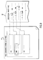
- Fig. 12 is a diagram illustrating and explaining the structure of image data read by the original reading section 102.
- the original reading section 102 optically scans a black and white original 121 as a processing object, makes a resolution into the three primary colors of light R (red), G (green) and B (blue), produces a digital color image data 122 with 256 gradations (8 bits) using the respective colors. It then holds the digital color image data in the processing image data holding section 106.
- the digital color image data corresponds to 0.0625 mm square (16 x 16 picture elements per mm 2 , resolution, about 400 dpi) in the original.
- One pixel data is represented by 24 bits (continuous 3-byte data).
- the first 8 bits of 24 bits represent 256 gradation data of R (red)
- the next 8 bits represent 256 gradation data of G (green)
- the last 8 bits represent 256 gradation data of B (blue).
- Digital color image data obtained by a single scan correspond to one A4-size original sheet, and are represented by 3360 x 4752 pieces of continuous pixel data.
- the pixel data order is determined from the left top position on the original.
- This data sequence conforms with an optical scan, so a scan line (realized by a CCD) along a short side direction of the original is moved along a long side direction.
- pixel data from the head to the 3360th pixel are top pixels arranged from left to right. In this way, 4752 tuples of pixel data are arranged from top to bottom, with 3360 pixel data as one tuple.
- the processing image data holding section 106 holds digital color image data, i.e., processing image data as a processing object when the date has been read by the original reading section 101.
- the processing image data on one sheet of an A4-size original has a size of 3360 x 4752 x 24 bits, corresponding to a data volume of about approximately 46 Mbytes.
- the mark-color correspondence table holding section 107 comprises a mark-color correspondence table.
- the mark-color correspondence table represents tabulated conversion data, similar to the mark control word/color correspondence table 30 (Fig. 3), where data correlate colors of marker pens (hereinafter "marker color”) with character colors used in output originals.
- the color values in the mark-color correspondence table are presented as pixel data.
- a marker color can be initially subjected to colorimetry, and then converted to pixel data.
- the pixel data can be defined in the mark-color correspondence table.
- the range of values detected and falling under an allowable range of marker colors is also defined in the correspondence table.
- the mark image detecting section 103 accesses the range of value(s) detected as a mark within the allowable range in the correspondence table, and detects image or pixel data corresponding to the mark. Further, the character image color changing section 108 accesses the character color value in the correspondence table, where the color is used in the outputted original. The character image color changing section 108 also alters the color of pixel data that correspond to marked characters.
- the mark image detecting section 103 detects the marker color on the black and white original document.
- the mark image detecting section 103 detects one tuple of pixel data corresponding to the mark and stores the pixel data tuple.
- the pixel data tuple corresponding to the mark indicates a continuous pixel data group on the original having the same marker color.
- the detected pixel data tuple is stored as a set, hereinafter referred to as "mark pixel set", with pixel data addresses as elements.
- the pixel data tuple is stored while controlling addition of elements to avoid overlapping of elements. In other words, all the addresses or elements are different from one another.
- the processing in the pixel data storing mechanism is performed based on an algorithm (the algorithm may be a recursive algorithm) for processing steps (21) to (26) as follows:
- the mark area detecting section 104 utilizes mark image detecting section 103 to detect picture elements located inside a mark. It also utilizes the character image color changing section 108 to determine a marker color for a mark. It further utilizes the mark image deleting section 109 to alter the color of image data corresponding to a mark.
- Fig. 13 is a diagram illustrating an address pair of pixel data detected as mark area by the mark area detecting section 104.
- the mark area detecting section 104 detects two picture elements inside the pixel data of mark detected by the mark image detecting section 103, and stores the addresses.
- pixel data addresses detected as a mark area, and stored by the mark area detecting section 104 indicate an address range of the pixel data as a mark area.
- a pair of elements is detected indicating an address start point (address L) and an address end point (address R) for digital color image data 132 at every scanning line.
- a set, including that pair of elements, is stored.
- the address pair, address L and address R, for each pixel data corresponds to a portion of an associated scanning line, i.e., a portion of 3360 picture elements arranged in the short side direction of the original.
- Address L of the picture element is located in the left most position and address R of the picture element is located in the rightmost position in each scanning line.
- Those addresses along with other addresses are searched included in the mark pixel set stored in the mark image detecting section 103. Both addresses are determined to be paired at every scanning line. Thus, a mark area is detected at every scanning line.
- the character image color changing section 108 changes the associated character color based on the mark-color correspondence table.
- an object color of a mark that is detected and stored as a mark pixel, and set by the mark image detecting section 103 is then changed into the associated character color based on the correspondence table.
- the mark image deleting section 109 deletes the image corresponding to the mark from the processing object image.
- a mark attached to the black and white original may not appear in the resultant color document. If values for all pixel data that the mark pixel set stored in the mark image detecting section 103 to indicate a white color change, i.e., all the 24 bits are "on”, processing image data capable of printing is obtained.
- processing image data are sent to the original output section 105, which in turn, outputs a colored original after printing.
- the original output section 105 may comprise a laser beam or other similar device.
- the original output section 105 converts the processing image data, after the coloration conversion represented by RGB into the data of Y (yellow), M (magenta), C (cyan) and K (black), to toner colors for color-printed copies. Since the color copying machine, according to this third embodiment, requires a development cycle for each toner color YMCK, data corresponding to the associated toner color for every development cycle can be used.
- the processing control section 102 controls the original output section 105 to copy the colored original on sheets designated by a user.
- the marking section 110 comprises a marking function for specifying coloration conversion of a black and white original, which was read by the original reading section.
- a black and white original can be displayed on a display screen and marked with a light pen, stylus pen of a pointing device or similar device.
- a pointer cursor such as a mouse, can also be used.
- a portion to be subjected to a color conversion can be specified.
- the portion of the black and white original for the color conversion may be directly marked with a colored marker pen without electronic marking.
- the color of the colored marker pen should be previously cataloged in the system, i.e., in the mark-color correspondence table.
- plural colored marker pens of different colors can be provided.
- the colors of the marker pens for color conversion and the colors for color conversion can be coordinated with each other, according to use, i.e., "for heading" and "for highlight.”
- the processing control section 102 further controls the entire control processing for the copying machine with edit function.
- the control section 102 can receive instructions from a user concerning the number of copies to be output, can start copying, and can execute processing related to color copying.
- the processing control section 102 may include a user interface processing function and structure through buttons, a touch panel or similar interactive device.
- the mark image detecting section 103 can recognize symbols/numerals/characters that are written with a marker pen near a mark.
- the contents of the mark-color correspondence table in the mark-color correspondence table holding section 107 are modified to set correlations between recognized symbols/numerals/characters and coloration colors for black and white originals. This permits the use of a single-colored marker pen, without plural colored marker pens.
- the mark image deleting section 109 can delete recognized images of symbols/numerals/characters. Thereby, it is possible to change a color of a marked character string based on symbols near the mark. For example, if symbols, such as o ⁇ ⁇ ⁇ , numerals, or characters, such as "important" or "highlight,” are written with a marker pen near a mark of a to be colored portion of a black and white document, it is possible to obtain a colored original with colored characters for the marked portion.
- the color correlation in the mark/color correspondence table held by the mark/color correlation table 107 can also be altered for correlation of marker color, character color and background color.
- the character image color changing section 108 can change the value of background color with respect to all the pixel data present in the mark pixel address range, except black.
- the system component of the mark image deleting section can be removed.
- the color of the marked character string can be changed, and if desired, at the same time, a colored original can be output so the marked area is colored. Since the character color and background color change, it is possible to properly color the document. Since the handwriting with a marker pen is in a character background portion, it is easier for a user to get a document with a higher appealing effect.
- a hatching pattern can also be changed in addition to a change of color as above.
- the colors correlation defined in the mark/color correspondence table held by the mark/color correspondence table holding section 107 can include a master pattern for the background color area.
- the color of the character background area can be partially altered based on the master pattern. Lines such as ⁇ , /////,
- the color of the background area may remain because it is possible to obtain distinct character strings without altering the background area color.
- a further modification can be made in the original output section 105 to output in black and white.
- the original document can be output through a single development using an appropriate toner color during printing of characters. As a result, it is possible for a user to obtain less expensive original, which is hatched to permit easier distinction.
- An enclosed line or solid paint can be used as a mark in another modification.
- any other graphic form may be used if it visually specifies the area to be colored, i.e., such as parentheses, brackets or underline.
- a mark or underline 141 is added under a specified character string.
- a search is made for a white pixel area corresponding to a line spacing through line spacing just above the underline 141.
- the area 143 between the underline 141 and the area 142 is the colored area.
- the width of each area 142 and 143 is equal to the length of the underline 141. Its height corresponds to a certain number of picture elements for each line spacing.
- a parenthesis 153 or a bracket 154 faces a specific direction when used as mark.
- the direction is determined whether end-point pixel data 151 in the parenthesis or bracket that constitutes pixel data and a central pixel data 152, is positioned on the right side or left side, in a scanning direction. This specifies a mark range.
- the parenthesis and bracket used as a mark are right-hand marks. Thus, determining left-hand marks can determine a character area of a character string positioned therebetween.
- color alteration is performed for pixel data that constitutes characters in a marked area.
- a modification may be made to alter the character shape, to move a bit and invert a bit based on logic operations for picture elements. For example, it is possible to thicken or thin characters, make characters into pouched characters, and shaded features of the picture elements.
- the character color may remain unchanged, if character strings can be distinguished without changing character color.
- processing image data can be stored in a compressed state. This is advantageous because the volume of data held by the processing image data holding section 106 can be decreased, and a volume of data checked by the mark image detecting section and mark area detecting section can become smaller. This permits the processing to be executed more rapidly.
- each marked character string in a black and white document is subjected to a color conversion and provides a highly conspicuous color document.
- the mark of the colored portion can be removed, or the character shape can be altered. Therefore, the obtained color document is easier to read compared to a mark-colored document. Consequently, each highlighted portion in the color document after color conversion has an expressive form making the most of the coloring. This permits a user to obtain a document with a higher appealing effect.
Abstract
Description
- The present invention relates to a document processor. In particular, the document processor can draw and output a multicolor document having a multicolor image information output. The output may originate from, for example, a word processor capable of drawing a color document, color copying machine, or color printer.
- As color copying machines and computer systems including color scanners and color printers become well known, a system that permits end users to easily draw and output color documents is desirable. Once it is possible to utilize such a system, a user's demand to convert previously drawn black and white documents, black and white documents obtained by a facsimile device (FAX), and the like into color documents can be simplified. Thereby documents with a higher appeal can be obtained.
- Previously underlining and/or hatching have been used to emphasize a part of a black and white document. If highlighted or marked portions of a black and white document, including underlines or hatchings, are subject to color conversion, the document will be a highly conspicuous color document. Thus, there is a great demand for conversion from black and white to color with respect to highlighted portions of a black and white document.
- Techniques for such color conversion have been proposed, for example, in Japanese Patent Nos. 222294/87 (JP 294) and 147017/91 (JP 017). JP 294 colors underlines in a black and white document. JP 017 colors hatched area(s) in a black and white document and also colors the hatching itself.
- According to JP 294 and JP 017, a conspicuous mark is colored. However, the mark's form is left in the color document after the color conversion. Thus, the coloring of the marked portion makes a highlighted portion difficult to read.
- In a color document, the change of a character color in a portion to be highlighted is more likely to effect a highly conspicuous document compared to coloring only a mark and keeping a character color unchanged. If the JP 294 technique is used, although an underlined character is colored, the character color is unchanged. Thus, a degree of highlight for the highlighted portion is low. In JP 017, a marked area or the mark itself is colored, however the character color remains the same. Thus, it is practically impossible to change the color of characters to be highlighted.
- According to known devices, a layout corresponding to a black and white document, which is highly conspicuous when drawn remains, and the mark itself in the marked area is colored. However, the character color is not changed. The colored document does not have a sufficiently highlighted portion that fully utilizes coloring. To make a portion of a very conspicuous highlighted expression in a color document, it is desirable to use a color with a high saturation and density. However, as in JP 017, if a color with a high saturation and density is used, a solid portion or hatching makes the associated character string difficult to differentiate because the associated character string remains black. In the case of a solid print, it is easier to see characters if they are left as white on a solid print base. However, this cannot be achieved by JP 017.
- Thus, a problem exists in that only a mark of the marked portion can be colored during conversion of a black and white document to a color document. The marked portion of a highlighted expression becomes rather difficult to read.
- The invention has been developed to solve the above problems. It is one aspect of the invention to provide a document processor that can convert a black and white document to a color document, so that any highlighted portion in the black and white document using a mark, such as underline or hatching, can be converted to a highlighted expression effectively utilizing the coloring.
- To achieve the above-mentioned and other aspects, a document processor can comprise image information input means for inputting image information of a document to be processed; mark detecting means for detecting a mark from the inputted image information; character string detecting means for detecting a character string to be changed with a visual feature from an area covered by a detected mark; changing method determining means for determining a method to change the visual feature of the character string; and image information generating means for generating image information having a changed visual feature for the character string based on a changing method from the changing method determining means.
- In the document processor, the image information generating means can generate image information having a changed visual feature based on the determined changing method, and can remove the detected mark from the image information. The changing method determining means can determine a changing method to correspond to a detected mark. Further, the character string detecting means can calculate a layout value on a document page for the character string from inputted document image information, can compare the layout value with an area that the mark covers on the document page, and can detect the character string to be changed with its visual feature.
- The visual feature of the character string can include at least one or both of color and shape. Thus, the changing method determining means can determine a changing method based on a shape or color of the mark. Further, the changing method determining means can determine a changing method based on characters or a graphic form associated with the mark. The change of the visual feature can be conducted for at least character forming lines or background area of the characters.
- Once the image information input means inputs image information for a document to be processed, the mark detecting means can detect a mark from the image information, and the character string detecting means can detect a character string to be changed with its visual feature from an area covered by the detected mark. The changing method determining means can also determine a method for changing the visual feature of the detected character string, and the image information generating means can generate image information having a visual feature changed by the determined changing method.
- The visual feature change in the document processor can be performed in the following manner, or by other similar equivalent manners. Based on a determined changing method, the image information generating means can generate image information with a changed visual feature of the character string, and can also remove the detected mark from the image information.
- The visual feature changing method corresponding to the detected mark may be determined by the changing method determining means. Further, the character string detecting means can calculate a layout value for the character string on the document page from image information for the document, which has been inputted to detect a character string to be changed with its visual feature. It can then compare the layout value with the area that the mark covers on the document page, and can further detect a character string to be changed with its visual feature.
- The visual feature of the character string can be either a color or shape or both. The changing method determining means can determine a changing method based on the shape or color of the mark. Alternatively, the changing method determining means can determine a changing method based on a character(s) or graphic form(s) associated with the mark. Further, the change of the visual feature can be conducted for at least character forming lines or background area of the characters or both, whereby a visual feature of the character string can be changed.
- Thus, once a black and white document, that is to be converted to a color document is input, the mark detecting means can detect a mark for a character string. The character string detecting means can then detect the marked character string, which is distinguished by the mark from other character strings, based on an inputted image information. To color characters of the character string detected from the document, changing method determining means can determine a visual feature, which the marked character string is to be have in a color document after the conversion. Based on the determination result, the image information generating means can generate image information having the changed visual feature of the marked character string, i.e., image information for the color document after conversion.
- The process for coloring for a marked character string in a black and white document colors characters of the character string. The mark is removed so the colored document is easier to see and highly conspicuous. Further, by specifying a suitable changing method to change a character shape, the colored document can be easier to read compared to merely coloring a mark. Consequently, a highlighted portion of a color document obtained after conversion can have an expressive form to emphasize features of the color document. Thus, the color document can possess an appealing effect.
- Additionally, another aspect of the invention is to provide a suitable changing method for coloring a character string based on a color or shape of the mark. For example, in a color copying machine, a portion to be changed and how it is to be changed can be automatically indicated by reading an original without using an operation panel to designate the color. Thus, a change indication by a user can be easily performed, and a user can simply color and convert a document.
- A further aspect of the invention is to provide a document processor that can comprise image information input means for inputting image information for a document to be processed; mark detecting means for detecting a mark from the inputted image information; character string detecting means for detecting a character string to be altered with a visual characteristic from an area covered by the detected mark; changing method determining means for determining a manner that the visual characteristic of the character string is to be altered; and image information generating means for generating image information containing an altered visual characteristic for the character string that was altered, based on the changing method determined by the changing method determining means.
- Another aspect of the document processor is that the image information generating means not only generates the image information containing the altered visual characteristic based on the changing method, but also removes the detected mark from the image information. The changing method determining means can also determine the changing method corresponding to the detected mark.
- A further aspect of the invention is that the character string detecting means can calculate a layout value on a document page for the character string from inputted image information for the document. It can also then compare the layout value with the area which the mark covers on the document page, to detect the character string for alteration. Furthermore, at least either color, shape, or both can be the visual characteristic of the character string.
- Another aspect of the document processor is that the changing method determining means can determine the changing method based on a shape of the mark, a color of the mark, and/or based on characters or graphics annexed to the mark. A still further aspect of the document processor is that the alteration of the visual characteristic can be made for at least character forming lines, a character background area or both.
- A still further aspect of the invention provides a document processor that can comprise image information input means for inputting an image information for a document of specific colors, wherein characters and a highlight graphic form for the characters can each be constituted by code information; code information detecting means for detecting a specific code information of the character highlighting graphic form from the image information inputted by the image information input means; character string detecting means for detecting a code information of the characters that may be sandwiched between codes of the specific code information detected by the code information detecting means; color determining means for selecting a color different from the specific color as a color that the character code information detected by the character string detecting means may be colored; and means for converting the color of the character code information detected by the character string detecting means into the color determined by the color determining means, and generating the image information after conversion.
- Further aspects of the invention are achieved by the document processor, where the specific color(s) can include white and black, and/or the image information generating means can generate the image information without going through a coloring with respect to code information in the image information that may not be detected by the character string detecting means.
- A further aspect of the document processor is that the processor further includes means for deleting specific code information of the character highlighting graphic form detected by the code information detecting means from the image information.
- A still further aspect of the invention includes a document processor comprising image information input means for inputting an image information of a document with specific colors, where characters can be constituted by code information and a highlight for characters can be constituted by graphic information; page layout calculating means for calculating a page layout for code information in the image information inputted by the image information input means; graphic form detecting means for detecting a position of a highlighting graphic form prepared by character highlighting graphic information in a page from character highlighting graphic information in the image information inputted by the image information input means; character string detecting means for detecting a character code string contained in a highlighting graphic form based on both the calculation made by the page layout calculating means and a position of the highlighting graphic form detected by the graphic form detecting means; color determining means for selecting a color, which is different from the specific color, as a color that the character code information detected by the character string detecting means is to be colored; and means for converting the color of the character code information detected by the character string detecting means into a color determined by the color determining means and generating the image information after color conversion.
- Additional aspects and advantages of the invention will be set forth, in part, in the description that follows and, in part, will be obvious from the description, or may be learned by practice of the invention. The aspects and advantages of the invention may be realized and attained by means of the instrumentalities and combinations particularly pointed out in the appended claims. It will be understood that each of the features described herein can be taken separately or jointly.
- The invention will be described in detail with reference to the following drawings in which like reference numerals refer to like element and wherein:
- Fig. 1 is a schematic block diagram showing the configuration of a principal portion of a document processor according to a first embodiment of the invention;
- Fig. 2 is a flowchart showing the processing flow for conversion processing to color an electronic filing document file by a processing control section;
- Fig. 3 is a diagram explaining a data structure of a mark control term or word/color correspondence table;
- Fig. 4 is a flowchart showing a processing flowing a character color definition inserting section;
- Fig. 5 is a flowchart showing a processing flow in a mark control word substitute section;
- Fig. 6 is a schematic block diagram showing components that constitute an electronic filing document converter in a document processor according to the second embodiment of the invention;
- Fig. 7 is a flowchart showing the processing flow for conversion processing to color an electronic filing document by a processing control section in the second embodiment;
- Fig. 8 is a diagram explaining a data structure of a mark line type color correspondence table;
- Fig. 9 is a diagram explaining a relation between document data in a file to be processed and the area that document data occupies on page;
- Fig. 10 is a schematic block diagram showing components that constitute a copying machine with edit function as a document processor according to the third embodiment of the invention;
- Fig. 11 is a flowchart showing processing flow for conversion processing for coloration of an original document by a processing control section in the third embodiment;
- Fig. 12 is a diagram explaining structure of image data read by an original reading section;
- Fig. 13 is a diagram explaining an address tuple of pixel data detected as a mark area by a mark area detecting section;
- Fig. 14 is a diagram explaining discrimination of a character area marked with underline; and
- Fig. 15 is a diagram explaining discrimination of a marked area using pixel data of parenthesis or bracket.
- The embodiments of the invention will be described in detail hereunder with reference to the accompanying drawings. Fig. 1 is a schematic block diagram of the configuration of a principal portion of a document processor according to a first embodiment of the invention. In Fig. 1, the processor includes an input
file storage section 1, aprocessing control section 2, a mark control term orword detecting section 3, a leadingcharacter detecting section 4, an outputfile storage section 5, a processing objectfile holding section 6, a mark control term or word/color correspondencetable holding section 7, a character colordefinition inserting section 8, a mark controlword substitute section 9, aninternal bus 10, and anexternal network bus 11. - According to the first embodiment, the input
file storage section 1,processing control section 2, mark controlword detecting section 3, leadingcharacter detecting section 4, outputfile storage section 5, processing objectfile holding section 6, mark control term or word/color correspondencetable holding section 7, character colordefinition inserting section 8, and mark control term orword substitute section 9, are each connected with one another through theinternal bus 10. They then constitute a document processing system within terminal equipment in a network system. - The following description is an operational example of the document processor, where a document processing system comprises an electronic filing document file. The document contains layout information that is read, a mark such as underline is detected, a marked character string is colored, and a colored electronic filing document file to be output. The control term or word can take any appropriate form, i.e. letters, symbols, numbers or a combination (for the ease of understanding, the control term or word will be referred to as a "control term").
- Reference will now be made to a format for an electronic filing document used herein, as well as a color representation and mark representation in the electronic filing document. A format, which conforms to RTF (Rich Text Format), is used as an input/output file format in the document processing system of the first embodiment. A file, where only a value indicative of "black" as a color character in electronic filing documents, is used as an input file of the electronic filing document file.
- A description will now be provided for representations of color(s) and mark(s) in the RTF (Rich Text Format) in the document processing system. The RTF file can be located and formed of a header portion and document portion. Declarations of color, font and layout style, etc. are described in the header portion. Text contents, data regarding how to lay out character strings, a description using control words defined in the RTF specifications, and declarations described in the header portion, are described in the document portion of the RTF file.
- The colors used in the document file can be designated by a declaration in a color table group. For example, this declaration can be expressed by the following text based on the BNF or Backus form:
〈colortbl〉 '{' \colortbl 〈colordef〉+ '}' 〈colordef〉 \red ? & \green ? & \blue ?' ;'
The terms beginning with the back slash "\" are control terms defined by the RTF specification. - More specifically, the control term "\ colortbl" represents a declaration of the color table, while the control terms "\ red", "\ green" and "\ blue" represent color designations of the three primary colors, red, green and blue, respectively. Integer values that follow control terms "\red", "\ green" and "\ blue" indicate the degrees of the colors, respectively. The color designation range for each of the colors is an integer with a range from 0 to 255. For example, if the following control terms are described in the color table declaration:
{\ colortbl \ red0 \ green0 \ blue0; \ red255 \ green0 \blue0; \red0 \ green255 \ blue0; \ red255 \ green 255\ blue 255; },
the document file uses color designations of four colors, i.e., black ( \ redo& \ green0& \ blue0; ); red ( \ red255& \ green0& \ blue0;); blue ( \ red0& \ green0& \ blue255; ); and white ( \ red255& \ green255& \ blue255; - The designation of a color to be used as a character color from colors in the color table is achieved using, for example, the control term "\ cf". This term changes character formatting properties. More specifically, an integer value, which is not smaller than "0" and follows the control term "\cf", serves as an index to designate the color to be used in the color table. When the index value is "N," the (N + 1)th color in the color table is the designated color. The control of color designation is applied to the character strings by terms that follow the control term "\ cf". This term is effective until another designation appears in the next control term. Control terms that perform color designation include "Return to default value", such as "\ pard" and "\ secd".
- Therefore, if a document file contains a color table declaration in its header portion, a character string description such as '... { \ cfl The color of this sentence is red.}{ \ cfO The color of this sentence is black.} ...', designates black first and red second in the color table in the document portion of the document file. Consequently, a character string, "The color of this sentence is red.", in the first half portion of the document text becomes red, while the character string, "The color of this sentence is black.", in a half portion that follows the character string of the first half portion becomes black.
- The mark representation will now be explained. Underline and hatching, like color designation, are designated by control terms. An underline is represented by control terms that change character formatting properties, where the control terms can indicate a start of an underline and a control term can indicate an end of the underline. The control term indicative of the start of an underline also indicates a type of underline. Thus, there are four types of control terms that can indicate a start of an underline, i.e., "\ ul (the ordinary underline)", "\ uld (dotted line)", "\ uldb (double line)", and "\ ulw (draw a line only under characters)". There are two types of control terms to indicate the end of underline, i.e., "\ ul0 (the ordinary end of underline)" and "\ ulnone (end of all underlines)".
- For example, if '... { \ ul underline \ ul0 is drawn at a portion}', is in a file document, a single continuous line is drawn under the character string of only the "underline" portion.
- Hatchings, which are represented as a control word for a paragraph, are broadly classified into two types, dot type and line type. The RTF specification itself defines or prepares control term for the addition of hatchings, as explained below.
- A dot type hatching is represented by a control term "\ shading". Dot density can be represented by an integer value in the range from 0 to 100 that follows "\ shading". For example, the control term "\ shading20" indicates an addition of hatching with a dot density of 20% to paragraphs that follow the control term.
- There are twelve types of control terms, for line type hatchings including slash and grid hatchings. The control term "\ bgbdiag" adds a backward diagonal background hatching pattern to paragraphs that follow the control term. The control term "\ bgdcross" adds a diagonal cross background hatching pattern to paragraphs that follow the control term.
- Hatching designations using a control term are effective for all the paragraphs that follow the control term, until a designation of another content(s) is made by another control term. Control terms that are usable include control terms "Return to default value", such as "\ pard" and "\ secd".
- A conversion processing for coloring a black and white document with mark representation alone applied to each highlighted portion into a color document, can be accomplished using an electronic filing document file converter as the document processor. The process uses control term designations, with respect to a document file of electronic filing documents for color and mark representation in the RTF specification.
- A document processing system is shown in Fig. 1. A description will now be provided for processing with reference to each system component. The processing involves reading an electronic filing document file containing layout information, detecting a control term that designates a mark(s) such as underline, erasing the mark(s) from each marked character string, coloring the marked characters, and outputting the electronic filing document file as a colored document.
- The document processor of Fig. 1 comprises an input
file storage section 1,processing control section 2, mark control or termword detecting section 3, leadingcharacter detecting section 4, outputfile storage section 5, processing objectfile holding section 6, mark control or term word/color correspondencetable holding section 7, character colordefinition inserting section 8, and mark controlword substitute section 9. These elements are connected with one another through theinternal bus 10 to constitute a document processing system in a network or network system. The document processing system performs conversion processing to convert an electronic filing document file with black and white documents into a colored file. - In conversion processing for coloring an electronic filing document file, the
processing control section 2, controls other system components and reads an electronic filing document file that contains layout information. Theprocessing control section 2 also detects a control term indicating the addition of a highlight representation mark, such as underline in a black and white document, erases the mark itself, colors characters of the marked character string, and outputs a colored electronic filing document file. - Fig. 2 is a flowchart showing a processing flow for conversion processing to color an electronic filing document file. In Fig. 2, at the start of processing in
step 21, theprocessing control section 2 determines whether a document file is present in the inputfile storage section 1. Ifstep 21 is negative, the processing is ended. - If
step 21 is affirmative, the operation flow advances to step 22, where theprocessing control section 2 selects a document file stored in the inputfile storage section 1, and moves the selected document file to the processing objectfile holding section 6. The document file is thus moved to the processing objectfile holding section 6, and is the "processing object file". - Next, in
step 23, theprocessing control section 2 controls the character colordefinition inserting section 8 to define a color designation, after color conversion, to the color table of processing object file in the processing objectfile holding section 6. - In
step 24, theprocessing control section 2 controls the mark controlterm detecting section 3 to determine if a control term corresponding to the mark is present in the document file of the processing object file. Instep 25, a determination is made whether the control term was detected by the search. - If
step 25 is affirmative, the operation flow advances to thestep 26, where the mark controlword substitute section 9 substitutes the detected control term with a color designating control term. The operation flow then returns to step 24, and continues processing for the next control term in the processing object file. In other words, the processing searches for the next control term, and where a control term is detected it substitutes the control term with a color designating control term, insteps 24 through 26. These steps are repeatedly performed as needed. - If the answer in step S25 is negative, all of the processings for the control terms have been completed. Thus, in
step 27, the processing object file is moved to the outputfile storage section 5 and stored therein. The operation then returns to step 21, and repeats the processing as needed. - Thus, while the other system components are controlled by the
processing control section 2, an electronic filing document file of black and white documents can be read. Further, a control term that indicates the addition of a highlight representation mark in a black and white document, such as underline, can be detected. The mark itself can be erased, marked character string can be colored, and a colored electronic filing document file can be output. - With this processing, correlation of mark control term with character color is defined by a data set in a mark control term/character color correspondence table 30 (Fig. 3). For example, an underlined character string is converted to a red character string of red color free underline, a character string with hatching with 20% density dots is converted to a character string of red color free hatching, and a character string with hatching with a backward diagonal background pattern is converted to a character string of blue color free hatching. Thus, a marked black and white data can be converted to color document data.
- A description will now be provided for operation of each system component that is controlled by the
processing control section 2. The inputfile storage section 1 is linked, for example by a network, to another document processing system through theexternal network bus 11. The input file storage section receives RTF files transmitted from another document processing system, and stores black and white RTF files that will be converted to color documents. The inputfile storage section 1 is used to store plural RTF files and perform coloring processing in a group. - The
processing control section 2 controls the conversion processing for coloring and also controls individual system components. Theprocessor control section 2 can read an electronic filing document file that contains layout information, can detect a highlight mark, such as underline, can colorize the marked character string and can output a colored file. - The processing object
file holding section 6 holds a document file as a processing object file. The processing objectfile holding section 6 holds an RTF file, hereinafter known as "processing object file" for a document file to be converted to a color document. Data conversion to a color document is conducted for held processing object files. A file is held in the processing objectfile holding section 6. The mark controlword detecting section 3, character colordefinition inserting section 8 and mark controlword substitute section 9 access the held processing object file, can perform the data conversion to a color document, and can alter the file contents. - The output
file storage section 5 stores an RTF file after the conversion. The outputfile storage section 5 can store document files for a plurality of RTF files. It can be linked to another document processing system by theexternal network bus 11, for example, by a wire. When another document processing system accesses the document processing system, the stored RTF files, after coloration conversion, are delivered to the accessed processing system from the outputfile storage section 5. - A mark control term or word/color correspondence table holding section 7 (hereinafter mark control word/color correspondence table holding section) holds tabulated data as a mark control word/color correspondence table 30, i.e., as in Fig. 3. The table 30 includes tabulated data correlating control terms that indicate the addition of marks in black and white documents, RGB values of character colors, and color table indexes for the processing object file.
- Fig. 3 is a diagram explaining a data structure for a mark control word/color correspondence table 30. The mark control word/color correspondence table 30 comprises a control term or word field 31 (hereinafter control word field), a
character color field 32 and anindex field 33. Color designation entry data can be stored data correlating mark control terms and character colors with each other. In other words, one entry data in table 30 correlates a control term indicating the addition of one mark with a color designation. - The
control word field 31 stores control terms indicating marks for conversion to colors. Thecharacter color field 32 describes RGB definitions for the color table corresponding to the marks indicated by the values of "control terms" at the same lines or entries in thecontrol word field 31. The color designation value ";" in thecharacter color field 32 indicates a default value. - The
index field 33 stores a color table index for the processing object file, whose index is coincident with the value of "character color" at the same line or entry as thecharacter color field 32. Thus, for a control word representing a mark, a corresponding color designation exists as a corresponding color designation value in thecharacter color field 32. An indirect color designation can be made using a corresponding index value in theindex field 33, and by utilizing the color table. - The mark control word/color correspondence table 30 is prepared based on conversion or color designation, where data conversion for the coloration of a black and white document was conducted. The control term values in the
control term field 31 and values of color table RGB are defined as character colors in thecharacter color field 32 and are fixed. The index values in theindex field 33 change for each processing of an object file. - The correlation data using each entry data in the mark control word/color correspondence table 30 are accessed by the character color
definition inserting section 8 to set a color to be used in the document, after the coloration conversion in the document file. The table 30 is also accessed by the mark controlword detecting section 3 to determine a control term corresponding to the mark concerned from the document file. The correlation data can be accessed by the mark controlword substitute section 9 to substitute a control term in the document file with a color designating control term. - Processing for setting a character color in the color table of the processing object file for use in the document after the coloration conversion is performed in the character color
definition inserting section 8. Also, a processing, where an associated index of the color table for the processing object file, for setting in theindex field 33 of the mark control word/color correspondence table 30 held by the mark control word/color correspondencetable holding section 7. - Fig. 4 is a flowchart showing processing in the character color
definition inserting section 8. With reference to Fig. 4, a description is now provided for processing by the character colordefinition inserting section 8 to set the character color in the document after the coloration conversion in the color table of the processing object file. - Once the processing is started, step 41 determines whether a color table declaration is present in the processing object file. If a color table declaration is not present, the operation advances to step 42, where character string { \ colortbl; } is inserted into a header portion of the processing object file at a location to satisfy grammar in the RTF specification. If a color table declaration is present, the operation advances to step 43.
- In
step 43, a first line or entry is chosen from the mark control word/color correspondence table 30 held by the mark control word/color correspondencetable holding section 7. This is stored as the current line. Instep 44, a determination is made whether a value of "character color" in the character color field for the current line is in the color table for the processing object file. - If the value of that "character color" is not in the color table for the processing object file, the value of "character color" in the current line
character color field 32 is added to a last part of the color table of the processing object file, instep 45. The operation advances to step 46. If instep 44 the value of "character color" in thecharacter color field 32 of the current line is in the color table of the processing object file, the operation advances directly to step 46. -
Step 46 determines the number of the color table for the processing object file and the value of "character color" in thecharacter color field 32 occurs. The associated index is then written in the current line as a value in theindex field 33. The operation then moves to thestep 47, where a determination is made whether the current line is the last line or entry of the mark control word/color correspondence table 30. Ifstep 47 is negative, the line next to the current line is stored as a new current line instep 48. The operation returns to step 44, where an operation fromstep 44 is repeated. - On the other hand, if the current line is determined to be the last line or entry of the mark control word/color correspondence table 30 in
step 47, the operation is ended. This is because all character color definitions in the table 30 have been stored for the processing object file up to this point. - The mark control
word detecting section 3 will now be described. In the mark controlword detecting section 3, a control term, which is coincident with a value designated in thecontrol word field 31 for the mark control word/color correspondence table 30, is searched and detected for the processing object file. The detected control term and its position in the processing object file are then stored. The number of control term(s) detected by a single search should not be larger than one, and detection of "0" indicates that a processing object file does not contain control term as designated in thecontrol word field 31. Such a mark control term detecting function, as described hereinafter, detects a character from the processing object file during processing of the leadingcharacter detecting section 4. It is also utilized to replace a mark with color during processing of the mark controlword substitute section 9. - A description of the leading
character detecting section 4 will now be provided. The leadingcharacter detecting section 4 searches a processing object file to detect the first character after a certain control term from text contents of a document in the processing object file. The leadingcharacter detecting section 4 then stores the detected character and its position in the processing object file. Control terms stored in the mark controlword detecting section 3 are used as the control term corresponding to a search start point and position. Processing in accordance with the invention then is started. The leadingcharacter detecting section 4 can substitute a mark with color during processing of the mark controlword substitute section 9. - The mark control
word substitute section 9 operation will now be described. The mark controlword substitute section 9 can delete a control term indicating an addition of a mark from a processing object file. The mark control word substitute section can also insert a color designating control term into the processing object file. Fig. 5 is a flowchart for processing in the mark controlword substitute section 9. - At the start of processing, in
step 51, a search is made for a line of thecontrol word field 31 in the mark control word/color correspondence table 30 that is held in the mark control word/color correspondencetable holding section 7. A line, where the value of the control term coincides with the control term value stored in the mark controlword detecting section 3, is then selected and stored as the current line. The operation advances to step 52, where a color designating control term is stored as a control term. For example, the control term can comprise character string "\cf" and an index value for theindex field 33 of the current line following the character string. - In
step 53, a determination is made whether the control term stored in the mark controlword detecting section 9 is positioned in a header portion of the processing object file. If yes instep 53, the operation moves to step 54, where a control term, which stored in the mark controlword detecting section 3, is deleted from the processing object file and a color designating control term prepared instep 52, is inserted into the deleted position. The operation is then ended. - If in
step 53, a control term stored in the mark controlword detecting section 3 is not in the header portion of the processing object file, the leadingcharacter detecting section 4 detects a character and its position. More specifically, the leadingcharacter detecting section 4 can search the processing object file, detect the first character after the control term from the text contents of document in the processing object file, and store both the detected character and its position in the processing object file. - In
step 56, the detected character and its position are accessed. The control term stored in the mark controlword detecting section 3 is deleted from the processing object file, and a color designating control term, which was prepared instep 52, can be inserted before the position of the character detected by the leadingcharacter detecting section 4. This terminates operation. - Values in the mark control word/character color correspondence table 30 are set, for example, in Fig. 3, as a description '... { \ stylesheet \ bgbdiag; }... ' and can be substituted for by a description '... { \ stylesheet \ cf2; }... ' by the mark control
word substitute section 9. If a description '... { \ ul underline \ ul0 is drawn at a portion} ... ' is in a document of the processing object file, this description is substituted for by the description '... { \ cfl underline \ cf0 is drawn at a portion}...'. - When a correlation of mark control term and character color exist, as in Fig. 3, marked black and white data can be converted to color document data using an electronic filing document file converter as a document processor according to the first embodiment. For example, in Fig. 3, an underlined character string can be converted to a red character string free of an underline, and a hatched character string with 20% density dots can be converted to a red character string free of a hatching. Further, a hatched character string with a backward diagonal background pattern can be converted to a blue character string free of a hatching.
- An electronic filing document converter as a document processor will now be described according to a second embodiment. In the electronic filing document file converter, a mark or a control term representing a mark indicates a highlighted portion of a black and white document. The control term provides attributes for a character string or a paragraph. In the electronic filing document converter according to the second embodiment, a mark for color conversion is provided as graphic information.
- In the electronic filing document converter according to the second embodiment, a mark could be, for example, a closed curve drawn on a page of a document. This is used as geometric graphic or bit map image data. In the electronic filing document converter according to the second embodiment, a page layout is calculated, and a comparison is made between a position of a character string and that of a mark so as to detect a marked character string.
- With respect to the second embodiment, reference will now be made to the representation of geometric graphic data and bit map image data, both of which conform to an RTF specification serving as a condition or premise in document processing. According to the RTF specification, geometric graphic data can be provided as drawn or drawing objects. More specifically, the description of a certain drawing object can be expressed as:
'{ \ *' \ do 〈dohead〉 〈dpinfo〉 '}'.
where, both "〈dohead〉" and "〈dpinfo〉" are nonterminals. "〈dohead〉" contains a description relating setting of an anchor or the drawing object. "〈Dpinfo〉" contains a description relating to a shape of the drawing object. Further, control terms defined by the RTF specification are used for the description of a shape, such as line type or a solid print pattern. - The bit map image data, according to the RTF specification, can be provided as pictures and expressed by a description, for example beginning with control term "\pict". After an arrangement of control terms that represent information necessary to interpret bit data, such as a definition of bit map plane and designation of image size, bit data of hexadecimal or binary digit representation can be provided. For an electronic filing document with geometric graphic or bit map image data expressed by the RTF specification, color conversion processing is performed using terms that are provided as graphic information, by means of the electronic filing document converter according to the second embodiment.
- Fig. 6 is a block diagram illustrating system components comprising the electronic filing document converter used as a document processor according to the second embodiment. The document processor comprises an input
file storage section 1, an outputfile storage section 5, a processing objectfile holding section 6, aninternal bus 10, anexternal network bus 11, a mark control word/color correspondencetable holding section 60, aprocessing control section 61, a mark graphic detectingsection 62, a markedcharacter detecting section 63, afont holding section 64, a character colordefinition inserting section 65, a color designating controlword inserting section 66, a pagelayout calculating section 67, and a mark graphic deletingsection 68. - In the document processor according to the second embodiment, components that are similar to those in the first embodiment are indicated with the same reference numerals. In particular, the input
file storage section 1, outputfile storage section 5, processing objectfile holding section 6,internal bus 10 andexternal network 11 are similar to the document processor of the first embodiment. - In Fig. 6, the input
file storage section 1, outputfile storage section 5, processing objectfile holding section 6, mark line type/color correspondencetable holding section 60,processing control section 61, mark graphic detectingsection 62, marked characterstring detecting section 63,font holding section 64, character colordefinition inserting section 65, color designating controlword inserting section 66, pagelayout calculating section 67 and mark graphic deletingsection 68 are connected with one another through theinternal bus 10 as in the first embodiment. Thus, these constitute a document processing system of terminal equipment for a network system. At the inputfile storage section 1 and outputfile storage section 5, the document processing system is connected via theexternal network 11 to an external document processing system that can be connected to a network system. - In the document processor according to the second embodiment, color conversion processing for an electronic filing document is performed using a graphic information mark. The
processing control section 61, while controlling other system components, can also read a file for the electronic filing document containing the graphic information as a mark, can color characters of a character string specified by using a closed curve drawn on a page, identify geometric graphic data or bit map image data as a mark, can erase the mark itself, and can output the converted file as a colored electronic filing document. For example, a color processing for an electronic filing document can be performed so a character string enclosed by a bit map image can be converted to a red character string, a character string enclosed by a broken line can be converted to a green character string, and a character string enclosed by a dotted line can be converted to a blue character string. - Fig. 7 is a flowchart for the processing flow of the conversion processing to color of an electronic filing document by the processing control section according to the second embodiment. The processing flow will now be described. Upon start of processing, in
step 71 theprocessing control section 61 determines whether document files are present in the inputfile storage section 1. If the answer instep 71 is no, processing is ended. - If files are present in the input
file storage section 61, i.e., yes instep 71, the operation advances to step 72. Atstep 72, theprocessing control section 61 selects one document file from the inputfile storage section 1. This selected file can be moved to the processing objectfile holding section 6, as a processing object file. - In
step 73, the character colordefinition inserting section 65 defines a color designation after color conversion to the color table for the document for the processing object file. Instep 74, the pagelayout calculating section 67 calculates a page layout for the processing object file, followed by storing or holding of the calculation result. Instep 75, the mark graphic detectingsection 62 can detect all drawing objects and pictures that correspond to marks contained in the processing object file. Their positions in the file are then stored. - In
step 76, the marked characterstring detecting section 63 detects all marked character strings contained in the processing object file, and their positions in the file are stored. Instep 77, the color designating controlword inserting section 66 inserts color designating control terms according to mark line types before and/or after all the marked character strings, and stores them in the processing object file. - In
step 78, the mark graphic deletingsection 68 deletes all drawing objects and pictures corresponding to marks from the processing object file. Thus, the processing for the electronic filing document is complete. Instep 79, to continue, the processing object file is moved to the outputfile storage section 5, and a processed document file is stored in the same storage section. Then, the operation returns to step 71 and repeated. - Thus, the
processing control section 2, while controlling the other system components, can read an electronic filing document file for black and white documents that contain layout information, can detect a control word indicating an addition of a highlight representation mark in each black and white document, such as underline, can erase the mark itself, can color the marked character string, and can output the colored electronic filing document file. - Where a correlation of graphic information line types are used as marks with character colors defined by a data set in a mark line type/color correspondence table 80 (Fig. 8) in the mark line type/color correspondence
table holding section 60, color conversion processing can be conducted. The color conversion processing can be, for example, performed by series of operations in theprocessing control section 61. These operations include converting a character string enclosed by a bit map image to a red character string, converting a character string enclosed by a graphic form of broken line to a green character string, and converting a character string enclosed by a graphic form of dotted line to a blue character string. Thus, black and white document data with graphic information as marks can be converted to color document data. - Fig. 8 is a diagram explaining the data structure of the mark line type/color correspondence table 80. The mark line type/color correspondence table 80 comprises a control term or word field 81 (hereinafter control word field 81), a
character color field 82 and anindex field 83. Entry data for color designation can be stored data correlating control terms for graphic information as marks with character colors. In other words, entry data in the mark line type/color correspondence table 80 correlates control terms for graphic information as marks with color designations for color characters. - Control terms representing marks for conversion to colors are stored in the
control word field 81. Stored control terms designate the line type or style of objects. In thecharacter color field 82, similar to the mark control word/color correspondence table 30 of the first embodiment, character colors after color conversion are described with RGB definitions for a color table corresponding to the marks indicated by the values of control terms at the same lines or entries in thecontrol word field 81. Color table indexes are coincident with values of character colors at the respective lines or entries in thecharacter color field 82. Thus, for a control term representing graphic information as a mark, (e.g. "\ dplinesolid, \ dplinedash, \ dplinedot"), a direct color designation can be made using a corresponding value of color designation in thecharacter color field 82. An indirect color designation can be made using the corresponding index value in theindex field 83. Both the direct and indirect color designation utilize the color table. - The mark line type/color correspondence table 80 is prepared based on contents of conversion, i.e., color designation for coloring of a document character string using graphic information as marks. Although control term values in the
control word field 81 and values of color table RGB definitions are fixed, index values in theindex field 83 can be changed for each processing object file. - Correlation data using each entry data in the mark line type/color correspondence table 80 is accessed by the character color
definition inserting section 65 and set in the document file the color. It is used in the document after the color conversion. They are also accessed by the mark graphic detectingsection 62 for determining the control term corresponding to a pertinent mark from the document file. The correlation data are further accessed by the color designating controlword inserting section 66 to insert a color designating control term into the character string specified by the mark in the document file. - In the character color
definition inserting section 65, processing to set a color table for the processing object file character color for use in the document after the coloration conversion is conducted. Also, an index in the color table is set in theindex field 83 of the mark line type/color correspondence table 80 held by the mark line type/color correspondencetable holding section 60. Since processing of the character colordefinition inserting section 65 is similar to a processing illustrated in Fig. 4, provided that RGB values defined here there are those in the table 80 held by thetable holding section 60, an explanation is omitted. - The
font holding section 64 holds a character font that can be designated by a font table group at the header portion in the processing object file. The pagelayout calculating section 67 utilizes character font information held in thefont holding section 64 to make a rough page layout calculation. Similarly, the marked characterstring detecting section 63 accesses the character font information held in thefont holding section 64 to detect a character string within a graphic information mark. - The page
layout calculating section 67 can calculate areas occupied by a paragraph and drawing object(s) and picture(s) in the processing object file on a page, and can store the calculation results as data in a coordinate system for each page. Thus, a coordinate system with a left upper corner point of each page as the origin, an upper end of the page as an x axis and the left end of the page as a y axis is created. The coordinate system uses a unit "twip", which indicates a length on the page layout. In terms of point, which is a unit used in printing, one twip corresponds to 0.05 point. - An area paragraph is given as a minimum rectangular area that is capable of including all text contents when the text contents are laid out on a page. Calculation for this area uses information relating to the size of the character font held in the
font holding section 64. A result of this calculation is stored as rectangular data on the coordinates. The position in the processing object file where a description of the paragraph starts is stored correlating to rectangular data. - A drawing object area is given as a minimum rectangular area capable of including relevant graphic form(s). A result of this calculation is stored as rectangular data on the coordinates. The position in the processing object file, where a description of the drawing object is started, i.e., the position of the control word "\do", is stored correlating to the rectangular data.
- A picture area is given as a minimum rectangular area that is capable of including relevant bit map image(s). The position in the processing object file, where a description of the picture is started, i.e., the position of the control word "\pict", is stored correlating to the rectangular data.
- The page
layout calculating section 67 holds results of the layout calculations. Positional relations between such document data in the processing object file and data in the page coordinate system are shown in Fig. 9. Fig. 9 explains relationships between document data in the processing object file and areas that the document data occupy on a page. In Fig. 9, a description of a character string corresponding to the area of paragraph that is started by the control term "\par", so a paragraph area calculated by the page layout calculation and a start point of description starting with control term "\par", are stored with each other. Also, other rectangular areas, which are calculated by the layout calculation and control terms as description start points corresponding to those areas, are stored with each other. - A description is now provided for mark graphic detecting
section 62. The mark graphic detectingsection 62 searches for a processing object file and detects drawing object(s) and picture(s) corresponding to marks specifying a character string to be colored. The areas designated by marks can overlap an area of a paragraph on a page. Thus, the mark graphic detectingsection 62 searches for such drawing object(s) or picture(s) using the pagelayout calculating section 67. - More specifically, drawing object(s) and picture(s) corresponding to marks are detected by performing a series of the following Processing Steps (1) to (3) for all descriptions of drawing object(s) and picture(s) in each processing object file.
- Processing Step (1): Search for a description starting with the control term "\do" or "\pict" in a processing object file.
- Processing Step (2): Determine area data correlated with the stored data for the page layout calculating section, from the description start position in the processing object file found in the Processing Step (1).
- Processing Step (3): Determine if an area data found in the Processing Step (2) overlaps a laid-out area of paragraph on page coordinates. If yes, determine whether the description corresponding to mark from in the Processing Step (1) is a drawing object or picture.
- Once the drawing object or picture is detected, a description start position in the processing object file for the detected drawing object(s) or picture(s) with the description start position for a paragraph that overlaps, it are stored with each other. The marked character
string detecting section 63 detects a character string in paragraph marked with the drawing object(s) or picture(s). More specifically, for each description start position stored in the mark graphic detecting section, the marked characterstring detecting section 63 performs Processing Steps (10) to (13). These steps detect a character string in paragraph marked with the drawing object or picture. Processing Step (10): Search for area data for the paragraph using the pagelayout calculating section 67, from a description start position for the paragraph stored in the mark graphic detectingsection 62. - Processing Step (11): Calculate a position for each character in the paragraph on the page coordinate system utilizing both the area data found from Processing
Step 10 and character font information in the font holding section, and store the result. - Processing Step (12): From the description start position for a drawing object(s) or picture(s) stored in the mark graphic detecting
section 62 and correlated with the description start position in the Processing Step (10), determine area data for drawing object(s) or picture(s) using the pagelayout calculating section 67. - Processing Step (13): Compare the calculation result in the Processing Step (11) with area data found out in the Processing Step (12), locate the first and last characters included in the area data, and store their positions in the processing object file correlated to the description start position in the Processing Step (12).
- Thus, the marked character
string detecting section 63 detects the character string in the paragraph marked with the drawing object(s) or picture(s). For the detected character string, the color designating controlword inserting section 66 inserts color designating control terms. - In the color designating control
word inserting section 66, control terms for changing the color of the marked character string are inserted into a processing object file corresponding to a position in the character string. More specifically, control terms for color designation are inserted just before and just after the first and last characters, which are marked and stored in the marked characterstring detecting section 63. - As in the first embodiment, a value for the control term inserted just before the first character's position is determined using the mark line type/color correspondence table 80 in the mark line type/color correspondence
table holding section 60. The particular line or entry data for the table 80 is determined by the description of the drawing object(s) or picture(s), which is associated with the first character position. - With a drawing object, a line at which the line type designating control term contained in the description concerned is coincident with the value the item control term in the correspondence table is used. With a picture, there is no control term to control the line type, so a control term "\dplinesolid" is defined. Processing is continued in the same way as a drawing object. The value of the control term after the position of the last character is "\cf0", which indicates return of the color designation to a default.
- After the color designating control terms have been inserted by the color designating control
word inserting section 66, the mark graphic deletingsection 68 deletes the graphic information that was utilized as a mark. The mark graphic deletingsection 68 accesses the mark line type/color correspondence table 80 held in the mark line type/color correspondencetable holding section 60, and deletes arbitrary descriptions of drawing object(s) or picture(s) from the processing object file. - Thus, according to the electronic filing document converter of the second embodiment, for example in Fig. 8, a character color value 'Red: "\red255 \ green0 \ blue0"' is set for the control word "\dplinesolid"; the character value 'Green: "\red0 \ green255 \ blue0"' is set for control term "\dplinedash"; and the character color value 'Blue: "\red0 \ green0 \ blue255"' is set for control term "\dplinedot". Color conversion then is conducted. This results in a character string enclosed with a bit map image being colored red, a character string enclosed with a graphic form of broken line being colored green, and a character string enclosed with a graphic form of dotted line being colored blue.
- Thus, in the electronic filing document converter according to the second embodiment, graphic information as drawing object(s) or picture(s) can be utilized for color conversion of characters in a character string. Conversely, in the electronic filing document file converter according to the first embodiment of the invention, a mark control term as underline or hatching is utilized, as a mark, for color conversion of characters in a character string.
- These color conversion methods are of the first and second embodiments are independent of each other. However, it is possible to combine the methods of the first and second embodiments to conduct color conversion of various electronic filing documents. In particular, the first and second embodiments can be used even if an entire system and its system components are modified. For example, by combining an electronic filing document file converter, according to the first embodiment, with the electronic filing document converter, according to the second embodiment, it is possible to process both marks using text attributes and marks based on picture(s) or drawing(s), to color characters of a character string.
- The input
file storage section 1 may comprise a format conversion function to convert an arbitrary file format to RTF format. It is possible to color convert a document file of an arbitrary file format. Likewise, the outputfile storage section 5 may comprise a format conversion function to convert from an RTF format to an arbitrary file format with a color describing capability. Thus, a document file, which has undergone the color conversion processing, can be output in an arbitrary file format. Further, the format conversion function may comprise a function that permits the user to select a desired file format and to receive an output in a file format that a user desires. - The tables in the mark control word/color correspondence
table holding section 7 and the mark line type/color correspondencetable holding section 64 may be modified by a user. Thus, it is possible to set a mark-color correlation to one desired by a user. Further, an inquiry can be made by a user whether any alteration is temporary or permanent. Thereafter, an alteration may be set based on instructions given by a user, so correlation alteration can meet a user's request. - With altering the mark-color correlation according to a user's desire, a GUI (Graphical User Interface) technique may be used to indicate examples of marks and colors, and make selection from among them. This may be in addition to a structure that permits direct input of the values of various data in the mark control word/color correspondence table 30 and mark line type/color correspondence table 80. It is thus possible to reduce a burden on the user's input operation. The tables can be optionally replaced or updated.
- Further, an item field for a catalog of control terms relating to the character shape, for example, relating to character shape for character format characteristics, such as "\i", "\outl", may be added to a correspondence table held by the mark control word/color correspondence
table holding section 7 or the mark line type/colorcorrespondence holding section 64. Associated values in the item field are written after color designating control terms when writing the control terms into the processing object file. Therefore, it is possible to alter color and character shape of a marked character string. It is also possible to alter the shape of the character background area, i.e., modifications can be made to permit hatching, netting and the like. - By altering a character shape or a shape of the character background area, contents of the character color designating control terms may remain substantially unchanged. Specifically, a color conversion involving conversion of mark control terms for the characters of a character string, a modification where the conversion of character shape control words is done instead of a conversion of color designating control words. This is advantageous because a user can obtain a desired highly conspicuous document with less expense, when the discriminating effect is ensured without a change of color.
- Although the first and second embodiments use lines and hatchings for specifying characters of a character string in color conversion, other marks may be used. These marks must permit a visual specifying of covered area(s), such as parentheses, brackets, and solid print.
- Although visual characteristics of a character string can be altered in the first and second embodiments according to the shape of a mark, a modification is also possible to alter contents of visual characteristic based on color of mark. The mark control word detecting section or the mark graphic detecting section can detect a specific color as a mark. The alteration contents are determined from the detected mark color based on a mark control word/color correspondence table or a mark line type/color correspondence table. Also, information that relates the mark's shape and color with the character string altering method can be held by the respective table. Thus, a configuration of the contents for the color designating control terms for characters in the specified character string can be altered.
- Further, although a visual characteristic of a character string can be altered according to the shape of mark in the first and second embodiments, it is possible to alter visual characteristic using characters or graphics located near the mark. For example, in an electronic filing document file converter according to the first embodiment, it is possible to search for a control term for superscript or subscript present just before or just after the control term corresponding to a mark. If it found, a visual characteristic of the marked character string can be altered.
- For example, according to an RTF specification, the character string '... The sales of company A are by far the most important. ...' can be described as '... {The sales of company A are \ ul by far the most \ ul0 \ sub important \ nosupersub.} ... '. Here, the control term "\sub" indicates the start of subscript, while the control term "\nosupersub" indicates the end of superscript or subscript. Therefore, a search is conducted for a control term and control term substitute for altering its visual characteristic.
- More specifically, using a search control term-substitute control term correspondence table, which holds each information piece correlating the control term corresponding to the mark to be detected and contents of superscript or subscript with the character string altering method, the control word conversion processing for the character string can be performed.
- When processing according to the second embodiment, information pieces, which correlate a shape of mark to be detected and characters or graphics near the mark with an alteration method for the character string, are held according to a file format of processing data in the mark line type/color correspondence table. The data conversion processing is then conducted based on those information pieces.
- Thus, after detection of a mark, the mark graphic detecting
section 62 searches for picture elements near the mark to recognize characters or a graphic form. Based on both a result of this recognition and correlation information in the mark line type/color correspondence table, the color designating controlword inserting section 66 inserts control terms into the processing object file. The mark graphic deletingsection 68 changes a color of the mark graphic and character(s) or graphic(s) into white. A change of visual characteristics in the character string can then be obtained. - In the electronic filing document converter according to the second embodiment, RTF is used as a file format for processing data. However, any other suitable file format may be used, as long as it has a describing capability equal to or higher than that of RTF, with respect to color and mark. Further, although both converters use a table form for a data structure in the mark line type/color correspondence table, any other data structure may be used, as long as it permits a color description with control terms as keys. Thus, modifications may be made for various formats and data structures.
- A description of a copying machine with edit function as a document processor according to a third embodiment of the invention is now provided. As discussed above, the electronic filing document converter according to the second embodiment used graphic information pieces as marks for the color conversion. For example, closed curves drawn on document pages, as well as those described as geometric graphic data or bit map image data in files, were utilized as marks when a marked character string was detected.
- In a copying machine or processor with an edit function according to the third embodiment, a marked character string is detected by an image data processing. Color conversion for characters of the character string in an original document is then performed. The copying machine with edit function according to the third embodiment permits a black and white original marked with a colored marker pen to be read. A mark can be detected, and a colored original with colored characters for the marked character string can be output. Further, a change in color of characters in a character string can be made based on a color of the colored marker pen.
- In the third embodiment, a user is first required to mark, for example with line or parentheses, each black and white original portion to be colored. Alternatively, a user can color or paint an entire portion, using a colored marker pen, to provide a mark.
- The colored marker pen can be any appropriate colored marker pen. A user can use different colors "for heading" or "for highlight". The user can mark a portion of a black and white original to be colored by a marker pen to suit the intended purpose. The user can put the marked black and white original on an original reading section of the copying machine with an edit function. The user then pushes a start button that initiates a processing control section (described hereinafter) so a converted color original can be output with the marked portion as the desired color.
- Fig. 10 is a block diagram showing system components that form a copying machine with edit function according to the third embodiment. In Fig. 10, the system comprises an
internal bus 100, anoriginal reading section 101, aprocessing control section 102, a mark graphic detectingsection 103, a markarea detecting section 104, anoriginal output section 105, a processing imagedata holding section 106, a mark-color correspondencetable holding section 107, a character imagecolor changing section 108, a markimage deleting section 109, and amarking section 110. - The copying machine with an edit function according to the third embodiment comprises system components that form processing components for image data or pixel data. These components are similar to the image data processing system components of the document processor according to the second embodiment. More specifically, in the system configuration according to the third embodiment, the
original reading section 101,processing control section 102, markimage detecting section 103, markarea detecting section 104,original output section 105, processing imagedata holding section 106, mark-color correspondencetable holding section 107, character imagecolor changing section 108, markimage deleting section 109, and markingsection 110 are all connected with one another through aninternal bus 100 to form a single copying machine with an edit function as a document processing system. - In the third embodiment, a mark from a colored marker pen made on a black and white original document is detected. A conversion processing for coloring the original document is then performed. Also, the
processing control section 102, while controlling the other system components, reads the black and white original that is marked with the colored marker pen, discriminates the character string specified with the mark, colors the character string, erases the mark itself, and outputs a colored original document. - Fig. 11 is a flowchart showing the processing color conversion process for an original document by a
processing control section 102 according to the third embodiment. Once theprocessing control section 102 starts the operation, a determination is made instep 111, whether the start of copying has been instructed. If yes, the operation advances to step 112, where theoriginal reading section 101 reads the original image. It is held as processing image data in the processing imagedata holding section 106. - In
step 113, theprocessing control section 102 controls the markimage detecting section 103 to determine whether all pixel data tuples corresponding to one mark are present in the processing image of the processing image data. Instep 114, a determination is made judgment whether one pixel data tuple was detected instep 113. If yes, the operation advances to step 116, where theprocessing control section 102 controls the markarea detecting section 104 to determine if a pixel data tuple is positioned inside the detected mark. Instep 117, the character imagecolor changing section 108 changes the value of black data for the image data positioned inside the mark into corresponding character color based on a mark-color correspondence table. More specifically, the value of black data in the image data positioned inside the mark can be changed to a value for a character color associated with the colored marker pen based on a mark-color correspondence table. - In
step 118, the markimage detecting section 109 alters the processing image so a marked image is not displayed during output of the original. The color designated for the mark image is changed to the same color as the background image color. Then, for processing of the next pixel data tuple, the operation returns to step 113, and is repeated. - On the other hand, if
step 114 determines that a pixel data tuple has not been detected, the processing for the pixel data in the original document is ended. The operation moves to step 115, where theoriginal output section 105 outputs a designated number of copies of the original, with the processing image data printed thereon. Thus, theprocessing control section 102, while controlling the other system components, can read an original image from a black and white document, can detect characters, i.e., pixel data for a character string marked with a colored marker pen, can color characters, can erase the mark, and can output the colored image of the original document after printing. - Fig. 12 is a diagram illustrating and explaining the structure of image data read by the
original reading section 102. Theoriginal reading section 102 optically scans a black and white original 121 as a processing object, makes a resolution into the three primary colors of light R (red), G (green) and B (blue), produces a digitalcolor image data 122 with 256 gradations (8 bits) using the respective colors. It then holds the digital color image data in the processing imagedata holding section 106. Thus, in one picture element, the digital color image data corresponds to 0.0625 mm square (16 x 16 picture elements per mm2, resolution, about 400 dpi) in the original. One pixel data is represented by 24 bits (continuous 3-byte data). In other words, the first 8 bits of 24 bits represent 256 gradation data of R (red), the next 8 bits represent 256 gradation data of G (green), and the last 8 bits represent 256 gradation data of B (blue). When all bits are "on", the color is white, and when all bits are "off", the color is black. - Digital color image data obtained by a single scan correspond to one A4-size original sheet, and are represented by 3360 x 4752 pieces of continuous pixel data. This assumes that the lateral direction is the horizontal scanning direction, 3360 pixels, and the longitudinal direction is the vertical scanning direction, 4752 pixels. The pixel data order is determined from the left top position on the original. This data sequence conforms with an optical scan, so a scan line (realized by a CCD) along a short side direction of the original is moved along a long side direction. When an A4-size original is oriented with its length in a vertical direction, pixel data from the head to the 3360th pixel are top pixels arranged from left to right. In this way, 4752 tuples of pixel data are arranged from top to bottom, with 3360 pixel data as one tuple.
- The processing image
data holding section 106 holds digital color image data, i.e., processing image data as a processing object when the date has been read by theoriginal reading section 101. The processing image data on one sheet of an A4-size original has a size of 3360 x 4752 x 24 bits, corresponding to a data volume of about approximately 46 Mbytes. - The mark-color correspondence
table holding section 107 comprises a mark-color correspondence table. The mark-color correspondence table represents tabulated conversion data, similar to the mark control word/color correspondence table 30 (Fig. 3), where data correlate colors of marker pens (hereinafter "marker color") with character colors used in output originals. - The color values in the mark-color correspondence table are presented as pixel data. A marker color can be initially subjected to colorimetry, and then converted to pixel data. The pixel data can be defined in the mark-color correspondence table. The range of values detected and falling under an allowable range of marker colors is also defined in the correspondence table.
- The mark
image detecting section 103 accesses the range of value(s) detected as a mark within the allowable range in the correspondence table, and detects image or pixel data corresponding to the mark. Further, the character imagecolor changing section 108 accesses the character color value in the correspondence table, where the color is used in the outputted original. The character imagecolor changing section 108 also alters the color of pixel data that correspond to marked characters. - From the processing image data, the mark
image detecting section 103 detects the marker color on the black and white original document. The markimage detecting section 103 detects one tuple of pixel data corresponding to the mark and stores the pixel data tuple. The pixel data tuple corresponding to the mark indicates a continuous pixel data group on the original having the same marker color. The detected pixel data tuple is stored as a set, hereinafter referred to as "mark pixel set", with pixel data addresses as elements. According to this address storing mechanism, the pixel data tuple is stored while controlling addition of elements to avoid overlapping of elements. In other words, all the addresses or elements are different from one another. - The processing in the pixel data storing mechanism is performed based on an algorithm (the algorithm may be a recursive algorithm) for processing steps (21) to (26) as follows:
- Processing Step (21): If elements are in the stored mark pixel set, delete them. This is an "initialization".
- Processing Step (22): From pixel data in the processing image data, select one data that is coincident with any of the marker colors in the mark-color correspondence table, and store the address of selected pixel data as a current address.
- Processing Step (23): Store the marker color for the pixel data indicated by the current address, and color falling under the allowable range as an object color.
- Processing Step (24): Add the current address to the mark pixel.
- Processing Step (25): Search for pixel data positioned above, below, right and left of the pixel data indicated by the current address on the original. If there are any pixel data whose values coincide with the object color and whose addresses are not found in the mark pixel set among the searched pixel data, store their addresses.
- Processing Step (26): Using the pixel data addresses successively stored in Processing Step (25) as current addresses, execute the Processing Steps (24) to (26) until object addresses no longer exist.
- The mark
area detecting section 104 utilizes markimage detecting section 103 to detect picture elements located inside a mark. It also utilizes the character imagecolor changing section 108 to determine a marker color for a mark. It further utilizes the markimage deleting section 109 to alter the color of image data corresponding to a mark. - Fig. 13 is a diagram illustrating an address pair of pixel data detected as mark area by the mark
area detecting section 104. The markarea detecting section 104 detects two picture elements inside the pixel data of mark detected by the markimage detecting section 103, and stores the addresses. Thus, pixel data addresses detected as a mark area, and stored by the markarea detecting section 104 indicate an address range of the pixel data as a mark area. - More specifically, as shown in Fig. 13 with a
mark image 132 of image data on an original 131, a pair of elements is detected indicating an address start point (address L) and an address end point (address R) for digitalcolor image data 132 at every scanning line. A set, including that pair of elements, is stored. The address pair, address L and address R, for each pixel data corresponds to a portion of an associated scanning line, i.e., a portion of 3360 picture elements arranged in the short side direction of the original. - An example using the algorithm for the processing carried out by the mark
area detecting section 104 will now be described. Address L of the picture element is located in the left most position and address R of the picture element is located in the rightmost position in each scanning line. Those addresses along with other addresses are searched included in the mark pixel set stored in the markimage detecting section 103. Both addresses are determined to be paired at every scanning line. Thus, a mark area is detected at every scanning line. - After the detection of a mark area has been made, if a pixel data value in the address range of mark area stored in the mark
area detecting section 104 indicates a black color, i.e., all the 24 bits are "off", the character imagecolor changing section 108 changes the associated character color based on the mark-color correspondence table. Thus, as a value after color conversion, an object color of a mark that is detected and stored as a mark pixel, and set by the markimage detecting section 103, is then changed into the associated character color based on the correspondence table. - After the color conversion for the pixel data is complete, the mark
image deleting section 109 deletes the image corresponding to the mark from the processing object image. Thus, a mark attached to the black and white original may not appear in the resultant color document. If values for all pixel data that the mark pixel set stored in the markimage detecting section 103 to indicate a white color change, i.e., all the 24 bits are "on", processing image data capable of printing is obtained. Next, processing image data are sent to theoriginal output section 105, which in turn, outputs a colored original after printing. - Using a printing mechanism, such as a digital color xerography type, the
original output section 105 may comprise a laser beam or other similar device. Theoriginal output section 105 converts the processing image data, after the coloration conversion represented by RGB into the data of Y (yellow), M (magenta), C (cyan) and K (black), to toner colors for color-printed copies. Since the color copying machine, according to this third embodiment, requires a development cycle for each toner color YMCK, data corresponding to the associated toner color for every development cycle can be used. Theprocessing control section 102 controls theoriginal output section 105 to copy the colored original on sheets designated by a user. - The marking
section 110 comprises a marking function for specifying coloration conversion of a black and white original, which was read by the original reading section. Where a processing function is performed, a black and white original can be displayed on a display screen and marked with a light pen, stylus pen of a pointing device or similar device. A pointer cursor, such as a mouse, can also be used. Thus, a portion to be subjected to a color conversion can be specified. The portion of the black and white original for the color conversion may be directly marked with a colored marker pen without electronic marking. The color of the colored marker pen should be previously cataloged in the system, i.e., in the mark-color correspondence table. In particular, plural colored marker pens of different colors can be provided. The colors of the marker pens for color conversion and the colors for color conversion can be coordinated with each other, according to use, i.e., "for heading" and "for highlight." - The
processing control section 102 further controls the entire control processing for the copying machine with edit function. Thecontrol section 102 can receive instructions from a user concerning the number of copies to be output, can start copying, and can execute processing related to color copying. Theprocessing control section 102 may include a user interface processing function and structure through buttons, a touch panel or similar interactive device. - A description is now provided concerning various modifications of system components in the copying machine according to the third embodiment. In a first modification, the mark
image detecting section 103 can recognize symbols/numerals/characters that are written with a marker pen near a mark. The contents of the mark-color correspondence table in the mark-color correspondencetable holding section 107 are modified to set correlations between recognized symbols/numerals/characters and coloration colors for black and white originals. This permits the use of a single-colored marker pen, without plural colored marker pens. - The mark
image deleting section 109 can delete recognized images of symbols/numerals/characters. Thereby, it is possible to change a color of a marked character string based on symbols near the mark. For example, if symbols, such as ⓞ ○ ▲ ■, numerals, or characters, such as "important" or "highlight," are written with a marker pen near a mark of a to be colored portion of a black and white document, it is possible to obtain a colored original with colored characters for the marked portion.
 - The color correlation in the mark/color correspondence table held by the mark/color correlation table 107 can also be altered for correlation of marker color, character color and background color. The character image
color changing section 108 can change the value of background color with respect to all the pixel data present in the mark pixel address range, except black. The system component of the mark image deleting section can be removed. The color of the marked character string can be changed, and if desired, at the same time, a colored original can be output so the marked area is colored. Since the character color and background color change, it is possible to properly color the document. Since the handwriting with a marker pen is in a character background portion, it is easier for a user to get a document with a higher appealing effect. - A hatching pattern can also be changed in addition to a change of color as above. The colors correlation defined in the mark/color correspondence table held by the mark/color correspondence
table holding section 107 can include a master pattern for the background color area. The color of the character background area can be partially altered based on the master pattern. Lines such as \\\\\, /////, |||||, or , or a combination of such lines, in addition to circular or square dots may be used as the master pattern. The color of the background area may remain because it is possible to obtain distinct character strings without altering the background area color. - A further modification can be made in the
original output section 105 to output in black and white. The original document can be output through a single development using an appropriate toner color during printing of characters. As a result, it is possible for a user to obtain less expensive original, which is hatched to permit easier distinction. - An enclosed line or solid paint can be used as a mark in another modification. However, any other graphic form may be used if it visually specifies the area to be colored, i.e., such as parentheses, brackets or underline. When an underline is used, as shown in Fig. 14, a mark or underline 141 is added under a specified character string. A search is made for a white pixel area corresponding to a line spacing through line spacing just above the
underline 141. Thearea 143 between theunderline 141 and thearea 142 is the colored area. The width of eacharea underline 141. Its height corresponds to a certain number of picture elements for each line spacing. - When using parentheses or brackets, as in Fig. 15, a
parenthesis 153 or abracket 154 faces a specific direction when used as mark. The direction is determined whether end-point pixel data 151 in the parenthesis or bracket that constitutes pixel data and acentral pixel data 152, is positioned on the right side or left side, in a scanning direction. This specifies a mark range. The parenthesis and bracket used as a mark are right-hand marks. Thus, determining left-hand marks can determine a character area of a character string positioned therebetween. - In color conversion, color alteration is performed for pixel data that constitutes characters in a marked area. A modification may be made to alter the character shape, to move a bit and invert a bit based on logic operations for picture elements. For example, it is possible to thicken or thin characters, make characters into pouched characters, and shaded features of the picture elements. The character color may remain unchanged, if character strings can be distinguished without changing character color.
- Further, due to a large volume of data in stored processing image data, a system component may be added that includes an image compressing function. Thus, processing image data can be stored in a compressed state. This is advantageous because the volume of data held by the processing image
data holding section 106 can be decreased, and a volume of data checked by the mark image detecting section and mark area detecting section can become smaller. This permits the processing to be executed more rapidly. - According to the document processor of the invention, each marked character string in a black and white document is subjected to a color conversion and provides a highly conspicuous color document. The mark of the colored portion can be removed, or the character shape can be altered. Therefore, the obtained color document is easier to read compared to a mark-colored document. Consequently, each highlighted portion in the color document after color conversion has an expressive form making the most of the coloring. This permits a user to obtain a document with a higher appealing effect.
- Various marks according to a format or form of document data as processing objects for character specifying marks for character strings to be changed for a color to used. Additionally, various character string altering methods can be defined, according to colors and shapes of different marks. As a result, in a color copying machine, the portion and in what manner it is to be altered is automatically instructed by reading an original, without requiring designating color after conversion. Thus, the alteration instruction alteration can be simply done.
Claims (12)
- A document processor comprising:image information input means (1, 61, 101) for inputting an image information of a document to be processed;mark detecting means (3) for detecting a mark from the inputted image information;character string detecting means (4, 63, 104) for detecting a character string whose visual characteristic is to be altered based on an area covered by the detected mark;changing method determining means (7) for determining the way the visual characteristic of the character string is to be altered; andimage information generating means (8) for generating an image information containing an altered visual characteristic of the altered character string altered based on the changing method determined by said changing method determining means (7).
- A document processor according to claim 1, wherein said image information generating means (8) generates said image information containing the altered visual characteristic based on the changing method determined by said changing method determining means (7) and removes said detected mark from said image information.
- A document processor according to any one of the claims 1 and 2, wherein said changing method determining means (7) determines the changing method based on one or more of said detected mark, a shape of the detected mark, a color of the detected mark, and characters and/or graphics near the detected mark.
- A document processor according to any one of the preceding claims, wherein said character string detecting means (4) calculates a layout value on a document page for the character string from the inputted image information and compares said layout value with an area that said mark covers on the document page, to detect the character string whose visual characteristic is to be altered.
- A document processor according to any one of the preceding claims, wherein one or more of color and/or shape is used as the visual characteristic of the character string.
- A document processor according to any one of the preceding claims, wherein the alteration of the visual characteristic is made on one or both of character forming lines and character background areas.
- A document processor according to any one of the preceding claims wherein said image information input means (1, 61, 101) can also input an image information for a document of specific colors, characters, a highlight or highlight graphic forms constituted by code information for the characters; the document processor then further comprising:code information detecting means (62) for detecting specific code information of the character highlighting graphic form from said image information inputted by said image information input means (1, 61, 101);character string detecting means (4, 63, 104) for detecting a code information of the characters sandwiched between codes, said specific code information detected by said code information detecting means (62);color determining means (65) for selecting a color, which is different from said specific color as the color the character code information that is detected by said character string detecting means (4, 63, 104) is to be colored;means for converting (60) the color of the character code information detected by said character string detecting means (4, 63, 104) into the color determined by said color determining means (65); andmeans for generating (67) said image information after the color conversion.
- A document processor according to claim 7, wherein said characters are constituted by code information, highlight(s) or highlight graphic form(s) for the characters can be constituted by a graphic information, the document processor then further comprising:page layout calculating means (67) for calculating a page layout of the code information that is in said image information input by said image information input means (1, 61, 101); andgraphic form detecting means (62, 103) for detecting a position of a highlighting graphic form prepared by character highlighting graphic information in said image information that was input by said image information input means (101);said character string detecting means (4, 63, 104) detecting one or more character code strings in said highlighting graphic form based a calculation made by said page layout calculating means (67) and said position of the highlighting graphic form detected by said graphic form detecting means (62, 103).
- A document processor according to any one of claims 7 and 8, wherein said specific colors can comprise white, black or white and black.
- A document processor according to any one of claims 7-9, wherein said image information generating means (62, 103) can generate said image information without coloring code information in the image information not detected by said character string detecting means (4, 63, 104).
- A document processor according to any one of claims 7-10, further including graphic form deleting means (68) for deleting one or more of a mark, code information and graphic information.
- A document processing method for coloring a black and white document, using a device according to any one of the preceding claims.
Applications Claiming Priority (3)
| Application Number | Priority Date | Filing Date | Title |
|---|---|---|---|
| JP208544/95 | 1995-07-25 | ||
| JP20854495 | 1995-07-25 | ||
| JP20854495A JP3291989B2 (en) | 1995-07-25 | 1995-07-25 | Document processing device |
Publications (3)
| Publication Number | Publication Date |
|---|---|
| EP0756248A2 true EP0756248A2 (en) | 1997-01-29 |
| EP0756248A3 EP0756248A3 (en) | 1997-05-14 |
| EP0756248B1 EP0756248B1 (en) | 2003-09-24 |
Family
ID=16557947
Family Applications (1)
| Application Number | Title | Priority Date | Filing Date |
|---|---|---|---|
| EP96111944A Expired - Lifetime EP0756248B1 (en) | 1995-07-25 | 1996-07-24 | Document processor |
Country Status (4)
| Country | Link |
|---|---|
| US (1) | US6067555A (en) |
| EP (1) | EP0756248B1 (en) |
| JP (1) | JP3291989B2 (en) |
| DE (1) | DE69630086T2 (en) |
Families Citing this family (12)
| Publication number | Priority date | Publication date | Assignee | Title |
|---|---|---|---|---|
| US6817289B1 (en) * | 1999-11-15 | 2004-11-16 | Gateway, Inc. | Method and apparatus for modifying and controlling print information |
| US6842182B2 (en) * | 2002-12-13 | 2005-01-11 | Sun Microsystems, Inc. | Perceptual-based color selection for text highlighting |
| US7991238B2 (en) | 2004-04-30 | 2011-08-02 | Neiversan Networks Co. Llc | Adaptive compression of multi-level images |
| US7689037B2 (en) * | 2004-10-22 | 2010-03-30 | Xerox Corporation | System and method for identifying and labeling fields of text associated with scanned business documents |
| US8179556B2 (en) * | 2007-03-26 | 2012-05-15 | Xerox Corporation | Masking of text in document reproduction |
| JP4981000B2 (en) * | 2008-09-01 | 2012-07-18 | 株式会社リコー | Image concealment method and image forming apparatus |
| JP2010074287A (en) * | 2008-09-16 | 2010-04-02 | Kyocera Mita Corp | Image processor and image forming apparatus |
| JP5293328B2 (en) | 2009-03-26 | 2013-09-18 | 富士ゼロックス株式会社 | Image processing apparatus and program |
| JP4840495B2 (en) * | 2009-09-18 | 2011-12-21 | コニカミノルタビジネステクノロジーズ株式会社 | Image processing apparatus and computer program |
| US8725771B2 (en) * | 2010-04-30 | 2014-05-13 | Orbis Technologies, Inc. | Systems and methods for semantic search, content correlation and visualization |
| JP6477585B2 (en) * | 2016-04-28 | 2019-03-06 | 京セラドキュメントソリューションズ株式会社 | Image processing apparatus and image processing system |
| US10540257B2 (en) * | 2017-03-16 | 2020-01-21 | Fujitsu Limited | Information processing apparatus and computer-implemented method for evaluating source code |
Citations (7)
| Publication number | Priority date | Publication date | Assignee | Title |
|---|---|---|---|---|
| JPS62222294A (en) * | 1986-03-24 | 1987-09-30 | キヤノン株式会社 | Information output unit |
| JPH03147017A (en) * | 1989-11-01 | 1991-06-24 | Canon Inc | Image processor |
| US5048109A (en) * | 1989-12-08 | 1991-09-10 | Xerox Corporation | Detection of highlighted regions |
| US5138465A (en) * | 1989-09-14 | 1992-08-11 | Eastman Kodak Company | Method and apparatus for highlighting nested information areas for selective editing |
| EP0577048A1 (en) * | 1992-06-29 | 1994-01-05 | Canon Kabushiki Kaisha | Image processing apparatus |
| JPH06208357A (en) * | 1993-01-12 | 1994-07-26 | Fuji Xerox Co Ltd | Document processor |
| US5384863A (en) * | 1991-11-19 | 1995-01-24 | Xerox Corporation | Methods and apparatus for automatic modification of semantically significant portions of a document without document image decoding |
-
1995
- 1995-07-25 JP JP20854495A patent/JP3291989B2/en not_active Expired - Fee Related
-
1996
- 1996-05-29 US US08/654,593 patent/US6067555A/en not_active Expired - Lifetime
- 1996-07-24 EP EP96111944A patent/EP0756248B1/en not_active Expired - Lifetime
- 1996-07-24 DE DE69630086T patent/DE69630086T2/en not_active Expired - Lifetime
Patent Citations (7)
| Publication number | Priority date | Publication date | Assignee | Title |
|---|---|---|---|---|
| JPS62222294A (en) * | 1986-03-24 | 1987-09-30 | キヤノン株式会社 | Information output unit |
| US5138465A (en) * | 1989-09-14 | 1992-08-11 | Eastman Kodak Company | Method and apparatus for highlighting nested information areas for selective editing |
| JPH03147017A (en) * | 1989-11-01 | 1991-06-24 | Canon Inc | Image processor |
| US5048109A (en) * | 1989-12-08 | 1991-09-10 | Xerox Corporation | Detection of highlighted regions |
| US5384863A (en) * | 1991-11-19 | 1995-01-24 | Xerox Corporation | Methods and apparatus for automatic modification of semantically significant portions of a document without document image decoding |
| EP0577048A1 (en) * | 1992-06-29 | 1994-01-05 | Canon Kabushiki Kaisha | Image processing apparatus |
| JPH06208357A (en) * | 1993-01-12 | 1994-07-26 | Fuji Xerox Co Ltd | Document processor |
Non-Patent Citations (3)
| Title |
|---|
| D. KNUTH "THE TEXBOOK", ADDISON WESLEY 1993, ISBN 0-201-13447-0, pp. 13-14,199-200 * |
| PATENT ABSTRACTS OF JAPAN vol. 015, no. 372 (P-1254) 19 September 1991 & JP 03 147 017 A (CANON INC) 24 June 1991 * |
| PATENT ABSTRACTS OF JAPAN vol. 018, no. 567 (P-1820), 28 October 1994 & JP 06 208357 A (FUJI XEROX CO LTD), 26 July 1994, * |
Also Published As
| Publication number | Publication date |
|---|---|
| EP0756248B1 (en) | 2003-09-24 |
| JPH0946531A (en) | 1997-02-14 |
| DE69630086T2 (en) | 2004-07-08 |
| JP3291989B2 (en) | 2002-06-17 |
| US6067555A (en) | 2000-05-23 |
| EP0756248A3 (en) | 1997-05-14 |
| DE69630086D1 (en) | 2003-10-30 |
Similar Documents
| Publication | Publication Date | Title |
|---|---|---|
| JP3166555B2 (en) | Document processing device | |
| US5877772A (en) | Graphic processing apparatus allowing the user to specify image appearance by automatically expressing differences in color and hatching attributes | |
| EP0381298B1 (en) | Image processing system | |
| EP0797166B1 (en) | Image output system and method | |
| EP1698988A1 (en) | Image processing apparatus and its method | |
| EP0756248A2 (en) | Document processor | |
| US5136399A (en) | Image recording apparatus having editing functions and an edit table with bank orders | |
| CN101600032A (en) | Information processor, information processing method, control program and recording medium | |
| JP5033277B2 (en) | Image processing apparatus, image processing method, and computer-readable recording medium | |
| JP2800672B2 (en) | Document processing device | |
| CN101373465A (en) | Translation apparatus, and translation method | |
| US7218414B2 (en) | Apparatus and method for recording document described in markup language | |
| US6189020B1 (en) | Document processing method and apparatus using batch process | |
| US8780403B2 (en) | Image forming apparatus, control method, and storage medium | |
| JPH09231039A (en) | Print characteristic display device | |
| EP0759595B1 (en) | Document processing system | |
| JPH07156447A (en) | Apparatus for generation of character and its method | |
| JP3254896B2 (en) | Document image processing device | |
| US20020031270A1 (en) | Image processing apparatus, image processing method, and computer readable storage medium | |
| JP4271998B2 (en) | Image search output device | |
| JP3211446B2 (en) | Document processing device | |
| JPH04359281A (en) | Printing system for map information drawing or the like | |
| JPH08147123A (en) | Printer and color character print method therefor | |
| JP2000225745A (en) | Printing control device and program recording medium thereof | |
| JP3351231B2 (en) | Image forming device |
Legal Events
| Date | Code | Title | Description |
|---|---|---|---|
| PUAI | Public reference made under article 153(3) epc to a published international application that has entered the european phase |
Free format text: ORIGINAL CODE: 0009012 |
|
| AK | Designated contracting states |
Kind code of ref document: A2 Designated state(s): DE FR GB |
|
| PUAL | Search report despatched |
Free format text: ORIGINAL CODE: 0009013 |
|
| AK | Designated contracting states |
Kind code of ref document: A3 Designated state(s): DE FR GB |
|
| 17P | Request for examination filed |
Effective date: 19971110 |
|
| 17Q | First examination report despatched |
Effective date: 20020405 |
|
| GRAH | Despatch of communication of intention to grant a patent |
Free format text: ORIGINAL CODE: EPIDOS IGRA |
|
| GRAS | Grant fee paid |
Free format text: ORIGINAL CODE: EPIDOSNIGR3 |
|
| GRAA | (expected) grant |
Free format text: ORIGINAL CODE: 0009210 |
|
| AK | Designated contracting states |
Kind code of ref document: B1 Designated state(s): DE FR GB |
|
| REG | Reference to a national code |
Ref country code: GB Ref legal event code: FG4D |
|
| REF | Corresponds to: |
Ref document number: 69630086 Country of ref document: DE Date of ref document: 20031030 Kind code of ref document: P |
|
| ET | Fr: translation filed | ||
| PLBE | No opposition filed within time limit |
Free format text: ORIGINAL CODE: 0009261 |
|
| STAA | Information on the status of an ep patent application or granted ep patent |
Free format text: STATUS: NO OPPOSITION FILED WITHIN TIME LIMIT |
|
| 26N | No opposition filed |
Effective date: 20040625 |
|
| PGFP | Annual fee paid to national office [announced via postgrant information from national office to epo] |
Ref country code: FR Payment date: 20100805 Year of fee payment: 15 Ref country code: DE Payment date: 20100630 Year of fee payment: 15 |
|
| PGFP | Annual fee paid to national office [announced via postgrant information from national office to epo] |
Ref country code: GB Payment date: 20100721 Year of fee payment: 15 |
|
| GBPC | Gb: european patent ceased through non-payment of renewal fee |
Effective date: 20110724 |
|
| REG | Reference to a national code |
Ref country code: FR Ref legal event code: ST Effective date: 20120330 |
|
| PG25 | Lapsed in a contracting state [announced via postgrant information from national office to epo] |
Ref country code: FR Free format text: LAPSE BECAUSE OF NON-PAYMENT OF DUE FEES Effective date: 20110801 Ref country code: DE Free format text: LAPSE BECAUSE OF NON-PAYMENT OF DUE FEES Effective date: 20120201 |
|
| REG | Reference to a national code |
Ref country code: DE Ref legal event code: R119 Ref document number: 69630086 Country of ref document: DE Effective date: 20120201 |
|
| PG25 | Lapsed in a contracting state [announced via postgrant information from national office to epo] |
Ref country code: GB Free format text: LAPSE BECAUSE OF NON-PAYMENT OF DUE FEES Effective date: 20110724 |