EP0754886A2 - Control lever assembly - Google Patents
Control lever assembly Download PDFInfo
- Publication number
- EP0754886A2 EP0754886A2 EP96117318A EP96117318A EP0754886A2 EP 0754886 A2 EP0754886 A2 EP 0754886A2 EP 96117318 A EP96117318 A EP 96117318A EP 96117318 A EP96117318 A EP 96117318A EP 0754886 A2 EP0754886 A2 EP 0754886A2
- Authority
- EP
- European Patent Office
- Prior art keywords
- lever
- slot
- opening
- housing
- position indicator
- Prior art date
- Legal status (The legal status is an assumption and is not a legal conclusion. Google has not performed a legal analysis and makes no representation as to the accuracy of the status listed.)
- Granted
Links
Images


Classifications
-
- G—PHYSICS
- G05—CONTROLLING; REGULATING
- G05G—CONTROL DEVICES OR SYSTEMS INSOFAR AS CHARACTERISED BY MECHANICAL FEATURES ONLY
- G05G5/00—Means for preventing, limiting or returning the movements of parts of a control mechanism, e.g. locking controlling member
- G05G5/12—Means for preventing, limiting or returning the movements of parts of a control mechanism, e.g. locking controlling member for holding members in an indefinite number of positions, e.g. by a toothed quadrant
- G05G5/20—Means for preventing, limiting or returning the movements of parts of a control mechanism, e.g. locking controlling member for holding members in an indefinite number of positions, e.g. by a toothed quadrant by locking a quadrant, rod, or the like carried by the member
-
- F—MECHANICAL ENGINEERING; LIGHTING; HEATING; WEAPONS; BLASTING
- F16—ENGINEERING ELEMENTS AND UNITS; GENERAL MEASURES FOR PRODUCING AND MAINTAINING EFFECTIVE FUNCTIONING OF MACHINES OR INSTALLATIONS; THERMAL INSULATION IN GENERAL
- F16H—GEARING
- F16H59/00—Control inputs to control units of change-speed-, or reversing-gearings for conveying rotary motion
- F16H59/02—Selector apparatus
- F16H2059/026—Details or special features of the selector casing or lever support
-
- F—MECHANICAL ENGINEERING; LIGHTING; HEATING; WEAPONS; BLASTING
- F16—ENGINEERING ELEMENTS AND UNITS; GENERAL MEASURES FOR PRODUCING AND MAINTAINING EFFECTIVE FUNCTIONING OF MACHINES OR INSTALLATIONS; THERMAL INSULATION IN GENERAL
- F16H—GEARING
- F16H59/00—Control inputs to control units of change-speed-, or reversing-gearings for conveying rotary motion
- F16H59/02—Selector apparatus
- F16H59/04—Ratio selector apparatus
- F16H59/044—Ratio selector apparatus consisting of electrical switches or sensors
-
- F—MECHANICAL ENGINEERING; LIGHTING; HEATING; WEAPONS; BLASTING
- F16—ENGINEERING ELEMENTS AND UNITS; GENERAL MEASURES FOR PRODUCING AND MAINTAINING EFFECTIVE FUNCTIONING OF MACHINES OR INSTALLATIONS; THERMAL INSULATION IN GENERAL
- F16H—GEARING
- F16H59/00—Control inputs to control units of change-speed-, or reversing-gearings for conveying rotary motion
- F16H59/02—Selector apparatus
- F16H59/08—Range selector apparatus
- F16H59/10—Range selector apparatus comprising levers
- F16H59/105—Range selector apparatus comprising levers consisting of electrical switches or sensors
-
- Y—GENERAL TAGGING OF NEW TECHNOLOGICAL DEVELOPMENTS; GENERAL TAGGING OF CROSS-SECTIONAL TECHNOLOGIES SPANNING OVER SEVERAL SECTIONS OF THE IPC; TECHNICAL SUBJECTS COVERED BY FORMER USPC CROSS-REFERENCE ART COLLECTIONS [XRACs] AND DIGESTS
- Y10—TECHNICAL SUBJECTS COVERED BY FORMER USPC
- Y10T—TECHNICAL SUBJECTS COVERED BY FORMER US CLASSIFICATION
- Y10T74/00—Machine element or mechanism
- Y10T74/19—Gearing
- Y10T74/19219—Interchangeably locked
- Y10T74/19251—Control mechanism
-
- Y—GENERAL TAGGING OF NEW TECHNOLOGICAL DEVELOPMENTS; GENERAL TAGGING OF CROSS-SECTIONAL TECHNOLOGIES SPANNING OVER SEVERAL SECTIONS OF THE IPC; TECHNICAL SUBJECTS COVERED BY FORMER USPC CROSS-REFERENCE ART COLLECTIONS [XRACs] AND DIGESTS
- Y10—TECHNICAL SUBJECTS COVERED BY FORMER USPC
- Y10T—TECHNICAL SUBJECTS COVERED BY FORMER US CLASSIFICATION
- Y10T74/00—Machine element or mechanism
- Y10T74/20—Control lever and linkage systems
- Y10T74/20012—Multiple controlled elements
- Y10T74/20018—Transmission control
- Y10T74/2014—Manually operated selector [e.g., remotely controlled device, lever, push button, rotary dial, etc.]
- Y10T74/20159—Control lever movable through plural planes
Abstract
Es wird eine Steuerhebelanordnung mit einem Hebel (60) beschrieben, der in einem Gehäuse (12) gelagert ist und sich in eine Längsrichtung und in eine Querrichtung verschwenken läßt. An einem Ende des Gehäuses (12) ist eine Führungsplatte (22) befestigt, die einen Führungsschlitz (24) enthält, welcher den Hebel (60) aufnimmt. Der Führungsschlitz (24) hat einen in Längsrichtung ausgerichteten Hauptschlitz (26) und Unterschlitze (28, 30, 32), die getrennt von dem Hauptschlitz (26) und zu diesem parallel verlaufen. Ein Sektorteil (80) ist schwenkbar zwischen dem Gehäuse (12) und dem Hebel (60) angeordnet. Der Hebel (60) trägt einen ersten Magneten (70), und das Schwenkteil (80) trägt einen zweiten Magneten (102). Am Gehäuse sind Hallsensoren (120 - 134) festgelegt. Das Sektorteil (80), die Magneten (70, 102) und die Hallsensoren (120 - 134) wirken zusammen, so daß Signale erzeugt werden, die die Position des Hebels (60) innerhalb des Führungsschlitzes (24) repräsentieren. Eine Hebelrückstellfeder (142) drückt den Hebel (60) in ein hinteres Ende des Hauptschlitzes (128). Eine Querrückstellfeder (150) drückt den Hebel (60) in Richtung Sektorteil (80). Eine Zentrierfeder (160) drückt das Sektorteil (80) in eine bezüglich des Gehäuses (12) mittlere Lage. Verrastungsmittel (72, 94, 96, 98) sind vorgesehen, um den Hebel (60) innerhalb der Unterschlitze (28, 30, 32) lösbar festzuhalten. <IMAGE>A control lever arrangement is described with a lever (60) which is mounted in a housing (12) and can be pivoted in a longitudinal direction and in a transverse direction. A guide plate (22) is attached to one end of the housing (12) and contains a guide slot (24) which receives the lever (60). The guide slot (24) has a main slot (26) and longitudinal slots (28, 30, 32) which are aligned in the longitudinal direction and which run separately from and parallel to the main slot (26). A sector part (80) is pivotally arranged between the housing (12) and the lever (60). The lever (60) carries a first magnet (70) and the pivoting part (80) carries a second magnet (102). Hall sensors (120 - 134) are attached to the housing. The sector part (80), the magnets (70, 102) and the Hall sensors (120-134) cooperate so that signals are generated which represent the position of the lever (60) within the guide slot (24). A lever return spring (142) pushes the lever (60) into a rear end of the main slot (128). A transverse return spring (150) presses the lever (60) in the direction of the sector part (80). A centering spring (160) presses the sector part (80) into a central position with respect to the housing (12). Locking means (72, 94, 96, 98) are provided in order to detachably hold the lever (60) within the lower slots (28, 30, 32). <IMAGE>
Description
Die Erfindung betrifft eine Getriebeschalthebelanordnung, insbesondere eine Steuerhebelanordnung für eine Lastschaltgetriebesteuerung, die durch stoßweises oder Impulsschalten betätigt wird, gemäß dem Oberbegriff des Patentanspruchs 1.The invention relates to a transmission shift lever arrangement, in particular a control lever arrangement for a powershift transmission control, which is actuated by intermittent or pulse switching, according to the preamble of patent claim 1.
Elektronisch gesteuerte Lastschaltgetriebe erfordern eine durch die Bedienungsperson betätigbare Steuereinrichtung, mit beispielsweise einem oder zwei Schalthebeln, durch die Steuer - signale erzeugt werden, welche das Getriebe steuern. Die US-A-4,425,620 und die US-A-4,855,913 zeigen beispielsweise Getriebe, die durch zwei Hebel betätigt werden: einen Mode-Wahlhebel zur Auswahl zwischen Vorwärts, Neutral und Rückwärts und ein Impuls- oder Hochschalt/Runterschalt-Hebel. Ferner ist ein Lastschaltgetriebe mit zwei Hebeln bekannt, das bei der Planierraupenserie 700 der Fa. Champion Road Machinery verwendet wird.Electronically controlled powershift transmissions require a control device which can be operated by the operator, for example with one or two shift levers, by means of which control signals are generated which control the transmission. For example, US-A-4,425,620 and US-A-4,855,913 show transmissions which are operated by two levers: a mode selector lever for selecting between forward, neutral and reverse and a pulse or upshift / downshift lever. Also known is a powershift transmission with two levers which is used in the 700 series bulldozer from Champion Road Machinery.
Es wurden bisher verschiedene Konstruktionen vorgeschlagen, bei denen durch einen einzigen Hebel sowohl die Modeauswahl-Funktion als auch die Hochschalt/Runterschalt-Funktion ausgeführt werden. Beispielsweise wird bei der Traktorserie 8030 der Fa. Ford New Holland eine Schaltungssteuerung mit nur einem Schalthebel verwendet. Bei dieser Hebelkonstruktion ist der Schalthebel in Längsrichtung in eine Vorwärts-, eine Neutral- und in eine Rückwärtsposition und in Querrichtung von jeder dieser Positionen in Hoch- und Runterschalt-Unterpositionen verschiebbar. Die Konstruktion bietet jedoch keine Parkposition. Diese wird durch eine separate Einrichtung realisiert. Ferner erfordert diese Konstruktion, daß ein auf dem Schalthebel befestigter Sperring angehoben wird, um den Schalthebel aus seiner Neutralstellung nach vorn oder hinten zu bewegen.So far, various designs have been proposed in which both the mode selection function and the upshift / downshift function are carried out by a single lever. For example, a shift control with only one shift lever is used in the tractor series 8030 from Ford New Holland. With this lever construction, the shift lever is longitudinally slidable in a forward, neutral, and reverse position, and transversely from each of these positions in up and down shift sub-positions. However, the construction does not offer a parking position. This is implemented by a separate facility. Furthermore, this construction requires that a lock ring attached to the shift lever be raised to move the shift lever forward or backward from its neutral position.
Die US-A-4,442,730 zeigt ein Getriebe, das durch einen Hebel gesteuert wird, welcher zwischen einer Vorwärts-, Neutral- und Rückwärtsposition bewegbar und aus seiner Vorwärts- und Rückwärtsposition quer in Hoch- und Runterschaltpositionen verstellbar ist. Die US-A-4,991,454 zeigt ein Schema für einen Getriebeschaltsteuerhebel, welches eine Vorwärts-, Neutral- und Rückwärtsposition enthält. Der Hebel ist aus jeder dieser Positionen in Hoch- und Runterschalt-Unterpositionen bewegbar. Die US-A-4,926,172 und die US-A-5,243,871 zeigen Hebelmechanismen mit einer Führung, durch die ein Schaltmuster ähnlich dem in der US-A-4,991,454 beschriebenen gebildet wird. Bei diesen Einhebelkonstruktionen erfordert die Hoch- und Runterschaltfunktion eine Hebelbewegung in Richtungen, die quer zu der Bewegungsrichtung für die Mode-Auswahlfunktion liegen.US-A-4,442,730 shows a transmission controlled by a lever which is movable between a forward, neutral and reverse position and is transversely adjustable from its forward and reverse position to up and down shift positions. US-A-4,991,454 shows a schematic for a transmission shift control lever, which contains a forward, neutral and reverse position. The lever is movable from each of these positions in up and down shift sub-positions. US-A-4,926,172 and US-A-5,243,871 show lever mechanisms with a guide by which a shift pattern similar to that described in US-A-4,991,454 is formed. In these single lever designs, the up and down shift function requires lever movement in directions that are transverse to the direction of movement for the mode selection function.
Eine weitere Einhebelschaltsteuerung ist durch die Traktorserie 6100 der Fa. Agco White bekannt. Bei dieser Einhebelkonstruktion gibt es einen einzigen linearen in Längsrichtung ausgerichteten Schlitz mit Vorwärts-Hochschalt-, -Nichtschalt- und -Runterschalt-Positionen in einem vorderen Schlitzbereich und Rückwärts-Hochschalt-, -Nichtschalt- und -Runterschalt-Positionen in einem hinteren Schlitzbereich. Diese Konstruktion enthält jedoch keine Parkposition. Diese wird durch einen separaten Hebel bereitgestellt. Die Konstruktion erfordert ferner, daß ein separater, auf dem oberen Ende des Hebels angeordneter Druckknopf herunter gedrückt wird, um den Hebel aus seiner Neutralposition herauszubewegen. Die Bedienung einer derartigen Hebelschaltsteuerung ist schwierig, und es gibt keine Führungs-Hebelbahn, durch die die angewendete Schaltfunktion sicher angezeigt wird.Another single-lever shift control is known from the Agco White 6100 tractor series. In this single lever construction, there is a single linear longitudinal slot with forward upshift, non-shift, and downshift positions in a front slot area and reverse upshift, non-shift, and downshift positions in a rear slot area. However, this construction does not include a parking position. This is provided by a separate lever. The design also requires that a separate push button located on the upper end of the lever be depressed to move the lever out of its neutral position. Such a lever switch control is difficult to operate, and there is no guide lever path through which the switching function used is reliably displayed.
Es ist wünschenswert, eine Schaltsteuerung vom Einhebeltyp zur Verfügung zu haben, die sowohl die Auswahlfunktion für den Vorwärts-, Neutral- und Rückwärts-Modus als auch die Hochschalt/Runterschalt-Funktion in Abhängigkeit von natürlichen oder intuitiven Hebelbewegungen ermöglicht, eine Parkposition einschließt und keinen Druckknopf oder Sperring erfordert.It is desirable to have a single lever type shift control that provides both the selection function for the forward, neutral and reverse modes as well as the upshift / downshift function depending on natural or intuitive lever movements, includes a parking position and none Snap button or lock ring required.
Die der Erfindung zugrunde liegende Aufgabe wird darin gesehen, eine Getriebeschalt-Steuerhebelanordnung bereitzustellen, die es erlaubt, die Mode-Auswahlfunktion und die Hochschalt-/Runterschalt-Funktion durch eine natürliche oder intuitive Bewegung eines Hebels auszuführen. Dabei soll sowohl die Mode-Auswahlfunktion als auch die Hochschalt/Runterschalt-Funktion durch eine Bewegung in Längsrichtung ermöglicht werden. Die Steuerhebelanordnung soll eine Parkposition einschließen und weder einen Druckknopf noch einen Sperring erfordern.The object underlying the invention is seen in providing a gear shift control lever arrangement which allows the mode selection function and the upshift / downshift function to be carried out by a natural or intuitive movement of a lever. Both the mode selection function and the upshift / downshift function should be carried out movement in the longitudinal direction is made possible. The control lever assembly is intended to include a park position and does not require a push button or lock ring.
Die Aufgabe wird erfindungsgemäß durch die Lehre des Patentanspruchs 1 gelöst. Weitere vorteilhafte Ausgestaltungen und Weiterbildungen der Erfindung gehen aus den Unteransprüchen hervor.The object is achieved by the teaching of claim 1. Further advantageous refinements and developments of the invention emerge from the subclaims.
Eine bevorzugte Ausgestaltung der Steuerhebelanordnung enthält einen Hebel, der an einem Gehäuse in Längs- und Querrichtung schwenkbar befestigt ist. An einem Ende des Gehäuses ist eine Führungsplatte befestigt und weist einen Führungsschlitz auf, der den Hebel aufnimmt. Der Führungsschlitz enthält einen in Längsrichtung verlaufenden Hauptschlitz sowie Unterschlitze, die ebenfalls in Längsrichtung ausgerichtet und mit dem Hauptschlitz in Verbindung stehen. Ein Sektorteil ist schwenkbar zwischen dem Gehäuse und dem Hebel befestigt. Auf dem Hebel ist ein erster Magnet befestigt. Ein zweiter Magnet ist auf dem Sektorteil befestigt. Auf dem Gehäuse sind Halleffektsensoren angeordnet. Das Sektorteil, die Magneten und die Halleffektsensoren wirken derart zusammen, daß Signale, die der Lage des Hebels innerhalb des Führungsschlitzes entsprechen, erzeugt werden. Durch eine Hebelrückstellfeder wird der Hebel in eine rückwärtige Position des Hauptschlitzes gedrängt. Eine Querrückstellfeder drängt den Hebel in Richtung Sektorteil. Eine Zentrierfeder drängt das Sektorteil in eine hinsichtlich des Gehäuses mittlere Position. Rastmittel halten den Hebel lösbar innerhalb eines Unterschlitzes.A preferred embodiment of the control lever arrangement contains a lever which is pivotally attached to a housing in the longitudinal and transverse directions. A guide plate is attached to one end of the housing and has a guide slot that receives the lever. The guide slot contains a longitudinal main slot and sub-slots, which are also aligned in the longitudinal direction and are connected to the main slot. A sector part is pivotally attached between the housing and the lever. A first magnet is attached to the lever. A second magnet is attached to the sector part. Hall effect sensors are arranged on the housing. The sector part, the magnets and the Hall effect sensors cooperate in such a way that signals are generated which correspond to the position of the lever within the guide slot. The lever is pushed into a rear position of the main slot by a lever return spring. A transverse return spring pushes the lever towards the sector part. A centering spring pushes the sector part into a middle position with respect to the housing. Latching means hold the lever releasably within an under slot.
Anhand der Zeichnung, die ein Ausführungsbeispiel der Erfindung zeigt, werden nachfolgend die Erfindung sowie weitere Vorteile und vorteilhafte Weiterbildungen und Ausgestaltungen der Erfindung näher beschrieben und erläutert.With reference to the drawing, which shows an embodiment of the invention, the invention and further advantages and advantageous developments and refinements of the invention are described and explained in more detail below.
Es zeigt:
- Fig. 1
- eine seitliche Zusammenbauansicht der erfindungsgemäßen Steuerhebelanordnung,
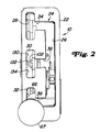
- Fig. 2
- eine Zusammenbauansicht der erfindungsgemäßen Steuerhebelanordnung von oben,
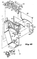
- Fig. 3A und 3B
- zwei zusammengehörige Explosionsdarstellungen einer erfindungsgemäßen Steuerhebelanordnung und
- Fig. 4A und 4B
- zwei zusammengehörige Explosionsdarstellungen einer erfindungsgemäßen Steuerhebelanordnung aus einer anderen Perspektive.
- Fig. 1
- a side assembly view of the control lever assembly according to the invention,
- Fig. 2
- an assembly view of the control lever assembly according to the invention from above,
- 3A and 3B
- two related exploded views of a control lever arrangement according to the invention and
- 4A and 4B
- two related exploded views of a control lever arrangement according to the invention from a different perspective.
Die Steuerhebelanordnung 10 des Ausführungsbeispiels enthält ein Gehäuse 12, welches eine plattenförmige Basiswandung 14 und eine umlaufende Randwandung 16 enthält. Die Basiswandung 14 weist in der Nähe ihres unteren Endes eine Bohrung 18 und eine radial zu der Bohrung 18 beabstandete bogenförmige Öffnung 20 auf. Radial unter der Öffnung 20 befindet sich ein bogenförmiger Zentrierfederschlitz 21. Die Steuerhebelanordnung 10 ist für die Verwendung bei elektronisch gesteuerten Lastschaltgetrieben, wie sie von verschiedenen Herstellern angeboten werden, vorgesehen.The
Eine Führungsplatte 22 ist an einem oberen Ende des Gehäuses 12 befestigt. In die Führungsplatte 22 ist ein Führungsschlitz 24 eingelassen. Der Führungsschlitz 24 enthält einen relativ langen, sich in Längsrichtung erstreckenden Hauptschlitzbereich 26. Der Führungsschlitz 24 enthält ferner einen sich in Längsrichtung erstreckenden Vorwärtsschlitz 28 für das Hoch- und Runterschalten bei Vorwärtsfahrt, einen sich in Längsrichtung erstreckenden Rückwärtsschlitz 30 für das Hoch- und Runterschalten bei Rückwärtsfahrt und einen sich in Längsrichtung erstreckenden Parkschlitz 32. Die Schlitze 28, 30 und 32 sind kürzer als der Hauptschlitz 26 und sind zu diesem in Querrichtung beabstandet. Die Schlitze 28 und 30 stehen mit dem Hauptschlitz 26 durch entsprechende querverlaufende Verbindungsschlitze 34 bzw. 36 in Verbindung. Der Parkschlitz 32 ist mit dem Hauptschlitz 26 durch einen sich quer erstreckenden Neutralschlitz 38 verbunden.A
Auf einer Seite des Gehäuses 12 ist eine Schalteraufnahme 31 ausgebildet. In diese Schalteraufnahme 31 ist ein im Handel erhältlicher Springschalter 33 einsetzbar. Der einrastbare Schalter 33 wird vorzugsweise als Neutralstartschalter verwendet, wie er in der US-A-5,251,733 beschrieben ist, auf die hiermit zwecks Offenbarung verwiesen wird.A
Ein Schwenkteil 40 enthält eine Welle 42, die drehbar von der Bohrung 18 aufgenommen wird, und einen Arm 44, der radial von einem Ende der Welle 42 absteht. Der Arm 44 wird durch zwei im wesentlichen parallele Seiten 46 und 48 gebildet, zwischen denen ein Schlitz 50 ausgebildet ist. Der Endbereich 52 des Arms 44 ist parallel zu der Achse der Welle 42 und in Richtung der Platte 14 ausgerichtet. In dem Endbereich 52 ist ein Schlitz 53 ausgebildet. Eine Schwenkbohrung 54 erstreckt sich durch die Seiten 46 und 48 in der Nähe der Welle 42. Eine Erhebung 56 ragt von einer Seite 46 vor und dient dem Eingriff mit dem Neutralstartschalter 33.A
Ein Hebel 60 ist durch einen Schwenkstift 62, der sich durch einen gabelförmigen Bereich 64 des Hebels 60 und durch die Schwenkbohrung 54 erstreckt, schwenkbar mit dem Arm 44 verbunden. Der Hebel 60 enthält einen Schaft 66, der innerhalb des Führungsschlitzes 24 bewegbar ist und der sich von dem gabelförmigen Bereich 64 bis zu einer Handhabe 67, die durch eine Bedienungsperson ergriffen werden kann, erstreckt. Der Schaft 66 trägt einen Magnetträger 68, der von einem mittleren Bereich des Schaftes 66 in Richtung der Gehäusewandung 14 vorsteht. Wie am besten aus Fig. 3B hervorgeht, ist ein Permanentmagnet 70 im Magnetträger 68 befestigt. Durch die beschriebene Ausbildung läßt sich der Hebel 60 in Längsrichtung um die Achse der Welle 42 und in Querrichtung um die Achse des Schwenkstiftes 62 verschwenken. Zwischen dem gabelförmigen Bereich 64 und dem Magnetträger 68 ist an dem Schaft 66 mittels eines Stiftes 74 eine Rastfeder 72 befestigt, die zwei Schenkel enthält, welche sich zwischen zwei von dem Stift 74 gehaltenen Schraubenfederabschnitten erstrecken.A
Zwischen dem Hebel 60 und der Wandung 14 ist ein Sektorteil 80 angeordnet. Das Sektorteil 80 weist einen im wesentlichen fächerförmigen Körper 81 auf, der teilweise durch eine vorstehende Randwandung 83 umgeben ist. Zwei bogenförmige Verstärkungsrippen 85 und 87 erstrecken sich über den Körper 81 von einer zur anderen Seite der Randwandung 83. Durch das untere Ende des Sektorteils 80 erstreckt sich eine Bohrung 78, die die Welle 42 drehbar aufnimmt. Das Sektorteil 80 weist eine erste zum Hebel 60 weisende Seite und eine zweite zur Wandung 14 weisende Seite auf. Das Sektorteil 80 hat eine erste, zweite und dritte Sensoröffnung 82, 84 und 86, die radial zu der Wellenbohrung 78 beabstandet und in einer bogenförmigen Reihe angeordnet sind, welche in der Achse der Bohrung 78 zentriert ist.A
Zu jeder Sensoröffnung 82, 84, 86 ist weiter radial innen eine entsprechende Rastöffnung 88, 90 bzw. 92 vorgesehen. Von der unteren Kante jeder Rastöffnung 88, 90, 92 steht beidseits ein Rastteil 94, 96 bzw. 98 vor. Jedes der Rastteile 94, 96 und 98 wird durch zwei Rampenflächen gebildet, welche von einem linear und quer zu der Achse der Welle 42 ausgerichteten Scheitel aus schräg nach unten geneigt sind. Die Rastfeder 72 kann lösbar mit den Rastteilen 94, 96 und 98 in Eingriff gebracht werden, um den Hebel 60 lösbar innerhalb eines der Schlitze 28, 30 oder 32 festzuhalten.For each
Ein bogenförmiger Zentrierfederschlitz 100 befindet sich in radialer Hinsicht weiter innen als die Rastöffnungen 88, 90, 92. Ein zweiter Permanentmagnet 102 wird in einer Ausnehmung 104 gehalten, welche radial über der mittleren Sensoröffnung 84 auf der Seite des Sektorteils 80 liegt, die der Wandung 14 zugewandt ist. Radial innerhalb der Verstärkungsrippe 87 befindet sich ein bogenförmiger Schlitz 106, der der Aufnahme des Endbereiches 52 des Schwenkteils 40 dient, in dem der Schlitz 53 ausgebildet ist.An arc-shaped centering
Eine Schaltkarte 110 ist auf der gegenüber dem Sektorteil 80 liegenden Seite der Wandung 14 radial weiter außen als die Öffnung 20 und im wesentlichen in Deckung mit den Sensoröffnungen 82 - 86 und mit dem Magnet 102 befestigt. Auf der Seite der Schaltkarte 110, die dem Sektorteil 80 zugewandt ist, sind Hallsensoren oder Schalter befestigt. Die Sensoren 120 und 122 sind in Deckung mit der Öffnung 82 befestigt und werden vorzugsweise als Vorwärts- bzw. als "Nicht-Neutral"-Schalter verwendet. Die Sensoren 124 und 126 sind in Deckung mit der Öffnung 84 befestigt und werden vorzugsweise als "Nicht-Neutral"- bzw. Rückwärtsschalter verwendet. Der Sensor 128 ist in Deckung mit der Öffnung 86 befestigt und wird vorzugsweise als Parkschalter verwendet. Die Sensoren 130, 132 und 134 sind in Deckung mit dem zweiten Magneten 102 befestigt und werden vorzugsweise als Schaltimpuls-, "Nichtschalt"- bzw. Schaltimpuls-Schalterverwendet. Die Schaltkarte 110 wird durch eine Abdeckung 140 geschützt, die mit der Wandung 14 verschraubbar ist.A
Eine Hebelrückstellfeder 142 enthält einen konzentrisch zur Welle 42 ausgerichteten Schraubenfederabschnitt, einen Schenkel 144, welcher mit der Randwandung 83 des Sektorteils 80 in Eingriff steht, und einen Schenkel 146, welcher von dem Schlitz 52 des Schwenkteils 40 aufgenommen wird. Die Feder 142 ist vorgespannt und drückt den Hebel 60 bezüglich des Sektorteils 80 gegen den Uhrzeigerdrehsinn (Fig. 1).A
Eine Querrückstellfeder 150 enthält einen zwischen den Seiten 46 und 48 des Schwenkteils 40 liegenden, konzentrisch zum Schwenkstift 62 ausgerichteten Schraubenfederabschnitt, einen Schenkel 152, welcher mit einem Teil des Schwenkteils 40 in Eingriff steht, und einen Schenkel 154 mit einem abgebogenen Ende 156, welches mit dem gabelförmigen Ende 64 des Hebels 60 in Eingriff steht. Die Feder 150 ist vorgespannt und drückt den Hebel 60 in Richtung des Sektorteils 80.A
Eine Zentrierfeder 160 enthält einen konzentrisch zur Welle 42 ausgerichteten Schraubenfederabschnitt und Schenkel 162 und 164, die sich durch den Schlitz 21 der Wandung 14 des Gehäuses 12 und den Schlitz 100 des Sektorteils 80 erstrecken. Die Zentrierfeder 160 ist vorgespannt, so daß die Schenkel 162 und 164 aufgespreizt oder voneinander weg bewegt werden. Damit wirkt die in die Schlitze 21 und 100 eingesetzte Feder 160 derart, daß das Sektorteil 80 hinsichtlich des Gehäuses 12 in eine mittlere Lage gedrängt wird. Die Federn 142 und 160 wirken damit zusammen, um den Hebel 60 in eine Lage zu drängen, in der der Magnetträger 68 in Deckung mit der Öffnung 86 des Sektorteils 80 liegt, so daß die Erhebung 56 normalerweise in Eingriff mit dem Neutralstartschalter 33 steht.A centering
Wie am besten aus Fig. 4B ersichtlich, ist eine Parkeingriffsfeder 170 beispielsweise durch nicht gezeigte Kopfschrauben an einem aufgesetzten Bereich 172, der auf der Unterseite der Führungsplatte 22 angeformt ist, befestigt.As can best be seen from FIG. 4B, a
Der nicht durch die Bedienungsperson betätigte Hebel 60 wird normalerweise durch die Federn 142 und 150 in eine Neutralstellung gedrückt, in der sich der Schaft 66 in dem Neutralschlitz 38 zwischen dem Hauptschlitz 26 und dem Parkschlitz 32 befindet. In dieser Position wird der Neutralstartschalter 33 durch die Erhebung 56 betätigt.
Der Hebel 60 kann nach links in die Position verschoben werden, die in Fig. 2 dargestellt ist. Hierbei wird der Schaft 66 in den Parkschlitz 32 und der Magnetträger 68 in die Öffnung 86 des Sektorteils 80 bewegt, der Magnet 70 betätigt den Halleffekt-Parkschalter 128, und die Rastfeder 72 wirkt mit dem Rastteil 98 zusammen, um den Hebel 60 lösbar in dieser Position zu halten.The
Aus dieser Position kann der Hebel 60 nach vorn (oder bezüglich Fig. 2 nach oben) verschoben werden, wobei das Sektorteil 80 sich mit dem Schaft 66 bewegt und der Magnet 102 den Halleffektschalter 130 betätigt. In dieser Lage wirkt die Feder 170 mit dem Schaft 66 zusammen und hält den Hebel 60 lösbar in dieser Position fest. Die Betätigung des Schalters 128, auf die eine Betätigung des Schalters 130 folgt, kann ausgenutzt werden, um eine nicht gezeigte mikroprozessor-unterstützte elektronische Steuereinheit zu veranlassen, ein nicht gezeigtes Lastschaltgetriebe in seinen Parkzustand zu überführen.From this position, the
Aus der zuerst beschriebenen Position kann der Hebel 60 nach rechts, dann nach vorn und schließlich nach links (oder bezüglich Fig. 2 nach rechts, nach oben und nach links) über den Querschlitz 36 in den Rückwärtsschlitz 30 bewegt werden. In diesem Fall bewegt sich der Magnetträger 68 in die Öffnung 84 des Sektorteils 80, der Magnet 70 betätigt den Halleffekt-Rückwärtsschalter 124 und den Halleffekt-"Nicht-Neutral"-Schalter 126, und die Rastfeder 72 wirkt mit dem Rastteil 96 zusammen, um den Hebel 60 lösbar in dem Rückwärtsschlitz 30 zu halten. Wird der Hebel 60 dann nach hinten bewegt, so bewegt sich das Sektorteil 80 mit dem Schaft 66 ebenfalls nach hinten, und der Magnet 102 betätigt den Halleffekt-"Runterschaltimpuls"-Schalter 134 und deaktiviert den Schalter 132. Wenn der Hebel 60 nach vorn bewegt wird, so bewegt sich das Sektorteil 80 mit dem Schaft 66 nach vorn, und der Magnet 102 betätigt den Halleffekt-"Hochschaltimpuls"-Schalter 130 und deaktiviert den Schalter 132. Wird der Hebel 60 losgelassen, so drückt die Feder 160 das Sektorteil 80 und den Hebel 60 bezüglich des Rückwärtsschlitzes 30 in eine mittlere Lage, in der nur der Schalter 132 betätigt wird. Die Betätigung der Schalter 130, 132 und 134 kann ausgenutzt werden, um eine nicht gezeigte mikroprozessor-unterstützte elektronische Steuereinheit zu veranlassen, ein nicht gezeigtes Lastschaltgetriebe im Bereich seiner Rückwärtsgangübersetzungen, die durch die Betätigung der Schalter 124 und 126 freigegeben sind, schrittweise hoch oder runter zu schalten.From the position described first, the
Aus der zuerst beschriebenen Position kann der Hebel 60 nach rechts, dann weiter nach vorn und schließlich nach links (oder bezüglich Fig. 2 nach rechts, weiter nach oben und nach links) über den Querschlitz 34 in den Vorwärtsschlitz 28 bewegt werden. In diesem Fall bewegt sich der Magnetträger 68 in die Öffnung 82 des Sektorteils 80, der Magnet 70 betätigt den Halleffekt-Vorwärtsschalter 120 und den Halleffekt-"Nicht-Neutral"-Schalter 122, und die Rastfeder 72 wirkt mit dem Rastteil 94 zusammen, um den Hebel 60 lösbar in dem Vorwärtsschlitz 28 zu halten. Wird der Hebel 60 dann nach hinten bewegt, so bewegt sich das Sektorteil 80 mit dem Schaft 66 nach hinten, und der Magnet 102 betätigt den Halleffekt-"Runterschaltimpuls"-Schalter 134 und deaktiviert den Schalter 132. Wenn der Hebel 60 nach vorn bewegt wird, bewegt sich das Sektorteil 80 mit dem Schaft 66 ebenfalls nach vorn, und der Magnet 102 betätigt den Halleffekt-"Hochschaltimpuls"-Schalter 130 und deaktiviert den Schalter 132. Wird der Hebel 60 losgelassen, so drückt die Feder 160 das Sektorteil 80 und den Hebel 60 bezüglich des Vorwärtsschlitzes 28 in eine mittlere Lage, in der nur der Schalter 132 betätigt wird. Die Betätigung der Schalter 130, 132 und 134 kann ausgenutzt werden, um eine nicht gezeigte mikroprozessor-unterstützte elektronische Steuereinheit zu veranlassen, ein nicht gezeigtes Lastschaltgetriebe im Bereich seiner Vorwärtsgangübersetzungen, die durch die Betätigung der Schalter 120 und 122 freigegeben sind, schrittweise hoch oder runter zu schalten.From the position described first, the
Vorzugsweise kann diese Schalthebelanordnung 10 in einer nicht gezeigten Fahrzeugkabine angeordnet und so ausgerichtet sein, daß die lange Dimension des Hauptschlitzes 26 sowie der Unterschlitze 28, 30 und 32 ungefähr parallel zu der Längsrichtung der Fahrzeugausrichtung verläuft.Preferably, this
Auch wenn die Erfindung lediglich anhand eines Ausführungsbeispiels beschrieben wurde, erschließen sich für den Fachmann im Lichte der vorstehenden Beschreibung sowie der Zeichnung viele verschiedenartige Alternativen, Modifikationen und Varianten, die unter die vorliegende Erfindung fallen.Even if the invention has only been described on the basis of an exemplary embodiment, many different alternatives, modifications and variants which fall under the present invention will become apparent to the person skilled in the art in the light of the above description and the drawing.
Beispielsweise können die Halleffekteinrichtungen durch im Handel erhältliche Springschalter oder durch verfügbare Reluktanzeinrichtungen ersetzt werden. Ferner können potentiometerartige, variable Umformer oder andere konventionelle, verstellbare Signalwandler verwendet werden, um an Stelle der Halleffekteinrichtungen die Lage des Hebels 60 festzustellen.For example, the Hall effect devices can be replaced by commercially available jump switches or by available reluctance devices. Furthermore, potentiometer-like, variable converters or other conventional, adjustable signal converters can be used to determine the position of the
Claims (11)
Applications Claiming Priority (3)
| Application Number | Priority Date | Filing Date | Title |
|---|---|---|---|
| US08/160,545 US5406860A (en) | 1993-12-01 | 1993-12-01 | Transmission shift lever assembly |
| US160545 | 1993-12-01 | ||
| EP94118262A EP0656492B1 (en) | 1993-12-01 | 1994-11-19 | Shift lever arrangement for transmission |
Related Parent Applications (2)
| Application Number | Title | Priority Date | Filing Date |
|---|---|---|---|
| EP94118262.8 Division | 1994-11-19 | ||
| EP94118262A Division EP0656492B1 (en) | 1993-12-01 | 1994-11-19 | Shift lever arrangement for transmission |
Publications (3)
| Publication Number | Publication Date |
|---|---|
| EP0754886A2 true EP0754886A2 (en) | 1997-01-22 |
| EP0754886A3 EP0754886A3 (en) | 1997-11-05 |
| EP0754886B1 EP0754886B1 (en) | 1999-06-02 |
Family
ID=22577326
Family Applications (3)
| Application Number | Title | Priority Date | Filing Date |
|---|---|---|---|
| EP94118262A Expired - Lifetime EP0656492B1 (en) | 1993-12-01 | 1994-11-19 | Shift lever arrangement for transmission |
| EP96117318A Expired - Lifetime EP0754886B1 (en) | 1993-12-01 | 1994-11-19 | Control lever assembly |
| EP96117317A Expired - Lifetime EP0754885B1 (en) | 1993-12-01 | 1994-11-19 | Control lever assembly |
Family Applications Before (1)
| Application Number | Title | Priority Date | Filing Date |
|---|---|---|---|
| EP94118262A Expired - Lifetime EP0656492B1 (en) | 1993-12-01 | 1994-11-19 | Shift lever arrangement for transmission |
Family Applications After (1)
| Application Number | Title | Priority Date | Filing Date |
|---|---|---|---|
| EP96117317A Expired - Lifetime EP0754885B1 (en) | 1993-12-01 | 1994-11-19 | Control lever assembly |
Country Status (8)
| Country | Link |
|---|---|
| US (1) | US5406860A (en) |
| EP (3) | EP0656492B1 (en) |
| JP (2) | JP3054324B2 (en) |
| BR (1) | BR9404703A (en) |
| CA (1) | CA2134792C (en) |
| DE (3) | DE59408700D1 (en) |
| ES (3) | ES2105475T3 (en) |
| FI (1) | FI945583A (en) |
Cited By (2)
| Publication number | Priority date | Publication date | Assignee | Title |
|---|---|---|---|---|
| DE19924791C1 (en) * | 1999-05-29 | 2001-02-08 | Deere & Co | Switching device for motor vehicle transmissions |
| IT201600069273A1 (en) * | 2016-07-04 | 2018-01-04 | Silatech S R L | Gearshift control device with modular structure. |
Families Citing this family (58)
| Publication number | Priority date | Publication date | Assignee | Title |
|---|---|---|---|---|
| GB9322836D0 (en) * | 1993-11-05 | 1993-12-22 | Rover Group | A selector mechanism for a vehicle transmission |
| US5722292A (en) * | 1994-06-02 | 1998-03-03 | Chrysler Corporation | Shift control mechanism to manually shift an automatic transmission |
| US5509322A (en) * | 1994-06-02 | 1996-04-23 | Chrysler Corporation | Shift control mechanism to manually shift an automatic transmission |
| US5680307A (en) * | 1995-06-28 | 1997-10-21 | Chrysler Corporation | Method of shifting in a manual mode of an electronically-controlled automatic transmission system |
| US5767769A (en) * | 1995-07-28 | 1998-06-16 | Chrysler Corporation | Method of displaying a shift lever position for an electronically-controlled automatic transmission |
| US5584209A (en) * | 1995-07-28 | 1996-12-17 | Chrysler Corporation | Electric circuit for manual shifting of an electronically-controlled automatic transmission system |
| US5675315A (en) * | 1995-07-28 | 1997-10-07 | Chrysler Corporation | Electronic gear display for an electronically-controlled automatic transmission system |
| DE19637533B4 (en) * | 1996-09-14 | 2007-03-22 | Zf Friedrichshafen Ag | Electric driving switch |
| SE510069C2 (en) | 1997-08-19 | 1999-04-12 | Scandmec Ab | Control device and the use of the control device in a motor vehicle |
| US6022291A (en) * | 1998-03-06 | 2000-02-08 | Equipment Technologies, Llc | Apparatus and method for controlling rotational speed and direction of a drive shaft of a crop sprayer |
| US6039132A (en) * | 1998-04-01 | 2000-03-21 | Deere & Company | Steering control system for tracked vehicle |
| US6027426A (en) * | 1998-05-28 | 2000-02-22 | Transmission Technologies Corporation | Neutral sensing and shift lever interlock assembly for a vehicular transmission |
| DE19832086B4 (en) * | 1998-07-16 | 2008-05-29 | Fico Triad S.A., Rubi | lever unit |
| US6022292A (en) * | 1999-02-12 | 2000-02-08 | Deere & Company | Method of adjusting an engine load signal used by a transmission controller |
| WO2001011271A1 (en) * | 1999-08-06 | 2001-02-15 | Stoneridge Control Devices, Inc. | Transmission range selector system |
| DE19938528A1 (en) * | 1999-08-13 | 2001-02-15 | Audi Ag | Control device for automatically and manually shiftable transmissions |
| US6170584B1 (en) | 1999-09-29 | 2001-01-09 | Deere & Company | Tracked vehicle steering system with steering pump monitoring |
| US6240351B1 (en) | 1999-09-29 | 2001-05-29 | Deere & Company | Tracked vehicle steering system with failure detection |
| US6244127B1 (en) | 1999-10-28 | 2001-06-12 | Teleflex, Incorporated | Mechanical or electrical transmission shifter |
| JP4572027B2 (en) * | 1999-11-05 | 2010-10-27 | 現代自動車株式会社 | Detent mechanism for shift lever unit |
| DE19959616A1 (en) * | 1999-12-10 | 2001-06-13 | Volkswagen Ag | Control device for an automatically and manually shiftable manual transmission in a motor vehicle |
| DE10022433B4 (en) * | 2000-05-09 | 2006-07-13 | Daimlerchrysler Ag | lever device |
| JP4481437B2 (en) * | 2000-05-31 | 2010-06-16 | 株式会社東海理化電機製作所 | Shift device |
| JP4481438B2 (en) | 2000-05-31 | 2010-06-16 | 株式会社東海理化電機製作所 | Shift device |
| US6382045B1 (en) | 2000-09-11 | 2002-05-07 | Teleflex Incorporated | Single lever shift assembly for an electronically controlled transmission |
| FR2826915B1 (en) * | 2001-07-06 | 2003-09-26 | Valeo | DEVICE FOR CONTROLLING A GEARBOX FOR A MOTOR VEHICLE |
| US6763294B2 (en) | 2002-05-06 | 2004-07-13 | Deere & Company | System and method for validating quadrature signals |
| KR100488693B1 (en) * | 2002-06-27 | 2005-05-11 | 현대자동차주식회사 | Lever apparatus of automatic transmission having an manual mode switch |
| US6766706B2 (en) * | 2002-11-01 | 2004-07-27 | Deere & Company | Control lever assembly |
| US6938509B2 (en) * | 2003-06-23 | 2005-09-06 | Cnh America Llc | Transmission shift control for selecting forward, reverse, neutral and park, and method of operation of the same |
| DE102004006150B3 (en) * | 2004-02-07 | 2005-09-15 | Teleflex Automotive Germany Gmbh | Control device for electronic step control for automatic transmission |
| DE102004060771B4 (en) * | 2004-12-17 | 2006-12-21 | Audi Ag | Device for switching translation changes |
| JP4723918B2 (en) * | 2005-06-03 | 2011-07-13 | トヨタ自動車株式会社 | Shift lever device for vehicle |
| JP2008260328A (en) * | 2007-04-10 | 2008-10-30 | Aisin Ai Co Ltd | Stopper structure of shift lever |
| US7701203B2 (en) * | 2007-05-11 | 2010-04-20 | Caterpillar Inc. | Method of sensing a position of a movable component of an operator interface in a machine |
| US7761254B2 (en) * | 2007-05-11 | 2010-07-20 | Caterpillar Inc | Operator interface assembly including a Hall effect element and machine using same |
| US7648002B2 (en) | 2007-06-08 | 2010-01-19 | Deere & Company | Vehicle with coordinated Ackerman and differential steering |
| US8087317B2 (en) * | 2007-11-06 | 2012-01-03 | Deere & Company | Interface system for control lever |
| SE0800488L (en) | 2008-02-29 | 2009-08-30 | Scania Cv Ab | Gear Set |
| US8196491B2 (en) | 2008-04-30 | 2012-06-12 | Allison Transmission, Inc. | Shift selector apparatus |
| US8204712B2 (en) * | 2008-10-07 | 2012-06-19 | Eaton Corporation | Ternary sensor inputs |
| US8044787B2 (en) * | 2008-10-07 | 2011-10-25 | Eaton Corporation | Discrete sensor inputs |
| DE102008042960B4 (en) * | 2008-10-20 | 2018-06-07 | Zf Friedrichshafen Ag | Arrangement for actuating at least one shift fork in a transmission |
| US10203033B2 (en) * | 2009-03-06 | 2019-02-12 | Eaton Cummins Automated Transmission Technologies Llc | Transmission control module with multiple sensor inputs |
| US8510004B2 (en) * | 2009-03-06 | 2013-08-13 | Eaton Corporation | Transmission control module with valve control |
| US8521376B2 (en) * | 2009-08-04 | 2013-08-27 | Eaton Corporation | Shift rail transmission position sensing |
| JP5643137B2 (en) * | 2011-03-15 | 2014-12-17 | 株式会社東海理化電機製作所 | Shift lever device |
| CN102678903B (en) * | 2012-05-10 | 2015-04-01 | 宁波高发汽车控制系统股份有限公司 | Automatic gearshift device of automobile |
| KR101397607B1 (en) * | 2012-11-06 | 2014-05-27 | 주식회사 에스엘 서봉 | Integrated double clutch transmission apparatus |
| CN103363088A (en) * | 2013-07-23 | 2013-10-23 | 安徽江淮汽车股份有限公司 | Dual-Hall-sensor DCT (Dual Clutch Transmission) shifting operation mechanism |
| US9989145B2 (en) | 2013-10-14 | 2018-06-05 | Club Car, Llc | Drive selector |
| US9752674B2 (en) * | 2014-12-13 | 2017-09-05 | Hyundai Motor Company | Automotive transmission |
| US10086924B2 (en) * | 2016-04-29 | 2018-10-02 | Hamilton Sundstrand Corporation | Alignment device for a selector lever |
| DE102016119842B3 (en) * | 2016-10-18 | 2018-02-22 | Preh Gmbh | Mode selector for a vehicle transmission with slide mechanism |
| KR101936894B1 (en) * | 2017-06-20 | 2019-01-11 | 경창산업주식회사 | Transmission control device sensing variation of gear levels and a car having the same |
| US10982759B2 (en) * | 2017-09-25 | 2021-04-20 | Honda Motor Co., Ltd. | Shift lever retention apparatus |
| CN111765244B (en) * | 2020-05-22 | 2022-02-15 | 北京理工大学 | Gear shifting device |
| USD949761S1 (en) * | 2021-10-11 | 2022-04-26 | David Heavrin | Automotive shift gate kit |
Citations (7)
| Publication number | Priority date | Publication date | Assignee | Title |
|---|---|---|---|---|
| US4425620A (en) | 1981-01-28 | 1984-01-10 | Steiger Tractor, Inc. | Electrical control for power shift transmission |
| US4442730A (en) | 1981-08-31 | 1984-04-17 | Twin Disc, Incorporated | Vehicle transmission system and a single lever control device therefor |
| US4855913A (en) | 1987-05-29 | 1989-08-08 | J. I. Case Company | Electronic control system for powershift transmission |
| US4926172A (en) | 1988-09-02 | 1990-05-15 | Dickey-John Corporation | Joystick controller |
| US4991454A (en) | 1989-12-01 | 1991-02-12 | Ford New Holland, Inc. | Power shift transmission shift pattern |
| US5243871A (en) | 1992-08-13 | 1993-09-14 | Ford New Holland, Inc. | Control lever apparatus for generating electrical control signals |
| US5251733A (en) | 1992-07-31 | 1993-10-12 | Deere & Company | Transmission control with limp-home function |
Family Cites Families (13)
| Publication number | Priority date | Publication date | Assignee | Title |
|---|---|---|---|---|
| US3757598A (en) * | 1971-06-21 | 1973-09-11 | Massey Ferguson Inc | Single lever control for transmission |
| HU174407B (en) * | 1975-01-23 | 1979-12-28 | Zahnradfabrik Friedrichshafen | Starting switch for electrohydraulic drives |
| US4228879A (en) * | 1978-09-28 | 1980-10-21 | Deere & Company | Tractor transmission shift control |
| GB2054773A (en) * | 1979-07-23 | 1981-02-18 | Massey Ferguson Services Nv | Transmission Ratio Selecting Mechanisms |
| DE3138827A1 (en) * | 1981-09-30 | 1983-04-14 | Wabco Westinghouse Fahrzeugbremsen GmbH, 3000 Hannover | GEAR SELECTOR FOR A GEARBOX |
| IT1155179B (en) * | 1982-05-03 | 1987-01-21 | Fiat Allis Europ | DEVICE TO COMMAND THE RUNNING OF A VEHICLE |
| JPS60175857A (en) * | 1984-02-20 | 1985-09-10 | Diesel Kiki Co Ltd | Automatic speed-change controller for car |
| US4830156A (en) * | 1988-02-26 | 1989-05-16 | J. I. Case Company | Mechanical transmission clutch control |
| DE3807881A1 (en) * | 1988-03-10 | 1989-09-21 | Porsche Ag | SWITCHING DEVICE FOR AN AUTOMATIC TRANSMISSION OF A MOTOR VEHICLE |
| JPH03153958A (en) * | 1989-11-09 | 1991-07-01 | Aisin Aw Co Ltd | Manual select device of automatic transmission for vehicle |
| US5082097A (en) * | 1989-12-05 | 1992-01-21 | Dickey-John Corporation | Transmission controller |
| JPH04101061U (en) * | 1991-02-05 | 1992-09-01 | 日産デイーゼル工業株式会社 | Shift device for multi-speed transmission |
| US5184523A (en) * | 1992-03-18 | 1993-02-09 | Adams Rite Manufacturing Company | Transmission control employing bi-directionally guided handle, with locking |
-
1993
- 1993-12-01 US US08/160,545 patent/US5406860A/en not_active Expired - Lifetime
-
1994
- 1994-10-26 JP JP6287537A patent/JP3054324B2/en not_active Expired - Fee Related
- 1994-11-01 CA CA002134792A patent/CA2134792C/en not_active Expired - Fee Related
- 1994-11-19 EP EP94118262A patent/EP0656492B1/en not_active Expired - Lifetime
- 1994-11-19 ES ES94118262T patent/ES2105475T3/en not_active Expired - Lifetime
- 1994-11-19 ES ES96117317T patent/ES2135833T3/en not_active Expired - Lifetime
- 1994-11-19 DE DE59408700T patent/DE59408700D1/en not_active Expired - Fee Related
- 1994-11-19 DE DE59408373T patent/DE59408373D1/en not_active Expired - Fee Related
- 1994-11-19 ES ES96117318T patent/ES2132827T3/en not_active Expired - Lifetime
- 1994-11-19 EP EP96117318A patent/EP0754886B1/en not_active Expired - Lifetime
- 1994-11-19 DE DE59403553T patent/DE59403553D1/en not_active Expired - Fee Related
- 1994-11-19 EP EP96117317A patent/EP0754885B1/en not_active Expired - Lifetime
- 1994-11-23 BR BR9404703A patent/BR9404703A/en not_active IP Right Cessation
- 1994-11-28 FI FI945583A patent/FI945583A/en unknown
-
2000
- 2000-02-02 JP JP2000025746A patent/JP2000170887A/en active Pending
Patent Citations (7)
| Publication number | Priority date | Publication date | Assignee | Title |
|---|---|---|---|---|
| US4425620A (en) | 1981-01-28 | 1984-01-10 | Steiger Tractor, Inc. | Electrical control for power shift transmission |
| US4442730A (en) | 1981-08-31 | 1984-04-17 | Twin Disc, Incorporated | Vehicle transmission system and a single lever control device therefor |
| US4855913A (en) | 1987-05-29 | 1989-08-08 | J. I. Case Company | Electronic control system for powershift transmission |
| US4926172A (en) | 1988-09-02 | 1990-05-15 | Dickey-John Corporation | Joystick controller |
| US4991454A (en) | 1989-12-01 | 1991-02-12 | Ford New Holland, Inc. | Power shift transmission shift pattern |
| US5251733A (en) | 1992-07-31 | 1993-10-12 | Deere & Company | Transmission control with limp-home function |
| US5243871A (en) | 1992-08-13 | 1993-09-14 | Ford New Holland, Inc. | Control lever apparatus for generating electrical control signals |
Cited By (2)
| Publication number | Priority date | Publication date | Assignee | Title |
|---|---|---|---|---|
| DE19924791C1 (en) * | 1999-05-29 | 2001-02-08 | Deere & Co | Switching device for motor vehicle transmissions |
| IT201600069273A1 (en) * | 2016-07-04 | 2018-01-04 | Silatech S R L | Gearshift control device with modular structure. |
Also Published As
| Publication number | Publication date |
|---|---|
| EP0754885B1 (en) | 1999-09-01 |
| EP0656492B1 (en) | 1997-07-30 |
| JP2000170887A (en) | 2000-06-23 |
| FI945583A0 (en) | 1994-11-28 |
| ES2135833T3 (en) | 1999-11-01 |
| EP0754886A3 (en) | 1997-11-05 |
| CA2134792A1 (en) | 1995-06-02 |
| CA2134792C (en) | 1998-11-24 |
| DE59403553D1 (en) | 1997-09-04 |
| EP0754886B1 (en) | 1999-06-02 |
| ES2132827T3 (en) | 1999-08-16 |
| EP0754885A2 (en) | 1997-01-22 |
| JPH07190179A (en) | 1995-07-28 |
| DE59408373D1 (en) | 1999-07-08 |
| EP0754885A3 (en) | 1997-11-05 |
| FI945583A (en) | 1995-06-02 |
| US5406860A (en) | 1995-04-18 |
| ES2105475T3 (en) | 1997-10-16 |
| BR9404703A (en) | 1995-07-25 |
| JP3054324B2 (en) | 2000-06-19 |
| EP0656492A2 (en) | 1995-06-07 |
| EP0656492A3 (en) | 1995-08-02 |
| DE59408700D1 (en) | 1999-10-07 |
Similar Documents
| Publication | Publication Date | Title |
|---|---|---|
| EP0656492B1 (en) | Shift lever arrangement for transmission | |
| DE19924791C1 (en) | Switching device for motor vehicle transmissions | |
| DE112018001244T5 (en) | Monostable rotary switch | |
| DE60214958T2 (en) | switching device | |
| DE3100504A1 (en) | LOCKING DEVICE FOR A CARDANOUS VEHICLE TRANSMISSION SWITCHING DEVICE ACTUATING A CABLE | |
| EP0175061A1 (en) | Transmitter for the gearbox of an automotive vehicle | |
| DE112018001264T5 (en) | 360º ROTATING HANDLE CONTROL DEVICE WITH SWITCHING DEVICE RESET FUNCTIONALITY INSTEAD OF A ROTATING HANDLE IN A FIXED POSITION | |
| DE102010037954A1 (en) | Transmission shifting device for a vehicle | |
| DE3116833A1 (en) | GUIDE AND LOCKING DEVICE FOR THE SHIFTING MECHANISM OF A GEARBOX | |
| EP1938050A1 (en) | Display device for a motor vehicle provided with a swivelling indicator having first and/or second optical wave guide areas | |
| DE102015102607A1 (en) | Switching device for an automatic transmission of a motor vehicle | |
| DE10022433B4 (en) | lever device | |
| EP0622718B1 (en) | Control lever | |
| DE4127537C2 (en) | Shift lever control device | |
| WO1992009832A1 (en) | Mechanical shifting device | |
| DE3905769A1 (en) | Electric driving switch | |
| DE3340394C2 (en) | Device for displaying the current position of a gear selector lever | |
| EP1243816A2 (en) | Range selection apparatus for an automatic transmission | |
| DE4420582A1 (en) | Retractable switching device with a display device for the position of the switching device | |
| DE10015079C2 (en) | Switching device for an automatic transmission of a motor vehicle | |
| EP0230661A1 (en) | Gear box | |
| DE19526951C2 (en) | Switching device for an automatic transmission | |
| DE60010556T2 (en) | Device for the gradual shift control of a transmission | |
| DE202009003485U1 (en) | joystick | |
| DE1480670C (en) | Series switching device for a change gear of motor vehicles |
Legal Events
| Date | Code | Title | Description |
|---|---|---|---|
| PUAI | Public reference made under article 153(3) epc to a published international application that has entered the european phase |
Free format text: ORIGINAL CODE: 0009012 |
|
| AC | Divisional application: reference to earlier application |
Ref document number: 656492 Country of ref document: EP |
|
| AK | Designated contracting states |
Kind code of ref document: A2 Designated state(s): DE ES FR GB IT |
|
| PUAL | Search report despatched |
Free format text: ORIGINAL CODE: 0009013 |
|
| AK | Designated contracting states |
Kind code of ref document: A3 Designated state(s): DE ES FR GB IT |
|
| 17P | Request for examination filed |
Effective date: 19971031 |
|
| 17Q | First examination report despatched |
Effective date: 19971211 |
|
| GRAG | Despatch of communication of intention to grant |
Free format text: ORIGINAL CODE: EPIDOS AGRA |
|
| GRAG | Despatch of communication of intention to grant |
Free format text: ORIGINAL CODE: EPIDOS AGRA |
|
| GRAH | Despatch of communication of intention to grant a patent |
Free format text: ORIGINAL CODE: EPIDOS IGRA |
|
| RAP1 | Party data changed (applicant data changed or rights of an application transferred) |
Owner name: DEERE & COMPANY |
|
| GRAH | Despatch of communication of intention to grant a patent |
Free format text: ORIGINAL CODE: EPIDOS IGRA |
|
| GRAA | (expected) grant |
Free format text: ORIGINAL CODE: 0009210 |
|
| AC | Divisional application: reference to earlier application |
Ref document number: 656492 Country of ref document: EP |
|
| AK | Designated contracting states |
Kind code of ref document: B1 Designated state(s): DE ES FR GB IT |
|
| GBT | Gb: translation of ep patent filed (gb section 77(6)(a)/1977) |
Effective date: 19990603 |
|
| REF | Corresponds to: |
Ref document number: 59408373 Country of ref document: DE Date of ref document: 19990708 |
|
| ET | Fr: translation filed | ||
| REG | Reference to a national code |
Ref country code: ES Ref legal event code: FG2A Ref document number: 2132827 Country of ref document: ES Kind code of ref document: T3 |
|
| PLBE | No opposition filed within time limit |
Free format text: ORIGINAL CODE: 0009261 |
|
| STAA | Information on the status of an ep patent application or granted ep patent |
Free format text: STATUS: NO OPPOSITION FILED WITHIN TIME LIMIT |
|
| 26N | No opposition filed | ||
| PGFP | Annual fee paid to national office [announced via postgrant information from national office to epo] |
Ref country code: FR Payment date: 20001117 Year of fee payment: 7 |
|
| PGFP | Annual fee paid to national office [announced via postgrant information from national office to epo] |
Ref country code: ES Payment date: 20001128 Year of fee payment: 7 |
|
| PG25 | Lapsed in a contracting state [announced via postgrant information from national office to epo] |
Ref country code: ES Free format text: LAPSE BECAUSE OF NON-PAYMENT OF DUE FEES Effective date: 20011120 |
|
| REG | Reference to a national code |
Ref country code: GB Ref legal event code: IF02 |
|
| PG25 | Lapsed in a contracting state [announced via postgrant information from national office to epo] |
Ref country code: FR Free format text: LAPSE BECAUSE OF NON-PAYMENT OF DUE FEES Effective date: 20020730 |
|
| REG | Reference to a national code |
Ref country code: FR Ref legal event code: ST |
|
| REG | Reference to a national code |
Ref country code: FR Ref legal event code: ST |
|
| REG | Reference to a national code |
Ref country code: ES Ref legal event code: FD2A Effective date: 20021213 |
|
| PG25 | Lapsed in a contracting state [announced via postgrant information from national office to epo] |
Ref country code: IT Free format text: LAPSE BECAUSE OF NON-PAYMENT OF DUE FEES Effective date: 20051119 |
|
| PGFP | Annual fee paid to national office [announced via postgrant information from national office to epo] |
Ref country code: DE Payment date: 20061019 Year of fee payment: 13 |
|
| PGFP | Annual fee paid to national office [announced via postgrant information from national office to epo] |
Ref country code: GB Payment date: 20061122 Year of fee payment: 13 |
|
| GBPC | Gb: european patent ceased through non-payment of renewal fee |
Effective date: 20071119 |
|
| PG25 | Lapsed in a contracting state [announced via postgrant information from national office to epo] |
Ref country code: DE Free format text: LAPSE BECAUSE OF NON-PAYMENT OF DUE FEES Effective date: 20080603 |
|
| PG25 | Lapsed in a contracting state [announced via postgrant information from national office to epo] |
Ref country code: GB Free format text: LAPSE BECAUSE OF NON-PAYMENT OF DUE FEES Effective date: 20071119 |