EP0751384A2 - Indicators for external pressure applied to a flexible liquid chamber - Google Patents
Indicators for external pressure applied to a flexible liquid chamber Download PDFInfo
- Publication number
- EP0751384A2 EP0751384A2 EP96304725A EP96304725A EP0751384A2 EP 0751384 A2 EP0751384 A2 EP 0751384A2 EP 96304725 A EP96304725 A EP 96304725A EP 96304725 A EP96304725 A EP 96304725A EP 0751384 A2 EP0751384 A2 EP 0751384A2
- Authority
- EP
- European Patent Office
- Prior art keywords
- liquid
- chamber
- indicator
- pressure
- liquid outlet
- Prior art date
- Legal status (The legal status is an assumption and is not a legal conclusion. Google has not performed a legal analysis and makes no representation as to the accuracy of the status listed.)
- Withdrawn
Links
Images

Classifications
-
- A—HUMAN NECESSITIES
- A61—MEDICAL OR VETERINARY SCIENCE; HYGIENE
- A61F—FILTERS IMPLANTABLE INTO BLOOD VESSELS; PROSTHESES; DEVICES PROVIDING PATENCY TO, OR PREVENTING COLLAPSING OF, TUBULAR STRUCTURES OF THE BODY, e.g. STENTS; ORTHOPAEDIC, NURSING OR CONTRACEPTIVE DEVICES; FOMENTATION; TREATMENT OR PROTECTION OF EYES OR EARS; BANDAGES, DRESSINGS OR ABSORBENT PADS; FIRST-AID KITS
- A61F5/00—Orthopaedic methods or devices for non-surgical treatment of bones or joints; Nursing devices; Anti-rape devices
- A61F5/01—Orthopaedic devices, e.g. splints, casts or braces
- A61F5/30—Pressure-pads
- A61F5/34—Pressure pads filled with air or liquid
-
- A—HUMAN NECESSITIES
- A61—MEDICAL OR VETERINARY SCIENCE; HYGIENE
- A61B—DIAGNOSIS; SURGERY; IDENTIFICATION
- A61B5/00—Measuring for diagnostic purposes; Identification of persons
- A61B5/103—Detecting, measuring or recording devices for testing the shape, pattern, colour, size or movement of the body or parts thereof, for diagnostic purposes
- A61B5/1036—Measuring load distribution, e.g. podologic studies
-
- G—PHYSICS
- G01—MEASURING; TESTING
- G01L—MEASURING FORCE, STRESS, TORQUE, WORK, MECHANICAL POWER, MECHANICAL EFFICIENCY, OR FLUID PRESSURE
- G01L7/00—Measuring the steady or quasi-steady pressure of a fluid or a fluent solid material by mechanical or fluid pressure-sensitive elements
- G01L7/02—Measuring the steady or quasi-steady pressure of a fluid or a fluent solid material by mechanical or fluid pressure-sensitive elements in the form of elastically-deformable gauges
-
- G—PHYSICS
- G01—MEASURING; TESTING
- G01L—MEASURING FORCE, STRESS, TORQUE, WORK, MECHANICAL POWER, MECHANICAL EFFICIENCY, OR FLUID PRESSURE
- G01L7/00—Measuring the steady or quasi-steady pressure of a fluid or a fluent solid material by mechanical or fluid pressure-sensitive elements
- G01L7/18—Measuring the steady or quasi-steady pressure of a fluid or a fluent solid material by mechanical or fluid pressure-sensitive elements using liquid as the pressure-sensitive medium, e.g. liquid-column gauges
-
- A—HUMAN NECESSITIES
- A61—MEDICAL OR VETERINARY SCIENCE; HYGIENE
- A61B—DIAGNOSIS; SURGERY; IDENTIFICATION
- A61B2562/00—Details of sensors; Constructional details of sensor housings or probes; Accessories for sensors
- A61B2562/16—Details of sensor housings or probes; Details of structural supports for sensors
- A61B2562/168—Fluid filled sensor housings
-
- A—HUMAN NECESSITIES
- A61—MEDICAL OR VETERINARY SCIENCE; HYGIENE
- A61F—FILTERS IMPLANTABLE INTO BLOOD VESSELS; PROSTHESES; DEVICES PROVIDING PATENCY TO, OR PREVENTING COLLAPSING OF, TUBULAR STRUCTURES OF THE BODY, e.g. STENTS; ORTHOPAEDIC, NURSING OR CONTRACEPTIVE DEVICES; FOMENTATION; TREATMENT OR PROTECTION OF EYES OR EARS; BANDAGES, DRESSINGS OR ABSORBENT PADS; FIRST-AID KITS
- A61F5/00—Orthopaedic methods or devices for non-surgical treatment of bones or joints; Nursing devices; Anti-rape devices
- A61F5/01—Orthopaedic devices, e.g. splints, casts or braces
- A61F5/0102—Orthopaedic devices, e.g. splints, casts or braces specially adapted for correcting deformities of the limbs or for supporting them; Ortheses, e.g. with articulations
- A61F2005/0188—Orthopaedic devices, e.g. splints, casts or braces specially adapted for correcting deformities of the limbs or for supporting them; Ortheses, e.g. with articulations having pressure sensors
Definitions
- This invention relates to applied pressure indicators and has particular application to interface pressure sensing in the field of medicine.
- Interface pressure measuring in medical terms is a practice for measuring pressures on a patient's skin. For example, when the patient is sitting or lying down on a mattress or cushion, pressure being measured of the interface between the supporting surface and the body's skeletal frame.
- the interface is known as the orthotic interface.
- An electromechanical micro-processor controlled unit is often used to measure patient orthotic interface. However, such a unit is expensive.
- the present invention provides an inexpensive device which can be used, not only to measure patient orthotic interface, but has other applications. For example, to measure the pressure applied to the limb of a patient when bandaging the limb.
- an applied pressure indicator comprises a hollow, flexible, chamber containing liquid, a liquid outlet duct extending from the chamber interior, and means for restricting outward passage of liquid within the duct, whereby, when the chamber is subjected to an external pressure, the volume of liquid displaced from the chamber is indicative of the intensity of said pressure.
- At least the liquid outlet duct of the indicator is preferably of transparent material.
- the means for restricting outward passage of liquid within the duct may comprise more than one restriction.
- the liquid outlet duct may bear markings indicative of external pressure applied to the chamber.
- the term 'liquid' includes other flowable media, such as pastes.
- the liquid in the chamber may comprise a gel. Where more than one indicator is employed the liquids in the respective chambers of the indicators may differ in density and/or colour.
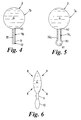
- an applied pressure indicator 1 comprises a hollow, flexible, chamber 2 containing a liquid 3 within its interior 4, a liquid outlet duct 5 extending from the chamber interior 4, and means comprising restrictors 6, 7 for restricting outward passage of liquid 3 within the duct 5.
- the volume of liquid 3 displaced from the chamber 2 into the duct 5 is indicative of the intensity of said pressure.
- the indicator 1 is a one-piece component of flexible plastics material, in this example a transparent polyethylene.
- the liquid is a glycerol gel.
- the duct 5 is blind-ended and is formed by two sections, 9, 10, each of bulbous form.
- the sections 9, 10 are bulbous to accommodate the displacement of liquid 3.
- Each bulbous section bears graduation markings, indicated by reference 15 in the case of section 9, and by 16 in the case of section 10.
- the markings 15, 16 are indicative of the external pressure 8 applied to the flexible chamber 2.
- the indicator 1 is positioned where it is desired to measure patient orthotic interface pressure.
- the intensity of the applied pressure can then be determined by correlation, that is to say by comparing the extent of liquid displacement with markings 15 or 16.
- the indicator 1 can be viewed as a form of transducer.
- a more approximate indication of intensity of applied external pressure is provided by visual examination of the duct sections 9, 10. If section 9 is full of liquid then the applied pressure is acceptable. If liquid appears in section 10, the applied pressure is too great.
- the indicator 1 may also be used to measure pressure applied to the limb of a patient when bandaging the limb.
- a plurality of indicators 1 may be employed, disposed in one or more rows. Such an arrangement has particular advantage in the application of a plaster cast to a patient's leg where it is desirable to monitor a range of pressures.
- the indicators 1 of Figure 2 are mounted on a backing 20 comprising a sheet of flexible material.
- the lines 21 indicate layers of bandage.
- Indicators could be incorporated in bandaging or casting components.
- the liquids employed by the indicators 1 of Figure 2 may differ in colour and/or density, in order to suit requirements.
- an indicator la may have an outlet duct 5a employing only one restrictor, namely restrictor 25.
- More than two restrictors may be used, if desirable.
- Restrictor sizes and/or lengths of outlet duct may vary, according to requirements.
- Figure 4 illustrates an indicator 1b with a single restrictor 30 and a substantially parallel (uniform bore) outlet duct 5b of capillary form.
- the outlet 5b may be provided with a small-bore air vent 33 at the end remote from chamber 2.
- a flexible strip or panel 31 attached to outlet 5b bears graduation markings 32.
- the panel 31 may be integral with the outlet 5a.
- Figure 5 illustrates an indicator 1c provided with a single restrictor 40 and an outlet 5c having a bulbous reservoir 41 at the end remote from chamber 2, for accommodating air pushed out of the outlet 5a by displacement of liquid from chamber 2.
- a graduated panel 31c is mounted on the indicator 1c or is integral therewith,
- Indicators 1, 1a, 1b, 1c may be disposable after use, or may be rendered reusable by displacing, by squeeze action, liquid back into the chambers 2.
Abstract
With reference to Figure 1, an applied pressure indicator 1 (shown in plan view) comprises a hollow, flexible, closed chamber 2 containing a liquid 3 within its interior 4, a liquid outlet duct 5 extending from the chamber interior 4, and means comprising restrictors 6, 7 for restricting outward passage of liquid 3 within the duct 5. When the flexible chamber 2 is subjected to external pressure, as indicated by arrows 8, the volume of liquid 3 displaced from the chamber 2 into the duct 5 is indicative of the intensity of said pressure. The indicator 1 illustrated is a one-piece component of flexible plastics material, in this example a transparent polyethylene. The liquid is a glycerol gel.
Description
- This invention relates to applied pressure indicators and has particular application to interface pressure sensing in the field of medicine.
- Interface pressure measuring in medical terms is a practice for measuring pressures on a patient's skin. For example, when the patient is sitting or lying down on a mattress or cushion, pressure being measured of the interface between the supporting surface and the body's skeletal frame. The interface is known as the orthotic interface.
- An electromechanical micro-processor controlled unit is often used to measure patient orthotic interface. However, such a unit is expensive.
- The present invention provides an inexpensive device which can be used, not only to measure patient orthotic interface, but has other applications. For example, to measure the pressure applied to the limb of a patient when bandaging the limb.
- According to the invention, an applied pressure indicator comprises a hollow, flexible, chamber containing liquid, a liquid outlet duct extending from the chamber interior, and means for restricting outward passage of liquid within the duct, whereby, when the chamber is subjected to an external pressure, the volume of liquid displaced from the chamber is indicative of the intensity of said pressure.
- At least the liquid outlet duct of the indicator is preferably of transparent material.
- The means for restricting outward passage of liquid within the duct may comprise more than one restriction.
- The liquid outlet duct may bear markings indicative of external pressure applied to the chamber.
- As used herein, the term 'liquid' includes other flowable media, such as pastes.
- The liquid in the chamber may comprise a gel. Where more than one indicator is employed the liquids in the respective chambers of the indicators may differ in density and/or colour.
- An embodiment of the invention will now be described by way of example only, with reference to the accompanying drawings, wherein :-
- Figure 1 is a plan view, in section, of an applied pressure indicator,
- Figure 2 illustrates an arrangement wherein a plurality of indicators are employed,
- Figures 3, 4 and 5 illustrate modifications, and
- Figure 6 is a side view of the indicator illustrated by Figure 1.
- In the figures, like reference numerals refer to like features and components.
- With reference to Figure 1, an
applied pressure indicator 1 comprises a hollow, flexible,chamber 2 containing aliquid 3 within itsinterior 4, aliquid outlet duct 5 extending from thechamber interior 4, andmeans comprising restrictors liquid 3 within theduct 5. - When the
flexible chamber 2 is subjected to external pressure, as indicated byarrow 8, the volume ofliquid 3 displaced from thechamber 2 into theduct 5 is indicative of the intensity of said pressure. - The
indicator 1 is a one-piece component of flexible plastics material, in this example a transparent polyethylene. The liquid is a glycerol gel. - The
duct 5 is blind-ended and is formed by two sections, 9, 10, each of bulbous form. Thesections liquid 3. Each bulbous section bears graduation markings, indicated byreference 15 in the case ofsection 9, and by 16 in the case ofsection 10. Themarkings external pressure 8 applied to theflexible chamber 2. - In use, the
indicator 1 is positioned where it is desired to measure patient orthotic interface pressure. - The pressure, (arrows 8), applied by the weight of the patient deforms the
flexible chamber 2 wherebyliquid 3 is displaced into theduct 5, past therestriction 6, and, if substantial enough, past therestrictor 7 as well. The intensity of the applied pressure can then be determined by correlation, that is to say by comparing the extent of liquid displacement withmarkings indicator 1 can be viewed as a form of transducer. - A more approximate indication of intensity of applied external pressure is provided by visual examination of the
duct sections section 9 is full of liquid then the applied pressure is acceptable. If liquid appears insection 10, the applied pressure is too great. - The
indicator 1 may also be used to measure pressure applied to the limb of a patient when bandaging the limb. - With reference to Figure 2, a plurality of
indicators 1 may be employed, disposed in one or more rows. Such an arrangement has particular advantage in the application of a plaster cast to a patient's leg where it is desirable to monitor a range of pressures. - The
indicators 1 of Figure 2 are mounted on abacking 20 comprising a sheet of flexible material. - The
lines 21 indicate layers of bandage. - Indicators could be incorporated in bandaging or casting components.
- The liquids employed by the
indicators 1 of Figure 2 may differ in colour and/or density, in order to suit requirements. - With reference to Figure 3, an indicator la may have an
outlet duct 5a employing only one restrictor, namelyrestrictor 25. - More than two restrictors may be used, if desirable.
- Restrictor sizes and/or lengths of outlet duct may vary, according to requirements.
- An outlet duct need not be of bulbous form; indeed Figures 4 and 5 illustrate such arrangements.
- Figure 4 illustrates an
indicator 1b with asingle restrictor 30 and a substantially parallel (uniform bore)outlet duct 5b of capillary form. Theoutlet 5b may be provided with a small-bore air vent 33 at the end remote fromchamber 2. A flexible strip orpanel 31 attached tooutlet 5b bearsgraduation markings 32. Thepanel 31 may be integral with theoutlet 5a. - Figure 5 illustrates an indicator 1c provided with a
single restrictor 40 and anoutlet 5c having abulbous reservoir 41 at the end remote fromchamber 2, for accommodating air pushed out of theoutlet 5a by displacement of liquid fromchamber 2. A graduatedpanel 31c is mounted on the indicator 1c or is integral therewith, - Where possible and desirable, any of the features or arrangements disclosed herein may be substituted for, or added to, other of said features or arrangements.
-
Indicators chambers 2.
Claims (16)
- An applied pressure indicator characterised in that it comprises a hollow, flexible, chamber (1, 1a, 1b, 1c) containing liquid (3), a liquid outlet duct (5, 5a, 5b, 5c) extending from the chamber interior (4), and means (6, 7, 25, 40) for restricting outward passage of liquid within the duct, whereby, when the chamber (1, 1a, 1b, 1c) is subjected to an external pressure (8), the volume of liquid (3) displaced from the chamber is indicative of the intensity of said pressure.
- An applied pressure indicator as claimed in claim 1, wherein at least the liquid outlet duct (5, 5a, 5b, 5, 5d) of the indicator is of transparent material.
- An applied pressure indicator as claimed in claim 1 or 2, wherein the means (6, 7) for restricting outward passage of liquid within the duct comprise more than one restriction.
- An applied pressure indicator as claimed in claim 1, 2, or 3, wherein the liquid outlet duct bears markings (15, 16, 32, 32c) indicative of external pressure applied to the chamber.
- An applied pressure indicator as claimed in any one of claims 1 to 4 wherein the liquid (3) in the chamber (1, 1a, 1b, 1c) comprises a gel.
- An applied pressure indicator as claimed in claim 5, wherein the gel comprises a glycerol gel.
- An applied pressure indicator as claimed in any one of claims I to 6, wherein the liquid outlet duct (5, 5a, 9, 10) is of bulbous form.
- An applied pressure indicator as claimed in any one of claims 1 to 6, wherein the liquid outlet duct is formed by two sections (9, 10), each section being of bulbous form.
- An applied pressure indicator as claimed in any one of claims 1 to 6, wherein the liquid outlet duct (5b, 5c) is of substantially uniform bore.
- An applied pressure indicator as claimed in any one of claims 4 to 9, wherein said markings are borne on a panel (31, 31c) attached to the liquid outlet duct.
- An assembly comprising a plurality of applied pressure indicators, each according to any one of claims 1 to 10, mounted on a backing (20).
- An assembly as claimed in claim 11, wherein the backing (20) comprises a sheet of flexible material.
- An assembly as claimed in claim 11 or 12, wherein the liquids employed by the applied pressure indicators differ in colour and/or density.
- A method of measuring patient orthotic interface pressure, comprising use of an applied pressure indicator as claimed in any one of claims 1 to 10, whereby the weight of the patient displaces liquid (3) from the chamber (1, 1a, 1b, 1c) of the indicator, into the liquid outlet duct thereof, and subsequently conducting a visual examination of the outlet duct in order to obtain an indication of said interface pressure.
- A method of measuring pressure applied to a limb of a patient when bandaging the limb, comprising incorporating an assembly as claimed in claim 12 in said bandaging, and subsequently conducting a visual examination of the liquid outlet ducts of the indicators of the assembly in order to obtain an indication of pressure applied to the patient's limb by said bandaging.
- A method of measuring pressure applied to the limb of a patient by a plaster cast, comprising incorporating an assembly as claimed in claim 12 in said cast, and subsequently conducting a visual examination of the liquid outlet ducts of the indicators of the assembly, in order to obtain an indication of pressure applied to the patient's limb by said plaster cast.
Applications Claiming Priority (2)
| Application Number | Priority Date | Filing Date | Title |
|---|---|---|---|
| GB9513323 | 1995-06-30 | ||
| GBGB9513323.7A GB9513323D0 (en) | 1995-06-30 | 1995-06-30 | Improvements in or relating to applied pressure indicators |
Publications (2)
| Publication Number | Publication Date |
|---|---|
| EP0751384A2 true EP0751384A2 (en) | 1997-01-02 |
| EP0751384A3 EP0751384A3 (en) | 1997-10-15 |
Family
ID=10776902
Family Applications (1)
| Application Number | Title | Priority Date | Filing Date |
|---|---|---|---|
| EP96304725A Withdrawn EP0751384A3 (en) | 1995-06-30 | 1996-06-26 | Indicators for external pressure applied to a flexible liquid chamber |
Country Status (2)
| Country | Link |
|---|---|
| EP (1) | EP0751384A3 (en) |
| GB (2) | GB9513323D0 (en) |
Cited By (2)
| Publication number | Priority date | Publication date | Assignee | Title |
|---|---|---|---|---|
| NL1014566C2 (en) * | 2000-03-06 | 2001-10-04 | Beleggings En Exploitatie Mij | Implantable pressure monitoring device. |
| WO2005102151A2 (en) * | 2004-04-27 | 2005-11-03 | ETH Zürich | Passive sensor with wireless transmission |
Citations (7)
| Publication number | Priority date | Publication date | Assignee | Title |
|---|---|---|---|---|
| GB514144A (en) * | 1938-12-12 | 1939-10-31 | Margaret Sudheim | Apparatus for the measurement of pressures in fluids |
| US4106342A (en) * | 1977-04-14 | 1978-08-15 | Onni Sore Sormunen | Pressure measuring apparatus |
| GB1572814A (en) * | 1977-04-07 | 1980-08-06 | Robertshaw Skil Ltd | Pressure sensing |
| JPS5868635A (en) * | 1981-10-21 | 1983-04-23 | Hitachi Ltd | Absolute pressure transmitting device |
| US5311834A (en) * | 1991-05-21 | 1994-05-17 | Ross Gregory E | Indicating device |
| US5398851A (en) * | 1993-08-06 | 1995-03-21 | River Medical, Inc. | Liquid delivery device |
| US5427279A (en) * | 1992-07-02 | 1995-06-27 | Kaufman Products Inc. | Dispenser with reservoir actuation |
Family Cites Families (5)
| Publication number | Priority date | Publication date | Assignee | Title |
|---|---|---|---|---|
| GB1224161A (en) * | 1968-03-15 | 1971-03-03 | Abbirko Instr Ltd | Improvements in or relating to fluid pressure indicating devices |
| US3877137A (en) * | 1974-05-30 | 1975-04-15 | Hakim Co Ltd | Method of making implantable pressure sensor |
| GB1533660A (en) * | 1974-12-30 | 1978-11-29 | Kay F | Pressure gauges |
| GB1520408A (en) * | 1975-06-23 | 1978-08-09 | Ackroyd D J | Cardiographic method |
| FR2365327A1 (en) * | 1976-09-28 | 1978-04-21 | Remih Harry | DEVICE FOR TRAINING CONTROL AND MEASUREMENT OF TENSION OF VAGINAL MUSCLES |
-
1995
- 1995-06-30 GB GBGB9513323.7A patent/GB9513323D0/en active Pending
-
1996
- 1996-06-26 GB GB9613395A patent/GB2302947A/en not_active Withdrawn
- 1996-06-26 EP EP96304725A patent/EP0751384A3/en not_active Withdrawn
Patent Citations (7)
| Publication number | Priority date | Publication date | Assignee | Title |
|---|---|---|---|---|
| GB514144A (en) * | 1938-12-12 | 1939-10-31 | Margaret Sudheim | Apparatus for the measurement of pressures in fluids |
| GB1572814A (en) * | 1977-04-07 | 1980-08-06 | Robertshaw Skil Ltd | Pressure sensing |
| US4106342A (en) * | 1977-04-14 | 1978-08-15 | Onni Sore Sormunen | Pressure measuring apparatus |
| JPS5868635A (en) * | 1981-10-21 | 1983-04-23 | Hitachi Ltd | Absolute pressure transmitting device |
| US5311834A (en) * | 1991-05-21 | 1994-05-17 | Ross Gregory E | Indicating device |
| US5427279A (en) * | 1992-07-02 | 1995-06-27 | Kaufman Products Inc. | Dispenser with reservoir actuation |
| US5398851A (en) * | 1993-08-06 | 1995-03-21 | River Medical, Inc. | Liquid delivery device |
Non-Patent Citations (1)
| Title |
|---|
| PATENT ABSTRACTS OF JAPAN vol. 007, no. 160 (P-210), 14 July 1983 & JP 58 068635 A (HITACHI SEISAKUSHO KK), 23 April 1983, * |
Cited By (3)
| Publication number | Priority date | Publication date | Assignee | Title |
|---|---|---|---|---|
| NL1014566C2 (en) * | 2000-03-06 | 2001-10-04 | Beleggings En Exploitatie Mij | Implantable pressure monitoring device. |
| WO2005102151A2 (en) * | 2004-04-27 | 2005-11-03 | ETH Zürich | Passive sensor with wireless transmission |
| WO2005102151A3 (en) * | 2004-04-27 | 2005-12-29 | Eth Zuerich | Passive sensor with wireless transmission |
Also Published As
| Publication number | Publication date |
|---|---|
| GB9513323D0 (en) | 1995-09-06 |
| GB2302947A (en) | 1997-02-05 |
| GB9613395D0 (en) | 1996-08-28 |
| EP0751384A3 (en) | 1997-10-15 |
Similar Documents
| Publication | Publication Date | Title |
|---|---|---|
| US4993428A (en) | Method of and means for implanting a pressure and force sensing apparatus | |
| EP0329599B1 (en) | Apparatus for perfusing body cavities | |
| US5083573A (en) | Method of and means for implanting a pressure and force sensing apparatus | |
| US4421124A (en) | Pressure detection arrangement | |
| US4066082A (en) | Force applicator including indicator | |
| US6120457A (en) | In vivo zeroing of catheter pressure sensor | |
| AU729467B2 (en) | Pressure transducer apparatus with disposable dome | |
| EP0904728A3 (en) | Implantable pressure indicator | |
| WO1990014042A1 (en) | Dolorimeter apparatus | |
| FR2751743B1 (en) | SELF INTEGRATED METHOD AND DEVICE IN A MEASUREMENT BRIDGE | |
| US3720201A (en) | Disposable body fluid pressure monitor | |
| AU2820384A (en) | Body cavity drainage device | |
| US8764685B2 (en) | Biomedical interface pressure transducer for medical tourniquets | |
| US4036216A (en) | Body fluid pressure system | |
| EP0751384A2 (en) | Indicators for external pressure applied to a flexible liquid chamber | |
| US4286603A (en) | Pressure detection arrangement | |
| US5195536A (en) | Self-adhering noninvasive intracorporeal movement detector | |
| ATE181805T1 (en) | PORTABLE MEDICAL MEASUREMENT AND DIAGNOSTIC DEVICE | |
| WO1996003080A1 (en) | Osteoporosis apparatus | |
| US3890842A (en) | Disposable manometer | |
| US7325458B2 (en) | Peak contact pressure sensor system (PCPSS) and smart brain retractor system (SBRS) | |
| US5564435A (en) | Noninvasive compartment measurement device | |
| US4854157A (en) | Device for measuring effective porosity | |
| US20140350433A1 (en) | Pressure measuring device and fixing device with pressure measuring function for affected part | |
| Lindahl et al. | Impression technique for the assessment of oedema: technical improvement and methodological evaluation of a new technique |
Legal Events
| Date | Code | Title | Description |
|---|---|---|---|
| PUAI | Public reference made under article 153(3) epc to a published international application that has entered the european phase |
Free format text: ORIGINAL CODE: 0009012 |
|
| AK | Designated contracting states |
Kind code of ref document: A2 Designated state(s): AT BE CH DE DK ES FR GB IE IT LI NL PT SE |
|
| PUAL | Search report despatched |
Free format text: ORIGINAL CODE: 0009013 |
|
| AK | Designated contracting states |
Kind code of ref document: A3 Designated state(s): AT BE CH DE DK ES FR GB IE IT LI NL PT SE |
|
| STAA | Information on the status of an ep patent application or granted ep patent |
Free format text: STATUS: THE APPLICATION IS DEEMED TO BE WITHDRAWN |
|
| 18D | Application deemed to be withdrawn |
Effective date: 19980416 |