EP0749704A2 - Sandal - Google Patents
Sandal Download PDFInfo
- Publication number
- EP0749704A2 EP0749704A2 EP96304607A EP96304607A EP0749704A2 EP 0749704 A2 EP0749704 A2 EP 0749704A2 EP 96304607 A EP96304607 A EP 96304607A EP 96304607 A EP96304607 A EP 96304607A EP 0749704 A2 EP0749704 A2 EP 0749704A2
- Authority
- EP
- European Patent Office
- Prior art keywords
- sole
- sandal
- strap
- cleat
- attachment holes
- Prior art date
- Legal status (The legal status is an assumption and is not a legal conclusion. Google has not performed a legal analysis and makes no representation as to the accuracy of the status listed.)
- Granted
Links
Images


Classifications
-
- A—HUMAN NECESSITIES
- A43—FOOTWEAR
- A43B—CHARACTERISTIC FEATURES OF FOOTWEAR; PARTS OF FOOTWEAR
- A43B5/00—Footwear for sporting purposes
- A43B5/14—Shoes for cyclists
Definitions
- cycling footwear Many advancements have been made bicycle technology, including cycling footwear. For example, many refinements have been made to cycling footwear to lower pedaling energy losses. This is accomplished in part by using a rigid sole so that energy is not lost through flexure of the sole. Energy loss also is minimized by securing the footwear snugly to the foot. See, for example, Japanese Laid-Open Patent Application 3-254702. Although it is very desirable to avoid energy loss, it is also desirable to have footwear that is comfortable to use over long periods of time so that the cyclist does not feel discomfort during a long trip. Such comfort must also be available when the cyclist is using the cycling shoe for ordinary walking. However, some cycling shoes cause the feet to sweat in summer when the shoes are worn for a long time. This can be somewhat uncomfortable.
- a sandal comprises a sole and a strap connected to the sole for securing the sandal to the foot, wherein the sole includes a cleat attachment hole for fixing a cleat on a bottom surface thereof.
- the sole includes a relatively rigid middle sole and a covering sole disposed on a lower surface of the middle sole.
- the middle sole provides rigidity to minimize energy loss during cycling.
- the covering sole includes a window for exposing a portion of the middle sole, and at least two cleat attachment holes are disposed in the window for fixing a cleat to a bottom surface of the sole.
- the cleat does not extend below the lowermost surface of the sole.
- the sandal may be used effectively for cycling without interfering with normal walking.
- the heel-securing band 2a is provided with a heel-coupling means 6 for coupling the releasable side of the left heel-securing band 2aL and the releasable side of the right heel-securing band 2aR.
- the heel-coupling means 6 may be a ring provided with a slit and affixed to the releasable end of the right heel-securing band 2aR by sewing or other means.
- the toe-securing band 2b is provided with a toe-coupling means 7 for coupling the releasable side of the left toe-securing band 2bL and the releasable side of the right toe-securing band 2bR.
- the left heel-securing band 2aL rises from the left side of the sole 1 for the left sandal, passes through the heel-coupling means 6, and folds back.
- a hook-and-loop fastener (such as a Velcro® fastener) is affixed to the facing surfaces of the folding portion on the releasable side of the left heel-securing band 2aL.
- the left toe-securing band 2bL rises from the left side of the sole 1 for the left sandal, passes through the toe-coupling means 7, and folds back.
- a hook-and-loop fastener (such as a Velcro® fastener) is affixed to the facing surfaces of the folding portion on the releasable side of the left toe-securing band 2bL.
- the middle sole 4 is slightly curved downward in a convex fashion (with the exception of an area on the heel side).
- the entire middle sole 4 is curved, having a point of inflection P.
- the curving forms a curved surface that follows the lower surface of the foot.
- Cleat attachment holes 11 for fitting in a cleat are formed at positions near the lower end point of this convex surface.
- a window 12 is formed in the lower-side portion of the covering soles 5, and the lower surface of the middle sole 4 is exposed.
- the cleat attachment holes 11 are formed in the exposed portion 4a of the middle sole 4.
- the cleat 3 (whose upper-end surface is bonded under pressure to the lower-end surface) is movably and rotatably secured to the exposed portion 4a.
- the cleat 3 is affixed to the middle sole 4 with a plurality of hexagonal-head bolts 13 and with nuts (the latter are not shown) in a well known manner.
- the cleat 3 can be attached while allowed to move in the longitudinal direction with respect to the sole 1, and the angle with respect to the longitudinal direction can be varied somewhat. As noted above, in this embodiment the cleat 3 does not extend below the lowermost surface of the sole 1.
- the distance between the front end of the sole and the central point in the longitudinal direction of the row of holes is set at 25 to 45 percent of the distance between the front and back ends of the sole, and the distance between the holes in the row is set at no more than 25 percent of the width of the sole in the vicinity of this row of holes.
- the surface area of the cleat attachment holes 11 is small, and the strength of the sole does not suffer.
- the pitch remains small when the cleat 3 is secured to the sole at an angle, thus making it possible to make the angle between the cleat 3 and the cleat attachment holes 11 relatively large even when only a small gap is formed between the cleat attachment bolts 13 and the cleat attachment holes 11. Adjusting the securing position by means of such a large attachment angle is convenient for the cyclist.
- the middle sole 4 is concave overall. Specifically, the left and right sides are raised as shown in Figures 6 through 10.
- the cleat attachment holes 11 for cleat coupling are provided at the position of maximum width.
- the middle sole is thicker in a linear region 21 extending in the longitudinal direction on the underside of the central region than on the left or right sides thereof. In the longitudinal region near the point of inflection P, the middle sole 4 is thinner on the inside (on the downside in Figure 11) than on the outside.
Abstract

Description
- The present invention is directed to cycling footwear and, more specifically, to a sandal that can be used for walking and to which a cleat may be mounted for cycling with cleat-fixing pedals.
- Many advancements have been made bicycle technology, including cycling footwear. For example, many refinements have been made to cycling footwear to lower pedaling energy losses. This is accomplished in part by using a rigid sole so that energy is not lost through flexure of the sole. Energy loss also is minimized by securing the footwear snugly to the foot. See, for example, Japanese Laid-Open Patent Application 3-254702. Although it is very desirable to avoid energy loss, it is also desirable to have footwear that is comfortable to use over long periods of time so that the cyclist does not feel discomfort during a long trip. Such comfort must also be available when the cyclist is using the cycling shoe for ordinary walking. However, some cycling shoes cause the feet to sweat in summer when the shoes are worn for a long time. This can be somewhat uncomfortable.
- The present invention is directed to cycling footwear, and more specifically to a sandal that can be worn comfortably in hot weather and can be used for both cycling and regular walking. In one embodiment of the present invention, a sandal comprises a sole and a strap connected to the sole for securing the sandal to the foot, wherein the sole includes a cleat attachment hole for fixing a cleat on a bottom surface thereof. In a more specific embodiment, the sole includes a relatively rigid middle sole and a covering sole disposed on a lower surface of the middle sole. The middle sole provides rigidity to minimize energy loss during cycling. The covering sole includes a window for exposing a portion of the middle sole, and at least two cleat attachment holes are disposed in the window for fixing a cleat to a bottom surface of the sole. Preferably, the cleat does not extend below the lowermost surface of the sole. Thus, the sandal may be used effectively for cycling without interfering with normal walking.
-
- Figure 1 is a right side view of a particular embodiment of a sandal according to the present invention;
- Figure 2 is a top view of the sandal shown in Figure 1;
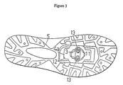
- Figure 3 is a bottom view of the sandal shown in Figure 1;
- Figure 4 is a top view of a particular embodiment of a middle sole used in the sandal shown in Figure 1;
- Figure 5 is a cross sectional view of the middle sole taken along line V-V in Figure 4;
- Figure 6 is a cross sectional view of the middle sole taken along line VI-VI in Figure 11;
- Figure 7 is a cross sectional view of the middle sole taken along line VII-VII in Figure 11;
- Figure 8 is a cross sectional view of the middle sole taken along line VIII-VIII in Figure 11;
- Figure 9 is a cross sectional view of the middle sole taken along line IX-IX in Figure 11;
- Figure 10 is a cross sectional view of the middle sole taken along line X-X in Figure 11; and
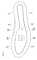
- Figure 11 is a bottom view of the middle sole used in the sandal shown in Figure 1.
- Figure 1 is a right side view of a particular embodiment of a sandal according to the present invention. Figure 2 is a top view of the sandal, and Figure 3 is a bottom view of the sandal. A left sandal is shown in the figures, but the right sandal is merely a mirror image of the left sandal so a separate description of the right sandal will be omitted.
- As shown in Figures 1-3, a sandal 0 comprises a sole 1 and a foot-securing band or strap 2 affixed to the sole 1 for securing sole 1 to the cyclist's foot. The bottom of the sole 1 has cleat attachment holes 11 for fitting in a cleat 3 (Figure 3). The cleat attachment holes 11 are located in front of the sole center and are shaped as recessions in the sole surface. In this embodiment, the lower surface of cleat 3 does not extend below the ground-contacting surface of the sole 1. As a result, the wearer experiences no discomfort in the area of the foot sole during walking.
- The sole 1 comprises a middle sole 4 and covering
soles 5. Middle sole 4 is formed of a hard resin, metal, or some other material of comparatively poor elasticity. Coveringsoles 5 are joined to the upper and lower surfaces of the middle sole 4. Coveringsoles 5 provide an elastic cover for the middle sole 4 and are formed of hard rubber or a soft material with comparatively good flexibility. - The foot-supporting band 2 comprises a heel-securing
band 2a, a toe-securingband 2b, and a connecting band 2c. Heel-securingband 2a is a back strap for securing the heel area of the foot, toe-securingband 2b is a front strap for securing the toe area of the foot, and connecting band 2c connects the heel-securingband 2a and the toe-securingband 2b in the longitudinal direction of the foot. The heel-securingband 2a comprises a left heel-securing band 2aL and a right heel-securing band 2aR. The left end of the left heel-securing band 2aL is affixed to the sole 1, while the other end can be released. Similarly, the right end of the right heel-securing band 2aR is affixed to the sole 1, while the other end can be released. The toe-securingband 2b comprises a left toe-securing band 2bL and a right toe-securing band 2bR. The left end of the left toe-securing band 2bL is affixed to the sole 1, while the other end can be released. Similarly, the right end of the right toe-securing band 2bR is affixed to the sole 1, while the other end can be released. In the left sandal, the connecting band 2c connects the left heel-securing band 2aL and the left toe-securing band 2bL in the longitudinal direction. - The heel-securing
band 2a is provided with a heel-coupling means 6 for coupling the releasable side of the left heel-securing band 2aL and the releasable side of the right heel-securing band 2aR. In this embodiment, the heel-coupling means 6 may be a ring provided with a slit and affixed to the releasable end of the right heel-securing band 2aR by sewing or other means. Similarly, the toe-securingband 2b is provided with a toe-coupling means 7 for coupling the releasable side of the left toe-securing band 2bL and the releasable side of the right toe-securing band 2bR. In this embodiment, the toe-coupling means 7 may be a ring provided with a slit and affixed to the releasable end of the right toe-securing band 2bR by a stitch or other means 8. For example, the releasable end of the right toe-securing band 2bR can be folded back, and a looped stitched portion 9 can be formed by sewing. The ring 7 is passed through this stitched portion 9. - The left heel-securing band 2aL rises from the left side of the sole 1 for the left sandal, passes through the heel-coupling means 6, and folds back. A hook-and-loop fastener (such as a Velcro® fastener) is affixed to the facing surfaces of the folding portion on the releasable side of the left heel-securing band 2aL. Similarly, the left toe-securing band 2bL rises from the left side of the sole 1 for the left sandal, passes through the toe-coupling means 7, and folds back. A hook-and-loop fastener (such as a Velcro® fastener) is affixed to the facing surfaces of the folding portion on the releasable side of the left toe-securing band 2bL.
- As shown in Figures 1 and 5, the middle sole 4 is slightly curved downward in a convex fashion (with the exception of an area on the heel side). In this embodiment, the entire middle sole 4 is curved, having a point of inflection P. The curving forms a curved surface that follows the lower surface of the foot. Cleat attachment holes 11 for fitting in a cleat are formed at positions near the lower end point of this convex surface. As shown in Figure 3, a
window 12 is formed in the lower-side portion of the coveringsoles 5, and the lower surface of the middle sole 4 is exposed. The cleat attachment holes 11 are formed in the exposed portion 4a of the middle sole 4. The cleat 3 (whose upper-end surface is bonded under pressure to the lower-end surface) is movably and rotatably secured to the exposed portion 4a. The cleat 3 is affixed to the middle sole 4 with a plurality of hexagonal-head bolts 13 and with nuts (the latter are not shown) in a well known manner. The cleat 3 can be attached while allowed to move in the longitudinal direction with respect to the sole 1, and the angle with respect to the longitudinal direction can be varied somewhat. As noted above, in this embodiment the cleat 3 does not extend below the lowermost surface of the sole 1. - As shown in Figure 4, the cleat attachment holes 11 are shaped as slits extending in the longitudinal direction of the footwear. The cleat attachment holes 11 may comprise two slits arranged in a row. Of course, the two cleat attachment holes 11 are not limited to slits and can be round holes, circular holes, or elliptical holes arranged in the form of islands in the longitudinal direction. The parts of the two
cleat attachment bolts 13 that pass through the cleat attachment holes 11 are narrower (in the transverse direction that is orthogonal to the longitudinal direction) than the corresponding cleat attachment holes 11. The pitch of the row of two holes, that is, the distance between the centers of the two holes in the row in the transverse direction, is set at 14 mm. or less. In this embodiment, the distance between the front end of the sole and the central point in the longitudinal direction of the row of holes is set at 25 to 45 percent of the distance between the front and back ends of the sole, and the distance between the holes in the row is set at no more than 25 percent of the width of the sole in the vicinity of this row of holes. As a result, the surface area of the cleat attachment holes 11 is small, and the strength of the sole does not suffer. In addition, the pitch remains small when the cleat 3 is secured to the sole at an angle, thus making it possible to make the angle between the cleat 3 and the cleat attachment holes 11 relatively large even when only a small gap is formed between thecleat attachment bolts 13 and the cleat attachment holes 11. Adjusting the securing position by means of such a large attachment angle is convenient for the cyclist. - Figures 4-11 elaborate on the structure of the middle sole 4. Figure 5 is a cross section taken along line V-V in Figure 4. Figures 6-10 are cross sections taken along lines VI-VI, VII-VII, VIII-VIII, IX-IX, and X-X, respectively, in Figure 11. As shown in Figure 5, the middle sole 4 has maximum thickness in an area near the point of inflection P (or near a horizontal line containing the point of inflection P). As shown in Figures 6 and 7, the middle sole 4 has maximum width in the front portion (in the portion closer to the toes and farther from the point of inflection P). As shown in Figures 9 and 10, the middle sole 4 has minimum width in the back portion (in the portion closer to the heel and farther from the point of inflection P).
- The middle sole 4 is concave overall. Specifically, the left and right sides are raised as shown in Figures 6 through 10. The cleat attachment holes 11 for cleat coupling are provided at the position of maximum width. The middle sole is thicker in a
linear region 21 extending in the longitudinal direction on the underside of the central region than on the left or right sides thereof. In the longitudinal region near the point of inflection P, the middle sole 4 is thinner on the inside (on the downside in Figure 11) than on the outside. - To use the sandal, the cyclist inserts his or her foot into the sandal, and the free end of the releasable portion of the left toe-securing band 2bL is passed through the toe-coupling means 7 and folded back. The left toe-securing band 2bL and the right toe-securing band 2bR can be joined and tightened by aligning the hook and loop fasteners on the facing sides of the folded left toe-securing band 2bL. The degree of tension can be adjusted by varying the folding position. The free end of the releasable portion of the left heel-securing band 2aL is then passed through the heel-coupling means 6 and folded back. The left heel-securing band 2aL and right heel-securing band 2aR can be joined and tightened by aligning the fasteners on the facing sides of the folded left heel-securing band 2aL. The degree of tension can be adjusted by varying the folding position. Adjusting the degree of tension in such a manner allows the heel-securing
band 2a and the toe-securingband 2b to snugly secure the toe area and the heel area of the foot against the sole 1. - After the sandals are secured to the cyclist's foot, the cyclist inserts the cleats 3 into the bicycle pedals at predetermined positions. The pedaling force acts to further bend the sole 1 around the point of inflection, but the magnitude of this force varies periodically from high to low, and the fact that the middle sole 4 is hard and hence rigid allows the sole to rapidly regain its original shape as soon as the pedaling force decreases. Such a bending force also acts to bend the middle sole 4 and to stretch the connecting band 2c, but the deformation of the middle sole 4 is suppressed by the tension of the connecting band 2c, which is made of a material that is hard to stretch. As noted above when discussing the structures shown in Figures 6 through 10, the central portion is thicker than the left or right side, and thus generally functions as a stiff structural member while preserving its elasticity. Resistance to bending is also high because of the considerable thickness of the central bending portion.
- Thus, the cleated sandal of this invention has only minor energy losses because it is rigid and easily restores its original state. The cleat, which does not extend below the lower-end surface of the sole 1, does not impede walking when the rider gets off the bicycle and walks. Thus, the sandal can be used for both cycling and walking. Because the sandals have good ventilation, they can be used as sporting footwear, and particularly sporting footwear for summer use. The degree of tension is easy to adjust, and the range of cleat adjustment angles is large.
- While the above is a description of various embodiments of the present invention, further modifications may be employed without departing from the spirit and scope of the present invention. Thus, the scope of the invention should not be limited by the specific structures disclosed. Instead, the true scope of the invention should be determined by the following claims. Of course, although labeling symbols are used in the claims in order to facilitate reference to the figures, the present invention is not intended to be limited to the constructions in the appended figures by such labeling.
Claims (17)
- A sandal comprising:a sole (1);a strap (2) connected to the sole (1); and characterised in that the sole (1) includes a cleat attachment hole (11) for fixing a cleat (3) on a bottom surface thereof.
- The sandal according to Claim 1 wherein the sole (1) includes a plurality of attachment holes (11) for fixing the cleat (3) on a bottom surface thereof.
- The sandal according to Claim 2 wherein a plurality of cleat attachment holes (11) are disposed in front of a centre portion of the sole (1).
- The sandal according to either one of Claims 2 or 3 wherein the sole comprises a middle sole (4) and a covering sole (5) disposed on a lower surface of the middle sole (4), wherein the covering sole (5) includes a window (12) for exposing a portion of the middle sole (4) and wherein the plurality of cleat attachment holes (11) are disposed in the window (12).
- The sandal according to any one of Claims 2 to 4 wherein a plurality.of cleat attachment holes (11) are arranged in a row.
- The sandal according to any one of claims 2 to 5 wherein two of the plurality of cleat attachment holes (11) are spaced apart by 14mm or less.
- The sandal according to any one of Claims 2 to 6 wherein the plurality of cleat attachment holes (11) includes two cleat attachment holes (11), wherein a distance between a front end of the sole (1) and a longitudinal centre point of the two holes (11) is set at approximately 25% to 45% of a distance between the front end of the sole (1) and a rear end of the sole (1), and wherein a distance between the two cleat attachment holes (11) is not greater than 25% of a width of the sole (1) at the location of the two cleat attachment holes (11).
- A sandal as claimed in Claim 2 or any claim dependent thereon wherein the sole (1) includes:
two cleat attachment holes (11) for fixing a cleat (3) to a bottom surface of the sole (1). - The sandal according to Claim 2 or any claim dependent thereon wherein the two cleat attachment holes (11), or two of the plurality of cleat attachment holes, are arranged in a row in a lateral direction of the sole.
- The sandal according to Claim 2 or any claim dependent thereon wherein the two cleat attachment holes (11), or two of the plurality of cleat attachment holes, are elongated in a longitudinal direction of the sole (1).
- The sandal according to any preceding claim wherein the strap (2) includes;a rear strap (2a) disposed at a rear portion of the sandal;a front strap (2b) disposed at a front portion of the sandal; anda connecting band (2c) connected to the rear strap (2a) and to the front strap (2b).
- The sandal according to Claim 11 wherein the front strap (2b) includes:a left front strap (2bL) coupled to a left side of the sandal;a right front strap (2bR) coupled to a right side of the sandal; andwherein the left front strap (2bL) and the right front strap (2bR) are structured to be selectively connected to and disconnected from each other.
- The sandal according to either of Claims 11 or 12 wherein the rear strap (2a) includes:a left rear strap (2aL) coupled to a left side of the sandal;a right rear strap (2aR) coupled to a right side of the sandal; andwherein the left rear strap (2aL) and the right rear strap (2aR) are structured to be selectively connected to and disconnected from each other.
- A sandal as claimed in any one of Claims 11 to 13 wherein:the rear strap (2a) defines an open space between the rear strap (2a) and the sole (1);the front strap (2b) defines an open space between the front strap (2b) and the sole (1); andthe connecting band (2c) defines an open space between the connecting band (2c) and the sole (1).
- The sandal according to any one of Claims 11 to 14 wherein the front strap (2b) includes:a left front strap (2bL) coupled to a left side of the sandal and defining an open space between the left front strap (2bL) and the sole (1);a right front strap (2bR) coupled to a right side of the sandal and defining an open space between the right front strap (2bR) and the sole (1); andwherein the left front strap (2bL) and the right front strap (2bR) are structured to be selectively connected to and disconnected from each other.
- The sandal according to any of Claims 11 to 15 wherein the rear strap (2a) includes:a left rear strap (2aL) coupled to a left side of the sandal and defining an open space between the left rear strap (2aL) and the sole (1);a right rear strap (2aR) coupled to a right side of the sandal and defining an open space between the right rear strap (2aR) and the sole (1); andwherein the left rear strap (2aL) and the right rear strap (2aR) are structured to be selectively connected to and disconnected from each other.
- A sandal as claimed in Claim 4 or any claim dependent thereon, wherein a cleat is provided, attached via a cleat attachment hole, such that the cleat does not extend further from the inner sole than does the surrounding portion of the covering sole.
Applications Claiming Priority (3)
| Application Number | Priority Date | Filing Date | Title |
|---|---|---|---|
| JP181060/95 | 1995-06-23 | ||
| JP18106095 | 1995-06-23 | ||
| JP18106095A JP3590141B2 (en) | 1995-06-23 | 1995-06-23 | Sandals |
Publications (3)
| Publication Number | Publication Date |
|---|---|
| EP0749704A2 true EP0749704A2 (en) | 1996-12-27 |
| EP0749704A3 EP0749704A3 (en) | 1997-03-05 |
| EP0749704B1 EP0749704B1 (en) | 2000-08-30 |
Family
ID=16094089
Family Applications (1)
| Application Number | Title | Priority Date | Filing Date |
|---|---|---|---|
| EP96304607A Expired - Lifetime EP0749704B1 (en) | 1995-06-23 | 1996-06-21 | Sandal |
Country Status (5)
| Country | Link |
|---|---|
| US (1) | US5687492A (en) |
| EP (1) | EP0749704B1 (en) |
| JP (1) | JP3590141B2 (en) |
| CN (1) | CN1089569C (en) |
| DE (1) | DE69610030T2 (en) |
Cited By (3)
| Publication number | Priority date | Publication date | Assignee | Title |
|---|---|---|---|---|
| EP0795280A2 (en) * | 1996-03-15 | 1997-09-17 | Shimano Inc. | Cycling shoe core, molding method and molding apparatus for same |
| FR2775424A1 (en) * | 1998-03-02 | 1999-09-03 | Salomon Sa | CYCLING SHOE EQUIPPED WITH AN AUTOMATIC LOCKING SHOE ON A PEDAL |
| EP2984957A1 (en) * | 2014-08-13 | 2016-02-17 | Mavic S.A.S. | Sports shoe |
Families Citing this family (30)
| Publication number | Priority date | Publication date | Assignee | Title |
|---|---|---|---|---|
| US6052920A (en) * | 1998-04-10 | 2000-04-25 | Bite, Llc | Sandal with x-cross weave straps |
| USD417947S (en) * | 1998-05-28 | 1999-12-28 | Wolverine World Wide, Inc. | Sandal upper |
| USD422402S (en) * | 1998-05-28 | 2000-04-11 | Wolverine World Wide, Inc. | Sandal upper |
| USD421330S (en) * | 1998-05-29 | 2000-03-07 | Wolverine World Wide, Inc. | Sandal upper |
| US6237249B1 (en) * | 1999-04-22 | 2001-05-29 | South Cone, Inc. | Convertible slide and method |
| US6189242B1 (en) * | 1999-11-29 | 2001-02-20 | Mikel Lin | Shoe for bicycle |
| US7584553B1 (en) | 2006-04-07 | 2009-09-08 | Medley Mark M | Flip flop golf sandal |
| US20100223809A1 (en) * | 2009-03-05 | 2010-09-09 | David Neil Hensch | Sandal with Cleats |
| US8141274B2 (en) * | 2009-05-26 | 2012-03-27 | Shimano Inc. | Rowing shoe |
| USD759255S1 (en) | 2010-05-17 | 2016-06-14 | Anne C. Bradley | Orthopedic shoe |
| JP5981425B2 (en) * | 2010-06-17 | 2016-08-31 | ダッシュアメリカ インコーポレイテッドDashamerica,Inc. | Midsole for footwear |
| US20130312290A1 (en) * | 2010-10-15 | 2013-11-28 | Rohan Donald | Cycling pedal device |
| WO2012135007A2 (en) | 2011-03-25 | 2012-10-04 | Dashamerica, Inc. D/B/A Pearl Izumi Usa, Inc. | Flexible shoe sole |
| CA2822871C (en) * | 2011-12-13 | 2014-04-22 | Equipower Sports Ltd. (0930496 Bc Ltd) | Footwear for use in specialized activities |
| CN102600595A (en) * | 2012-03-23 | 2012-07-25 | 温州大学 | Board-shoe racing device |
| US9596906B2 (en) * | 2015-04-23 | 2017-03-21 | Action Sports Equipment, Inc. | Article of footwear with concave portion |
| US20180055150A1 (en) * | 2016-08-29 | 2018-03-01 | Philip Shrader | Removable shoe adaptors |
| USD855950S1 (en) * | 2017-10-12 | 2019-08-13 | Birkenstock Sales GmbH | Sandal |
| USD985894S1 (en) | 2020-08-07 | 2023-05-16 | Target Brands, Inc. | Footwear |
| USD986543S1 (en) | 2020-08-07 | 2023-05-23 | Target Brands, Inc. | Footwear |
| USD985895S1 (en) | 2020-08-07 | 2023-05-16 | Target Brands, Inc. | Footwear |
| USD955091S1 (en) | 2020-08-14 | 2022-06-21 | Target Brands, Inc. | Footwear |
| USD957105S1 (en) | 2020-08-14 | 2022-07-12 | Target Brands, Inc. | Footwear |
| USD943913S1 (en) | 2020-08-14 | 2022-02-22 | Target Brands, Inc. | Footwear upper |
| USD950913S1 (en) | 2020-08-25 | 2022-05-10 | Target Brands, Inc. | Footwear |
| USD950904S1 (en) | 2020-08-25 | 2022-05-10 | Target Brands, Inc. | Footwear |
| US20220175081A1 (en) * | 2020-12-04 | 2022-06-09 | Lisa L. Sutherland | Breathable stationary bicycle shoe |
| DE202021102913U1 (en) * | 2021-05-28 | 2022-09-05 | Jannik Reker | Adapter device for a click element |
| USD1000054S1 (en) * | 2022-04-22 | 2023-10-03 | Shenzhen Yuexing Relu Technology Co., Ltd. | Shoe |
| USD1021350S1 (en) * | 2023-07-17 | 2024-04-09 | Converse Inc. | Shoe |
Citations (11)
| Publication number | Priority date | Publication date | Assignee | Title |
|---|---|---|---|---|
| US2894338A (en) * | 1956-12-10 | 1959-07-14 | William M Scholl | Stabilizing and foot supporting sandal |
| US2932911A (en) * | 1958-03-14 | 1960-04-19 | Musebeck Shoe Company | Sandals with flexible arch support |
| US3323233A (en) * | 1964-07-06 | 1967-06-06 | William M Scholl | Article of footwear and method of making the same |
| DE2240102A1 (en) * | 1972-08-16 | 1974-02-28 | Limberger Heinz | CYCLING SHOES WITH A SOLE MADE OF THERMOPLASTIC PLASTICS |
| FR2350803A1 (en) * | 1976-05-13 | 1977-12-09 | Detto Pietro Di Luigi Raini | Cyclist shoe with plastic e.g. nylon sole - has elongated inverted T=section grooves for adjustable bolted connection pedal-key plate |
| FR2464660A1 (en) * | 1979-09-10 | 1981-03-20 | Camuset | LEATHER PEDAL DEVICE FOR CYCLING SHOE |
| US4793075A (en) * | 1987-09-15 | 1988-12-27 | Mark Thatcher | Sport sandal for active wear |
| EP0298139A1 (en) * | 1987-07-06 | 1989-01-11 | Look S.A. | Shoe for cyclists |
| FR2620002A1 (en) * | 1987-09-08 | 1989-03-10 | Jean Pierre Creations | Sole with adjustable wedge |
| DE3825089A1 (en) * | 1988-07-23 | 1990-01-25 | Jacoform International Handels | Sandal |
| EP0553934A1 (en) * | 1989-10-16 | 1993-08-04 | Beyl, Suzanne | Shoe sole for cyclist to be equipped with a cleat |
Family Cites Families (6)
| Publication number | Priority date | Publication date | Assignee | Title |
|---|---|---|---|---|
| US2807098A (en) * | 1957-06-10 | 1957-09-24 | Gordon C Wunker | Foot protector |
| JPH0496202U (en) * | 1991-01-25 | 1992-08-20 | ||
| US5561919A (en) * | 1992-08-27 | 1996-10-08 | Gill; Yoram | Sandal having independenty adjustable straps |
| US5438767A (en) * | 1993-12-16 | 1995-08-08 | E. S. Originals, Inc. | Sandal having adjustable straps |
| US5465506A (en) * | 1994-01-19 | 1995-11-14 | Karhu Usa Inc. | Sandal fastening system |
| US5473963A (en) * | 1994-11-17 | 1995-12-12 | Aeschbach; James F. | Magnetic bicycle pedal foot retainer |
-
1995
- 1995-06-23 JP JP18106095A patent/JP3590141B2/en not_active Expired - Fee Related
-
1996
- 1996-06-18 US US08/665,420 patent/US5687492A/en not_active Expired - Fee Related
- 1996-06-21 EP EP96304607A patent/EP0749704B1/en not_active Expired - Lifetime
- 1996-06-21 DE DE69610030T patent/DE69610030T2/en not_active Expired - Fee Related
- 1996-06-24 CN CN96106895.7A patent/CN1089569C/en not_active Expired - Fee Related
Patent Citations (11)
| Publication number | Priority date | Publication date | Assignee | Title |
|---|---|---|---|---|
| US2894338A (en) * | 1956-12-10 | 1959-07-14 | William M Scholl | Stabilizing and foot supporting sandal |
| US2932911A (en) * | 1958-03-14 | 1960-04-19 | Musebeck Shoe Company | Sandals with flexible arch support |
| US3323233A (en) * | 1964-07-06 | 1967-06-06 | William M Scholl | Article of footwear and method of making the same |
| DE2240102A1 (en) * | 1972-08-16 | 1974-02-28 | Limberger Heinz | CYCLING SHOES WITH A SOLE MADE OF THERMOPLASTIC PLASTICS |
| FR2350803A1 (en) * | 1976-05-13 | 1977-12-09 | Detto Pietro Di Luigi Raini | Cyclist shoe with plastic e.g. nylon sole - has elongated inverted T=section grooves for adjustable bolted connection pedal-key plate |
| FR2464660A1 (en) * | 1979-09-10 | 1981-03-20 | Camuset | LEATHER PEDAL DEVICE FOR CYCLING SHOE |
| EP0298139A1 (en) * | 1987-07-06 | 1989-01-11 | Look S.A. | Shoe for cyclists |
| FR2620002A1 (en) * | 1987-09-08 | 1989-03-10 | Jean Pierre Creations | Sole with adjustable wedge |
| US4793075A (en) * | 1987-09-15 | 1988-12-27 | Mark Thatcher | Sport sandal for active wear |
| DE3825089A1 (en) * | 1988-07-23 | 1990-01-25 | Jacoform International Handels | Sandal |
| EP0553934A1 (en) * | 1989-10-16 | 1993-08-04 | Beyl, Suzanne | Shoe sole for cyclist to be equipped with a cleat |
Cited By (7)
| Publication number | Priority date | Publication date | Assignee | Title |
|---|---|---|---|---|
| EP0795280A2 (en) * | 1996-03-15 | 1997-09-17 | Shimano Inc. | Cycling shoe core, molding method and molding apparatus for same |
| EP0795280A3 (en) * | 1996-03-15 | 1998-04-22 | Shimano Inc. | Cycling shoe core, molding method and molding apparatus for same |
| FR2775424A1 (en) * | 1998-03-02 | 1999-09-03 | Salomon Sa | CYCLING SHOE EQUIPPED WITH AN AUTOMATIC LOCKING SHOE ON A PEDAL |
| WO1999044455A1 (en) * | 1998-03-02 | 1999-09-10 | Salomon S.A. | Cycling footgear equipped with toeclip locking automatically on a pedal |
| US6260291B1 (en) | 1998-03-02 | 2001-07-17 | Salomon S.A. | Sports footwear for cycling use |
| EP2984957A1 (en) * | 2014-08-13 | 2016-02-17 | Mavic S.A.S. | Sports shoe |
| FR3024822A1 (en) * | 2014-08-13 | 2016-02-19 | Mavic Sas | SPORTS SHOE |
Also Published As
| Publication number | Publication date |
|---|---|
| JPH0910003A (en) | 1997-01-14 |
| JP3590141B2 (en) | 2004-11-17 |
| CN1140038A (en) | 1997-01-15 |
| EP0749704A3 (en) | 1997-03-05 |
| US5687492A (en) | 1997-11-18 |
| CN1089569C (en) | 2002-08-28 |
| DE69610030D1 (en) | 2000-10-05 |
| DE69610030T2 (en) | 2001-05-03 |
| EP0749704B1 (en) | 2000-08-30 |
Similar Documents
| Publication | Publication Date | Title |
|---|---|---|
| EP0749704B1 (en) | Sandal | |
| US6606803B1 (en) | Footwear sole and arch strapping system | |
| JP2918270B2 (en) | Split claw leather shoes with lateral stabilization system | |
| EP0852958B1 (en) | Adjustable strap for a snowboard boot binding system | |
| US6772541B1 (en) | Footwear securement system | |
| CN100525731C (en) | Athletic footwear and the like with integral supinator device | |
| US7941946B2 (en) | Article of footwear for sailing | |
| US7103993B2 (en) | Independent adjustment for sandal single strap system | |
| US20070063459A1 (en) | Interface system for retaining a foot or a boot on a sports article | |
| US4447968A (en) | Multidirectional dynamic fitting system for sport shoe | |
| US6079126A (en) | Shoe construction | |
| CN104507343A (en) | Articulated shank | |
| US6052920A (en) | Sandal with x-cross weave straps | |
| US7131219B2 (en) | Shoe with leg support | |
| US20040020081A1 (en) | Sport boot | |
| US6971190B2 (en) | Foot retention device | |
| JPH0928402A (en) | Boot for snow board including internal shell and hard back part which is connected with hinge | |
| US6368173B1 (en) | Foot retention device | |
| EP1109467B1 (en) | Footwear with arch strapping system | |
| US6978558B2 (en) | Snowboard boot strap anchor | |
| AU2001285138A1 (en) | Foot retention device | |
| JP3025873U (en) | Heel balance adjustment member | |
| WO2001035782A1 (en) | Footwear securement system | |
| WO2004062751A1 (en) | Toe strap |
Legal Events
| Date | Code | Title | Description |
|---|---|---|---|
| PUAI | Public reference made under article 153(3) epc to a published international application that has entered the european phase |
Free format text: ORIGINAL CODE: 0009012 |
|
| 17P | Request for examination filed |
Effective date: 19960711 |
|
| AK | Designated contracting states |
Kind code of ref document: A2 Designated state(s): DE FR GB IT |
|
| PUAL | Search report despatched |
Free format text: ORIGINAL CODE: 0009013 |
|
| AK | Designated contracting states |
Kind code of ref document: A3 Designated state(s): DE FR GB IT |
|
| 17Q | First examination report despatched |
Effective date: 19990118 |
|
| GRAG | Despatch of communication of intention to grant |
Free format text: ORIGINAL CODE: EPIDOS AGRA |
|
| GRAG | Despatch of communication of intention to grant |
Free format text: ORIGINAL CODE: EPIDOS AGRA |
|
| GRAH | Despatch of communication of intention to grant a patent |
Free format text: ORIGINAL CODE: EPIDOS IGRA |
|
| GRAH | Despatch of communication of intention to grant a patent |
Free format text: ORIGINAL CODE: EPIDOS IGRA |
|
| GRAA | (expected) grant |
Free format text: ORIGINAL CODE: 0009210 |
|
| AK | Designated contracting states |
Kind code of ref document: B1 Designated state(s): DE FR GB IT |
|
| REF | Corresponds to: |
Ref document number: 69610030 Country of ref document: DE Date of ref document: 20001005 |
|
| ITF | It: translation for a ep patent filed |
Owner name: BARZANO' E ZANARDO MILANO S.P.A. |
|
| ET | Fr: translation filed | ||
| PLBE | No opposition filed within time limit |
Free format text: ORIGINAL CODE: 0009261 |
|
| STAA | Information on the status of an ep patent application or granted ep patent |
Free format text: STATUS: NO OPPOSITION FILED WITHIN TIME LIMIT |
|
| 26N | No opposition filed | ||
| REG | Reference to a national code |
Ref country code: GB Ref legal event code: IF02 |
|
| PGFP | Annual fee paid to national office [announced via postgrant information from national office to epo] |
Ref country code: FR Payment date: 20030610 Year of fee payment: 8 |
|
| PGFP | Annual fee paid to national office [announced via postgrant information from national office to epo] |
Ref country code: GB Payment date: 20030618 Year of fee payment: 8 |
|
| PGFP | Annual fee paid to national office [announced via postgrant information from national office to epo] |
Ref country code: DE Payment date: 20030707 Year of fee payment: 8 |
|
| PG25 | Lapsed in a contracting state [announced via postgrant information from national office to epo] |
Ref country code: GB Free format text: LAPSE BECAUSE OF NON-PAYMENT OF DUE FEES Effective date: 20040621 |
|
| PG25 | Lapsed in a contracting state [announced via postgrant information from national office to epo] |
Ref country code: DE Free format text: LAPSE BECAUSE OF NON-PAYMENT OF DUE FEES Effective date: 20050101 |
|
| GBPC | Gb: european patent ceased through non-payment of renewal fee |
Effective date: 20040621 |
|
| PG25 | Lapsed in a contracting state [announced via postgrant information from national office to epo] |
Ref country code: FR Free format text: LAPSE BECAUSE OF NON-PAYMENT OF DUE FEES Effective date: 20050228 |
|
| REG | Reference to a national code |
Ref country code: FR Ref legal event code: ST |
|
| PG25 | Lapsed in a contracting state [announced via postgrant information from national office to epo] |
Ref country code: IT Free format text: LAPSE BECAUSE OF NON-PAYMENT OF DUE FEES;WARNING: LAPSES OF ITALIAN PATENTS WITH EFFECTIVE DATE BEFORE 2007 MAY HAVE OCCURRED AT ANY TIME BEFORE 2007. THE CORRECT EFFECTIVE DATE MAY BE DIFFERENT FROM THE ONE RECORDED. Effective date: 20050621 |