EP0740323A2 - Temperaturwächter mit einem bei Übertemperatur schaltenden Bimetall-Schaltwerk - Google Patents
Temperaturwächter mit einem bei Übertemperatur schaltenden Bimetall-Schaltwerk Download PDFInfo
- Publication number
- EP0740323A2 EP0740323A2 EP96100742A EP96100742A EP0740323A2 EP 0740323 A2 EP0740323 A2 EP 0740323A2 EP 96100742 A EP96100742 A EP 96100742A EP 96100742 A EP96100742 A EP 96100742A EP 0740323 A2 EP0740323 A2 EP 0740323A2
- Authority
- EP
- European Patent Office
- Prior art keywords
- film
- temperature monitor
- resistance
- heating resistor
- monitor according
- Prior art date
- Legal status (The legal status is an assumption and is not a legal conclusion. Google has not performed a legal analysis and makes no representation as to the accuracy of the status listed.)
- Granted
Links
Images


Classifications
-
- H—ELECTRICITY
- H01—ELECTRIC ELEMENTS
- H01H—ELECTRIC SWITCHES; RELAYS; SELECTORS; EMERGENCY PROTECTIVE DEVICES
- H01H37/00—Thermally-actuated switches
- H01H37/02—Details
- H01H37/32—Thermally-sensitive members
- H01H37/52—Thermally-sensitive members actuated due to deflection of bimetallic element
- H01H37/54—Thermally-sensitive members actuated due to deflection of bimetallic element wherein the bimetallic element is inherently snap acting
- H01H37/5427—Thermally-sensitive members actuated due to deflection of bimetallic element wherein the bimetallic element is inherently snap acting encapsulated in sealed miniaturised housing
-
- H—ELECTRICITY
- H01—ELECTRIC ELEMENTS
- H01H—ELECTRIC SWITCHES; RELAYS; SELECTORS; EMERGENCY PROTECTIVE DEVICES
- H01H1/00—Contacts
- H01H1/50—Means for increasing contact pressure, preventing vibration of contacts, holding contacts together after engagement, or biasing contacts to the open position
- H01H1/504—Means for increasing contact pressure, preventing vibration of contacts, holding contacts together after engagement, or biasing contacts to the open position by thermal means
-
- H—ELECTRICITY
- H01—ELECTRIC ELEMENTS
- H01H—ELECTRIC SWITCHES; RELAYS; SELECTORS; EMERGENCY PROTECTIVE DEVICES
- H01H37/00—Thermally-actuated switches
- H01H37/02—Details
- H01H37/32—Thermally-sensitive members
- H01H37/52—Thermally-sensitive members actuated due to deflection of bimetallic element
- H01H37/54—Thermally-sensitive members actuated due to deflection of bimetallic element wherein the bimetallic element is inherently snap acting
Definitions
- the present invention relates to a temperature monitor with a bimetallic switching mechanism that switches at excess temperature and a heating resistor connected to it, which acts in the sense of a self-holding function.
- Such a temperature monitor is known for example from EP-A-0 284 916.
- the known temperature monitor comprises a housing part which is closed by a cover part made of thermistor material and in which the switching mechanism is arranged.
- the bimetallic switching mechanism comprises, in a known manner, a bimetallic snap disk and a spring washer on which a movable contact part is held. Below the response temperature of the bimetallic snap disc, the movable contact part is pressed by the spring washer against a fixed contact part on the cover, which extends like a rivet through the cover and merges into a head on the outside.
- the housing part is made of electrically conductive material, so that the switching mechanism creates a conductive connection between the housing part and the head of the fixed contact part at low temperatures.
- the cover is in conductive connection with both the fixed contact part and with the housing part, so that it is electrically connected in parallel to the switching mechanism.
- the PTC resistor acts in the sense of a self-holding function.
- the cover comprises a ceramic support part on which a carbon resistor is arranged, which provides the self-holding function as a heating resistor.
- the cover is made of thermistor material, it does not have the required pressure stability, which is common in the harsh everyday use of the known temperature monitor is required.
- Such temperature monitors are used for temperature monitoring of motors, heating coils, etc., and are often exposed to strong mechanical loads as a result of the vibrations associated with the operation of the consumers to be protected. Strong pressures can also be exerted on the cover of the temperature monitor.
- the cover itself can be made of a mechanically more stable material, but the temperature monitor has other disadvantages.
- the bimetallic switching mechanism is irreparably destroyed as a result of the temperature development of the carbon resistor being too high.
- This is not possible with a PTC resistor from a parallel connected heating resistor, because the PTC resistance, due to its temperature-dependent resistance value, which increases with increasing temperature, can be adjusted in its temperature output, or regulates itself, so that irreversible damage to the switching mechanism due to overtemperature in self-holding mode is avoided.
- This known temperature monitor comprises a ceramic carrier plate provided with conductive or insulating coatings, on which an encapsulated bimetallic switching mechanism is arranged, next to which a PTC thermistor module sits, which is electrically connected in parallel with the switching mechanism, in order to ensure the self-holding function.
- a thick-film resistor is also arranged on the ceramic carrier plate, which leads under the switching mechanism and is connected in series with it.
- the known temperature monitor is connected in series with a consumer to be protected, so that the operating current of the consumer flows through it. At the same time, this temperature monitor is in a known manner in thermal connection with the consumer to be monitored. If the operating current of the consumer increases in an impermissible manner as a result of a defect, the series-connected thick-film resistor heats the switching mechanism to such an extent that it opens so that the PTC resistor connected in parallel takes over the current. Because of the high resistance of the PTC resistor, the operating current of the consumer now drops to a harmless level, which, however, is sufficient to maintain a temperature via the ohmic power loss in the PTC resistor, which opens the switch mechanism. Of course, the known temperature monitor also opens when the consumer has an excessively high temperature, whereupon the bimetallic switching mechanism also opens and the PTC resistor takes over the current and maintains a temperature which leaves the temperature monitor open.
- This temperature monitor has a relatively bulky and large construction, which is due in particular to the ceramic carrier plate.
- DE-OS-41 42 716 discloses a miniature self-holding temperature monitor in which a heating resistor connected in parallel and a heating resistor connected in series are provided for current monitoring.
- the series resistor is arranged as an etched or stamped part or as a film printed with a resistor in the immediate vicinity and in thermal and electrical contact with the spring washer of the bimetal switching mechanism in such a way that it comes to rest in the bottom part of the housing.
- the new temperature monitor should be easy to assemble and simple to manufacture and generally inexpensive to manufacture.
- this object is achieved in that the heating resistor is formed on a film which is preferably provided for thermal and / or electrical insulation.
- the heating resistor is now formed on a film, it can easily be accommodated at different locations in a housing that accommodates the switching mechanism, with small overall dimensions.
- the temperature monitor comprises a housing made of metal
- the cover and lower housing part for example, can simultaneously be electrically insulated from one another by the film on which the heating resistor is formed.
- the housing of the temperature monitor is made of plastic or a similar electrically insulating material
- the film provides thermal insulation so that a sufficient part of the heat generated can be stored, so to speak, in order to maintain the self-holding function at least for a certain time.
- the film can also take on other functions, for example it can simultaneously offer protection against dirt or the like, in order to isolate a new temperature monitor used in a rough and possibly dirt-prone environment from the entry of dirt particles which impair the function.
- the temperature monitor has a lower part of the housing made of conductive material, preferably made of metal, and a cover part made of conductive material, preferably made of metal, which closes the lower part of the housing, and if the film at the same time provides the necessary insulation between the lower part of the housing and the cover part.
- the advantage here is that the insulating film required here anyway between the lower housing part and the cover part can now be provided simultaneously as a film with a heating resistor formed thereon.
- Such temperature monitors with a metal housing are known, for example, from DE-AS-21 21 802.
- the known temperature monitor is contacted on the one hand via the cover part and on the other hand via the lower housing part, so that an insulating film is required between these two housing parts.
- the known temperature monitor can be equipped with a self-holding function in a surprisingly simple manner, wherein the mechanically very reliable construction that withstands high pressures can also be retained.
- Another advantage is that the construction and assembly, as well as the devices provided for this purpose, such as handling apparatus, etc., are not changed must rather be used in the usual assembly process, instead of the previously used insulating film, the film with the heating resistor provided thereon according to the invention.
- the film is provided on one or both sides with resistance material, preferably coated or printed with resistance tracks.
- the advantage here is that the resistance value can be adjusted depending on the desired circumstances by using either a film provided on one side or on both sides with resistance material.
- the resistance value can be further adjusted through the geometry of the resistance tracks.
- the film has a resistance material made of PTC thermistor material.
- the film is plated through at least at one point so that the resistance material is electrically connected to one another on both sides of the film.
- the advantage here is that there is a simple contact to the cover part and lower housing part.
- the film represents two areas of resistance material and / or conductor material connected in series, which come into contact with the lower part of the housing by simply inserting them.
- the lid part is then placed on the film, whereby the second contact is made.
- the edges of the lower housing part are then flanged in the usual way, so that the cover part is held firmly on the lower housing part.
- the heating resistor is now connected in parallel to the bimetallic switchgear, which, as mentioned at the beginning, is connected to the lower part of the housing via the spring washer and, on the other hand, to the cover via the movable contact part when the switchgear is closed.
- the film is a heating film which has an insulating plastic film with conductor tracks serving as a heating resistor.
- the heating foil is used as an insulating foil just like the aforementioned foil.
- the conductor tracks are arranged so that they come into contact with both the cover part and the lower housing part when the temperature monitor is assembled in the usual way.
- the film is a PTC film, preferably a PTC film.
- the advantage here is that the film as a whole can be designed as a PTC resistor, which makes contacting the cover part and the lower housing part very simple.
- the film is partially provided with resistance material.
- the advantage here is that the resistance value of the heating resistor can be set precisely by the choice of the size and possibly the geometry of the resistance material.
- the film is provided with resistance material on one side and has conductor tracks serving on the other side for contacting.
- the film is clamped between the lower housing part and the cover part, possibly with the interposition of further insulating material.
- the advantage here is that the new temperature monitor is not only easy to install, but also that a short circuit is avoided on the one hand and that the heating resistor is contacted on the other hand.
- the temperature monitor 10 comprises a pot-shaped lower housing part 11 and a cover part 12 which closes the lower housing part 11 and which rests on a circumferential shoulder 13 of the housing part 11.
- the temperature monitor 10 is closed by a flange 14 of the lower housing part 11, which presses the cover part 12 onto the circumferential shoulder 13.
- a bimetallic switching mechanism 15 which is of conventional construction. It comprises a spring washer 16 which carries a movable contact part 17, over which a bimetallic snap disk 18 is placed.
- the spring washer 16 is supported on a bottom of the pot-shaped lower housing part 11 and thus prestresses the movable contact part 17 against a fixed contact part 20 which is provided on the inside of the cover part 12.
- the lower housing part 11 and the cover part 12 are made of conductive material, preferably metal, so that an insulating film 22 is provided which insulates the cover part 12 from the lower housing part 11.
- the temperature monitor 10 is contacted on the one hand via the cover part 12 and on the other hand via the lower housing part 11, as is known per se.
- the switching mechanism 15 has a temperature below its response temperature, so that it is in the closed state in which it is for a conductive connection between the fixed contact part 20 and thus the cover part 12 and the bottom 19 and so that the lower housing part 11 provides.
- the bimetallic snap disk 18 suddenly snaps from the convex shape shown into a concave shape and is supported on the underside of the cover part 12 in such a way that it moves the movable contact part against the force of the spring washer 18 stands out from the fixed contact part 20.
- the construction of the new temperature monitor 10 is known, which has a high pressure stability because of its housing made of metal.
- a heating resistor 23 which is not shown in FIG. 1, is now formed on the insulating film 22 and is connected in parallel with the bimetallic switching mechanism 15 in a manner to be described. As long as the bimetallic switching mechanism 15 is in the closed position shown in FIG. 1, the heating resistor 23 is bridged and has no effect. If the bimetal rear derailleur an excess temperature opens, however, the heating resistor 23 takes over a portion of the current previously flowed through the temperature monitor 10, which heats the heating resistor 23 to such an extent that a temperature is generated inside the temperature monitor 10, which also results in the drop in the external temperature causing the switching is sufficient to keep the bimetallic switching mechanism 15 at least for a while in the open state.
- the insulating film 22 can be designed in such a way that it prevents heat loss from the interior of the temperature monitor 10 which is too rapid.
- the lower housing part 11 and the cover part 12 are made of plastic or a similar non-conductive material, so that the insulating film 22 itself is not required for the function.
- the fixed contact part 20 is, for example, contacted through to the outside in the manner of a rivet, while on the other hand an electrical connection is made to the outside via the base 19.
- this alternative is not shown in FIG. 1.
- the insulating film 22 does not have to be provided here for the electrical insulation, it has the advantage that it brings about a further thermal insulation of the interior of the temperature monitor 10, so that the temperature prevailing in the interior of the temperature monitor 10 increases does not degrade too quickly.
- the heating resistor 23 can be dimensioned such that it cannot maintain the required temperature in the interior of the temperature monitor 10 alone for a long time, but does contribute to the fact that this temperature only decreases so slowly that the desired switch-on delay is achieved.
- this additional function of thermal insulation can also be performed by the insulating film 22 if the cover part 12 and the lower housing part 11 are made of metal.
- the insulating film 22 therefore has two functions, on the one hand it serves for electrical and / or thermal insulation and on the other hand the heating resistor 23 is formed on it, which effects or supports the self-holding function.
- a particular advantage of the new temperature monitor 10 is that known constructions, which already use an insulating film for the electrical insulation for the reasons mentioned above, can be completely retained; the insulating film 22 only has to be additionally provided with a heating resistor 23. However, this means that in the usual manufacturing process only the previously used pure insulating film has to be exchanged for an insulating film according to the invention with a heating resistor, so that no set-up costs for the production devices occur at all.
- the new temperature monitor 10 has all of the known and desired mechanical and electrical properties that have already been introduced on the market and is now additionally provided with a self-holding function in this extremely simple manner.
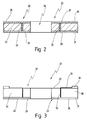
- an insulating film 22 is shown in cross section, enlarged and not to scale, as can be used with the temperature monitor 10 from FIG. 1.
- the insulating film 22 has a film 24, for example made of Teflon, Kapton, Nomex or the like.
- the film 24 is provided on both sides with resistance material 25, for example a thermistor material, a carbon film resistor or the like can be.
- resistance material 25 for example a thermistor material, a carbon film resistor or the like can be.
- an opening 26 is provided in the film 24, which is put over the movable contact part 17, as can be seen in FIG. 1.
- the insulating film 22 comes into contact with the cover part 12 via its upper resistance material 27 at its edge 28, while it lies on the shoulder 13 via its lower resistance material 29 at its edge 31 and is in electrical contact with the lower housing part 11 is located.
- vias 32 are provided which connect the upper resistance material 27 to the lower resistance material 29.
- the heating resistor 23 formed from the upper and lower resistance material 27, 29 is connected on the one hand to the cover part 12 and on the other hand to the lower housing part 11, so that it is connected in parallel to the bimetallic switching mechanism 15. In this way, the heating resistor 23 can provide the self-holding function of the new temperature monitor 10, which has already been discussed in detail.
- the resistance value can also be set via the distance of the plated-through holes 32 from the outer edges 28, 31, namely the more this plated-through hole lies at the edges 28, 31, the less the series connection from the two resistance areas, provided the other geometrical and electrical ones Properties are not changed.
- the through-contacts 32 can also be dispensed with, provided that that between the upper resistance material 27 and the lower resistance material 29 in the axial direction Direction measured resistance value is large enough to achieve the desired heating function when the bimetal switchgear is open.
- the heating resistor 23 is bridged by the latter anyway, so that its resistance value does not impair the function of the temperature monitor 10.
- the film 24 itself can be a PTC film 24 ', so that the upper and lower resistance material 27, 29 and the plated-through holes 32 can be dispensed with entirely.
- FIG. 3 shows a further exemplary embodiment of the new insulating film 22, as can be used with the temperature monitor 10 from FIG. 1.
- the film 24 here has 33 conductor tracks 34 on its upper side, which are connected via the plated-through holes 32 to a lower resistance material 29 on its lower side 35.
- the conductor tracks 34 extend essentially radially on the upper side 33 and open into a preferably circular conductor track 36 in the region of the edge 28.
- the heating resistor 23 is essentially formed by the lower resistance material 29, the conductor tracks 34, 36 and the Vias 32 are used only for the electrical connection between the lower resistance material 29 and the cover part 12.
- the lower resistance material 39 rests on the shoulder 13, so that the heating resistor 23 is also connected in parallel to the bimetallic switching mechanism 15 here.
- the conductor tracks 32, 34, 36 can also have tracks made of resistance material be, which can be arranged both on the top 33 and on the bottom 35.
- the heating resistor 23 is formed only by the resistance values of the resistance bands 32, 34, 36.
- the insulating film 22 of Fig. 3 is shown in a plan view, in which it can be seen that the resistance tracks 34, 36 cover the film 24 only in regions, the size of the cover, that is, the selected geometry, the resistance value of the heating resistor 23 determined.
- the insulating film 22 has resistance tracks 34, 36 both on its upper side 33 and on its lower side, as shown in FIG. 4.
- the film 24 can generally be made from a PTC thermistor material that has a non-specific positive temperature coefficient. However, it is also possible to directly use a PTC film with precisely set temperature-dependent resistance behavior as film 22, 24.
- the film 24 is made of conductive material and the conductor or resistance tracks 32, 34, 36 provide the resistance value of the heating resistor 23, then it may be necessary to close the free area 38 between the conductor tracks 34 with an intermediate layer of further insulating material 39 provided that on both sides of the insulating film 24 provides partial insulation to the lower housing part 11 or cover part 12 and, if the switching mechanism 15 is switched, possibly insulates the bimetallic disc 18 from the heating resistor 23.
Abstract
Description
- Die vorliegende Erfindung betrifft einen Temperaturwächter mit einem bei Übertemperatur schaltenden Bimetall-Schaltwerk und einem damit verschalteten Heizwiderstand, der im Sinne einer Selbsthaltefunktion wirkt.
- Ein derartiger Temperaturwächter ist beispielsweise aus der EP-A-0 284 916 bekannt.
- Der bekannte Temperaturwächter umfaßt ein von einem Deckelteil aus Kaltleitermaterial verschlossenes Gehäuseteil, in dem das Schaltwerk angeordnet ist. Das Bimetall-Schaltwerk umfaßt in bekannter Weise eine Bimetall-Schnappscheibe sowie eine Federscheibe, an der ein bewegliches Kontaktteil gehalten ist. Unterhalb der Ansprechtemperatur der Bimetall-Schnappscheibe wird das bewegliche Kontaktteil durch die Federscheibe gegen ein festes Kontaktteil am Deckel gedrückt, das sich nach Art eines Nietes durch den Deckel erstreckt und außen in einen Kopf übergeht. Das Gehäuseteil ist aus elektrisch leitendem Material gefertigt, so daß das Schaltwerk bei niedrigen Temperaturen eine leitende Verbindung zwischen dem Gehäuseteil und dem Kopf des festen Kontaktteiles herstellt. Der Deckel ist in leitender Verbindung sowohl mit dem festen Kontaktteil als auch mit dem Gehäuseteil, so daß er elektrisch parallel zu dem Schaltwerk geschaltet ist.
- Wenn das Schaltwerk jetzt infolge einer zu hohen Temperatur öffnet, fließt der Strom von dem festen Kontaktteil durch den durch den Deckel gebildeten Kaltleiterwiderstand zu dem Gehäuseteil, wodurch sich der Kaltleiterwiderstand erwärmt und das Schaltwerk geöffnet hält, auch wenn die das Schalten auslösende Übertemperatur nicht mehr vorhanden ist. Auf diese Weise wirkt der Kaltleiterwiderstand im Sinne einer Selbsthaltefunktion.
- In einem weiteren Ausführungsbeispiel aus dieser Druckschrift umfaßt der Deckel ein keramisches Trageteil, auf dem ein Kohlewiderstand angeordnet ist, der als Heizwiderstand für die Selbsthaltefunktion sorgt.
- Wenn der Deckel aus Kaltleitermaterial gefertigt ist, weist er nicht die erforderliche Druckstabilität auf, die im rauhen Alltagseinatz des bekannten Temperaturwächters häufig erforderlich ist. Derartige Temperaturwächter werden nämlich zur Temperaturüberwachung von Motoren, Heizwendeln etc. eingesetzt, wobei sie häufig starken mechanischen Belastungen infolge der mit dem Betrieb der zu schützenden Verbraucher verbundenen Vibrationen ausgesetzt sind. Dabei können auch starke Drücke auf den Deckel des Temperaturwächters ausgeübt werden.
- Wenn der Parallelwiderstand ein Kohlewiderstand ist, so kann der Deckel selbst zwar aus einem mechanisch stabileren Material bestehen, der Temperaturwächter weist jedoch andere Nachteile auf. Insbesondere bei einem Kohlewiderstand kann es nämlich vorkommen, daß das Bimetall-Schaltwerk infolge zu hoher Temperaturentwicklung des Kohlewiderstandes irreparabel zerstört wird. Dies ist bei einem Kaltleiterwiderstand aus parallel geschaltetem Heizwiderstand nicht möglich, da der Kaltleiterwiderstand infolge seines temperaturabhängigen Widerstandswertes, der mit steigender Temperatur steigt, in seiner Temperaturausbringung einstellbar ist, bzw. sich selbst regelt, so daß eine irreversible Schädigung des Schaltwerkes infolge von Übertemperaturen im Selbsthaltebetrieb vermieden wird.
- Aus der DE-OS-43 36 564 ist ein weiterer selbsthaltender Temperaturwächter bekannt, mit dem ein zweiter Heizwiderstand in Reihe geschaltet ist, der für eine Überstromempfindlichkeit des bekannten Temperaturwächters sorgt.
- Dieser bekannte Temperaturwächter umfaßt eine mit leitenden oder isolierenden Beschichtungen versehene Keramikträgerplatte, auf der ein gekapseltes Bimetall-Schaltwerk angeordnet ist, neben dem ein Kaltleiterbaustein sitzt, der elektrisch parallel zu dem Schaltwerk geschaltet ist, um für die Selbsthaltefunktion zu sorgen. Auf der Keramikträgerplatte ist weiter ein Dickschichtwiderstand angeordnet, der unter das Schaltwerk führt und mit diesem in Reihe geschaltet ist.
- Der bekannte Tempraturwächter wird in Reihe mit einem zu schützenden Verbraucher geschaltet, so daß er von dem Betriebsstrom des Verbrauchers durchflossen wird. Gleichzeitig steht dieser Temperaturwächter in bekannter Weise in thermischer Verbindung mit dem zu überwachenden Verbraucher. Erhöht sich der Betriebsstrom des Verbrauchers infolge eines Defektes in unzulässiger Weise, so heizt der in Reihe geschaltete Dickschichtwiderstand das Schaltwerk so weit auf, daß dieses öffnet, so daß der parallel geschaltete Kaltleiterwiderstand den Strom übernimmt. Wegen des hohen Widerstandes des Kaltleiterwiderstandes geht der Betriebsstrom des Verbrauchers jetzt auf ein unschädliches Maß zurück, das jedoch ausreicht, über die Ohm'sche Verlustleistung in dem Kaltleiterwiderstand eine Temperatur aufrecht zu erhalten, die das Schaltwerk öffnet. Selbstverständlich öffnet der bekannte Temperaturwächter auch dann, wenn der Verbraucher eine zu hohe Temperatur aufweist, woraufhin das Bimetall-Schaltwerk ebenfalls öffnet und der Kaltleiterwiderstand den Strom übernimmt und eine Temperatur aufrechterhält, die den Temperaturwächter offen bleiben läßt.
- Bei diesem Temperaturwächter ist von Nachteil, daß er eine relativ sperrige und große Bauweise aufweist, die insbesondere auf die Keramik-Trägerplatte zurückzuführen ist.
- Weiter ist aus der DE-OS-41 42 716 ein selbsthaltender Temperaturwächter in Miniaturausführung bekannt, bei dem ein parallel geschalteter Heizwiderstand und ein in Reihe geschalteter Heizwiderstand für eine Stromüberwachung vorhanden sind. Der Vorwiderstand ist als Ätz- oder Stanzteil bzw. als mit einem Widerstand bedruckte Folie in unmittelbarer Nähe sowie in thermischem und elektrischem Kontakt mit der Federscheibe des Bimetall-Schaltwerkes derart angeordnet, daß er unten im Bodenteil des Gehäuses zum Liegen kommt.
- Neben dem aufwendigen Zusammenbau des bekannten Temperaturwächters ist es weiter von Nachteil, daß die hier als Heizwiderstände verwendeten Ätz- oder Stanzteile hinsichtlich des Widerstandswertes nicht allzu genau und nur auf einen kleinen Widerstandsbereich gefertigt werden können. Ferner ist ein zusätzliches Isolierbauteil zwischen dem Gehäuseboden und dem Heizwiderstand und aus Gründen der Widerstandseinstellung meistens ein zusätzlicher, außen aufgesetzter weiterer hochohmiger Widerstand in Reihe zu dem erwähnten Vorwiderstand erforderlich, was insgesamt den Fertigungsaufwand und auch die Außenabmessungen vergrößert.
- Ausgehend von diesem Stand der Technik ist es Aufgabe der vorliegenden Erfindung, einen selbsthaltenden Temperaturwächter von der eingangs genannten Art zu schaffen, der die vorstehend genannten Nachteile überwindet. Insbesondere soll der neue Temperaturwächter bei einfachem Aufbau leicht zu montieren und allgemein preiswert herzustellen sein.
- Erfindungsgemäß wird diese Aufgabe dadurch gelöst, daß der Heizwiderstand an einer Folie ausgebildet ist, die vorzugsweise zur thermischen und/oder elektrischen Isolation vorgesehen ist.
- Die der Erfindung zugrundeliegende Aufgabe wird auf diese Weise vollkommen gelöst. Weil der Heizwiderstand jetzt an einer Folie ausgebildet ist, kann er bei kleinen Gesamtabmaßen an verschiedenen Stellen in einem das Schaltwerk aufnehmenden Gehäuse leicht untergebracht werden. Sollte der Temperaturwächter ein Gehäuse aus Metall umfassen, so können z.B. Deckel und Gehäuseunterteil durch die Folie, an der der Heizwiderstand ausgebildet ist, gleichzeitig elektrisch gegeneinander isoliert werden. Wenn das Gehäuse des Temperaturwächters dagegen aus Kunststoff oder einem ähnlichen elektrisch isolierenden Material gefertigt ist, so bewirkt die Folie hier eine thermische Isolation, damit ein hinreichender Teil der erzeugten Wärme sozusagen gespeichert werden kann, um die Selbsthaltefunktion zumindest für eine gewisse Zeit aufrecht zu erhalten. Die Folie kann aber auch andere Funktionen übernehmen, so kann sie z.B. gleichzeitig einen Schutz gegen Verschmutzungen oder ähnliches bieten, um einen in rauher und ggf. schmutzanfälliger Umgebung eingesetzten neuen Temperaturwächter gegen den Eintrag von die Funktion beeinträchtigenden Schmutzpartikeln zu isolieren.
- In einem Ausführungsbeispiel ist es dann bevorzugt, wenn der Temperaturwächter ein das Schaltwerk aufnehmendes Gehäuseunterteil aus leitfähigem Material, vorzugsweise aus Metall, sowie ein das Gehäuseunterteil verschließendes Deckelteil aus leitfähigem Material, vorzugsweise aus Metall, aufweist, und wenn die Folie gleichzeitig für eine erforderliche Isolation zwischen dem Gehäuseunterteil und dem Deckelteil sorgt.
- Hier ist von Vorteil, daß die hier sowieso benötigte Isolierfolie zwischen Gehäuseunterteil und Deckelteil jetzt gleichzeitig als Folie mit daran ausgebildetem Heizwiderstand vorgesehen werden kann. Derartige Temperaturwächter mit Metallgehäuse sind bspw. aus der DE-AS-21 21 802 bekannt. Die Kontaktierung des bekannten Temperaturwächters erfolgt einerseits über das Deckelteil und andererseits über das Gehäuseunterteil, so daß eine Isolierfolie zwischen diesen beiden Gehäuseteilen erforderlich ist. Durch die hier erwähnte Maßnahme kann also der bekannte Temperaturwächter auf überraschend einfache Weise mit einer Selbsthaltefunktion ausgestattet werden, wobei weiterhin die mechanisch sehr zuverlässige Konstruktion erhalten bleiben kann, die hohen Drücken standhält. Weiter ist von Vorteil, daß die Konstruktion und die Montage sowie die dafür vorgesehenen Vorrichtungen, wie z.B. Handhabungsapparate usw. nicht geändert werden müssen, vielmehr wird im üblichen Montageprozeß lediglich statt der bisher verwendeten Isolierfolie die Folie mit dem erfindungsgemäß daran vorgesehenen Heizwiderstand verwendet.
- In einem Ausführungsbeispiel ist es dann bevorzugt, wenn die Folie ein- oder beidseitig mit Widerstandsmaterial versehen, vorzusweise mit Widerstandsbahnen beschichtet oder bedruckt ist.
- Hier ist von Vorteil, daß der Widerstandswert je nach den gewünschten Gegebenheiten angepaßt werden kann, indem entweder eine einseitig oder eine beidseitig mit Widerstandsmaterial versehene Folie verwendet wird. Durch die Geometrie der Widerstandsbahnen kann der Widerstandswert weiter eingestellt werden.
- Weiter ist es bevorzugt, wenn die Folie ein Widerstandsmaterial aus Kaltleitermaterial aufweist.
- Hier ist von Vorteil, daß auch bei dem neuen Heizwiderstand an der Folie die eingangs erwähnten Vorteile des Kaltleiterwiderstandes realisiert werden können, also der Schutz vor Übertemperaturen durch die Selbstregelung.
- Dabei ist es bevorzugt, wenn die Folie zumindest an einer Stelle durchkontaktiert ist, so daß das Widerstandsmaterial auf beiden Seiten der Folie elektrisch miteinander verbunden ist.
- Hier ist von Vorteil, daß sich eine einfache Kontaktierung zu Deckelteil und Gehäuseunterteil ergibt. Die Folie stellt sozusagen zwei in Reihe geschaltete Bereiche aus Widerstandsmaterial und/oder Leitermaterial dar, die durch einfaches Einlegen in das Gehäuseunterteil mit diesem in Kontakt gelangen. Das Deckelteil wird dann auf die Folie aufgelegt, wodurch der zweite Kontakt hergestellt wird. In üblicher Weise werden dann die Ränder des Gehäuseunterteiles umgebördelt, so daß das Deckelteil fest an dem Gehäuseunterteil gehalten wird. Der Heizwiderstand ist jetzt parallel zu dem Bimetall-Schaltwerk geschaltet, das wie eingangs erwähnt, einerseits über die Federscheibe mit dem Gehäuseunterteil und andererseits über das bewegliche Kontaktteil mit dem Deckel in Verbindung steht, wenn das Schaltwerk geschlossen ist.
- Weiter ist es bevorzugt, wenn die Folie eine Heizfolie ist, die eine isolierende Kunststoffolie mit als Heizwiderstand dienenden Leiterbahnen aufweist.
- Auch diese Maßnahme ist im Hinblick auf eine einfache Kontaktierung bevorzugt, die Heizfolie wird genauso wie die zuvor erwähnte Folie als Isolierfolie verwendet. Die Leiterbahnen sind dabei so angeordnet, daß sie sowohl mit dem Deckelteil als auch mit dem Gehäuseunterteil in Verbindung geraten, wenn der Temperaturwächter auf übliche Weise zusammengebaut wird.
- Dabei ist es ferner bevorzugt, wenn die Folie eine Kaltleiterfolie, vorzugsweise eine PTC-Folie ist.
- Hier ist von Vorteil, daß die Folie insgesamt als Kaltleiterwiderstand ausgebildet sein kann, wodurch sich die Kontaktierung zu Deckelteil und Gehäuseunterteil sehr einfach gestaltet.
- Andererseits ist es bevorzugt, wenn die Folie bereichsweise mit Widerstandsmaterial versehen ist.
- Hier ist von Vorteil, daß durch die Wahl der Größe und ggf. Geometrie des Widerstandsmaterials der Widerstandswert des Heizwiderstandes genau eingestellt werden kann.
- Ferner ist es bevorzugt, wenn die Folie einseitig mit Widerstandsmaterial versehen ist und auf der anderen Seite der Kontaktierung dienende Leiterbahnen aufweist.
- Dies ist eine andere vorteilhafte Weise, wie die auch der elektrischen Isolation zwischen Deckelteil und Gehäuseunterteil dienende Folie ohne einen Kurzschluß zu bewirken für eine Parallelschaltung des Heizwiderstandes zu dem Bimetall-Schaltwerk sorgen kann.
- Allgemein ist es bevorzugt, wenn die Folie ggf. unter Zwischenlage von weiterem Isoliermaterial zwischen Gehäuseunterteil und Deckelteil eingeklemmt wird.
- Hier ist von Vorteil, daß sich der neue Temperaturwächter nicht nur leicht montieren läßt, sondern daß auch auf einfache Weise einerseits ein Kurzschluß vermieden und andererseits eine Kontaktierung des Heizwiderstandes bewirkt wird.
- Weitere Vorteile ergeben sich aus der Beschreibung und der beigefügten Zeichnung.
- Es versteht sich, daß die vorstehend genannten und die nachstehend noch zu erläuternden Merkmale nicht nur in der jeweils angegebenen Kombination, sondern auch in anderen Kombinationen oder in Alleinstellung verwendbar sind, ohne den Rahmen der vorstehenden Erfindung zu verlassen.
- Die Erfindung ist in der Zeichnung dargestellt und wird in der nachfolgenden Beschreibung näher erläutert. Es zeigen:
- Fig. 1
- einen neuen Temperaturwächter in einer geschnittenen Seitenansicht, bei dem an der Isolierfolie ein aus Übersichtlichkeitsgründen nicht dargestellter Heizwiderstand ausgebildet ist;
- Fig. 2
- eine für den Einbau in den Temperaturwächter aus Fig. 1 geeignete Isolierfolie, vor dem Einbau, vergrößert und nicht maßstabsgerecht;
- Fig. 3
- in einer Darstellung wie Fig. 2 ein weiteres Ausführungsbeispiel der mit einem Heizwiderstand versehenen Isolierfolie;
- Fig. 4
- eine Draufsicht auf die Isolierfolie aus Fig. 3.
- In Fig. 1 ist in einem Axialschnitt eine Ausführungsform des neuen Temperaturwächters 10 gezeigt. Der Temperaturwächter 10 umfaßt ein topfförmiges Gehäuseunterteil 11 sowie ein das Gehäuseunterteil 11 verschließendes Deckelteil 12, das auf einer umlaufenden Schulter 13 des Gehäuseteiles 11 aufliegt. Der Temperaturwächter 10 ist über einen Bördelrand 14 des Gehäuseunterteiles 11 verschlossen, der das Deckelteil 12 auf die umlaufende Schulter 13 drückt.
- In dem Inneren des Gehäuseunterteiles 11 befindet sich ein Bimetall-Schaltwerk 15, das von üblicher Konstruktion ist. Es umfaßt eine Federscheibe 16, die ein bewegliches Kontaktteil 17 trägt, über das eine Bimetall-Schnappscheibe 18 gestülpt ist. Die Federscheibe 16 stützt sich an einem Boden des topfförmigen Gehäuseunterteiles 11 ab und spannt so das bewegliche Kontaktteil 17 gegen ein festes Kontaktteil 20 vor, das innen an dem Deckelteil 12 vorgesehen ist.
- Bei diesem Temperaturwächter 10 sind Gehäuseunterteil 11 sowie Deckelteil 12 aus leitfähigem Material, vorzugsweise aus Metall gefertigt, so daß eine Isolierfolie 22 vorgesehen ist, die das Deckelteil 12 gegenüber dem Gehäuseunterteil 11 isoliert. Die Kontaktierung des Temperaturwächters 10 erfolgt einerseits über das Deckelteil 12 und andererseits über das Gehäuseunterteil 11, wie das an sich bekannt ist.
- In dem in Fig. 1 gezeigten Zustand weist das Schaltwerk 15 eine Temperatur unterhalb seiner Ansprechtemperatur auf, so daß es sich im geschlossenen Zustand befindet, in dem es für eine leitende Verbindung zwischen dem festen Kontaktteil 20 und damit dem Deckelteil 12 sowie dem Boden 19 und damit dem Gehäuseunterteil 11 sorgt.
- Wird die Temperatur des Schaltwerkes 15 jetzt erhöht, so schnappt die Bimetall-Schnappscheibe 18 plötzlich von der gezeigten konvexen Form in eine konkave Form um und stützt sich an der Unterseite des Deckelteiles 12 derart ab, daß es das bewegliche Kontaktteil gegen die Kraft der Federscheibe 18 von dem festen Kontaktteil 20 abhebt.
- Insoweit ist die Konstruktion des neuen Temperaturwächters 10 bekannt, der wegen seines aus Metall gefertigten Gehäuses eine hohe Druckstabilität aufweist.
- Erfindungsgemäß ist an der Isolierfolie 22 jetzt ein in Fig. 1 der Übersichtlichkeit halber nicht gezeigter Heizwiderstand 23 ausgebildet, der auf noch zu beschreibende Weise parallel zu dem Bimetall-Schaltwerk 15 geschaltet ist. Solange sich das Bimetall-Schaltwerk 15 in der in Fig. 1 gezeigten geschlossenen Stellung befindet, ist der Heizwiderstand 23 überbrückt und zeigt keine Wirkung. Wenn sich das Bimetall-Schaltwerk infolge einer Übertemperatur jedoch öffnet, so übernimmt der Heizwiderstand 23 einen Teil des bisher durch den Temperaturwächter 10 geflossenen Stromes, der den Heizwiderstand 23 so weit aufheizt, daß im Inneren des Temperaturwächters 10 eine Temperatur erzeugt wird, die auch bei Abfall der das Schalten bewirkenden äußeren Übertemperatur ausreicht, um das Bimetall-Schaltwerk 15 zumindest noch für eine gewisse Weile in dem geöffneten Zustand zu halten. Die Isolierfolie 22 kann dabei so ausgebildet sein, daß sie einen zu schnellen Wärmeverlust aus dem Inneren des Temperaturwächters 10 verhindert. So kann es beispielsweise vorgesehen sein, daß das Gehäuseunterteil 11 und Deckelteil 12 aus Kunststoff oder einem ähnlichen nicht leitenden Material besteht, so daß die Isolierfolie 22 an sich für die Funktion nicht erforderlich ist. Selbstverständlich ist in einem solchen Falle das feste Kontaktteil 20 bspw. nach Art eines Nietes nach außen durchkontaktiert, während andererseits über den Boden 19 eine elektrische Verbindung nach außen hergestellt wird. Aus Gründen der Übersichtlichkeit ist diese Alternative in Fig. 1 nicht weiter dargestellt.
- Obwohl - wie gesagt - die Isolierfolie 22 hier nicht der elektrischen Isolation wegen vorgesehen sein muß, weist sie doch den Vorteil auf, daß sie eine weitere thermische Isolation des Inneren des Temperaturwächters 10 bewirkt, so daß die in dem Inneren des Temperaturwächters 10 herrschende Temperatur sich nicht zu schnell abbaut. Der Heizwiderstand 23 kann in diesem Falle so bemessen sein, daß er allein über lange Zeit die erforderliche Temperatur in dem Inneren des Temperaturwächters 10 nicht halten kann, jedoch dazu beiträgt, daß diese Temperatur sich nur so langsam abbaut, daß die gewünschte Einschaltverzögerung erreicht wird. Selbstverständlich kann diese Zusatzfunktion der thermischen Isolierung von der Isolierfolie 22 auch ausgeübt werden, wenn Deckelteil 12 und Gehäuseunterteil 11 aus Metall sind.
- In beiden oben erwähnten Ausführungsbeispielen weist die Isolierfolie 22 also zwei Funktionen auf, zum einen dient sie der elektrischen und/oder thermischen Isolation und zum anderen ist an ihr der Heizwiderstand 23 ausgebildet, der die Selbsthaltefunktion bewirkt oder aber unterstützt.
- Ein besonderer Vorteil des neuen Temperaturwächters 10 liegt darin, daß bekannte Konstruktionen, die bereits eine Isolierfolie aus den oben genannten Gründen zur elektrischen Isolation verwenden, vollständig beibehalten werden können, die Isolierfolie 22 muß lediglich zusätzlich mit einem Heizwiderstand 23 versehen werden. Das bedeutet aber, daß in dem üblichen Fertigungsprozeß lediglich die bisher verwendete reine Isolierfolie gegen eine erfindungsgemäße Isolierfolie mit Heizwiderstand ausgetauscht werden muß, so daß überhaupt keine Rüstkosten für die Produktionsvorrichtungen auftreten. Der neue Temperaturwächter 10 weist alle die bekannten und gewünschten mechanischen und elektrischen Eigenschaften auf, die im Markt bereits eingeführt sind, und erhält jetzt auf diese extrem einfache Weise zusätzlich eine Selbsthaltefunktion.
- Wie dieser Heizwiderstand 23 an der Isolierfolie 22 ausgebildet werden kann, wird jetzt beispielhaft im Zusammenhang mit den Figuren 2 bis 4 erörtert.
- In Fig. 2 ist vergrößert und nicht maßstabsgerecht eine Isolierfolie 22 im Querschnitt dargestellt, wie sie bei dem Temperaturwächter 10 aus Fig. 1 eingesetzt werden kann.
- Die Isolierfolie 22 weist als Träger eine Folie 24 bspw. aus Teflon, Kapton, Nomex oder ähnlichem auf. Auf beiden Seiten ist die Folie 24 mit Widerstandsmaterial 25 versehen, das z.B. ein Kaltleitermaterial, ein Kohleschichtwiderstand oder ähnliches sein kann. In bekannter Weise ist in der Folie 24 eine Öffnung 26 vorgesehen, die über das bewegliche Kontaktteil 17 gestülpt wird, wie dies in Fig. 1 erkennbar ist.
- Die Isolierfolie 22 gelangt beim Einbau in den Temperaturwächter 10 über ihr oberes Widerstandsmaterial 27 an dessen Rand 28 mit dem Deckelteil 12 in Kontakt, während sie über ihr unteres Widerstandsmaterial 29 an dessen Rand 31 auf der Schulter 13 aufliegt und sich in elektrischem Kontakt mit dem Gehäuseunterteil 11 befindet.
- Da in dem gezeigten Ausführungsbeispiel die Folie 24 selbst isolierend ist, sind Durchkontaktierungen 32 vorgesehen, die das obere Widerstandsmaterial 27 mit dem unteren Widerstandsmaterial 29 verbinden. Auf diese Weise ist der aus dem oberen und dem unteren Widerstandsmaterial 27, 29 gebildete Heizwiderstand 23 einerseits mit dem Deckelteil 12 und andererseits mit dem Gehäuseunterteil 11 verbunden, so daß er parallel zu dem Bimetall-Schaltwerk 15 geschaltet ist. Auf diese Weise kann der Heizwiderstand 23 für die bereits ausführlich diskutierte Selbsthaltefunktion des neuen Temperaturwächters 10 sorgen.
- Über den Abstand der Durchkontaktierungen 32 von den äußeren Rändern 28, 31 läßt sich außerdem der Widerstandswert einstellen, je mehr nämlich diese Durchkontaktierung an den Rändern 28, 31 liegt, desto geringer ist die Reihenschaltung aus den beiden Widerstandsbereichen, vorausgesetzt, die sonstigen geometrischen und elektrischen Eigenschaften werden nicht verändert.
- Sollte die Folie 24 leitend sein oder aber selbst einen gewissen Widerstand aufweisen, so kann auf die Durchkontaktierungen 32 auch verzichtet werden, sofern der zwischen oberem Widerstandsmaterial 27 und unterem Widerstandsmaterial 29 in axialer Richtung gemessene Widerstandswert groß genug ist, um die gewünschte Heizfunktion zu erreichen, wenn das Bimetall-Schaltwerk geöffnet ist. Bei geschlossenem Bimetall-Schaltwerk 15 ist der Heizwiderstand 23 sowieso durch letzteres überbrückt, so daß sein Widerstandswert die Funktion des Temperaturwächters 10 nicht beeinträchtigt.
- In einem in Fig. 2 nicht gezeigten Ausführungsbeispiel kann die Folie 24 selbst eine PTC-Folie 24' sein, so daß auf das obere und das untere Widerstandsmaterial 27, 29 sowie auf die Durchkontaktierungen 32 ganz verzichtet werden kann.
- In Fig. 3 ist ein weiteres Ausführungsbeispiel der neuen Isolierfolie 22 gezeigt, wie sie bei dem Temperaturwächter 10 aus Fig. 1 eingesetzt werden kann.
- Die Folie 24 weist hier an ihrer Oberseite 33 Leiterbahnen 34 auf, die über die Durchkontaktierungen 32 mit unterem Widerstandsmaterial 29 an ihrer Unterseite 35 verbunden sind. Die Leiterbahnen 34 erstrecken sich im wesentlichen radial auf der Oberseite 33 und münden in eine vorzugsweise kreisförmige Leiterbahn 36 im Bereich des Randes 28. Bei dieser Isolierfolie 22 wird der Heizwiderstand 23 im wesentlichen durch das untere Widerstandsmaterial 29 gebildet, die Leiterbahnen 34, 36 sowie die Durchkontaktierungen 32 dienen lediglich der elektrischen Verbindung zwischen dem unteren Widerstandsmaterial 29 und dem Deckelteil 12. Am Rand 31 liegt das untere Widerstandsmaterial 39 wieder auf der Schulter 13 auf, so daß auch hier der Heizwiderstand 23 parallel zu dem Bimetall-Schaltwerk 15 geschaltet ist.
- In Abwandlung des Ausführungsbeispieles aus Fig. 3 können die Leiterbahnen 32, 34, 36 auch Bahnen aus Widerstandsmaterial sein, die sowohl an der Oberseite 33 als auch an der Unterseite 35 angeordnet sein können. In diesem Falle wird der Heizwiderstand 23 lediglich durch die Widerstandswerte der Widerstandsbannen 32, 34, 36 gebildet. In einem solchen Falle spricht man von einer Heizfolie 37, bei der eine Isolierfolie 24 mit Widerstandsbahnen 32, 34, 36 versehen ist.
- In Fig. 4 ist die Isolierfolie 22 aus Fig. 3 in einer Draufsicht gezeigt, in der zu sehen ist, daß die Widerstandsbahnen 34, 36 die Folie 24 nur bereichsweise abdecken, wobei das Maß der Abdeckung, also die gewählte Geometrie den Widerstandswert des Heizwiderstandes 23 bestimmt.
- Selbstverständlich kann es in Abwandlung des Ausführungsbeispieles gemäß Fig. 4 auch vorgesehen sein, daß die Isolierfolie 22 sowohl an ihrer Oberseite 33 als auch an ihrer Unterseite 35 Widerstandsbahnen 34, 36 aufweist, wie sie in Fig. 4 gezeigt sind.
- Die Folie 24 kann allgemein aus einem Kaltleitermaterial gefertigt sein, das unspezifisch einen positiven Temperaturkoeffizienten aufweist. Es ist jedoch auch möglich, als Folie 22, 24 direkt eine PTC-Folie mit genau eingestelltem temperaturabhängigen Widerstandsverhalten zu verwenden.
- Wenn die Folie 24 aus leitfähigem Material besteht, und die Leiter- oder Widerstandsbahnen 32, 34, 36 für den Widerstandswert des Heizwiderstandes 23 sorgen, dann kann es erforderlich sein, den freien Bereich 38 zwischen den Leiterbahnen 34 mit einer Zwischenlage von weiterem Isoliermaterial 39 zu versehen, das beidseits der Isolierfolie 24 für eine teilweise Isolation zu dem Gehäuseunterteil 11 bzw. Deckelteil 12 sorgt und bei geschaltetem Schaltwerk 15 die Bimetallscheibe 18 gegenüber dem Heizwiderstand 23 ggf. isoliert.
Claims (10)
- Temperaturwächter mit einem bei Übertemperatur schaltenden Bimetall-Schaltwerk (15) und einem damit verschalteten Heizwiderstand (23), der im Sinne einer Selbsthaltefunktion wirkt, dadurch gekennzeichnet, daß der Heizwiderstand (23) an einer Folie (22, 24) ausgebildet ist, die vorzugsweise zur thermischen und/oder elektrischen Isolation vorgesehen ist.
- Temperaturwächter nach Anspruch 1, dadurch gekennzeichnet, daß ein das Schaltwerk (15) aufnehmendes Gehäuseunterteil (11) aus leitfähigem Material, vorzugsweise aus Metall, sowie ein das Gehäuseunterteil (11) verschließendes Deckelteil (12) aus leitfähigem Material, vorzugsweise aus Metall, vorgesehen ist, und daß die Folie (22, 24) gleichzeitig für eine erforderliche Isolation zwischen Gehäuseunterteil (11) und Deckelteil (12) sorgt.
- Temperaturwächter nach Anspruch 1 oder 2, dadurch gekennzeichnet, daß die Folie (22, 24) ein- oder beidseitig mit Widerstandsmaterial (25, 27, 29; 34, 36) versehen, vorzugsweise mit Widerstandsbahnen (34, 36) beschichtet oder bedruckt ist.
- Temperaturwächter nach einem der Ansprüche 1 bis 3, dadurch gekennzeichnet, daß die Folie (22, 24) ein Widerstandsmaterial (25) aus Kaltleitermaterial aufweist.
- Temperaturwächter nach einem der Ansprüche 1 bis 4, dadurch gekennzeichnet, daß die Folie (22, 24) zumindest an einer Stelle (32) durchkontaktiert ist, so daß Widerstandsmaterial (27, 29; 34, 36) auf beiden Seiten (33, 35) der Folie (22, 24) elektrisch miteinander verbunden ist.
- Temperaturwächter nach einem der Ansprüche 1 bis 5, dadurch gekennzeichnet, daß die Folie (22, 24) eine Heizfolie (37) ist, die eine isolierende Kunststoffolie (24) mit als Heizwiderstand (23) dienenden Leiterbahnen (34, 36) aufweist.
- Temperaturwächter nach einem der Ansprüche 1 bis 6, dadurch gekennzeichnet, daß die Folie (22, 24) eine Kaltleiterfolie, vorzugsweise eine PTC-Folie ist.
- Temperaturwächter nach einem der Ansprüche 1 bis 7, dadurch gekennzeichnet, daß die Folie (22, 24) bereichsweise mit Widerstandsmaterial (25) versehen ist.
- Temperaturwächter nach einem der Ansprüche 1 bis 8, dadurch gekennzeichnet, daß die Folie (22, 24) einseitig mit Widerstandsmaterial (25) versehen ist und auf der anderen Seite der Kontaktierung dienende Leiterbahnen (34, 36) aufweist.
- Temperaturwächter nach einem der Ansprüche 1 bis 9, dadurch gekennzeichnet, daß die Folie (22, 24) ggf. unter Zwischenlage von weiterem Isoliermaterial zwischen Gehäuseunterteil (11) und Deckelteil (12) eingeklemmt wird.
Applications Claiming Priority (2)
| Application Number | Priority Date | Filing Date | Title |
|---|---|---|---|
| DE19514853 | 1995-04-26 | ||
| DE19514853A DE19514853C2 (de) | 1995-04-26 | 1995-04-26 | Temperaturwächter mit einem bei Übertemperatur schaltenden Bimetall-Schaltwerk |
Publications (3)
| Publication Number | Publication Date |
|---|---|
| EP0740323A2 true EP0740323A2 (de) | 1996-10-30 |
| EP0740323A3 EP0740323A3 (de) | 1998-04-22 |
| EP0740323B1 EP0740323B1 (de) | 2002-04-03 |
Family
ID=7760123
Family Applications (1)
| Application Number | Title | Priority Date | Filing Date |
|---|---|---|---|
| EP96100742A Expired - Lifetime EP0740323B1 (de) | 1995-04-26 | 1996-01-19 | Temperaturwächter mit einem bei Übertemperatur schaltenden Bimetall-Schaltwerk |
Country Status (7)
| Country | Link |
|---|---|
| US (1) | US5721525A (de) |
| EP (1) | EP0740323B1 (de) |
| AT (1) | ATE215732T1 (de) |
| DE (2) | DE19514853C2 (de) |
| DK (1) | DK0740323T3 (de) |
| ES (1) | ES2174984T3 (de) |
| PT (1) | PT740323E (de) |
Cited By (2)
| Publication number | Priority date | Publication date | Assignee | Title |
|---|---|---|---|---|
| EP2775495A1 (de) * | 2013-03-04 | 2014-09-10 | Marcel P. Hofsaess | Temperaturabhängiger Schalter mit Isolierscheibe |
| DE102022134379B3 (de) | 2022-12-21 | 2024-02-08 | Marcel P. HOFSAESS | Temperaturabhängiger Schalter |
Families Citing this family (10)
| Publication number | Priority date | Publication date | Assignee | Title |
|---|---|---|---|---|
| DE19639942C2 (de) * | 1996-09-27 | 1999-07-01 | Siemens Matsushita Components | Thermische Sicherung |
| DE19752581C2 (de) * | 1997-11-27 | 1999-12-23 | Marcel Hofsaes | Schalter mit einem temperaturabhängigen Schaltwerk |
| DE19827113C2 (de) * | 1998-06-18 | 2001-11-29 | Marcel Hofsaes | Temperaturabhängiger Schalter mit Stromübertragungsglied |
| US6229121B1 (en) * | 1999-07-23 | 2001-05-08 | Industrial Technology Research Institute | Integrated thermal buckling micro switch with electric heater and sensor |
| EP1508909A4 (de) * | 2002-05-07 | 2007-08-01 | Ubukata Ind Co Ltd | Thermische schutzvorrichtung |
| US20080055038A1 (en) * | 2006-08-31 | 2008-03-06 | Honeywell International Inc. | Thermal switch strike pin |
| KR20110005879A (ko) * | 2008-04-18 | 2011-01-19 | 타이코 일렉트로닉스 저팬 지.케이. | 회로 보호 디바이스 |
| US8547196B2 (en) * | 2008-05-30 | 2013-10-01 | Ubukata Industries Co., Ltd. | Thermally responsive switch |
| DE102013108508A1 (de) | 2013-08-07 | 2015-02-12 | Thermik Gerätebau GmbH | Temperaturabhängiger Schalter |
| DE102019125453A1 (de) * | 2019-09-20 | 2021-03-25 | Marcel P. HOFSAESS | Temperaturabhängiger Schalter |
Citations (3)
| Publication number | Priority date | Publication date | Assignee | Title |
|---|---|---|---|---|
| EP0284916A2 (de) * | 1987-03-31 | 1988-10-05 | Ulrika Hofsäss | Temperaturwächter mit einem Gehäuse |
| EP0507425A1 (de) * | 1991-04-05 | 1992-10-07 | Uchiya Thermostat Co. | Elektrothermisches Relais mit Schichtheizelement |
| DE9320737U1 (de) * | 1993-10-13 | 1995-01-05 | Eaw Relaistechnik Gmbh | Thermoschalter mit Bimetallschnappscheibe und elektrischer/thermischer Verhinderung des automatischen Rückschnappens der Bimetallschnappscheibe |
Family Cites Families (7)
| Publication number | Priority date | Publication date | Assignee | Title |
|---|---|---|---|---|
| DE2121802C3 (de) * | 1971-05-03 | 1974-10-24 | Thermik-Geraetebau Gmbh + Co, 7530 Pforzheim | Temperaturwächter |
| DE3644514A1 (de) * | 1986-12-24 | 1988-07-07 | Inter Control Koehler Hermann | Bimetallschalter |
| US4878038A (en) * | 1987-12-07 | 1989-10-31 | Tsai James T | Circuit protection device |
| DE4142716C2 (de) * | 1991-12-21 | 1997-01-16 | Microtherm Gmbh | Thermoschalter |
| DE4206157A1 (de) * | 1992-02-28 | 1993-09-16 | Hofsass P | Thermoschalter |
| DE9214940U1 (de) * | 1992-11-03 | 1992-12-17 | Thermik Geraetebau Gmbh, 7530 Pforzheim, De | |
| DE4335639A1 (de) * | 1993-10-13 | 1995-04-20 | Eaw Relaistechnik Gmbh | Thermoschalter mit Bimetallschnappscheibe und elektrischer/thermischer Verhinderung des automatischen Rückschnappens der Bimetallschnappscheibe |
-
1995
- 1995-04-26 DE DE19514853A patent/DE19514853C2/de not_active Expired - Fee Related
-
1996
- 1996-01-19 EP EP96100742A patent/EP0740323B1/de not_active Expired - Lifetime
- 1996-01-19 ES ES96100742T patent/ES2174984T3/es not_active Expired - Lifetime
- 1996-01-19 AT AT96100742T patent/ATE215732T1/de active
- 1996-01-19 DK DK96100742T patent/DK0740323T3/da active
- 1996-01-19 DE DE59608984T patent/DE59608984D1/de not_active Expired - Lifetime
- 1996-01-19 PT PT96100742T patent/PT740323E/pt unknown
- 1996-04-24 US US08/636,944 patent/US5721525A/en not_active Expired - Lifetime
Patent Citations (3)
| Publication number | Priority date | Publication date | Assignee | Title |
|---|---|---|---|---|
| EP0284916A2 (de) * | 1987-03-31 | 1988-10-05 | Ulrika Hofsäss | Temperaturwächter mit einem Gehäuse |
| EP0507425A1 (de) * | 1991-04-05 | 1992-10-07 | Uchiya Thermostat Co. | Elektrothermisches Relais mit Schichtheizelement |
| DE9320737U1 (de) * | 1993-10-13 | 1995-01-05 | Eaw Relaistechnik Gmbh | Thermoschalter mit Bimetallschnappscheibe und elektrischer/thermischer Verhinderung des automatischen Rückschnappens der Bimetallschnappscheibe |
Cited By (2)
| Publication number | Priority date | Publication date | Assignee | Title |
|---|---|---|---|---|
| EP2775495A1 (de) * | 2013-03-04 | 2014-09-10 | Marcel P. Hofsaess | Temperaturabhängiger Schalter mit Isolierscheibe |
| DE102022134379B3 (de) | 2022-12-21 | 2024-02-08 | Marcel P. HOFSAESS | Temperaturabhängiger Schalter |
Also Published As
| Publication number | Publication date |
|---|---|
| ES2174984T3 (es) | 2002-11-16 |
| DE59608984D1 (de) | 2002-05-08 |
| DE19514853A1 (de) | 1996-11-07 |
| US5721525A (en) | 1998-02-24 |
| DK0740323T3 (da) | 2002-06-17 |
| ATE215732T1 (de) | 2002-04-15 |
| PT740323E (pt) | 2002-07-31 |
| EP0740323B1 (de) | 2002-04-03 |
| DE19514853C2 (de) | 1997-02-27 |
| EP0740323A3 (de) | 1998-04-22 |
Similar Documents
| Publication | Publication Date | Title |
|---|---|---|
| DE4428226C1 (de) | Temperaturwächter | |
| DE102008048554B3 (de) | Temperaturabhängiger Schalter | |
| DE19604939C2 (de) | Schalter mit einem temperaturabhängigen Schaltwerk | |
| DE19527253B4 (de) | Nach dem Baukastenprinzip aufgebauter Temperaturwächter | |
| EP0756301B1 (de) | Temperaturwächter | |
| DE102013102006B4 (de) | Temperaturabhängiger Schalter | |
| EP0920044B1 (de) | Schalter mit einem temperaturabhängigen Schaltwerk | |
| EP2874171B1 (de) | Temperaturabhängiges schaltwerk | |
| EP0794546B1 (de) | Schalter mit einem temperaturabhängigen Schaltwerk | |
| DE4142716C2 (de) | Thermoschalter | |
| EP0740323B1 (de) | Temperaturwächter mit einem bei Übertemperatur schaltenden Bimetall-Schaltwerk | |
| WO2008113489A1 (de) | Temperaturabhängiger schalter und dafür vorgesehenes schaltwerk | |
| DE19636640C2 (de) | Schalter mit einem Sicherheitselement | |
| DE102011119632B3 (de) | Temperaturabhängiges Schaltwerk | |
| DE102011119637B4 (de) | Temperaturabhängiger Schalter mit einem temperaturabhängigen Schaltwerk sowie Verfahren zum Herstellen eines solchen Schalters | |
| EP0858091B1 (de) | Vorrichtung zum Schützen eines Gerätes | |
| DE19546004C2 (de) | Schalter mit einem bei Übertemperatur schaltenden Schaltwerk | |
| EP0887827B1 (de) | Schalter mit einem temperatur-abhängigen Schaltwerk | |
| EP0778597B1 (de) | Schalter mit einem bei Übertemperatur schaltenden Schaltwerk | |
| DE102019111279B4 (de) | Temperaturabhängiger Schalter | |
| DE102022134379B3 (de) | Temperaturabhängiger Schalter | |
| DE102011122890A1 (de) | Temperaturabhängiges Schaltwerk |
Legal Events
| Date | Code | Title | Description |
|---|---|---|---|
| PUAI | Public reference made under article 153(3) epc to a published international application that has entered the european phase |
Free format text: ORIGINAL CODE: 0009012 |
|
| AK | Designated contracting states |
Kind code of ref document: A2 Designated state(s): AT BE CH DE DK ES FR GB IE IT LI NL PT SE |
|
| PUAL | Search report despatched |
Free format text: ORIGINAL CODE: 0009013 |
|
| AK | Designated contracting states |
Kind code of ref document: A3 Designated state(s): AT BE CH DE DK ES FR GB IE IT LI NL PT SE |
|
| RAP1 | Party data changed (applicant data changed or rights of an application transferred) |
Owner name: HOFSAESS, MARCEL |
|
| 17P | Request for examination filed |
Effective date: 19980507 |
|
| 17Q | First examination report despatched |
Effective date: 19991118 |
|
| GRAG | Despatch of communication of intention to grant |
Free format text: ORIGINAL CODE: EPIDOS AGRA |
|
| GRAG | Despatch of communication of intention to grant |
Free format text: ORIGINAL CODE: EPIDOS AGRA |
|
| GRAH | Despatch of communication of intention to grant a patent |
Free format text: ORIGINAL CODE: EPIDOS IGRA |
|
| GRAH | Despatch of communication of intention to grant a patent |
Free format text: ORIGINAL CODE: EPIDOS IGRA |
|
| REG | Reference to a national code |
Ref country code: GB Ref legal event code: IF02 |
|
| GRAA | (expected) grant |
Free format text: ORIGINAL CODE: 0009210 |
|
| AK | Designated contracting states |
Kind code of ref document: B1 Designated state(s): AT BE CH DE DK ES FR GB IE IT LI NL PT SE |
|
| REF | Corresponds to: |
Ref document number: 215732 Country of ref document: AT Date of ref document: 20020415 Kind code of ref document: T |
|
| REG | Reference to a national code |
Ref country code: CH Ref legal event code: NV Representative=s name: TROESCH SCHEIDEGGER WERNER AG Ref country code: CH Ref legal event code: EP |
|
| REF | Corresponds to: |
Ref document number: 59608984 Country of ref document: DE Date of ref document: 20020508 |
|
| REG | Reference to a national code |
Ref country code: IE Ref legal event code: FG4D Free format text: GERMAN |
|
| REG | Reference to a national code |
Ref country code: DK Ref legal event code: T3 |
|
| GBT | Gb: translation of ep patent filed (gb section 77(6)(a)/1977) |
Effective date: 20020626 |
|
| REG | Reference to a national code |
Ref country code: PT Ref legal event code: SC4A Free format text: AVAILABILITY OF NATIONAL TRANSLATION Effective date: 20020412 |
|
| ET | Fr: translation filed | ||
| REG | Reference to a national code |
Ref country code: ES Ref legal event code: FG2A Ref document number: 2174984 Country of ref document: ES Kind code of ref document: T3 |
|
| PLBE | No opposition filed within time limit |
Free format text: ORIGINAL CODE: 0009261 |
|
| STAA | Information on the status of an ep patent application or granted ep patent |
Free format text: STATUS: NO OPPOSITION FILED WITHIN TIME LIMIT |
|
| 26N | No opposition filed |
Effective date: 20030106 |
|
| PGFP | Annual fee paid to national office [announced via postgrant information from national office to epo] |
Ref country code: PT Payment date: 20110117 Year of fee payment: 16 Ref country code: SE Payment date: 20110113 Year of fee payment: 16 |
|
| PGFP | Annual fee paid to national office [announced via postgrant information from national office to epo] |
Ref country code: CH Payment date: 20120123 Year of fee payment: 17 Ref country code: FR Payment date: 20120206 Year of fee payment: 17 Ref country code: IE Payment date: 20120124 Year of fee payment: 17 |
|
| PGFP | Annual fee paid to national office [announced via postgrant information from national office to epo] |
Ref country code: IT Payment date: 20120126 Year of fee payment: 17 Ref country code: GB Payment date: 20120120 Year of fee payment: 17 Ref country code: BE Payment date: 20120117 Year of fee payment: 17 Ref country code: DK Payment date: 20120119 Year of fee payment: 17 |
|
| REG | Reference to a national code |
Ref country code: PT Ref legal event code: MM4A Free format text: LAPSE DUE TO NON-PAYMENT OF FEES Effective date: 20120719 |
|
| PGFP | Annual fee paid to national office [announced via postgrant information from national office to epo] |
Ref country code: NL Payment date: 20120125 Year of fee payment: 17 |
|
| REG | Reference to a national code |
Ref country code: SE Ref legal event code: EUG |
|
| REG | Reference to a national code |
Ref country code: CH Ref legal event code: PCOW Free format text: MARCEL HOFSAESS;JECHABURGER WEG 56;99706 SONDERSHAUSEN (DE) |
|
| REG | Reference to a national code |
Ref country code: DE Ref legal event code: R082 Ref document number: 59608984 Country of ref document: DE Representative=s name: WITTE, WELLER & PARTNER, DE |
|
| PG25 | Lapsed in a contracting state [announced via postgrant information from national office to epo] |
Ref country code: SE Free format text: LAPSE BECAUSE OF NON-PAYMENT OF DUE FEES Effective date: 20120120 |
|
| PG25 | Lapsed in a contracting state [announced via postgrant information from national office to epo] |
Ref country code: PT Free format text: LAPSE BECAUSE OF NON-PAYMENT OF DUE FEES Effective date: 20120719 |
|
| REG | Reference to a national code |
Ref country code: FR Ref legal event code: CA Effective date: 20121031 |
|
| REG | Reference to a national code |
Ref country code: DE Ref legal event code: R082 Ref document number: 59608984 Country of ref document: DE Representative=s name: WITTE, WELLER & PARTNER PATENTANWAELTE MBB, DE Effective date: 20121017 Ref country code: DE Ref legal event code: R082 Ref document number: 59608984 Country of ref document: DE Representative=s name: WITTE, WELLER & PARTNER, DE Effective date: 20121017 Ref country code: DE Ref legal event code: R081 Ref document number: 59608984 Country of ref document: DE Owner name: HOFSAESS, MARCEL P., DE Free format text: FORMER OWNER: HOFSAESS, MARCEL, 75305 NEUENBUERG, DE Effective date: 20121017 |
|
| PGFP | Annual fee paid to national office [announced via postgrant information from national office to epo] |
Ref country code: AT Payment date: 20120111 Year of fee payment: 17 |
|
| PGFP | Annual fee paid to national office [announced via postgrant information from national office to epo] |
Ref country code: DE Payment date: 20130221 Year of fee payment: 18 |
|
| PGFP | Annual fee paid to national office [announced via postgrant information from national office to epo] |
Ref country code: ES Payment date: 20120126 Year of fee payment: 17 |
|
| BERE | Be: lapsed |
Owner name: *HOFSASS MARCEL Effective date: 20130131 |
|
| REG | Reference to a national code |
Ref country code: NL Ref legal event code: V1 Effective date: 20130801 |
|
| REG | Reference to a national code |
Ref country code: DK Ref legal event code: EBP |
|
| REG | Reference to a national code |
Ref country code: CH Ref legal event code: PL |
|
| REG | Reference to a national code |
Ref country code: AT Ref legal event code: MM01 Ref document number: 215732 Country of ref document: AT Kind code of ref document: T Effective date: 20130131 |
|
| GBPC | Gb: european patent ceased through non-payment of renewal fee |
Effective date: 20130119 |
|
| REG | Reference to a national code |
Ref country code: IE Ref legal event code: MM4A |
|
| REG | Reference to a national code |
Ref country code: FR Ref legal event code: ST Effective date: 20130930 |
|
| PG25 | Lapsed in a contracting state [announced via postgrant information from national office to epo] |
Ref country code: NL Free format text: LAPSE BECAUSE OF NON-PAYMENT OF DUE FEES Effective date: 20130801 Ref country code: BE Free format text: LAPSE BECAUSE OF NON-PAYMENT OF DUE FEES Effective date: 20130131 Ref country code: CH Free format text: LAPSE BECAUSE OF NON-PAYMENT OF DUE FEES Effective date: 20130131 Ref country code: AT Free format text: LAPSE BECAUSE OF NON-PAYMENT OF DUE FEES Effective date: 20130131 Ref country code: LI Free format text: LAPSE BECAUSE OF NON-PAYMENT OF DUE FEES Effective date: 20130131 |
|
| PG25 | Lapsed in a contracting state [announced via postgrant information from national office to epo] |
Ref country code: FR Free format text: LAPSE BECAUSE OF NON-PAYMENT OF DUE FEES Effective date: 20130131 Ref country code: GB Free format text: LAPSE BECAUSE OF NON-PAYMENT OF DUE FEES Effective date: 20130119 |
|
| PG25 | Lapsed in a contracting state [announced via postgrant information from national office to epo] |
Ref country code: IT Free format text: LAPSE BECAUSE OF NON-PAYMENT OF DUE FEES Effective date: 20130119 |
|
| PG25 | Lapsed in a contracting state [announced via postgrant information from national office to epo] |
Ref country code: DK Free format text: LAPSE BECAUSE OF NON-PAYMENT OF DUE FEES Effective date: 20130131 Ref country code: IE Free format text: LAPSE BECAUSE OF NON-PAYMENT OF DUE FEES Effective date: 20130119 |
|
| REG | Reference to a national code |
Ref country code: ES Ref legal event code: FD2A Effective date: 20140324 |
|
| PG25 | Lapsed in a contracting state [announced via postgrant information from national office to epo] |
Ref country code: ES Free format text: LAPSE BECAUSE OF NON-PAYMENT OF DUE FEES Effective date: 20130120 |
|
| REG | Reference to a national code |
Ref country code: DE Ref legal event code: R119 Ref document number: 59608984 Country of ref document: DE |
|
| PG25 | Lapsed in a contracting state [announced via postgrant information from national office to epo] |
Ref country code: DE Free format text: LAPSE BECAUSE OF NON-PAYMENT OF DUE FEES Effective date: 20140801 |
|
| REG | Reference to a national code |
Ref country code: DE Ref legal event code: R119 Ref document number: 59608984 Country of ref document: DE Effective date: 20140801 |