EP0733996A2 - Method and apparatus for determining feature points - Google Patents
Method and apparatus for determining feature points Download PDFInfo
- Publication number
- EP0733996A2 EP0733996A2 EP95106838A EP95106838A EP0733996A2 EP 0733996 A2 EP0733996 A2 EP 0733996A2 EP 95106838 A EP95106838 A EP 95106838A EP 95106838 A EP95106838 A EP 95106838A EP 0733996 A2 EP0733996 A2 EP 0733996A2
- Authority
- EP
- European Patent Office
- Prior art keywords
- pixels
- blocks
- pixel
- gradient magnitude
- edge map
- Prior art date
- Legal status (The legal status is an assumption and is not a legal conclusion. Google has not performed a legal analysis and makes no representation as to the accuracy of the status listed.)
- Granted
Links
- 238000000034 method Methods 0.000 title claims abstract description 30
- 230000033001 locomotion Effects 0.000 claims description 42
- 238000012545 processing Methods 0.000 description 20
- 239000013598 vector Substances 0.000 description 15
- 238000004364 calculation method Methods 0.000 description 7
- 230000005540 biological transmission Effects 0.000 description 6
- 238000006073 displacement reaction Methods 0.000 description 6
- 238000013459 approach Methods 0.000 description 5
- 238000003708 edge detection Methods 0.000 description 5
- 230000015654 memory Effects 0.000 description 5
- 238000010586 diagram Methods 0.000 description 3
- 238000010606 normalization Methods 0.000 description 3
- 230000006835 compression Effects 0.000 description 2
- 238000007906 compression Methods 0.000 description 2
- 230000004044 response Effects 0.000 description 2
- 230000003044 adaptive effect Effects 0.000 description 1
- 230000001186 cumulative effect Effects 0.000 description 1
- 238000012986 modification Methods 0.000 description 1
- 230000004048 modification Effects 0.000 description 1
- 230000002123 temporal effect Effects 0.000 description 1
Images


Classifications
-
- H—ELECTRICITY
- H04—ELECTRIC COMMUNICATION TECHNIQUE
- H04N—PICTORIAL COMMUNICATION, e.g. TELEVISION
- H04N19/00—Methods or arrangements for coding, decoding, compressing or decompressing digital video signals
- H04N19/50—Methods or arrangements for coding, decoding, compressing or decompressing digital video signals using predictive coding
- H04N19/503—Methods or arrangements for coding, decoding, compressing or decompressing digital video signals using predictive coding involving temporal prediction
- H04N19/51—Motion estimation or motion compensation
- H04N19/537—Motion estimation other than block-based
- H04N19/54—Motion estimation other than block-based using feature points or meshes
-
- H—ELECTRICITY
- H04—ELECTRIC COMMUNICATION TECHNIQUE
- H04N—PICTORIAL COMMUNICATION, e.g. TELEVISION
- H04N19/00—Methods or arrangements for coding, decoding, compressing or decompressing digital video signals
- H04N19/50—Methods or arrangements for coding, decoding, compressing or decompressing digital video signals using predictive coding
-
- G—PHYSICS
- G06—COMPUTING; CALCULATING OR COUNTING
- G06T—IMAGE DATA PROCESSING OR GENERATION, IN GENERAL
- G06T7/00—Image analysis
- G06T7/20—Analysis of motion
- G06T7/246—Analysis of motion using feature-based methods, e.g. the tracking of corners or segments
Definitions
- the present invention relates to a method and an apparatus for determining feature points; and, more particularly, to a method and an apparatus for determining feature points based on pixel intensity gradients and variances thereof.
- transmission of digitized video signals can attain video images of a much higher quality than the transmission of analog signals.
- an image signal comprising a sequence of image "frames"
- a substantial amount of data is generated for transmission, especially in the case of a high definition television system. Since, however, the available frequency bandwidth of a conventional transmission channel is limited, in order to transmit the substantial amounts of digital data therethrough, it is inevitable to compress or reduce the volume of the transmission data.
- the so-called hybrid coding technique which combines temporal and spatial compression techniques together with a statistical coding technique, is known to be most effective.
- DPCM motion compensated pulse coded modulation
- This method is described, for example, in Staffan Ericsson, "Fixed and Adaptive Predictors for Hybrid Predictive/Transform Coding", IEEE Transactions on Communications , COM-33 , No. 12 (December 1985); and in Ninomiya and Ohtsuka, "A Motion-Compensated Interframe Coding Scheme for Television Pictures", IEEE Transactions on Communications , COM-30 , No. 1 (January 1982).
- current frame data is predicted from the corresponding previous frame data based on an estimation of the motion between the current and the previous frames.
- estimated motion may be described in terms of two dimensional motion vectors representing the displacement of pixels between the previous and the current frames.
- a block in a current frame is compared with blocks in its previous frame until a best match is determined. From this, an interframe displacement vector (representing how much the block of pixels has moved between frames) for the whole block can be estimated for the current frame being transmitted.
- an interframe displacement vector (representing how much the block of pixels has moved between frames) for the whole block can be estimated for the current frame being transmitted.
- poor estimates may result if all pixels in the block do not move in a same way, to thereby decrease the overall picture quality.
- a displacement is determined for each and every pixel.
- This technique allows a more exact estimation of the pixel value and has the ability to easily handle scale changes (e.g., zooming, movement perpendicular to the image plane).
- scale changes e.g., zooming, movement perpendicular to the image plane.
- a motion vector is determined for each and every pixel, it is virtually impossible to transmit all of the motion vectors to a receiver.
- One of the techniques introduced to ameliorate the problem of dealing with the surplus or superfluous transmission data resulting from the pixel-by-pixel approach is a feature point-based motion estimation method.
- a set of selected pixels, i.e., feature points are determined at an encoder in a transmitting end and a decoder in a receiving end in an identical manner and motion vectors for the feature points are transmitted to the receiver without bearing position data for those feature points, wherein the feature points are defined as pixels of a previous frame or a current frame capable of representing motions of objects in a video signal so that motion vectors for all the pixels of the current frame can be recovered or approximated from those of the feature points in the receiver.
- the matching point for each of the feature points is searched in a search region within the current frame, wherein the search region is defined as a region of a predetermined area which encompasses the position of the corresponding feature point.
- the search region is defined as a region of a predetermined area which encompasses the position of the corresponding feature point.
- a number of feature points are selected by using a grid technique or a combination of an edge detection technique and the grid technique.
- the nodes i.e., grid points of the grid
- the edge detection technique i.e., intersection points of the grid and the edge of the object are selected as the feature points.
- the grid points or the intersection points do not always correctly represent the movement of the object, resulting in a poor motion estimation of the object.
- an apparatus for use in a video signal processor which adopts a feature point based motion compensation technique, for determining feature points, said feature points being pixels capable of representing motions of objects in a video frame, comprising: means for providing directional gradients and a gradient magnitude for each pixel in the video frame; means for normalizing the directional gradients by dividing the directional gradients with the gradient magnitude; means for generating a first edge map having the gradient magnitude for each pixel; means for generating a second edge map having the normalized directional gradients for each pixel; means for dividing the first edge map into a plurality of blocks of an identical size, wherein the blocks do not overlap each other and each of the blocks includes a gradient magnitude corresponding to each of the pixels therein; means for providing, for each of the pixels included in each of the blocks, normalized directional gradients for a set of a predetermined number of pixels from the second edge map, wherein said set of pixels includes said each of the pixels; means for obtaining a variance for each
- FIG. 1 there is illustrated an apparatus, for use in an encoder and a decoder which adopt a feature point based motion compensation technique, for determining feature points in accordance with the present invention, wherein the feature points are defined as pixels capable of representing motions of objects in a video signal.
- a digital video signal of a video frame e.g., a previous or a current frame, is fed to a gradient calculation block 100.
- pixel intensity gradients for all of the pixels in the video frame are calculated by using a gradient operator, e.g., a sobel operator.
- the sobel operator computes horizontal and vertical differences of local sums, and has the desirable property of yielding zeros for uniform regions.
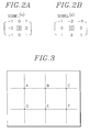
- a horizontal and a vertical sobel operators, sobel (x) and sobel (y) are exemplarily illustrated, each boxed element indicating the location of the origin.
- the horizontal and the vertical sobel operators measure the gradient of an image I(x, y) in two orthogonal directions.
- h (x) (i, j) and h (y) (i, j) are sobel coefficients at (i, j) locations of the horizontal and vertical sobel operators, respectively.
- the gradient magnitude g(x, y) is applied to an edge detection block 200 for detecting edge points on object boundaries, and the directional gradients G x (x, y) and G y (x, y) are applied to a normalization block 300 for the normalization thereof.
- the edge detection block 200 detects edge points in the video frame by comparing a gradient magnitude for each pixel in the video frame with a predetermined threshold value TH. That is, the pixel location (x, y) is an edge point if g(x, y) exceeds TH.
- the predetermined threshold value TH may be selected using the cumulative histogram of g(x, y) so that 5 to 10 % of pixels with largest gradient magnitudes are determined as edges.
- the locations of the detected edge points constitute a first edge map E(x, y), which is defined as: That is, the edge map is formed by allocating gradient magnitudes to their respective edge points and "zeros" to non-edge points.
- the edge map provides boundary information for tracing the object boundaries in the image, wherein the boundary information includes position data of the pixels in the video frame and gradient magnitudes corresponding to respective pixel positions.
- the boundary information produced by the edge detection block 200 is fed to a frame memory 500 and stored therein as the first edge map.
- the directional gradients G x (x, y) and G y (x, y) supplied from the gradient calculation block 100 are normalized as follows: wherein U x (x, y) and U y (x, y) represent the normalized horizontal and vertical gradients of the respective gradients G x (x, y) and G y (x, y) at a pixel location (x, y).
- the position data of the pixels and the normalized gradients U x (x, y) and U y (x, y) corresponding to respective pixel positions are provided to a frame memory 400 and stored therein as a second edge map.
- a grid point generation block 600 provides a plurality of grid points to an address generator 700.
- the grid points are pixel positions, e.g., A to F, located at the nodes of a grid, e.g., a rectangular grid depicted in dotted lines as shown in Fig. 3, wherein each grid point is N pixels apart from its neighboring grid points in the horizontal and vertical directions, N being an even integer.
- the address generator 700 generates, for each grid point, a set of first address data which represents locations of (N+1) x (N+1) , e.g., 9 x 9, pixels constituting a first processing block, the first processing block having the grid point at the center thereof; and generates (N+1) x (N+1) sets of second address data, each set of the second address data represents locations of (2M+1) x (2M+1) , e.g., 11 x 11, pixels (M being an odd integer) which form a second processing block, the second processing block including each of the (N+1) x (N+1) pixels included the first processing block at the center thereof.
- the set of first address data and the sets of second address data for each grid point are fed to the frame memories 500 and 400, respectively.
- first edge map data corresponding the first processing block is retrieved from the frame memory 500 and provided to a variance calculation block 800, wherein the first edge map data represents position data of the (N+1) x (N+1) pixels included in the first processing block and gradient magnitudes corresponding to respective pixel positions.
- second edge map data corresponding to each of the (N+1) x (N+1) second processing blocks is retrieved from the frame memory 400 and fed to the variance calculation block 800, wherein the second edge map data represents position data of the (2M+1) x (2M+1) pixels included in the second processing block and normalized directional gradients corresponding to those pixel positions.
- a variance of the normalized directional gradients included in each of the (N+1) x (N+1 ) second processing blocks is calculated and set to a variance for a pixel at the center thereof.
- a variance is a measure of deviation of sample values from their mean value, which implies that the greater the variance, the greater the degree of distribution of the gradients, i.e., the more complicated boundary configuration around the center pixel.
- the variance calculation block 800 provides third edge map data for each first processing block to a first selector 900, wherein the third edge map data includes pixel position data of the (N+1) x (N+1) pixels within the first processing block and gradient magnitudes and calculated variances Var(x, y) corresponding to respective pixel positions included in the first processing block.
- the first selector 900 selects maximum P, e.g., 5, pixels in the order of variance magnitudes beginning from a largest one, wherein P being a predetermined number larger than 1. Specifically, if the first processing block includes P or more pixels having non-zero valued gradient magnitudes, P pixels are selected therefrom in a descending order of their variances; if less than P pixels having non-zero valued gradient magnitudes exist, all of those pixels are selected; and if all the pixels in the first processing block have zero valued gradient magnitudes, no pixel is selected.
- P e.g. 5, pixels in the order of variance magnitudes beginning from a largest one, wherein P being a predetermined number larger than 1.
- a motion vector of a feature point is determined by using a block matching algorithm. That is, a motion vector for a search block of, e.g., 5 x 5 pixels having the feature point at the center thereof is determined by using the conventional block matching algorithm and the motion vector of the search block is assigned to a motion vector of the feature point.
- the boundary configuration around the feature point FP2 is relatively simple so that a matching point of the feature point FP2 may be assigned to a point, e.g., FP2'', FP2' or FP2''', on a similar boundary configuration. Accordingly, the motion vector for the feature point FP1 having a larger variance of gradients has more chance to reflect the real motion of the object than the feature point FP2 having a smaller variance.
- the first selector 900 provides forth edge map data to a second selector 1000, the forth edge map data including position data of the selected pixels and a gradient magnitude corresponding to each of the selected maximum P pixels.
- the second selector 1000 compares the gradient magnitudes in the forth edge map data provided from the first selector 900 and selects a pixel having a largest gradient magnitude thereby setting the pixel as a selected feature point.
- An output from the second selector 1000 is a position data of the selected feature point.
- a pixel with the greatest magnitude is selected among pixels having largest variances in the block as a feature point of the block.
- first processing block can be made to have N 1 x N 2 pixels as long as a set of first processing blocks constitute the video frame, N 1 and N 2 being positive integers.
Abstract
Description
- The present invention relates to a method and an apparatus for determining feature points; and, more particularly, to a method and an apparatus for determining feature points based on pixel intensity gradients and variances thereof.
- As is well known, transmission of digitized video signals can attain video images of a much higher quality than the transmission of analog signals. When an image signal comprising a sequence of image "frames" is expressed in a digital form, a substantial amount of data is generated for transmission, especially in the case of a high definition television system. Since, however, the available frequency bandwidth of a conventional transmission channel is limited, in order to transmit the substantial amounts of digital data therethrough, it is inevitable to compress or reduce the volume of the transmission data. Among various video compression techniques, the so-called hybrid coding technique, which combines temporal and spatial compression techniques together with a statistical coding technique, is known to be most effective.
- Most hybrid coding techniques employ a motion compensated DPCM(differential pulse coded modulation) which is a process of estimating the movement of an object between a current frame and its previous frame, and predicting the current frame according to the motion flow of the object to produce a differential signal representing the difference between the current frame and its prediction. This method is described, for example, in Staffan Ericsson, "Fixed and Adaptive Predictors for Hybrid Predictive/Transform Coding", IEEE Transactions on Communications, COM-33, No. 12 (December 1985); and in Ninomiya and Ohtsuka, "A Motion-Compensated Interframe Coding Scheme for Television Pictures", IEEE Transactions on Communications, COM-30, No. 1 (January 1982).
- In the motion compensated DPCM, current frame data is predicted from the corresponding previous frame data based on an estimation of the motion between the current and the previous frames. Such estimated motion may be described in terms of two dimensional motion vectors representing the displacement of pixels between the previous and the current frames.
- There have been two basic approaches to estimate the displacement of pixels of an object: one is a block-by-block estimation and the other is a pixel-by-pixel approach.
- In the block-by-block motion estimation, a block in a current frame is compared with blocks in its previous frame until a best match is determined. From this, an interframe displacement vector (representing how much the block of pixels has moved between frames) for the whole block can be estimated for the current frame being transmitted. However, in the block-by-block motion estimation, poor estimates may result if all pixels in the block do not move in a same way, to thereby decrease the overall picture quality.
- Using a pixel-by-pixel approach, on the other hand, a displacement is determined for each and every pixel. This technique allows a more exact estimation of the pixel value and has the ability to easily handle scale changes (e.g., zooming, movement perpendicular to the image plane). However, in the pixel-by-pixel approach, since a motion vector is determined for each and every pixel, it is virtually impossible to transmit all of the motion vectors to a receiver.
- One of the techniques introduced to ameliorate the problem of dealing with the surplus or superfluous transmission data resulting from the pixel-by-pixel approach is a feature point-based motion estimation method. In the feature point-based motion estimation technique, a set of selected pixels, i.e., feature points are determined at an encoder in a transmitting end and a decoder in a receiving end in an identical manner and motion vectors for the feature points are transmitted to the receiver without bearing position data for those feature points, wherein the feature points are defined as pixels of a previous frame or a current frame capable of representing motions of objects in a video signal so that motion vectors for all the pixels of the current frame can be recovered or approximated from those of the feature points in the receiver. In an encoder which adopts the motion estimation based on feature points, disclosed in a commonly owned copending application, U.S. Ser. No. 08/367, 520, entitled " Method and Apparatus for Encoding a Video Signal Using Pixel-by-Pixel Motion Estimation", a number of feature points are first selected from all of the pixels contained in the previous frame. Then, motion vectors for the selected feature points are determined, wherein each of the motion vectors represents a spatial displacement between one feature point in the previous frame and a corresponding matching point, i.e., a most similar pixel, in the current frame. Specifically, the matching point for each of the feature points is searched in a search region within the current frame, wherein the search region is defined as a region of a predetermined area which encompasses the position of the corresponding feature point. In the feature point-based motion estimation technique, since the current frame is predicted from the previous frame based on those motion vectors for a set of feature points, it is important to select the feature points capable of correctly representing the movement of the object.
- Typically, in an encoder and a decoder which adopt the motion estimation based on feature points, a number of feature points are selected by using a grid technique or a combination of an edge detection technique and the grid technique.
- In the grid technique employing various types of grid, e.g., a rectangular or hexagonal grid, the nodes, i.e., grid points of the grid, are determined as the feature points, and in the combination of the edge detection technique and the grid technique, intersection points of the grid and the edge of the object are selected as the feature points. However, the grid points or the intersection points do not always correctly represent the movement of the object, resulting in a poor motion estimation of the object.
- It is, therefore, a primary object of the present invention to provide an improved method and apparatus for determining feature points through the use of pixel intensity gradients and variances of those pixels on object boundaries.
- In accordance with the invention, there is provided an apparatus, for use in a video signal processor which adopts a feature point based motion compensation technique, for determining feature points, said feature points being pixels capable of representing motions of objects in a video frame, comprising: means for providing directional gradients and a gradient magnitude for each pixel in the video frame; means for normalizing the directional gradients by dividing the directional gradients with the gradient magnitude; means for generating a first edge map having the gradient magnitude for each pixel; means for generating a second edge map having the normalized directional gradients for each pixel; means for dividing the first edge map into a plurality of blocks of an identical size, wherein the blocks do not overlap each other and each of the blocks includes a gradient magnitude corresponding to each of the pixels therein; means for providing, for each of the pixels included in each of the blocks, normalized directional gradients for a set of a predetermined number of pixels from the second edge map, wherein said set of pixels includes said each of the pixels; means for obtaining a variance for each of the pixels included in each of the blocks based on the provided normalized directional gradients; and means for determining a feature point for each of the blocks based on the gradient magnitude and variance corresponding to each of the pixels therein.
- The above and other objects and features of the present invention will become apparent from the following description of preferred embodiments given in conjunction with the accompanying drawings, in which:
- Fig. 1 depicts a block diagram of the inventive apparatus for determining feature points;
- Figs. 2A and 2B show a horizonal and a vertical sobel operators;
- Fig. 3 offers exemplary grid points generated by employing a rectangular grid; and
- Fig. 4 represents a diagram explaining the feature point determination scheme employed in the present invention.
- Referring to Fig. 1, there is illustrated an apparatus, for use in an encoder and a decoder which adopt a feature point based motion compensation technique, for determining feature points in accordance with the present invention, wherein the feature points are defined as pixels capable of representing motions of objects in a video signal. A digital video signal of a video frame, e.g., a previous or a current frame, is fed to a
gradient calculation block 100. - At the
gradient calculation block 100, pixel intensity gradients for all of the pixels in the video frame are calculated by using a gradient operator, e.g., a sobel operator. The sobel operator computes horizontal and vertical differences of local sums, and has the desirable property of yielding zeros for uniform regions. In Figs. 2A and 2B, a horizontal and a vertical sobel operators, sobel(x) and sobel(y), are exemplarily illustrated, each boxed element indicating the location of the origin. The horizontal and the vertical sobel operators measure the gradient of an image I(x, y) in two orthogonal directions. Directional gradients, i.e., horizontal and vertical gradients Gx(x, y) and Gy(x, y) at a pixel location (x, y), are defined as:
- A gradient magnitude g(x, y) at the pixel location (x, y) is then given by

- The gradient magnitude g(x, y) is applied to an
edge detection block 200 for detecting edge points on object boundaries, and the directional gradients Gx(x, y) and Gy(x, y) are applied to anormalization block 300 for the normalization thereof. - The
edge detection block 200 detects edge points in the video frame by comparing a gradient magnitude for each pixel in the video frame with a predetermined threshold value TH. That is, the pixel location (x, y) is an edge point if g(x, y) exceeds TH. - Typically, the predetermined threshold value TH may be selected using the cumulative histogram of g(x, y) so that 5 to 10 % of pixels with largest gradient magnitudes are determined as edges. The locations of the detected edge points constitute a first edge map E(x, y), which is defined as:

edge detection block 200 is fed to aframe memory 500 and stored therein as the first edge map. - At the
normalization block 300, the directional gradients Gx(x, y) and Gy(x, y) supplied from thegradient calculation block 100 are normalized as follows:
frame memory 400 and stored therein as a second edge map. - In the meantime, a grid
point generation block 600 provides a plurality of grid points to anaddress generator 700. The grid points are pixel positions, e.g., A to F, located at the nodes of a grid, e.g., a rectangular grid depicted in dotted lines as shown in Fig. 3, wherein each grid point is N pixels apart from its neighboring grid points in the horizontal and vertical directions, N being an even integer. Theaddress generator 700 generates, for each grid point, a set of first address data which represents locations of


frame memories - In response to the set of first address data for each grid point from the
address generator 700, first edge map data corresponding the first processing block is retrieved from theframe memory 500 and provided to avariance calculation block 800, wherein the first edge map data represents position data of the
address generator 700, second edge map data corresponding to each of the
frame memory 400 and fed to thevariance calculation block 800, wherein the second edge map data represents position data of the
- At the
variance calculation block 800, a variance of the normalized directional gradients included in each of the
- A variance Var(x, y) at a position (x, y) may then be defined as:


-


- Thereafter, the
variance calculation block 800 provides third edge map data for each first processing block to afirst selector 900, wherein the third edge map data includes pixel position data of the
- The
first selector 900 selects maximum P, e.g., 5, pixels in the order of variance magnitudes beginning from a largest one, wherein P being a predetermined number larger than 1. Specifically, if the first processing block includes P or more pixels having non-zero valued gradient magnitudes, P pixels are selected therefrom in a descending order of their variances; if less than P pixels having non-zero valued gradient magnitudes exist, all of those pixels are selected; and if all the pixels in the first processing block have zero valued gradient magnitudes, no pixel is selected. - Referring to Fig. 4, there is illustrated a diagram explaining the feature point determination scheme employed in the present invention. Assuming a displacement of an object between two video frames is MV and two feature points FP1 and FP2 are selected on the boundary of the object. Normally, a motion vector of a feature point is determined by using a block matching algorithm. That is, a motion vector for a search block of, e.g., 5 x 5 pixels having the feature point at the center thereof is determined by using the conventional block matching algorithm and the motion vector of the search block is assigned to a motion vector of the feature point. In such a case, since the feature point FP1 is situated on a rather complicated portion of the object boundary, a matching point of the feature point FP1 can be uniquely determined at a real matching point FP1'. On the other hand, the boundary configuration around the feature point FP2 is relatively simple so that a matching point of the feature point FP2 may be assigned to a point, e.g., FP2'', FP2' or FP2''', on a similar boundary configuration. Accordingly, the motion vector for the feature point FP1 having a larger variance of gradients has more chance to reflect the real motion of the object than the feature point FP2 having a smaller variance.
- Subsequently, the
first selector 900 provides forth edge map data to asecond selector 1000, the forth edge map data including position data of the selected pixels and a gradient magnitude corresponding to each of the selected maximum P pixels. - The
second selector 1000 compares the gradient magnitudes in the forth edge map data provided from thefirst selector 900 and selects a pixel having a largest gradient magnitude thereby setting the pixel as a selected feature point. An output from thesecond selector 1000 is a position data of the selected feature point. - In accordance with the present invention, for each block which includes one or more pixels having non-zero valued gradient magnitudes, a pixel with the greatest magnitude is selected among pixels having largest variances in the block as a feature point of the block. As a result, each feature point is determined on a portion of the object boundaries having complicated configuration, which is conducive to the better estimation of motion vectors for the feature points.
- Even though the preferred embodiments of the invention have been described with reference to the first processing blocks of

- While the present invention has been shown and described with reference to the particular embodiments, it will be apparent to those skilled in the art that many changes and modifications may be made without departing from the spirit and scope of the invention as defined in the appended claims.
Claims (4)
- An apparatus, for use in a video signal processor which adopts a feature point based motion compensation technique, for determining feature points, said feature points being pixels capable of representing motions of objects in a video frame, comprising:means or providing directional gradients and a gradient magnitude for each pixel in the video frame;means for normalizing the directional gradients by dividing the directional gradients with the gradient magnitude;means for generating a first edge map having the gradient magnitude for each pixel;means for generating a second edge map having the normalized directional gradients for each pixel;means for dividing the first edge map into a plurality of blocks of an identical size, wherein the blocks do not overlap each other and each of the blocks includes a gradient magnitude corresponding to each of the pixels therein;means for providing, for each of the pixels included in each of the blocks, normalized directional gradients for a set of a predetermined number of pixels from the second edge map, wherein said set of pixels includes said each of the pixels;means for obtaining a variance for each of the pixels included in each of the blocks based on the provided normalized directional gradients; andmeans for determining a feature point for each of the blocks based on the gradient magnitude and variance corresponding to each of the pixels therein.
- The apparatus according to claim 1, wherein said determination means includes:means for selecting maximum P pixels, for each of the blocks, in the order of the variances thereof beginning from a largest one, P being a predetermined number larger than 1, such that if P or more pixels having non-zero valued gradient magnitudes are included in each of the blocks, P pixels are selected in a descending order of their variances, if fewer than P number of pixels having non-zero valued gradient magnitudes exist, all of those pixels are selected, and if all the pixels in each of the blocks have the zero-valued gradient magnitude, no pixel is selected; andmeans for determining a pixel having a largest gradient magnitude among the selected maximum pixels as the feature point for each of the blocks.
- A method, for use in a video signal processor which adopts a feature point based motion compensation technique, for determining feature points, said feature points being pixels capable of representing motions of objects in a video frame, comprising the steps of:(a) providing directional gradients and a gradient magnitude for each pixel in the video frame;(b) normalizing the directional gradients by dividing the directional gradients with the gradient magnitude;(c) generating a first edge map having the gradient magnitude for each pixel;(d) generating a second edge map having the normalized direction gradients for each pixel;(e) dividing the first edge map into a plurality of blocks of an identical size, wherein the blocks do not overlap each other and each of the blocks includes a gradient magnitude corresponding to each of the pixels therein;(f) providing, for each of the pixels included in each of the blocks, normalized directional gradients for a set of a predetermined number of pixels from the second edge map, wherein said set of pixels includes said each of the pixels;(g) obtaining a variance for each of the pixels included in each of the blocks based on the provided normalized directional gradients;(h) determining a feature point for each of the blocks based on the gradient magnitude and variance corresponding to each of the pixels therein.
- The method in accordance with claim 3, wherein said step(h) includes the steps of:(h1) selecting maximum P pixels, for each of the blocks, in the order of the variances thereof beginning from a largest one, P being a predetermined number larger than 1, such that if P or more pixels having non-zero valued gradient magnitudes are included in each of the blocks, P pixels are selected in a descending order of their variances, if fewer than P number of pixels having non-zero valued gradient magnitudes exist, all of those pixels are selected, and if all the pixels in each of the blocks have the zero-valued gradient magnitude, no pixel is selected; and(h2) determining a pixel having a largest gradient magnitude among the selected maximum pixels as the feature point for each of the blocks.
Applications Claiming Priority (2)
| Application Number | Priority Date | Filing Date | Title |
|---|---|---|---|
| KR1019950005857A KR0171147B1 (en) | 1995-03-20 | 1995-03-20 | Apparatus for selecting feature point by means of gradient |
| KR9505857 | 1995-03-20 |
Publications (3)
| Publication Number | Publication Date |
|---|---|
| EP0733996A2 true EP0733996A2 (en) | 1996-09-25 |
| EP0733996A3 EP0733996A3 (en) | 1998-07-08 |
| EP0733996B1 EP0733996B1 (en) | 2005-08-24 |
Family
ID=19410184
Family Applications (1)
| Application Number | Title | Priority Date | Filing Date |
|---|---|---|---|
| EP95106838A Expired - Lifetime EP0733996B1 (en) | 1995-03-20 | 1995-05-05 | Method and apparatus for determining feature points |
Country Status (6)
| Country | Link |
|---|---|
| US (1) | US5694487A (en) |
| EP (1) | EP0733996B1 (en) |
| JP (1) | JP3621152B2 (en) |
| KR (1) | KR0171147B1 (en) |
| CN (1) | CN1098596C (en) |
| DE (1) | DE69534399T2 (en) |
Cited By (2)
| Publication number | Priority date | Publication date | Assignee | Title |
|---|---|---|---|---|
| GB2328127B (en) * | 1997-08-05 | 2002-04-10 | Canon Kk | Image processing apparatus |
| US6647146B1 (en) | 1997-08-05 | 2003-11-11 | Canon Kabushiki Kaisha | Image processing apparatus |
Families Citing this family (47)
| Publication number | Priority date | Publication date | Assignee | Title |
|---|---|---|---|---|
| US5825929A (en) * | 1995-10-05 | 1998-10-20 | Microsoft Corporation | Transformation block optimization method |
| US6037988A (en) * | 1996-03-22 | 2000-03-14 | Microsoft Corp | Method for generating sprites for object-based coding sytems using masks and rounding average |
| US8625665B2 (en) * | 1996-09-20 | 2014-01-07 | At&T Intellectual Property Ii, L.P. | Video coder providing implicit coefficient prediction and scan adaptation for image coding and intra coding of video |
| US6408109B1 (en) * | 1996-10-07 | 2002-06-18 | Cognex Corporation | Apparatus and method for detecting and sub-pixel location of edges in a digital image |
| JP3853034B2 (en) * | 1997-08-13 | 2006-12-06 | シスメックス株式会社 | Object boundary determination method and apparatus, and recording medium recording object boundary determination program |
| US6289112B1 (en) * | 1997-08-22 | 2001-09-11 | International Business Machines Corporation | System and method for determining block direction in fingerprint images |
| US6975764B1 (en) * | 1997-11-26 | 2005-12-13 | Cognex Technology And Investment Corporation | Fast high-accuracy multi-dimensional pattern inspection |
| US6229578B1 (en) * | 1997-12-08 | 2001-05-08 | Intel Corporation | Edge-detection based noise removal algorithm |
| US6400831B2 (en) | 1998-04-02 | 2002-06-04 | Microsoft Corporation | Semantic video object segmentation and tracking |
| US6173083B1 (en) * | 1998-04-14 | 2001-01-09 | General Electric Company | Method and apparatus for analyzing image structures |
| US7016539B1 (en) * | 1998-07-13 | 2006-03-21 | Cognex Corporation | Method for fast, robust, multi-dimensional pattern recognition |
| US6711278B1 (en) | 1998-09-10 | 2004-03-23 | Microsoft Corporation | Tracking semantic objects in vector image sequences |
| US6898319B1 (en) * | 1998-09-11 | 2005-05-24 | Intel Corporation | Method and system for video frame enhancement using edge detection |
| US6314201B1 (en) * | 1998-10-16 | 2001-11-06 | Agilent Technologies, Inc. | Automatic X-ray determination of solder joint and view delta Z values from a laser mapped reference surface for circuit board inspection using X-ray laminography |
| US6697497B1 (en) | 1998-12-22 | 2004-02-24 | Novell, Inc. | Boundary identification and characterization through density differencing |
| JP4496595B2 (en) * | 1999-03-29 | 2010-07-07 | ソニー株式会社 | Image processing apparatus, image processing method, and recording medium |
| JP4344964B2 (en) * | 1999-06-01 | 2009-10-14 | ソニー株式会社 | Image processing apparatus and image processing method |
| FI110743B (en) * | 1999-06-28 | 2003-03-14 | Valtion Teknillinen | Method and system for performing motion estimation |
| KR100415266B1 (en) * | 2000-05-11 | 2004-01-16 | 가부시끼가이샤 도시바 | Object region information description method, object region information generating device and recording medium |
| US7430303B2 (en) * | 2002-03-29 | 2008-09-30 | Lockheed Martin Corporation | Target detection method and system |
| US7308136B2 (en) * | 2002-07-01 | 2007-12-11 | Xerox Corporation | Weak edge repositioning in a MRC segmentor |
| DE10239343A1 (en) * | 2002-08-28 | 2004-03-11 | Philips Intellectual Property & Standards Gmbh | Process for processing a skin impression image |
| EP1418546A1 (en) * | 2002-11-07 | 2004-05-12 | Mitsubishi Electric Information Technology Centre Europe B.V. | Method and apparatus for representing moving objects in a sequence of images |
| US8081820B2 (en) | 2003-07-22 | 2011-12-20 | Cognex Technology And Investment Corporation | Method for partitioning a pattern into optimized sub-patterns |
| US7190834B2 (en) | 2003-07-22 | 2007-03-13 | Cognex Technology And Investment Corporation | Methods for finding and characterizing a deformed pattern in an image |
| US7343048B2 (en) * | 2003-09-18 | 2008-03-11 | Arcsoft, Inc. | Edge based alignment algorithm |
| US7289147B2 (en) * | 2004-02-03 | 2007-10-30 | Hewlett-Packard Development Company, L.P. | Method for providing image alignment feedback for panorama (composite) images in digital cameras using edge detection |
| US8437502B1 (en) | 2004-09-25 | 2013-05-07 | Cognex Technology And Investment Corporation | General pose refinement and tracking tool |
| US7620241B2 (en) * | 2004-11-30 | 2009-11-17 | Hewlett-Packard Development Company, L.P. | Artifact reduction in a digital video |
| CN1797429A (en) * | 2004-12-29 | 2006-07-05 | 鸿富锦精密工业(深圳)有限公司 | System and method of 2D analytical process for image |
| JP4581733B2 (en) * | 2005-02-17 | 2010-11-17 | ソニー株式会社 | Encoding apparatus and method, decoding apparatus and method, recording medium, program, and image processing system |
| US7440608B2 (en) * | 2005-05-31 | 2008-10-21 | Hewlett-Packard Development Company, L.P. | Method and system for detecting image defects |
| US7965774B2 (en) * | 2006-01-06 | 2011-06-21 | International Business Machines Corporation | Method for visual signal extrapolation or interpolation |
| US8212717B2 (en) * | 2006-10-26 | 2012-07-03 | Raytheon Company | Radar imaging system and method using second moment spatial variance |
| US8054217B2 (en) * | 2006-10-26 | 2011-11-08 | Raytheon Company | Radar imaging system and method using gradient magnitude second moment spatial variance detection |
| WO2008081853A1 (en) * | 2006-12-28 | 2008-07-10 | Alps Electric Co., Ltd. | Image processing method |
| US8103085B1 (en) | 2007-09-25 | 2012-01-24 | Cognex Corporation | System and method for detecting flaws in objects using machine vision |
| US20100166257A1 (en) * | 2008-12-30 | 2010-07-01 | Ati Technologies Ulc | Method and apparatus for detecting semi-transparencies in video |
| JP2010193186A (en) * | 2009-02-18 | 2010-09-02 | Nikon Corp | Image editing device, imaging apparatus and image editing program |
| JP5115497B2 (en) * | 2009-02-27 | 2013-01-09 | 富士通セミコンダクター株式会社 | Image processing program, image processing apparatus, and image processing method |
| EP2481012A2 (en) | 2009-12-02 | 2012-08-01 | Tata Consultancy Services Limited | Cost-effective system and method for detecting, classifying and tracking the pedestrian using near infrared camera |
| US8553933B2 (en) | 2010-11-10 | 2013-10-08 | Raytheon Company | Edge diversity object detection |
| JP5663283B2 (en) | 2010-12-02 | 2015-02-04 | オリンパス株式会社 | Endoscopic image processing apparatus and program |
| CN103177421B (en) * | 2011-12-26 | 2017-02-15 | 深圳市蓝韵实业有限公司 | Noise reduction processing method of ultrasound medical image |
| US9679224B2 (en) | 2013-06-28 | 2017-06-13 | Cognex Corporation | Semi-supervised method for training multiple pattern recognition and registration tool models |
| US9554086B1 (en) * | 2014-01-03 | 2017-01-24 | Pixelworks, Inc. | True motion vector editing tool |
| CN110692242B (en) * | 2017-06-05 | 2023-10-03 | 松下电器(美国)知识产权公司 | Encoding device, decoding device, encoding method, and decoding method |
Citations (4)
| Publication number | Priority date | Publication date | Assignee | Title |
|---|---|---|---|---|
| US4499598A (en) * | 1982-07-02 | 1985-02-12 | Conoco Inc. | Edge and line detection in multidimensional noisey, imagery data |
| US4838685A (en) * | 1987-04-03 | 1989-06-13 | Massachusetts Institute Of Technology | Methods and apparatus for motion estimation in motion picture processing |
| US4910786A (en) * | 1985-09-30 | 1990-03-20 | Eichel Paul H | Method of detecting intensity edge paths |
| US5144688A (en) * | 1990-03-23 | 1992-09-01 | Board Of Regents, The University Of Texas System | Method and apparatus for visual pattern image coding |
Family Cites Families (2)
| Publication number | Priority date | Publication date | Assignee | Title |
|---|---|---|---|---|
| JPS5626626B2 (en) * | 1973-09-19 | 1981-06-19 | ||
| JPS62172867A (en) * | 1986-01-25 | 1987-07-29 | Minolta Camera Co Ltd | Picture processor |
-
1995
- 1995-03-20 KR KR1019950005857A patent/KR0171147B1/en not_active IP Right Cessation
- 1995-05-04 US US08/434,824 patent/US5694487A/en not_active Expired - Lifetime
- 1995-05-05 DE DE1995634399 patent/DE69534399T2/en not_active Expired - Lifetime
- 1995-05-05 EP EP95106838A patent/EP0733996B1/en not_active Expired - Lifetime
- 1995-05-12 CN CN95105460A patent/CN1098596C/en not_active Expired - Lifetime
- 1995-05-15 JP JP13990695A patent/JP3621152B2/en not_active Expired - Lifetime
Patent Citations (4)
| Publication number | Priority date | Publication date | Assignee | Title |
|---|---|---|---|---|
| US4499598A (en) * | 1982-07-02 | 1985-02-12 | Conoco Inc. | Edge and line detection in multidimensional noisey, imagery data |
| US4910786A (en) * | 1985-09-30 | 1990-03-20 | Eichel Paul H | Method of detecting intensity edge paths |
| US4838685A (en) * | 1987-04-03 | 1989-06-13 | Massachusetts Institute Of Technology | Methods and apparatus for motion estimation in motion picture processing |
| US5144688A (en) * | 1990-03-23 | 1992-09-01 | Board Of Regents, The University Of Texas System | Method and apparatus for visual pattern image coding |
Non-Patent Citations (2)
| Title |
|---|
| KOTTKE D P ET AL: "MOTION ESTIMATION VIA CLUSTER MATCHING" IEEE TRANSACTIONS ON PATTERN ANALYSIS AND MACHINE INTELLIGENCE, vol. 16, no. 11, 1 November 1994, pages 1128-1132, XP000481001 * |
| ZAKHOR A ET AL: "EDGE-BASED 3-D CAMERA MOTION ESTIMATION WITH APPLICATION TO VIDEO CODING" IEEE TRANSACTIONS ON IMAGE PROCESSING, vol. 2, no. 4, 1 October 1993, pages 481-498, XP000412063 * |
Cited By (2)
| Publication number | Priority date | Publication date | Assignee | Title |
|---|---|---|---|---|
| GB2328127B (en) * | 1997-08-05 | 2002-04-10 | Canon Kk | Image processing apparatus |
| US6647146B1 (en) | 1997-08-05 | 2003-11-11 | Canon Kabushiki Kaisha | Image processing apparatus |
Also Published As
| Publication number | Publication date |
|---|---|
| DE69534399D1 (en) | 2005-09-29 |
| JPH08265745A (en) | 1996-10-11 |
| CN1098596C (en) | 2003-01-08 |
| KR0171147B1 (en) | 1999-03-20 |
| EP0733996A3 (en) | 1998-07-08 |
| JP3621152B2 (en) | 2005-02-16 |
| CN1134077A (en) | 1996-10-23 |
| KR960036703A (en) | 1996-10-28 |
| EP0733996B1 (en) | 2005-08-24 |
| US5694487A (en) | 1997-12-02 |
| DE69534399T2 (en) | 2006-03-16 |
Similar Documents
| Publication | Publication Date | Title |
|---|---|---|
| EP0733996B1 (en) | Method and apparatus for determining feature points | |
| KR0171146B1 (en) | Feature point based motion vectors detecting apparatus | |
| US5612743A (en) | Method for encoding a video signal using feature point based motion estimation | |
| US5546129A (en) | Method for encoding a video signal using feature point based motion estimation | |
| US5598216A (en) | Method and apparatus for encoding/decoding a video signal | |
| US5760846A (en) | Apparatus for estimating motion vectors for feature points of a video signal | |
| US5673339A (en) | Method for encoding a video signal using feature point based motion estimation | |
| EP0721287A1 (en) | Method and apparatus for encoding a video signal | |
| US5686973A (en) | Method for detecting motion vectors for use in a segmentation-based coding system | |
| US5727078A (en) | Process for estimating disparity between the monoscopic images making up a sterescopic image | |
| US5619281A (en) | Method and apparatus for detecting motion vectors in a frame decimating video encoder | |
| US6625216B1 (en) | Motion estimation using orthogonal transform-domain block matching | |
| EP0734165A2 (en) | Image processing system using pixel-by-pixel motion estimation and frame decimation | |
| EP0625853A2 (en) | Moving image encoder and decoder | |
| EP0737012A2 (en) | Method for segmenting and estimating a moving object motion | |
| US5638129A (en) | Image processing apparatus using a pixel-by-pixel motion estimation based on feature points | |
| US5627591A (en) | Image processing system using a pixel-by-pixel motion estimation based on feature points | |
| EP0721284A1 (en) | An image processing system using pixel-by-pixel motion estimation and frame decimation | |
| US5731851A (en) | Method for determining feature points based on hierarchical block searching technique | |
| US6020925A (en) | Method and apparatus for encoding a video signal using pixel-by-pixel motion prediction | |
| US5625417A (en) | Image processing system using a feature point-based motion estimation | |
| KR0174455B1 (en) | Method and apparatus for encoding a video signal using pixel-by-pixel motion prediction | |
| EP0720381A1 (en) | Method and apparatus for encoding a video signal using pixel-by-pixel motion prediction | |
| KR0178228B1 (en) | Enhanced movingvector estimation method and apparatus for image signal decoding system | |
| JPH08205176A (en) | Apparatus and method for video signal coding |
Legal Events
| Date | Code | Title | Description |
|---|---|---|---|
| PUAI | Public reference made under article 153(3) epc to a published international application that has entered the european phase |
Free format text: ORIGINAL CODE: 0009012 |
|
| AK | Designated contracting states |
Kind code of ref document: A2 Designated state(s): DE FR GB NL |
|
| PUAL | Search report despatched |
Free format text: ORIGINAL CODE: 0009013 |
|
| AK | Designated contracting states |
Kind code of ref document: A3 Designated state(s): DE FR GB NL |
|
| 17P | Request for examination filed |
Effective date: 19981201 |
|
| 17Q | First examination report despatched |
Effective date: 20000406 |
|
| RAP1 | Party data changed (applicant data changed or rights of an application transferred) |
Owner name: DAEWOO ELECTRONICS CORPORATION |
|
| GRAP | Despatch of communication of intention to grant a patent |
Free format text: ORIGINAL CODE: EPIDOSNIGR1 |
|
| GRAS | Grant fee paid |
Free format text: ORIGINAL CODE: EPIDOSNIGR3 |
|
| GRAA | (expected) grant |
Free format text: ORIGINAL CODE: 0009210 |
|
| AK | Designated contracting states |
Kind code of ref document: B1 Designated state(s): DE FR GB NL |
|
| REG | Reference to a national code |
Ref country code: GB Ref legal event code: FG4D |
|
| REF | Corresponds to: |
Ref document number: 69534399 Country of ref document: DE Date of ref document: 20050929 Kind code of ref document: P |
|
| ET | Fr: translation filed | ||
| PLBE | No opposition filed within time limit |
Free format text: ORIGINAL CODE: 0009261 |
|
| STAA | Information on the status of an ep patent application or granted ep patent |
Free format text: STATUS: NO OPPOSITION FILED WITHIN TIME LIMIT |
|
| 26N | No opposition filed |
Effective date: 20060526 |
|
| REG | Reference to a national code |
Ref country code: DE Ref legal event code: R082 Ref document number: 69534399 Country of ref document: DE Representative=s name: SAMSON & PARTNER, PATENTANWAELTE, DE |
|
| REG | Reference to a national code |
Ref country code: GB Ref legal event code: 732E Free format text: REGISTERED BETWEEN 20130404 AND 20130410 |
|
| REG | Reference to a national code |
Ref country code: DE Ref legal event code: R082 Ref document number: 69534399 Country of ref document: DE Representative=s name: SAMSON & PARTNER PATENTANWAELTE MBB, DE Effective date: 20130313 Ref country code: DE Ref legal event code: R082 Ref document number: 69534399 Country of ref document: DE Representative=s name: SAMSON & PARTNER, PATENTANWAELTE, DE Effective date: 20130313 Ref country code: DE Ref legal event code: R081 Ref document number: 69534399 Country of ref document: DE Owner name: MAPLE VISION TECHNOLOGIES INC., CA Free format text: FORMER OWNER: DAEWOO ELECTRONICS CORP., SEOUL/SOUL, KR Effective date: 20130313 |
|
| REG | Reference to a national code |
Ref country code: FR Ref legal event code: TP Owner name: MAPLE VISION TECHNOLOGIES INC., CA Effective date: 20131226 |
|
| PGFP | Annual fee paid to national office [announced via postgrant information from national office to epo] |
Ref country code: GB Payment date: 20140430 Year of fee payment: 20 |
|
| PGFP | Annual fee paid to national office [announced via postgrant information from national office to epo] |
Ref country code: FR Payment date: 20140509 Year of fee payment: 20 Ref country code: DE Payment date: 20140430 Year of fee payment: 20 Ref country code: NL Payment date: 20140510 Year of fee payment: 20 |
|
| REG | Reference to a national code |
Ref country code: NL Ref legal event code: V4 Effective date: 20150505 Ref country code: DE Ref legal event code: R071 Ref document number: 69534399 Country of ref document: DE |
|
| REG | Reference to a national code |
Ref country code: GB Ref legal event code: PE20 Expiry date: 20150504 |
|
| PG25 | Lapsed in a contracting state [announced via postgrant information from national office to epo] |
Ref country code: GB Free format text: LAPSE BECAUSE OF EXPIRATION OF PROTECTION Effective date: 20150504 |