EP0726745B1 - Electrolytically severable joint for endovascular embolic devices - Google Patents
Electrolytically severable joint for endovascular embolic devices Download PDFInfo
- Publication number
- EP0726745B1 EP0726745B1 EP95900494A EP95900494A EP0726745B1 EP 0726745 B1 EP0726745 B1 EP 0726745B1 EP 95900494 A EP95900494 A EP 95900494A EP 95900494 A EP95900494 A EP 95900494A EP 0726745 B1 EP0726745 B1 EP 0726745B1
- Authority
- EP
- European Patent Office
- Prior art keywords
- guidewire
- core wire
- link
- coil
- disintegration
- Prior art date
- Legal status (The legal status is an assumption and is not a legal conclusion. Google has not performed a legal analysis and makes no representation as to the accuracy of the status listed.)
- Expired - Lifetime
Links
Images


Classifications
-
- A—HUMAN NECESSITIES
- A61—MEDICAL OR VETERINARY SCIENCE; HYGIENE
- A61B—DIAGNOSIS; SURGERY; IDENTIFICATION
- A61B17/00—Surgical instruments, devices or methods, e.g. tourniquets
- A61B17/12—Surgical instruments, devices or methods, e.g. tourniquets for ligaturing or otherwise compressing tubular parts of the body, e.g. blood vessels, umbilical cord
- A61B17/12022—Occluding by internal devices, e.g. balloons or releasable wires
- A61B17/12099—Occluding by internal devices, e.g. balloons or releasable wires characterised by the location of the occluder
- A61B17/12109—Occluding by internal devices, e.g. balloons or releasable wires characterised by the location of the occluder in a blood vessel
- A61B17/12113—Occluding by internal devices, e.g. balloons or releasable wires characterised by the location of the occluder in a blood vessel within an aneurysm
-
- A—HUMAN NECESSITIES
- A61—MEDICAL OR VETERINARY SCIENCE; HYGIENE
- A61B—DIAGNOSIS; SURGERY; IDENTIFICATION
- A61B17/00—Surgical instruments, devices or methods, e.g. tourniquets
- A61B17/12—Surgical instruments, devices or methods, e.g. tourniquets for ligaturing or otherwise compressing tubular parts of the body, e.g. blood vessels, umbilical cord
- A61B17/12022—Occluding by internal devices, e.g. balloons or releasable wires
- A61B17/12131—Occluding by internal devices, e.g. balloons or releasable wires characterised by the type of occluding device
- A61B17/1214—Coils or wires
- A61B17/12145—Coils or wires having a pre-set deployed three-dimensional shape
-
- A—HUMAN NECESSITIES
- A61—MEDICAL OR VETERINARY SCIENCE; HYGIENE
- A61B—DIAGNOSIS; SURGERY; IDENTIFICATION
- A61B17/00—Surgical instruments, devices or methods, e.g. tourniquets
- A61B2017/00004—(bio)absorbable, (bio)resorbable, resorptive
-
- A—HUMAN NECESSITIES
- A61—MEDICAL OR VETERINARY SCIENCE; HYGIENE
- A61B—DIAGNOSIS; SURGERY; IDENTIFICATION
- A61B17/00—Surgical instruments, devices or methods, e.g. tourniquets
- A61B17/12—Surgical instruments, devices or methods, e.g. tourniquets for ligaturing or otherwise compressing tubular parts of the body, e.g. blood vessels, umbilical cord
- A61B17/12022—Occluding by internal devices, e.g. balloons or releasable wires
- A61B2017/1205—Introduction devices
- A61B2017/12054—Details concerning the detachment of the occluding device from the introduction device
- A61B2017/12063—Details concerning the detachment of the occluding device from the introduction device electrolytically detachable
Definitions
- This invention is an apparatus for endovascular occlusion through the formation of thrombi in arteries, veins, aneurysms, vascular malformations, and arteriovenous fistulas.
- it deals with a sacrificial link between an endovascular device which is introduced to and is intended to remain at the desired thrombus formation site and the device used to introduce the device.
- the method comprises a step of clipping the neck of the aneurysm, performing a suture ligation of the neck, or wrapping the entire aneurysm.
- Each of these procedures is formed by intrusive invasion into the body and performed from the outside of the aneurysm or target site.
- General anesthesia, craniotomy, brain retraction, and placement of a clip around the neck of the aneurysm are typically required in these surgical procedures.
- the surgical procedure is often delayed while waiting for the patient to stabilize medically. For this reason, many patients die from the underlying disease or defect prior to the initiation of the procedure.
- the wall of the aneurysm is then perforated from the outside and various techniques are used to occlude the interior in order to prevent it from rebleeding.
- the techniques used to occlude the aneurysm include electrothrombosis, adhesive embolization, hog hair embolization, and ferromagnetic thrombosis. These procedures are discussed in US-A-5,122,136 (Guglielmi et al.).
- a still further approach is the least invasive and is additionally described in Guglielmi et al. It is the endovascular approach.
- the interior of the aneurysm is entered by use of a catheter such as those shown in US-A-4,884,579 (Engelson) and also in US-A-4,739,768 (Engelson).
- These patents describe devices utilizing guidewires and catheters which allow access to the aneurysm from remote portions of the body.
- embolic devices which may be delivered through the catheter are an alternative to the extravascular and extra-intravascular approaches.
- the endovascular approach typically includes two major sections.
- the first section involves the introduction of the catheter to the aneurysm site using devices such as shown in the Engelson patents.
- the second section often involves filling the aneurysm in some fashion or another.
- a balloon may be introduced into the aneurysm from the distal portion of the catheter where it is inflated, detached, and left to occlude the aneurysm. In this way, the parent artery is preserved. Balloons are becoming less in favor because of the difficulty in introducing the balloon into the aneurysm sac, the possibility of an aneurysm rupture due to overinflation of the balloon within the aneurysm, and the risk associated with the traction produced when detaching the balloon.
- a highly desirable embolism-forming device which may be introduced into an aneurysm using endovascular placement procedures, is found in US-A-4,994,069 (Ritchart et al).
- a device typically a platinum/tungsten alloy coil having a very small diameter -- which may be introduced into an aneurysm through a catheter such as those described in Engelson above.
- These coils are often made of wire having a diameter of 0.05-0.15 mm (2-6 mils).
- the coil diameter may be 0.25-0.76 mm (10-30 mils).
- These soft, flexible coils may be of any length desirable and appropriate for the site to be occluded. For instance, the coils may be used to fill a berry aneurysm.
- a thrombus forms in the aneurysm and is shortly thereafter complemented with a collagenous material which significantly lessens the potential for aneurysm rupture.
- Coils such as seen in Ritchart et al. may be delivered to the vasculature site in a variety of ways including, e.g., mechanically detaching them from the delivery device as is shown in US-A-5,250,071 (Palermo) or by electrolytic detachment as is shown in Guglielmi et al. (US-A-5,122,136) as was discussed above.
- Guglielmi et al. shows an embolism-forming device and procedure for using that device. Specifically, Guglielmi et al. fills a vascular cavity such as an aneurysm with an embolic device such as a platinum coil which coil has been endovascularly delivered. The coil is then severed from its insertion tool by the application of a small electric current. Desirably, the insertion device involves a guidewire which is attached at its distal end to an embolic device by an electrolytic, sacrificial joint. Guglielmi et al. suggests that when the embolic device is a platinum coil, the platinum coil may be 1-50 cm. or longer as is necessary.
- Proximal of the embolic coil is a guidewire, often stainless steel in construction.
- the guidewire is used to push the platinum embolic coil, obviously with great gentleness, into the vascular site to be occluded.
- the patent shows a variety of ways to link the embolic coil to the pusher guidewire.
- the guidewire is tapered at its distal end and the distal tip of the guidewire is soldered into the proximal end of the embolic coil.
- a stainless steel coil is wrapped coaxially about the distal tapered portion of the guidewire to provide column strength to the guidewire.
- This coaxial stainless steel wire is joined both to the guidewire and to the embolic coil. Insulation may be used to cover a portion of the strength-providing stainless steel coil. This arrangement provides for two regions which must be electrolytically severed before the embolic coil is severed from the guidewire.
- a further variation of the Guglielmi detachable coil is one in which the distal tip of the stainless steel guidewire is not soldered to the proximal end of the embolic device.
- a simple conical stainless steel wire is included from the stainless steel guidewire to the embolic coil.
- Guglelmi et al. includes a thin, threadlike extension between the guidewire core and the proximal end of the embolic coil. In this way, the guidewire does not extend to the embolic coil, but instead relies upon a separately introduced extension.
- WO-A-94/10936 which was published after the priority date of the present invention and can thus at most be admissible as prior art under Article 54(3) EPC, discloses a guidewire in which an elongate tip portion may be severed by electrolytically disintegrating a severable link connecting the tip portion to a core wire.
- the tip portion is attached to the core wire at "one or more soldered joints axially spaced apart.”
- the elongate tip portion is soldered to one or both ends of a fine wire at the distal tip of the core wire.
- the soldered joints or some section of the guidewire is electrolytically decomposed.
- WO-A-93/16650 discloses an embodiment of a guidewire ( Figure 6) in which an electrolysing current may be concentrated on a sacrificial stainless steel portion of a detachable tip by disposing an insulating coating on the remaining platinum portion.
- This concentration of the electrolysing current is referred to as having the effect of decreasing the time required to electrolytically sufficiently disintegrate the steel portion to allow detachment of the platinum tip, which is an advantageous feature where a large aneurism must be treated and a multiple number of coils must be deployed within the aneurysm.
- a guidewire for use in combination with a catheter in the formation of a vascular occlusion comprising:
- the guidewire has a distal tip which may be introduced into a selected vascular site or cavity.
- the guidewire is joined to the distal tip or embolic device in such a way that the vascular device may be electrolytically detached by application of a current to the core or guidewire.
- the improvement involves the use of a discrete, sacrificial link between the core wire and the vascular device to allow clean and quick detachment from the guidewire.
- the focussed electrolysis found at the sacrificial site reduces the overall possibility of occurrence of multiple electrolysis sites and liberation of large particles from those sites.
- Figures 1, 2, 3, 5, and 6 show side view, partial cross-sectional views of variations of the inventive, electrolytically susceptible, sacrificial link between a core wire and an embolic device.
- Figure 4 shows a cross section of the variation shown in Figure 3.
- Figure 7 shows a close up side view of a variation such as found in Figure 6.
- Figure 8 shows side view of a typical assembly involving the inventive sacrificial link used in this invention.
- Figures 9 and 10 schematically depict the method for deploying the vasoocclusive device using the inventive sacrificial link.
- the assembly 100 is made up generally of a guide or core wire 102 which tapers at its distal end to a point and is soldered into the proximal end of a vasoocclusive device 104 , which in this case is a coil. All of the core wire 102 is covered with an insulating material such as Teflon®, polyurethane, polyethylene, polypropylene, or other suitable polymeric material, except the most distal exposed joint or Sacrificial link 106 . Link 106 is not coated with an electrical insulator and is of a material which is susceptible to electrolytic dissolution in blood.
- the core wire 102 is typically stainless Steel and may be disposed within a protective catheter not shown. Stainless steel guidewire 102 typically is approximately 0.25-0.76 mm (10-30 mils) in diameter. Often the guidewire is 50-300 cm. in length, that is to say, from the entry site outside the body to sacrificial link 106 .
- Sacrificial link 106 is a discrete link.
- discrete we mean to say preferably that the joint is substantially dissolved upon release of the vasoocclusive device 104 .
- Discrete further means that the length of the link 106 is no greater than the diameter of the sacrificial link 106 and that the electrolytic surface present after the vasoocclusive device is released is not substantially greater than would be a circle having the diameter of the sacrificial link 106 .
- a coil 108 which is Soldered at its proximal end and, typically, is designed to provide some column strength to the guidewire assembly while not detrimentally affecting the flexibility of the tapered portion of the core wire 102 .
- the coating on 102 is not present so to allow the solder to adhere to metal surfaces.
- a pair of insulators: sleeve 110 and end plug 112 which serve to further remove the stainless steel coil 108 from contact with the blood while the Step of electrolytic detachment is carried out.
- the end plug 112 and sleeve 110 are adhesively attached to each other so to form an electrically insulating or electrolysis-tight housing about coil 108 .
- the end plug 112 and sleeve 110 form a planar surface in the Figure which is generally planar and perpendicular to the axis of the core wire 102 .
- the distal end of guidewire or core wire 102 is inserted into the solder joint 114 forming the proximal end of vasoocclusive device 104 .
- the discrete sacrificial link 106 is completely or substantially completely dissolved during electrolysis.
- Figure 2 shows a most preferred variation of the Figure 1 device having a guide or core wire 102 which may taper at its distal end to a point and which is soldered into the proximal end of a vasoocclusive device 104 , which in this case is a coil.
- a vasoocclusive device 104 which in this case is a coil.
- the distal portion of the guidewire 102 having stainless steel coil 108 thereabout is all enclosed in an end plug 107 and sleeve 109 to provide additional protection to the guidewire and included stainless steel coil 108 .
- the major difference between the Figure 1 device and the link assembly shown in Figure 2 is the use of a bias formed distal region.
- the combination of end plug 107 and sleeve 109 allow clear access by blood (and therefore electrolytic current) to the sacrificial link (106).
- the end plug 112 and sleeve 110 form a planar surface in the Figure which is generally planar but not perpendicular to the axi
- the shape of the surface is, in and of itself, of much criticality except to the extent it allows reasonably free access of the blood to the sacrificial joint 106 .
- Curved, slotted, and other variations of the end surface are also contemplated in this invention.
- Figure 3 shows a variation of the device shown in Figures 1 or 2 in that the core wire 102 comes down to a point having a sacrificial link 106 which is soldered into solder joint 114 in vasoocclusive device 104 .
- the coil 108 provided to give additional column strength to the core wire 102 is also present.
- End plug 112 is also found in this device.
- the variation is in the outer sleeve 116 . In this variation, the outer sleeve extends up to and is in contact with the solder joint 114 found at the end of vasoocclusive device 104 .
- a sleeve 116 has a number of openings therein to allow contact of the blood with the sacrificial link 106 .
- the openings 118 may be seen both in Figure 3 and in a cross-Section found in Figure 4.
- the end plug 112 and the cross-section of the sacrificial link 106 may also be seen in Figure 4.
- the variation shown in Figure 3 may have slightly more physical strength but because of the smaller area through openings 118 , the step of electrolysis may be slightly slower.
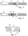
- Figure 5 shows another variation of the inventive sacrificial joint.
- the device again has a guidewire or core wire 120 which tapers down to a small point which is soldered into solder joint 114 on the end of vasoocclusive device 104 .
- all except the most distal portion 122 of core wire 120 is coated with an insulating material such as Teflon® polymer or other suitable insulating polymers.
- the sacrificial link 122 forming the distal end of core wire 120 is surrounded, as is a portion of the taper on guidewire 120 with a release spring 124 .
- Release spring 124 is attached to the guidewire body 120 but is not attached to the solder joint 114 on vasoocclusive device 104 .
- the release spring 124 is slightly compressed. It, however, has some space between its adjacent windings as it is found in place on the core wire 120 . In this way, blood has access to Sacrificial link 122 between the adjacent windings on release spring 124 .
- release spring 124 gently pushes vasoocclusive device 104 away from the tip of the guidewire or core wire 120 .
- Release spring 124 is completely insulated except, obviously, for the portion which is connected to the core wire 120 , if welding or soldering of release spring 124 is had to core wire 120 .
- Figure 6 shows a variation of the inventive device in which core wire 126 tapers down and is either directly soldered to the interior of coil 128 at solder joint 130 or is connected to a link which is then soldered at joint 130 .
- a Support spring 132 interior to coil 128 may be used in the same way as was shown in Figures 1, 2, and 3. As a safety factor, coil 128 and support spring 132 are fixed to core wire 126 . The coil 128 is also electrically connected to core wire 126 . All of core wire 126 , coil 128 , and support spring 132 are insulated so as to prevent electrolysis upon application of voltage to core wire 126 . The exception to this insulation is a scribe or score mark 134 which forms the discrete Sacrificial link.
- Score mark 134 is shown in more detail on Figure 7. Again, the effect of the scribe or score mark 134 as shown in Figure 6 is that the electrolysis takes place only at that small area and when the electrolysis has completely severed coil 128 at that point, there is little potential for electrolysis to take place at any other site on the core wire 126 or spring 128 .
- Vasoocclusive device 104 is shown in each of the drawings above to be a coil. It may be a coil or a braid or other vasoocclusive device as is already known. The vasoocclusive device may be covered or connected with fibrous materials tied to the outside of the coil or braided onto the outer cover of the coil as desired. Such fibrous adjuvants may be found in US-A-5 382 259 or in US-A-5 226 911.
- FIG 8 shows a typical layout involving the inventive discrete sacrificial joint 106 as was generally shown in the Figures above.
- a somewhat conventional Teflon® laminated or similarly insulated stainless steel guidewire assembly 140 may be placed within a protective catheter.
- stainless steel guidewire 140 may have a diameter of approximately 0.25-0.76 mm (10-30 mils).
- guidewire assembly 140 is tapered at its distal end to form a conical section 142 which joins a further section 144 which extends along a length of guidewire 146 . Section 144 then gradually narrows down to a thinner section 148 .
- the guidewire assembly 140 as noted above, may be placed within a catheter body and is typically 50-200 cm.
- the distal section of guidewire assembly 140 has an outer Teflon® sleeve 150 (or sleeve of other appropriate insulating material). Furthermore, it has an end plug 152 to permit isolation of the guidewire electrically from the blood except at sacrificial discrete link 106 .
- the proximal end of vasoocclusive device 104 is typically a soldered tip or a joint 114 .
- vasoocclusive device 104 when a coil, forms a secondary loop after it emanates from the end of the catheter.
- the distal end of vasoocclusive device 104 may also have an end plug or tip to prevent punctures of the aneurysm when introduced into the aneurysm sac.
- the coil or vasoocclusive device 104 may be pre-biased to form a cylinder or conical envelope.
- the vasoocclusive device 104 is extremely soft and its overall shape is easily deformed.
- the vasoocclusive device 104 is easily straightened so to lie axially within the catheter.
- vasoocclusive device 104 may form a shape shown in Figure 8 or may be loosely deformed to conform to the interior shape of the aneurysm.
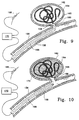
- Figure 9 shows the placement of the inventive devices shown above within a vessel 156 with the tip of catheter 158 placed near neck 160 of aneurysm 162 .
- Vasoocclusive device 164 is fed into aneurysm 162 at least until sacrificial link 106 is exposed beyond the distal tip of the catheter 158 .
- a positive electric current of approximately 0.01-2 milli-amps at 0.1-6 volts is applied to guidewire 166 to form a thrombus within aneurysm 162 .
- the negative pole 168 of power supply 170 is typically placed in electrical contact with the skin.
- vasoocclusive device 164 is detached from guidewire 166 by electrolytic disintegration of sacrificial link 106 .
- the process is typically practiced under fluoroscopic control with local anesthesia.
- a transfemoral catheter is utilized to treat a cerebral aneurysm and is usually introduced at the groin.
- the vasoocclusive device 164 is platinum, it is not effected by electrolysis.
- the guidewire and pertinent portions of the supporting coils at the distal tip of the guidewire are adequately coated with insulating coverings, only the exposed portion at the sacrificial link 106 is effected by the electrolysis.
- the shape of the tip or distal platinum coil used in combination with the guidewire according to the invention may be provided with a variety of shapes and envelopes.
Abstract
Description
wherein said single link prior to its disintegration has a length no greater than the diameter of the link and is arranged so that after its disintegration it has an electrolytic surface that is not substantially greater than would be a circle having the diameter of said single link.
Claims (13)
- A guidewire for use in combination with a catheter in the formation of a vascular occlusion, the guidewire comprising:a core wire (102,120,126), said core wire having an axis and not being susceptible to electrolytic disintegration in blood;a single, discrete, sacrificial, severable link (106,122,134) having a diameter, susceptible to electrolytic disintegration in blood and provided at the distal end of said core wire (102,120,126); andan elongate tip portion (104) connected to said core wire (102,120,126) via said single link, extending distally beyond said core wire (102,120,126) and adapted to form said occlusion at a selected site within a mammal vasculature, said elongate tip portion (104) not being susceptible to electrolytic disintegration in blood and being severable from said core wire (102,120,126) upon electrolytic disintegration of said single link (106,122,134);
wherein said single link (106,122,134) prior to its disintegration has a length no greater than the diameter of the link and is arranged so that after its disintegration it has an electrolytic surface that is not substantially greater than would be a circle having the diameter of said single link. - The guidewire of claim 1, wherein the core wire (102,120,126) is insulated (109,110,116) with a polymer proximally to said link (106,122,134).
- The guidewire of claim 2, wherein the polymer is selected from a polyflurocarbon, polyethylene, polypropylene, polyurethane, and silicone polymers.
- The guidewire of claim 2 or claim 3, wherein the polymeric insulation is a sleeve (109,110,116).
- The guidewire of any one of claims 2 to 4, wherein the insulation is coated directly onto the core wire.
- The guidewire of claim 2 wherein the core wire, proximally of said link, is insulated using a sleeve coaxial to the core wire and having an open distal end, which sleeve distal end is closed with a plug adjacent said link and coaxial to the core wire.
- The guidewire of claim 6, wherein the distal end of the sleeve and plug adjacent said link define a planar surface.
- The guidewire of claim 7, where the planar surface is generally perpendicular to the axis of the core wire.
- The guidewire of claim 7, where the planar surface is not generally perpendicular to the axis of the core wire.
- The guidewire of any one of claims 1 to 5, wherein the core wire (102) is electrically connected to a coil (108,128) located coaxially about the axis of the core wire and which is electrically insulated from surrounding blood.
- The guidewire of claim 10, wherein said link (134) is a section of the coaxial coil (128) having a score in the insulation on the coaxial coil.
- The guidewire of any one of the preceding claims, wherein the elongate portion is a coil (104).
- The guidewire of claim 12, wherein the elongate tip portion comprises a platinum alloy coil (104).
Priority Applications (1)
| Application Number | Priority Date | Filing Date | Title |
|---|---|---|---|
| EP97112221A EP0807410B1 (en) | 1993-11-03 | 1994-11-01 | Electrolytically severable joint for endovascular embolic devices |
Applications Claiming Priority (3)
| Application Number | Priority Date | Filing Date | Title |
|---|---|---|---|
| US08/147,529 US5423829A (en) | 1993-11-03 | 1993-11-03 | Electrolytically severable joint for endovascular embolic devices |
| US147529 | 1993-11-03 | ||
| PCT/US1994/012527 WO1995012367A1 (en) | 1993-11-03 | 1994-11-01 | Electrolytically severable joint for endovascular embolic devices |
Related Child Applications (1)
| Application Number | Title | Priority Date | Filing Date |
|---|---|---|---|
| EP97112221A Division EP0807410B1 (en) | 1993-11-03 | 1994-11-01 | Electrolytically severable joint for endovascular embolic devices |
Publications (3)
| Publication Number | Publication Date |
|---|---|
| EP0726745A4 EP0726745A4 (en) | 1996-06-24 |
| EP0726745A1 EP0726745A1 (en) | 1996-08-21 |
| EP0726745B1 true EP0726745B1 (en) | 1998-01-21 |
Family
ID=22521938
Family Applications (2)
| Application Number | Title | Priority Date | Filing Date |
|---|---|---|---|
| EP95900494A Expired - Lifetime EP0726745B1 (en) | 1993-11-03 | 1994-11-01 | Electrolytically severable joint for endovascular embolic devices |
| EP97112221A Expired - Lifetime EP0807410B1 (en) | 1993-11-03 | 1994-11-01 | Electrolytically severable joint for endovascular embolic devices |
Family Applications After (1)
| Application Number | Title | Priority Date | Filing Date |
|---|---|---|---|
| EP97112221A Expired - Lifetime EP0807410B1 (en) | 1993-11-03 | 1994-11-01 | Electrolytically severable joint for endovascular embolic devices |
Country Status (14)
| Country | Link |
|---|---|
| US (1) | US5423829A (en) |
| EP (2) | EP0726745B1 (en) |
| JP (1) | JP2610412B2 (en) |
| KR (1) | KR960705511A (en) |
| AT (2) | ATE162384T1 (en) |
| AU (1) | AU675892B2 (en) |
| CA (1) | CA2151924C (en) |
| DE (2) | DE69408155T2 (en) |
| DK (1) | DK0726745T3 (en) |
| ES (2) | ES2196218T3 (en) |
| IL (1) | IL111485A0 (en) |
| NO (1) | NO961756L (en) |
| TW (1) | TW273505B (en) |
| WO (1) | WO1995012367A1 (en) |
Cited By (4)
| Publication number | Priority date | Publication date | Assignee | Title |
|---|---|---|---|---|
| DE10257219B3 (en) * | 2002-12-07 | 2004-06-03 | Frank Dr. Czerwinski | Implantation of occlusion elements comprises transition section with distal end fixed to endovascular guide, and transition enclosed by helical compression spring, and nominal fracture point |
| US9161766B2 (en) | 2008-02-22 | 2015-10-20 | Covidien Lp | Methods and apparatus for flow restoration |
| US9254134B2 (en) | 2004-01-21 | 2016-02-09 | Dendron Gmbh | Device for implanting electrically isolated occlusion helixes |
| US9326774B2 (en) | 2012-08-03 | 2016-05-03 | Covidien Lp | Device for implantation of medical devices |
Families Citing this family (191)
| Publication number | Priority date | Publication date | Assignee | Title |
|---|---|---|---|---|
| USRE41029E1 (en) | 1990-03-13 | 2009-12-01 | The Regents Of The University Of California | Endovascular electrolytically detachable wire and tip for the formation of thrombus in arteries, veins, aneurysms, vascular malformations and arteriovenous fistulas |
| US6083220A (en) | 1990-03-13 | 2000-07-04 | The Regents Of The University Of California | Endovascular electrolytically detachable wire and tip for the formation of thrombus in arteries, veins, aneurysms, vascular malformations and arteriovenous fistulas |
| USRE42625E1 (en) | 1990-03-13 | 2011-08-16 | The Regents Of The University Of California | Endovascular electrolytically detachable wire and tip for the formation of thrombus in arteries, veins, aneurysms, vascular malformations and arteriovenous fistulas |
| US5800453A (en) * | 1993-04-19 | 1998-09-01 | Target Therapeutics, Inc. | Detachable embolic coil assembly using interlocking hooks and slots |
| US5624449A (en) * | 1993-11-03 | 1997-04-29 | Target Therapeutics | Electrolytically severable joint for endovascular embolic devices |
| AU690237B2 (en) * | 1994-03-03 | 1998-04-23 | Target Therapeutics, Inc. | Method for detecting separation of a vasoocclusion device |
| IL116561A0 (en) * | 1994-12-30 | 1996-03-31 | Target Therapeutics Inc | Severable joint for detachable devices placed within the body |
| US5645558A (en) * | 1995-04-20 | 1997-07-08 | Medical University Of South Carolina | Anatomically shaped vasoocclusive device and method of making the same |
| US8790363B2 (en) * | 1995-04-20 | 2014-07-29 | DePuy Synthes Products, LLC | Three dimensional, low friction vasoocclusive coil, and method of manufacture |
| US5911731A (en) * | 1995-04-20 | 1999-06-15 | Target Therapeutics, Inc. | Anatomically shaped vasoocclusive devices |
| US6638291B1 (en) | 1995-04-20 | 2003-10-28 | Micrus Corporation | Three dimensional, low friction vasoocclusive coil, and method of manufacture |
| US6171326B1 (en) | 1998-08-27 | 2001-01-09 | Micrus Corporation | Three dimensional, low friction vasoocclusive coil, and method of manufacture |
| US5639277A (en) * | 1995-04-28 | 1997-06-17 | Target Therapeutics, Inc. | Embolic coils with offset helical and twisted helical shapes |
| US5707389A (en) * | 1995-06-07 | 1998-01-13 | Baxter International Inc. | Side branch occlusion catheter device having integrated endoscope for performing endoscopically visualized occlusion of the side branches of an anatomical passageway |
| US6176240B1 (en) | 1995-06-07 | 2001-01-23 | Conceptus, Inc. | Contraceptive transcervical fallopian tube occlusion devices and their delivery |
| US6705323B1 (en) | 1995-06-07 | 2004-03-16 | Conceptus, Inc. | Contraceptive transcervical fallopian tube occlusion devices and methods |
| US5743905A (en) * | 1995-07-07 | 1998-04-28 | Target Therapeutics, Inc. | Partially insulated occlusion device |
| US6019757A (en) * | 1995-07-07 | 2000-02-01 | Target Therapeutics, Inc. | Endoluminal electro-occlusion detection apparatus and method |
| CA2186768C (en) * | 1995-09-29 | 2000-12-12 | Pete Phong Pham | Anatomically shaped vasoocclusive devices |
| DE19610333A1 (en) * | 1996-03-17 | 1997-09-18 | M Dr Mausbach | Apparatus and process for introduction and release of implant in vivo |
| US6066158A (en) * | 1996-07-25 | 2000-05-23 | Target Therapeutics, Inc. | Mechanical clot encasing and removal wire |
| US5972019A (en) * | 1996-07-25 | 1999-10-26 | Target Therapeutics, Inc. | Mechanical clot treatment device |
| JP3784112B2 (en) * | 1996-08-15 | 2006-06-07 | 株式会社カネカメディックス | Coiled embolic material |
| US5964797A (en) | 1996-08-30 | 1999-10-12 | Target Therapeutics, Inc. | Electrolytically deployable braided vaso-occlusion device |
| JP3754145B2 (en) * | 1996-09-20 | 2006-03-08 | 株式会社カネカメディックス | Medical wire having in-vivo indwelling member |
| US5690667A (en) * | 1996-09-26 | 1997-11-25 | Target Therapeutics | Vasoocclusion coil having a polymer tip |
| US6191365B1 (en) | 1997-05-02 | 2001-02-20 | General Science And Technology Corp | Medical devices incorporating at least one element made from a plurality of twisted and drawn wires |
| US6278057B1 (en) | 1997-05-02 | 2001-08-21 | General Science And Technology Corp. | Medical devices incorporating at least one element made from a plurality of twisted and drawn wires at least one of the wires being a nickel-titanium alloy wire |
| US5944733A (en) * | 1997-07-14 | 1999-08-31 | Target Therapeutics, Inc. | Controlled detachable vasoocclusive member using mechanical junction and friction-enhancing member |
| GB9715241D0 (en) * | 1997-07-18 | 1997-09-24 | Jeffree Martin A | Device for treating aneurysms |
| US6156061A (en) * | 1997-08-29 | 2000-12-05 | Target Therapeutics, Inc. | Fast-detaching electrically insulated implant |
| US5984929A (en) | 1997-08-29 | 1999-11-16 | Target Therapeutics, Inc. | Fast detaching electronically isolated implant |
| US6066149A (en) * | 1997-09-30 | 2000-05-23 | Target Therapeutics, Inc. | Mechanical clot treatment device with distal filter |
| US6168570B1 (en) | 1997-12-05 | 2001-01-02 | Micrus Corporation | Micro-strand cable with enhanced radiopacity |
| US6159165A (en) | 1997-12-05 | 2000-12-12 | Micrus Corporation | Three dimensional spherical micro-coils manufactured from radiopaque nickel-titanium microstrand |
| US6203547B1 (en) * | 1997-12-19 | 2001-03-20 | Target Therapeutics, Inc. | Vaso-occlusion apparatus having a manipulable mechanical detachment joint and a method for using the apparatus |
| US6475227B2 (en) | 1997-12-24 | 2002-11-05 | Scimed Life Systems, Inc. | Vaso-occlusion apparatus having a mechanically expandable detachment joint and a method for using the apparatus |
| US6015405A (en) * | 1998-01-20 | 2000-01-18 | Tricardia, L.L.C. | Device for forming holes in tissue |
| US5873907A (en) | 1998-01-27 | 1999-02-23 | Endotex Interventional Systems, Inc. | Electrolytic stent delivery system and methods of use |
| US5941888A (en) | 1998-02-18 | 1999-08-24 | Target Therapeutics, Inc. | Vaso-occlusive member assembly with multiple detaching points |
| US6077260A (en) * | 1998-02-19 | 2000-06-20 | Target Therapeutics, Inc. | Assembly containing an electrolytically severable joint for endovascular embolic devices |
| EP0951870A1 (en) * | 1998-04-21 | 1999-10-27 | Medicorp S.A. | Device for aneurysma treatment |
| US6168615B1 (en) | 1998-05-04 | 2001-01-02 | Micrus Corporation | Method and apparatus for occlusion and reinforcement of aneurysms |
| US6293960B1 (en) | 1998-05-22 | 2001-09-25 | Micrus Corporation | Catheter with shape memory polymer distal tip for deployment of therapeutic devices |
| US6149664A (en) * | 1998-08-27 | 2000-11-21 | Micrus Corporation | Shape memory pusher introducer for vasoocclusive devices |
| US6500149B2 (en) | 1998-08-31 | 2002-12-31 | Deepak Gandhi | Apparatus for deployment of micro-coil using a catheter |
| US6478773B1 (en) * | 1998-12-21 | 2002-11-12 | Micrus Corporation | Apparatus for deployment of micro-coil using a catheter |
| US6296622B1 (en) | 1998-12-21 | 2001-10-02 | Micrus Corporation | Endoluminal device delivery system using axially recovering shape memory material |
| US7410482B2 (en) * | 1998-09-04 | 2008-08-12 | Boston Scientific-Scimed, Inc. | Detachable aneurysm neck bridge |
| ES2237168T3 (en) * | 1998-09-30 | 2005-07-16 | Bard Peripheral Vascular, Inc. | SUPPLY MECHANISM FOR IMPLANTABLE STENT. |
| US6277125B1 (en) | 1998-10-05 | 2001-08-21 | Cordis Neurovascular, Inc. | Embolic coil deployment system with retaining jaws |
| US6277126B1 (en) * | 1998-10-05 | 2001-08-21 | Cordis Neurovascular Inc. | Heated vascular occlusion coil development system |
| US6835185B2 (en) | 1998-12-21 | 2004-12-28 | Micrus Corporation | Intravascular device deployment mechanism incorporating mechanical detachment |
| US6165140A (en) | 1998-12-28 | 2000-12-26 | Micrus Corporation | Composite guidewire |
| US6221066B1 (en) | 1999-03-09 | 2001-04-24 | Micrus Corporation | Shape memory segmented detachable coil |
| US6352531B1 (en) | 1999-03-24 | 2002-03-05 | Micrus Corporation | Variable stiffness optical fiber shaft |
| US6887235B2 (en) | 1999-03-24 | 2005-05-03 | Micrus Corporation | Variable stiffness heating catheter |
| ATE377395T1 (en) | 1999-06-02 | 2007-11-15 | Sethel Interventional Inc | INTRACORPORAL CLOSURE DEVICE |
| US6280457B1 (en) * | 1999-06-04 | 2001-08-28 | Scimed Life Systems, Inc. | Polymer covered vaso-occlusive devices and methods of producing such devices |
| US6559845B1 (en) * | 1999-06-11 | 2003-05-06 | Pulse Entertainment | Three dimensional animation system and method |
| US6709667B1 (en) | 1999-08-23 | 2004-03-23 | Conceptus, Inc. | Deployment actuation system for intrafallopian contraception |
| US8048104B2 (en) | 2000-10-30 | 2011-11-01 | Dendron Gmbh | Device for the implantation of occlusion spirals |
| US6342063B1 (en) | 2000-01-26 | 2002-01-29 | Scimed Life Systems, Inc. | Device and method for selectively removing a thrombus filter |
| US6397850B1 (en) | 2000-02-09 | 2002-06-04 | Scimed Life Systems Inc | Dual-mode apparatus and method for detection of embolic device detachment |
| US7740637B2 (en) | 2000-02-09 | 2010-06-22 | Micrus Endovascular Corporation | Apparatus and method for deployment of a therapeutic device using a catheter |
| US6855154B2 (en) | 2000-08-11 | 2005-02-15 | University Of Louisville Research Foundation, Inc. | Endovascular aneurysm treatment device and method |
| US6605101B1 (en) | 2000-09-26 | 2003-08-12 | Microvention, Inc. | Microcoil vaso-occlusive device with multi-axis secondary configuration |
| US7029486B2 (en) * | 2000-09-26 | 2006-04-18 | Microvention, Inc. | Microcoil vaso-occlusive device with multi-axis secondary configuration |
| US7033374B2 (en) | 2000-09-26 | 2006-04-25 | Microvention, Inc. | Microcoil vaso-occlusive device with multi-axis secondary configuration |
| US6743251B1 (en) | 2000-11-15 | 2004-06-01 | Scimed Life Systems, Inc. | Implantable devices with polymeric detachment junction |
| US6648911B1 (en) | 2000-11-20 | 2003-11-18 | Avantec Vascular Corporation | Method and device for the treatment of vulnerable tissue site |
| US8721625B2 (en) * | 2001-01-26 | 2014-05-13 | Cook Medical Technologies Llc | Endovascular medical device with plurality of wires |
| US7294137B2 (en) * | 2001-03-27 | 2007-11-13 | Boston Scientific Scimed | Device for multi-modal treatment of vascular lesions |
| US6855153B2 (en) | 2001-05-01 | 2005-02-15 | Vahid Saadat | Embolic balloon |
| US6716238B2 (en) | 2001-05-10 | 2004-04-06 | Scimed Life Systems, Inc. | Stent with detachable tethers and method of using same |
| CN1558741A (en) | 2001-11-07 | 2004-12-29 | �������ɭ | Microcoil vaso-occlusive device with multi-axis secondary configuration |
| US6953473B2 (en) * | 2001-12-20 | 2005-10-11 | Boston Scientific Scimed, Inc. | Detachable device with electrically responsive element |
| AU2003220476A1 (en) * | 2002-03-22 | 2003-10-13 | Iscience Corporation | Ophthalmic microfiducial device and method for use |
| US7060083B2 (en) * | 2002-05-20 | 2006-06-13 | Boston Scientific Scimed, Inc. | Foldable vaso-occlusive member |
| US20040002752A1 (en) * | 2002-06-26 | 2004-01-01 | Scimed Life Systems, Inc. | Sacrificial anode stent system |
| US7485122B2 (en) * | 2002-06-27 | 2009-02-03 | Boston Scientific Scimed, Inc. | Integrated anchor coil in stretch-resistant vaso-occlusive coils |
| DE10233085B4 (en) | 2002-07-19 | 2014-02-20 | Dendron Gmbh | Stent with guide wire |
| US8425549B2 (en) | 2002-07-23 | 2013-04-23 | Reverse Medical Corporation | Systems and methods for removing obstructive matter from body lumens and treating vascular defects |
| US7901407B2 (en) * | 2002-08-02 | 2011-03-08 | Boston Scientific Scimed, Inc. | Media delivery device for bone structures |
| AU2003267164A1 (en) * | 2002-09-12 | 2004-04-30 | Cook Incorporated | Retrievable filter |
| US20040098023A1 (en) * | 2002-11-15 | 2004-05-20 | Scimed Life Systems, Inc. | Embolic device made of nanofibers |
| DE60327890D1 (en) * | 2002-12-11 | 2009-07-16 | Donaldson Co Inc | Z-FILTER MEDIA WITH AGGREGATE CLEANING SYSTEMS AND METHOD |
| US7229454B2 (en) * | 2003-01-07 | 2007-06-12 | Boston Scientific Scimed, Inc. | Occlusive cinching devices and methods of use |
| US7744583B2 (en) * | 2003-02-03 | 2010-06-29 | Boston Scientific Scimed | Systems and methods of de-endothelialization |
| US20040153025A1 (en) * | 2003-02-03 | 2004-08-05 | Seifert Paul S. | Systems and methods of de-endothelialization |
| AU2004226464A1 (en) * | 2003-03-26 | 2004-10-14 | Cardiomind, Inc. | Implant delivery technologies |
| US20040193178A1 (en) | 2003-03-26 | 2004-09-30 | Cardiomind, Inc. | Multiple joint implant delivery systems for sequentially-controlled implant deployment |
| US7771463B2 (en) | 2003-03-26 | 2010-08-10 | Ton Dai T | Twist-down implant delivery technologies |
| US7651513B2 (en) * | 2003-04-03 | 2010-01-26 | Boston Scientific Scimed, Inc. | Flexible embolic device delivery system |
| CA2525792C (en) | 2003-05-15 | 2015-10-13 | Biomerix Corporation | Reticulated elastomeric matrices, their manufacture and use in implantable devices |
| ATE369799T1 (en) | 2003-07-03 | 2007-09-15 | Cook Inc | CLOSURE DEVICE FOR OCCLUSION OF FLUID FLOW THROUGH A BODY VESSEL |
| US20050021023A1 (en) * | 2003-07-23 | 2005-01-27 | Scimed Life Systems, Inc. | System and method for electrically determining position and detachment of an implantable device |
| US7645292B2 (en) * | 2003-10-27 | 2010-01-12 | Boston Scientific Scimed, Inc. | Vaso-occlusive devices with in-situ stiffening elements |
| US20050090856A1 (en) * | 2003-10-27 | 2005-04-28 | Scimed Life Systems, Inc. | Vasco-occlusive devices with bioactive elements |
| US8157855B2 (en) * | 2003-12-05 | 2012-04-17 | Boston Scientific Scimed, Inc. | Detachable segment stent |
| US7763077B2 (en) | 2003-12-24 | 2010-07-27 | Biomerix Corporation | Repair of spinal annular defects and annulo-nucleoplasty regeneration |
| US7651521B2 (en) | 2004-03-02 | 2010-01-26 | Cardiomind, Inc. | Corewire actuated delivery system with fixed distal stent-carrying extension |
| CA2567331C (en) * | 2004-05-21 | 2012-08-14 | Microtherapeutics, Inc. | Metallic coils enlaced with biological or biodegradable or synthetic polymers or fibers for embolization of a body cavity |
| US20050278023A1 (en) * | 2004-06-10 | 2005-12-15 | Zwirkoski Paul A | Method and apparatus for filling a cavity |
| ATE448737T1 (en) | 2004-09-22 | 2009-12-15 | Dendron Gmbh | DEVICE FOR IMPLANTING MICROWL COILS |
| EP1793744B1 (en) * | 2004-09-22 | 2008-12-17 | Dendron GmbH | Medical implant |
| US8535345B2 (en) | 2004-10-07 | 2013-09-17 | DePuy Synthes Products, LLC | Vasoocclusive coil with biplex windings to improve mechanical properties |
| CN101048107A (en) * | 2004-10-29 | 2007-10-03 | 株式会社钟化 | Medical wire |
| JP2008519613A (en) * | 2004-11-09 | 2008-06-12 | ボストン サイエンティフィック リミテッド | Vascular occlusion device with composite shaped proximal portion and smaller diameter distal |
| DE102005019782A1 (en) * | 2005-04-28 | 2006-11-09 | Dendron Gmbh | Device for implantation of occlusion coils with internal securing means |
| US20060271097A1 (en) * | 2005-05-31 | 2006-11-30 | Kamal Ramzipoor | Electrolytically detachable implantable devices |
| US20070100414A1 (en) | 2005-11-02 | 2007-05-03 | Cardiomind, Inc. | Indirect-release electrolytic implant delivery systems |
| CN101448464B (en) | 2006-04-17 | 2011-05-04 | 微治疗公司 | System and method for mechanically positioning intravascular implants |
| US8777979B2 (en) | 2006-04-17 | 2014-07-15 | Covidien Lp | System and method for mechanically positioning intravascular implants |
| US20080269774A1 (en) | 2006-10-26 | 2008-10-30 | Chestnut Medical Technologies, Inc. | Intracorporeal Grasping Device |
| US20080221654A1 (en) * | 2007-03-08 | 2008-09-11 | Marcia Buiser | Systems and methods for delivering a detachable implantable device |
| CA2680793C (en) | 2007-03-13 | 2015-07-07 | Microtherapeutics, Inc. | An implant, a mandrel, and a method of forming an implant |
| ES2437619T3 (en) | 2007-03-13 | 2014-01-13 | Covidien Lp | An implant that includes a helical winding and a stretch resistant element |
| US8088140B2 (en) | 2008-05-19 | 2012-01-03 | Mindframe, Inc. | Blood flow restorative and embolus removal methods |
| US11337714B2 (en) | 2007-10-17 | 2022-05-24 | Covidien Lp | Restoring blood flow and clot removal during acute ischemic stroke |
| US20090138036A1 (en) * | 2007-10-22 | 2009-05-28 | Boston Scientific Scimed, Inc. | Bioabsorbable detachable coil and methods of use and manufacture |
| US20090275971A1 (en) * | 2007-10-30 | 2009-11-05 | Boston Scientific Scimed, Inc. | Energy activated preloaded detachment mechanisms for implantable devices |
| EP2231030B1 (en) | 2007-12-21 | 2019-02-27 | MicroVention, Inc. | System and method for locating detachment zone of a detachable implant |
| EP2234562B1 (en) | 2007-12-21 | 2019-02-27 | MicroVention, Inc. | A system and method of detecting implant detachment |
| US10716573B2 (en) | 2008-05-01 | 2020-07-21 | Aneuclose | Janjua aneurysm net with a resilient neck-bridging portion for occluding a cerebral aneurysm |
| US10028747B2 (en) | 2008-05-01 | 2018-07-24 | Aneuclose Llc | Coils with a series of proximally-and-distally-connected loops for occluding a cerebral aneurysm |
| JP5374967B2 (en) * | 2008-08-27 | 2013-12-25 | 株式会社カネカ | Vessel occlusion device and method for manufacturing the same |
| EP2405830A2 (en) * | 2009-03-13 | 2012-01-18 | Boston Scientific Scimed, Inc. | Electrical contact for occlusive device delivery system |
| US8398671B2 (en) * | 2009-04-16 | 2013-03-19 | Stryker Corporation | Electrical contact for occlusive device delivery system |
| US9314250B2 (en) | 2009-04-16 | 2016-04-19 | Stryker Corporation | Electrical contact for occlusive device delivery system |
| US8657870B2 (en) | 2009-06-26 | 2014-02-25 | Biosensors International Group, Ltd. | Implant delivery apparatus and methods with electrolytic release |
| WO2011053625A1 (en) * | 2009-11-02 | 2011-05-05 | Boston Scientific Scimed, Inc. | Delivery wire assembly for occlusive device delivery system |
| US9358140B1 (en) | 2009-11-18 | 2016-06-07 | Aneuclose Llc | Stent with outer member to embolize an aneurysm |
| CA2795740C (en) | 2010-04-14 | 2018-03-13 | Microvention, Inc. | Implant delivery device |
| US9039749B2 (en) | 2010-10-01 | 2015-05-26 | Covidien Lp | Methods and apparatuses for flow restoration and implanting members in the human body |
| US10398444B2 (en) | 2011-03-30 | 2019-09-03 | Noha, Llc | Advanced endovascular clip and method of using same |
| US10028745B2 (en) | 2011-03-30 | 2018-07-24 | Noha, Llc | Advanced endovascular clip and method of using same |
| US9579104B2 (en) | 2011-11-30 | 2017-02-28 | Covidien Lp | Positioning and detaching implants |
| US9011480B2 (en) | 2012-01-20 | 2015-04-21 | Covidien Lp | Aneurysm treatment coils |
| US9687245B2 (en) | 2012-03-23 | 2017-06-27 | Covidien Lp | Occlusive devices and methods of use |
| EP2668914A1 (en) | 2012-06-01 | 2013-12-04 | Acandis GmbH & Co. KG | Implant system |
| EP2994188A4 (en) | 2013-05-08 | 2017-03-29 | Embolx, Inc. | Device and methods for transvascular tumor embolization with integrated flow regulation |
| US9844383B2 (en) | 2013-05-08 | 2017-12-19 | Embolx, Inc. | Devices and methods for low pressure tumor embolization |
| CN105492062A (en) | 2013-09-03 | 2016-04-13 | 马建录 | Detachment mechanisms for implantable devices |
| US10076399B2 (en) | 2013-09-13 | 2018-09-18 | Covidien Lp | Endovascular device engagement |
| US10226333B2 (en) | 2013-10-15 | 2019-03-12 | Cedars-Sinai Medical Center | Anatomically-orientated and self-positioning transcatheter mitral valve |
| US10543078B2 (en) | 2013-10-16 | 2020-01-28 | Cedars-Sinai Medical Center | Modular dis-assembly of transcatheter valve replacement devices and uses thereof |
| EP3057522B1 (en) | 2013-10-17 | 2019-10-09 | Cedars-Sinai Medical Center | Device to percutaneously treat heart valve embolization |
| EP3079633B1 (en) | 2013-12-11 | 2023-01-18 | Cedars-Sinai Medical Center | Devices for transcatheter mitral valve replacement in a double-orifice mitral valve |
| EP3099345B1 (en) | 2014-01-31 | 2018-10-10 | Cedars-Sinai Medical Center | Pigtail for optimal aortic valvular complex imaging and alignment |
| US11154302B2 (en) | 2014-03-31 | 2021-10-26 | DePuy Synthes Products, Inc. | Aneurysm occlusion device |
| US11076860B2 (en) | 2014-03-31 | 2021-08-03 | DePuy Synthes Products, Inc. | Aneurysm occlusion device |
| US9713475B2 (en) | 2014-04-18 | 2017-07-25 | Covidien Lp | Embolic medical devices |
| EP3136986B1 (en) | 2014-04-30 | 2019-04-17 | Cerus Endovascular Limited | Occlusion device |
| US9808256B2 (en) | 2014-08-08 | 2017-11-07 | Covidien Lp | Electrolytic detachment elements for implant delivery systems |
| US9814466B2 (en) | 2014-08-08 | 2017-11-14 | Covidien Lp | Electrolytic and mechanical detachment for implant delivery systems |
| US10543344B2 (en) * | 2014-08-15 | 2020-01-28 | Jaafer Golzar | Double-ended wire guide and method of use thereof |
| US11291798B2 (en) | 2015-03-03 | 2022-04-05 | Kaneka Medix Corporation | Vascular embolization device and production method therefor |
| EP3267940A4 (en) | 2015-03-12 | 2018-11-07 | Cedars-Sinai Medical Center | Devices, systems, and methods to optimize annular orientation of transcatheter valves |
| US9717503B2 (en) | 2015-05-11 | 2017-08-01 | Covidien Lp | Electrolytic detachment for implant delivery systems |
| US10307168B2 (en) | 2015-08-07 | 2019-06-04 | Terumo Corporation | Complex coil and manufacturing techniques |
| ES2912136T3 (en) | 2015-12-07 | 2022-05-24 | Cerus Endovascular Ltd | occlusion device |
| US9550046B1 (en) | 2016-02-16 | 2017-01-24 | Embolx, Inc. | Balloon catheter and methods of fabrication and use |
| US11464948B2 (en) | 2016-02-16 | 2022-10-11 | Embolx, Inc. | Balloon catheters and methods of manufacture and use |
| US10350382B1 (en) | 2018-06-08 | 2019-07-16 | Embolx, Inc. | High torque catheter and methods of manufacture |
| CA3016679A1 (en) | 2016-03-11 | 2017-09-14 | Cerus Endovascular Limited | Occlusion device |
| US10828039B2 (en) | 2016-06-27 | 2020-11-10 | Covidien Lp | Electrolytic detachment for implantable devices |
| US10828037B2 (en) | 2016-06-27 | 2020-11-10 | Covidien Lp | Electrolytic detachment with fluid electrical connection |
| US11051822B2 (en) | 2016-06-28 | 2021-07-06 | Covidien Lp | Implant detachment with thermal activation |
| CN110545739A (en) | 2017-02-23 | 2019-12-06 | 德普伊新特斯产品公司 | aneurysm devices and delivery systems |
| MX2020001999A (en) | 2017-08-21 | 2020-07-20 | Cerus Endovascular Ltd | Occlusion device. |
| US10905430B2 (en) | 2018-01-24 | 2021-02-02 | DePuy Synthes Products, Inc. | Aneurysm device and delivery system |
| US11596412B2 (en) | 2018-05-25 | 2023-03-07 | DePuy Synthes Products, Inc. | Aneurysm device and delivery system |
| US11058430B2 (en) | 2018-05-25 | 2021-07-13 | DePuy Synthes Products, Inc. | Aneurysm device and delivery system |
| US10939915B2 (en) | 2018-05-31 | 2021-03-09 | DePuy Synthes Products, Inc. | Aneurysm device and delivery system |
| US11051825B2 (en) | 2018-08-08 | 2021-07-06 | DePuy Synthes Products, Inc. | Delivery system for embolic braid |
| US11123077B2 (en) | 2018-09-25 | 2021-09-21 | DePuy Synthes Products, Inc. | Intrasaccular device positioning and deployment system |
| US11076861B2 (en) | 2018-10-12 | 2021-08-03 | DePuy Synthes Products, Inc. | Folded aneurysm treatment device and delivery method |
| US11406392B2 (en) | 2018-12-12 | 2022-08-09 | DePuy Synthes Products, Inc. | Aneurysm occluding device for use with coagulating agents |
| US11272939B2 (en) | 2018-12-18 | 2022-03-15 | DePuy Synthes Products, Inc. | Intrasaccular flow diverter for treating cerebral aneurysms |
| US11134953B2 (en) | 2019-02-06 | 2021-10-05 | DePuy Synthes Products, Inc. | Adhesive cover occluding device for aneurysm treatment |
| US11337706B2 (en) | 2019-03-27 | 2022-05-24 | DePuy Synthes Products, Inc. | Aneurysm treatment device |
| US10653425B1 (en) | 2019-05-21 | 2020-05-19 | DePuy Synthes Products, Inc. | Layered braided aneurysm treatment device |
| US11278292B2 (en) | 2019-05-21 | 2022-03-22 | DePuy Synthes Products, Inc. | Inverting braided aneurysm treatment system and method |
| US11413046B2 (en) | 2019-05-21 | 2022-08-16 | DePuy Synthes Products, Inc. | Layered braided aneurysm treatment device |
| US11497504B2 (en) | 2019-05-21 | 2022-11-15 | DePuy Synthes Products, Inc. | Aneurysm treatment with pushable implanted braid |
| US11672542B2 (en) | 2019-05-21 | 2023-06-13 | DePuy Synthes Products, Inc. | Aneurysm treatment with pushable ball segment |
| US11602350B2 (en) | 2019-12-05 | 2023-03-14 | DePuy Synthes Products, Inc. | Intrasaccular inverting braid with highly flexible fill material |
| US11607226B2 (en) | 2019-05-21 | 2023-03-21 | DePuy Synthes Products, Inc. | Layered braided aneurysm treatment device with corrugations |
| US11457926B2 (en) | 2019-12-18 | 2022-10-04 | DePuy Synthes Products, Inc. | Implant having an intrasaccular section and intravascular section |
| US11406404B2 (en) | 2020-02-20 | 2022-08-09 | Cerus Endovascular Limited | Clot removal distal protection methods |
Family Cites Families (16)
| Publication number | Priority date | Publication date | Assignee | Title |
|---|---|---|---|---|
| US3868958A (en) * | 1973-11-26 | 1975-03-04 | Inno Vet Instr Inc | Calf extraction mechanism |
| US4512338A (en) * | 1983-01-25 | 1985-04-23 | Balko Alexander B | Process for restoring patency to body vessels |
| US4739768B2 (en) * | 1986-06-02 | 1995-10-24 | Target Therapeutics Inc | Catheter for guide-wire tracking |
| JPS6430271A (en) * | 1987-07-24 | 1989-02-01 | Fujitsu Ltd | Manufacture of insulated-gate semiconductor device |
| US4884579A (en) * | 1988-04-18 | 1989-12-05 | Target Therapeutics | Catheter guide wire |
| JPH01292861A (en) * | 1988-05-20 | 1989-11-27 | Hitachi Ltd | Semiconductor device and manufacture thereof |
| JPH0220060A (en) * | 1988-07-08 | 1990-01-23 | Sony Corp | Complementary type thin film field effect transistor |
| US4994069A (en) * | 1988-11-02 | 1991-02-19 | Target Therapeutics | Vaso-occlusion coil and method |
| US5354295A (en) * | 1990-03-13 | 1994-10-11 | Target Therapeutics, Inc. | In an endovascular electrolytically detachable wire and tip for the formation of thrombus in arteries, veins, aneurysms, vascular malformations and arteriovenous fistulas |
| US5122136A (en) * | 1990-03-13 | 1992-06-16 | The Regents Of The University Of California | Endovascular electrolytically detachable guidewire tip for the electroformation of thrombus in arteries, veins, aneurysms, vascular malformations and arteriovenous fistulas |
| JPH03288444A (en) * | 1990-04-04 | 1991-12-18 | Sumitomo Electric Ind Ltd | Manufacture of field-effect transistor |
| US5108407A (en) * | 1990-06-08 | 1992-04-28 | Rush-Presbyterian St. Luke's Medical Center | Method and apparatus for placement of an embolic coil |
| EP0565231A3 (en) * | 1992-03-31 | 1996-11-20 | Sgs Thomson Microelectronics | Method of fabricating a polysilicon thin film transistor |
| JP3516166B2 (en) * | 1992-09-14 | 2004-04-05 | カシオ計算機株式会社 | Method for manufacturing thin film transistor |
| US5250071A (en) * | 1992-09-22 | 1993-10-05 | Target Therapeutics, Inc. | Detachable embolic coil assembly using interlocking clasps and method of use |
| US5690666A (en) * | 1992-11-18 | 1997-11-25 | Target Therapeutics, Inc. | Ultrasoft embolism coils and process for using them |
-
1993
- 1993-11-03 US US08/147,529 patent/US5423829A/en not_active Expired - Lifetime
-
1994
- 1994-11-01 DE DE69408155T patent/DE69408155T2/en not_active Expired - Lifetime
- 1994-11-01 DK DK95900494.6T patent/DK0726745T3/en active
- 1994-11-01 ES ES97112221T patent/ES2196218T3/en not_active Expired - Lifetime
- 1994-11-01 ES ES95900494T patent/ES2113173T3/en not_active Expired - Lifetime
- 1994-11-01 JP JP7513357A patent/JP2610412B2/en not_active Expired - Lifetime
- 1994-11-01 EP EP95900494A patent/EP0726745B1/en not_active Expired - Lifetime
- 1994-11-01 CA CA002151924A patent/CA2151924C/en not_active Expired - Fee Related
- 1994-11-01 AT AT95900494T patent/ATE162384T1/en not_active IP Right Cessation
- 1994-11-01 AU AU81303/94A patent/AU675892B2/en not_active Ceased
- 1994-11-01 DE DE69432488T patent/DE69432488T2/en not_active Expired - Lifetime
- 1994-11-01 IL IL11148594A patent/IL111485A0/en unknown
- 1994-11-01 EP EP97112221A patent/EP0807410B1/en not_active Expired - Lifetime
- 1994-11-01 AT AT97112221T patent/ATE236578T1/en not_active IP Right Cessation
- 1994-11-01 WO PCT/US1994/012527 patent/WO1995012367A1/en active IP Right Grant
- 1994-11-15 TW TW083110595A patent/TW273505B/zh active
-
1996
- 1996-04-30 NO NO961756A patent/NO961756L/en unknown
- 1996-05-02 KR KR1019960702292A patent/KR960705511A/en active IP Right Grant
Cited By (4)
| Publication number | Priority date | Publication date | Assignee | Title |
|---|---|---|---|---|
| DE10257219B3 (en) * | 2002-12-07 | 2004-06-03 | Frank Dr. Czerwinski | Implantation of occlusion elements comprises transition section with distal end fixed to endovascular guide, and transition enclosed by helical compression spring, and nominal fracture point |
| US9254134B2 (en) | 2004-01-21 | 2016-02-09 | Dendron Gmbh | Device for implanting electrically isolated occlusion helixes |
| US9161766B2 (en) | 2008-02-22 | 2015-10-20 | Covidien Lp | Methods and apparatus for flow restoration |
| US9326774B2 (en) | 2012-08-03 | 2016-05-03 | Covidien Lp | Device for implantation of medical devices |
Also Published As
| Publication number | Publication date |
|---|---|
| JP2610412B2 (en) | 1997-05-14 |
| NO961756L (en) | 1996-06-19 |
| CA2151924C (en) | 2000-01-18 |
| DE69432488T2 (en) | 2004-02-12 |
| DE69432488D1 (en) | 2003-05-15 |
| DE69408155T2 (en) | 1998-05-07 |
| EP0726745A4 (en) | 1996-06-24 |
| NO961756D0 (en) | 1996-04-30 |
| DK0726745T3 (en) | 1998-03-16 |
| EP0807410A2 (en) | 1997-11-19 |
| EP0726745A1 (en) | 1996-08-21 |
| ES2196218T3 (en) | 2003-12-16 |
| EP0807410B1 (en) | 2003-04-09 |
| ES2113173T3 (en) | 1998-04-16 |
| DE69408155D1 (en) | 1998-02-26 |
| CA2151924A1 (en) | 1995-05-11 |
| AU8130394A (en) | 1995-05-23 |
| AU675892B2 (en) | 1997-02-20 |
| IL111485A0 (en) | 1995-01-24 |
| EP0807410A3 (en) | 1998-03-11 |
| TW273505B (en) | 1996-04-01 |
| ATE236578T1 (en) | 2003-04-15 |
| JPH08501015A (en) | 1996-02-06 |
| US5423829A (en) | 1995-06-13 |
| ATE162384T1 (en) | 1998-02-15 |
| WO1995012367A1 (en) | 1995-05-11 |
| KR960705511A (en) | 1996-11-08 |
Similar Documents
| Publication | Publication Date | Title |
|---|---|---|
| EP0726745B1 (en) | Electrolytically severable joint for endovascular embolic devices | |
| EP0861634B1 (en) | Assembly having a solderless electrolytically severable joint for detachable devices placed within the mammalian body | |
| US5624449A (en) | Electrolytically severable joint for endovascular embolic devices | |
| EP0715502B1 (en) | Electrolytically severable coil assembly with movable detachment point | |
| US6409721B1 (en) | Process for forming an occlusion in a body cavity | |
| EP1009296B1 (en) | Fast-detaching electrically insulated implant | |
| EP1009295B1 (en) | Fast detaching electrically isolated implant | |
| JP3557386B2 (en) | Electrolytically separable wire tip for closing a body cavity in a conductive body fluid | |
| US20070203452A1 (en) | Platform Catheter |
Legal Events
| Date | Code | Title | Description |
|---|---|---|---|
| A4 | Supplementary search report drawn up and despatched | ||
| AK | Designated contracting states |
Kind code of ref document: A4 Designated state(s): AT BE CH DE DK ES FR GB GR IE IT LI LU MC NL PT SE |
|
| PUAI | Public reference made under article 153(3) epc to a published international application that has entered the european phase |
Free format text: ORIGINAL CODE: 0009012 |
|
| 17P | Request for examination filed |
Effective date: 19950616 |
|
| AK | Designated contracting states |
Kind code of ref document: A1 Designated state(s): AT BE CH DE DK ES FR GB GR IE IT LI LU MC NL PT SE |
|
| 17Q | First examination report despatched |
Effective date: 19961112 |
|
| GRAG | Despatch of communication of intention to grant |
Free format text: ORIGINAL CODE: EPIDOS AGRA |
|
| GRAG | Despatch of communication of intention to grant |
Free format text: ORIGINAL CODE: EPIDOS AGRA |
|
| GRAG | Despatch of communication of intention to grant |
Free format text: ORIGINAL CODE: EPIDOS AGRA |
|
| GRAH | Despatch of communication of intention to grant a patent |
Free format text: ORIGINAL CODE: EPIDOS IGRA |
|
| GRAH | Despatch of communication of intention to grant a patent |
Free format text: ORIGINAL CODE: EPIDOS IGRA |
|
| DX | Miscellaneous (deleted) | ||
| GRAA | (expected) grant |
Free format text: ORIGINAL CODE: 0009210 |
|
| AK | Designated contracting states |
Kind code of ref document: B1 Designated state(s): AT BE CH DE DK ES FR GB GR IE IT LI LU MC NL PT SE |
|
| PG25 | Lapsed in a contracting state [announced via postgrant information from national office to epo] |
Ref country code: GR Free format text: LAPSE BECAUSE OF NON-PAYMENT OF DUE FEES Effective date: 19980121 |
|
| REF | Corresponds to: |
Ref document number: 162384 Country of ref document: AT Date of ref document: 19980215 Kind code of ref document: T |
|
| REG | Reference to a national code |
Ref country code: CH Ref legal event code: NV Representative=s name: R. A. EGLI & CO. PATENTANWAELTE Ref country code: CH Ref legal event code: EP |
|
| REF | Corresponds to: |
Ref document number: 69408155 Country of ref document: DE Date of ref document: 19980226 |
|
| ET | Fr: translation filed | ||
| REG | Reference to a national code |
Ref country code: DK Ref legal event code: T3 |
|
| ITF | It: translation for a ep patent filed |
Owner name: PROPRIA PROTEZIONE PROPR. IND. |
|
| REG | Reference to a national code |
Ref country code: ES Ref legal event code: FG2A Ref document number: 2113173 Country of ref document: ES Kind code of ref document: T3 |
|
| PG25 | Lapsed in a contracting state [announced via postgrant information from national office to epo] |
Ref country code: PT Free format text: LAPSE BECAUSE OF FAILURE TO SUBMIT A TRANSLATION OF THE DESCRIPTION OR TO PAY THE FEE WITHIN THE PRESCRIBED TIME-LIMIT Effective date: 19980421 |
|
| REG | Reference to a national code |
Ref country code: IE Ref legal event code: FG4D Free format text: 78598 |
|
| PGFP | Annual fee paid to national office [announced via postgrant information from national office to epo] |
Ref country code: SE Payment date: 19981105 Year of fee payment: 5 |
|
| PLBE | No opposition filed within time limit |
Free format text: ORIGINAL CODE: 0009261 |
|
| STAA | Information on the status of an ep patent application or granted ep patent |
Free format text: STATUS: NO OPPOSITION FILED WITHIN TIME LIMIT |
|
| PGFP | Annual fee paid to national office [announced via postgrant information from national office to epo] |
Ref country code: LU Payment date: 19981214 Year of fee payment: 5 |
|
| 26N | No opposition filed | ||
| PG25 | Lapsed in a contracting state [announced via postgrant information from national office to epo] |
Ref country code: MC Free format text: LAPSE BECAUSE OF NON-PAYMENT OF DUE FEES Effective date: 19990531 |
|
| PG25 | Lapsed in a contracting state [announced via postgrant information from national office to epo] |
Ref country code: LU Free format text: LAPSE BECAUSE OF NON-PAYMENT OF DUE FEES Effective date: 19991101 |
|
| PG25 | Lapsed in a contracting state [announced via postgrant information from national office to epo] |
Ref country code: SE Free format text: LAPSE BECAUSE OF NON-PAYMENT OF DUE FEES Effective date: 19991102 |
|
| PGFP | Annual fee paid to national office [announced via postgrant information from national office to epo] |
Ref country code: AT Payment date: 19991112 Year of fee payment: 6 |
|
| EUG | Se: european patent has lapsed |
Ref document number: 95900494.6 |
|
| PG25 | Lapsed in a contracting state [announced via postgrant information from national office to epo] |
Ref country code: AT Free format text: LAPSE BECAUSE OF NON-PAYMENT OF DUE FEES Effective date: 20001101 |
|
| REG | Reference to a national code |
Ref country code: GB Ref legal event code: IF02 |
|
| PGFP | Annual fee paid to national office [announced via postgrant information from national office to epo] |
Ref country code: GB Payment date: 20061004 Year of fee payment: 13 |
|
| PGFP | Annual fee paid to national office [announced via postgrant information from national office to epo] |
Ref country code: DK Payment date: 20061006 Year of fee payment: 13 |
|
| PGFP | Annual fee paid to national office [announced via postgrant information from national office to epo] |
Ref country code: CH Payment date: 20061026 Year of fee payment: 13 |
|
| PGFP | Annual fee paid to national office [announced via postgrant information from national office to epo] |
Ref country code: ES Payment date: 20061116 Year of fee payment: 13 |
|
| PGFP | Annual fee paid to national office [announced via postgrant information from national office to epo] |
Ref country code: NL Payment date: 20071010 Year of fee payment: 14 |
|
| PGFP | Annual fee paid to national office [announced via postgrant information from national office to epo] |
Ref country code: BE Payment date: 20071212 Year of fee payment: 14 |
|
| REG | Reference to a national code |
Ref country code: DK Ref legal event code: EBP |
|
| GBPC | Gb: european patent ceased through non-payment of renewal fee |
Effective date: 20071101 |
|
| PG25 | Lapsed in a contracting state [announced via postgrant information from national office to epo] |
Ref country code: LI Free format text: LAPSE BECAUSE OF NON-PAYMENT OF DUE FEES Effective date: 20071130 Ref country code: CH Free format text: LAPSE BECAUSE OF NON-PAYMENT OF DUE FEES Effective date: 20071130 |
|
| REG | Reference to a national code |
Ref country code: CH Ref legal event code: PL |
|
| PG25 | Lapsed in a contracting state [announced via postgrant information from national office to epo] |
Ref country code: DK Free format text: LAPSE BECAUSE OF NON-PAYMENT OF DUE FEES Effective date: 20071130 |
|
| PG25 | Lapsed in a contracting state [announced via postgrant information from national office to epo] |
Ref country code: GB Free format text: LAPSE BECAUSE OF NON-PAYMENT OF DUE FEES Effective date: 20071101 |
|
| REG | Reference to a national code |
Ref country code: ES Ref legal event code: FD2A Effective date: 20071102 |
|
| PG25 | Lapsed in a contracting state [announced via postgrant information from national office to epo] |
Ref country code: ES Free format text: LAPSE BECAUSE OF NON-PAYMENT OF DUE FEES Effective date: 20071102 |
|
| BERE | Be: lapsed |
Owner name: *TARGET THERAPEUTICS INC. Effective date: 20081130 |
|
| PG25 | Lapsed in a contracting state [announced via postgrant information from national office to epo] |
Ref country code: NL Free format text: LAPSE BECAUSE OF NON-PAYMENT OF DUE FEES Effective date: 20090601 |
|
| NLV4 | Nl: lapsed or anulled due to non-payment of the annual fee |
Effective date: 20090601 |
|
| PG25 | Lapsed in a contracting state [announced via postgrant information from national office to epo] |
Ref country code: BE Free format text: LAPSE BECAUSE OF NON-PAYMENT OF DUE FEES Effective date: 20081130 |
|
| PG25 | Lapsed in a contracting state [announced via postgrant information from national office to epo] |
Ref country code: IT Free format text: LAPSE BECAUSE OF NON-PAYMENT OF DUE FEES Effective date: 20111101 |
|
| REG | Reference to a national code |
Ref country code: FR Ref legal event code: TQ Owner name: STRYKER CORPORATION, US Effective date: 20121031 Ref country code: FR Ref legal event code: TQ Owner name: TARGET THERAPEUTICS, INC. Effective date: 20121031 Ref country code: FR Ref legal event code: TQ Owner name: STRYKER NV OPERATIONS LIMITED, IE Effective date: 20121031 |
|
| PGFP | Annual fee paid to national office [announced via postgrant information from national office to epo] |
Ref country code: DE Payment date: 20121024 Year of fee payment: 19 Ref country code: FR Payment date: 20121130 Year of fee payment: 19 Ref country code: IE Payment date: 20121112 Year of fee payment: 19 |
|
| PGRI | Patent reinstated in contracting state [announced from national office to epo] |
Ref country code: IT Effective date: 20131025 |
|
| REG | Reference to a national code |
Ref country code: DE Ref legal event code: R119 Ref document number: 69408155 Country of ref document: DE |
|
| REG | Reference to a national code |
Ref country code: FR Ref legal event code: ST Effective date: 20140731 |
|
| REG | Reference to a national code |
Ref country code: IE Ref legal event code: MM4A |
|
| PG25 | Lapsed in a contracting state [announced via postgrant information from national office to epo] |
Ref country code: DE Free format text: LAPSE BECAUSE OF NON-PAYMENT OF DUE FEES Effective date: 20140603 Ref country code: IT Free format text: LAPSE BECAUSE OF NON-PAYMENT OF DUE FEES Effective date: 20131101 |
|
| REG | Reference to a national code |
Ref country code: DE Ref legal event code: R119 Ref document number: 69408155 Country of ref document: DE Effective date: 20140603 |
|
| PG25 | Lapsed in a contracting state [announced via postgrant information from national office to epo] |
Ref country code: IE Free format text: LAPSE BECAUSE OF NON-PAYMENT OF DUE FEES Effective date: 20131101 |
|
| PG25 | Lapsed in a contracting state [announced via postgrant information from national office to epo] |
Ref country code: FR Free format text: LAPSE BECAUSE OF NON-PAYMENT OF DUE FEES Effective date: 20131202 |
|
| PGFP | Annual fee paid to national office [announced via postgrant information from national office to epo] |
Ref country code: IT Payment date: 20121110 Year of fee payment: 19 |