EP0717577A2 - Cellular communications network with directional antennae - Google Patents
Cellular communications network with directional antennae Download PDFInfo
- Publication number
- EP0717577A2 EP0717577A2 EP95308270A EP95308270A EP0717577A2 EP 0717577 A2 EP0717577 A2 EP 0717577A2 EP 95308270 A EP95308270 A EP 95308270A EP 95308270 A EP95308270 A EP 95308270A EP 0717577 A2 EP0717577 A2 EP 0717577A2
- Authority
- EP
- European Patent Office
- Prior art keywords
- antennae
- cells
- network
- cell
- cellular communication
- Prior art date
- Legal status (The legal status is an assumption and is not a legal conclusion. Google has not performed a legal analysis and makes no representation as to the accuracy of the status listed.)
- Granted
Links
- 230000010267 cellular communication Effects 0.000 title claims abstract description 24
- 238000000034 method Methods 0.000 claims description 10
- 230000001360 synchronised effect Effects 0.000 claims description 3
- 230000001413 cellular effect Effects 0.000 abstract description 13
- 238000004891 communication Methods 0.000 description 3
- 230000004048 modification Effects 0.000 description 3
- 238000012986 modification Methods 0.000 description 3
- 230000002452 interceptive effect Effects 0.000 description 2
- 238000005516 engineering process Methods 0.000 description 1
Images


Classifications
-
- H—ELECTRICITY
- H04—ELECTRIC COMMUNICATION TECHNIQUE
- H04W—WIRELESS COMMUNICATION NETWORKS
- H04W16/00—Network planning, e.g. coverage or traffic planning tools; Network deployment, e.g. resource partitioning or cells structures
- H04W16/02—Resource partitioning among network components, e.g. reuse partitioning
- H04W16/12—Fixed resource partitioning
-
- H—ELECTRICITY
- H04—ELECTRIC COMMUNICATION TECHNIQUE
- H04W—WIRELESS COMMUNICATION NETWORKS
- H04W16/00—Network planning, e.g. coverage or traffic planning tools; Network deployment, e.g. resource partitioning or cells structures
- H04W16/02—Resource partitioning among network components, e.g. reuse partitioning
-
- H—ELECTRICITY
- H04—ELECTRIC COMMUNICATION TECHNIQUE
- H04W—WIRELESS COMMUNICATION NETWORKS
- H04W16/00—Network planning, e.g. coverage or traffic planning tools; Network deployment, e.g. resource partitioning or cells structures
- H04W16/24—Cell structures
Definitions
- the present invention relates generally to cellular communication networks and more particularly to cellular telecommunication networks.
- Cellular communication networks are well known in the art.
- An example of such a network is a cellular telephone network.
- Another example is the use of cellular communication in conventional telephone networks, i.e. for replacing physical (wire) connections between a central office and the subscribers units in dense urban areas where wiring is not practical or too costly.
- One method for improving the use of an allocated range of frequencies includes reusing frequency bands within the allocated range of frequencies within the area covered by the network.
- This method which is known as the "cell method”, is schematically shown in Fig. 1A to which reference is now made.
- the network of Fig. 1A covers an area indicated by reference numeral 12.
- the area 12 is divided into subareas, termed "cells", such as cell 14.
- Each cell includes a base station, such as base station 16, typically in its center.
- Each base station includes at least one non-directional antenna which communicates with any telephone or local station within the area covered by the cell.
- two adjacent cells such as cells 18 and 20 or cells 22 and 24, use different frequency bands within the range of frequencies allocated to the network.
- a typical width of a frequency band is on the order of 1 Mhz.
- each cell operates in one of seven frequency bands within the range of frequencies allocated for the network. The bands are denoted F1, F2, F3, F4, F5, F6 and F7.
- the reuse factor N i.e. the number of distinct frequency bands required for covering the desired area, depends mainly on the capability of the antenna of a base station to cope with interference generated by the network users in other cells using the same frequency band. This capability is a function of the distance D between the interfering user unit and the signal carrier antenna.
- a network such as the network 10, which employs a reuse factor of 7, interference to an antennae in any cell, such as in cell 24, may come from any of the six closest cells which operate on the same frequency band, such as from users in cell 28.
- the reuse factor also depends on the Carrier to Interference (C/I) ratio which measures the ratio between the carrier signal of an antennae and the interfering noise.
- C/I Carrier to Interference
- the C/I ratio will be 7dB - 15dB and preferably larger than 15db to minimize interferences.
- a reuse factor of 7, as indicated by the notations F1 - F7, is required in order to achieve a C/I ratio of 18.6dB which meets the desired C/I value of 15dB.
- One way to reduce the reuse factor, in order to use a smaller range of frequencies, is to employ directional antennae in each one of the cells instead of the non-directional antennae of the network 10.
- a typical prior art cellular network which employs directional antennae is shown in Fig. 1B to which reference is now made.
- each antenna is directed to a different direction and is using a different frequency band of the three frequency bands denoted F1, F2 and F3.
- antennae which are directed to the same direction employ a similar frequency band.
- the antennae 52, 56 and 60 which employ the F2 band are directed in the same direction and cover the same area of the cells, 54, 58 and 62, respectively, i.e. the areas in the upper right side of each cell denoted 64, 66 and 68, respectively.
- FIG. 1C is a schematic illustration of part of the network 50 in an operation mode.
- Fig. 1C is a schematic illustration of part of the network 50 in an operation mode.
- cells 54, 58, 62 and 90 are shown in detail whereas the other cells are outlined only.
- unit 84 communicates with the antenna which covers the area 164
- unit 82 communicates with the antenna covering the area 66
- unit 86 communicates with the antenna covering the area 68 and in the cell 90
- unit 96 communicates with the antenna covering the area 92.
- a characteristic of prior art networks, such as the network 50 is that interferences to any antennae come from two adjacent cell and also from more distant cells.
- interferences to the antenna which employs the F3 frequency band in the cell 54 come from the units 82 and 86 of the cells 58 and 62, respectively, and to much less extent from the unit 90 of the cell 92. This is because all the antennae of the cells 53, 58, 62 and 92 which employ the F3 frequency band are directed in the same general direction as indicated by arrows 74, 82, 86 and 94, respectively.
- the C/I ratio with comparable technology to that of the network 10 is 19.1dB.
- the C/I ratio is 23.4dB.
- the present inventor has realized that if, in at least two adjacent cells, the direction of antennae which operate in a similar frequency band will be different and not similar as in prior art networks which employ directional antennae, the C/I ratio of the network can be improved as well as the number of users per unit area.
- an improved cellular communication network divided into a plurality of cells, each one of the cells including a base station comprising at least two directional antennae, each of which is operative to communicate with a plurality of units, each of the at least two antennae is directed in a different direction and operating in a different frequency band, the network being characterized in that in any adjacent cells of the plurality of cells, antennae which operate in a similar frequency band are directed in a different direction.
- a method for cellular communication comprising the steps of dividing a cellular communication network into a plurality of cells, each one of the cells including a base station comprising at least two directional antennae operating in a different frequency band, each of which is operative to communicate with a plurality of units, directing each of the at least two antennae in a different direction and operating in a different frequency band such that in any adjacent cells of the plurality of cells antennae which operate in a similar frequency band are directed in a different direction.
- the area covered by the cell is covered by the at least two directional antennae.
- the area covered by the at least two directional antennae is generally similar to the area covered by the cell.
- each one of the plurality of units may include a directional antennae directed generally in the direction of at least one directional antennae with which it communicates. Further, its angle of operation may be substantially smaller than the angle of operation of the directional antenna with which it communicates.
- At least two antennae of each of the base stations may generally cover the range of frequencies allocated for the cellular communication network.
- At least one of the plurality of units may be a stationary unit and the network may be a telephone communication network.
- the operation of the at least two antennae in the plurality of cells may be synchronized.
- interferences to each antenna come from a single cell which is not adjacent to the cell of the antenna being interfered.
- Fig. 2 is a schematic illustration of a cellular communication network constructed and operative according to a preferred embodiment of the present invention.
- the network of Fig. 2, generally referenced 100 covers an area which is schematically indicated by the dashed line 102.
- the network 100 preferably comprises a plurality of cells, such as cells 104, 106 and 108. It will be appreciated that the network 100 is not limited to any particular number of cells. For exemplary purposes only, twelve cells are shown for the network 100.
- the network 100 may be any suitable communication network, such as a Time Division Multiple Access (TDMA) network, in which all the base stations are synchronized in order to minimize interferences therebetween.
- TDMA Time Division Multiple Access
- Each one of the cells of the network 100 preferably include a base station, preferably at its center, as indicated by reference numerals 114, 116 and 118, for the cells 104, 106 and 108, respectively.
- Each one of the base stations, 114, 116 and 118 includes three antenna, each of which is directed in a different direction. As shown for the base station 114, three antennae (better illustrated in Fig. 4 to which reference is briefly made) are directed in three different directions such that each antennae covers an angle of operation of 120°. The areas covered by the operation of each antennae are referenced 120, 122 and 124, respectively.
- the antennae of the base stations such as the three antennae of the base station 114, preferably operate in three different frequency bands within the band allocated for the network.
- the three antennae of the base station 114 employ the frequency bands F1, F2 and F3 indicated on the respective areas 120, 122 and 124.
- the base station 114 includes three directional antennae, the angle of operation of each of which covering an angle of 120°, any number of antennae may be employed in the network 100 provided that together they cover the area of the cell, i.e. they provide a coverage of 360°.
- the directions of the antennae which operate with a similar frequency band is different, and therefore, in contrast to prior art networks, such as network 50, the areas covered thereby are in different orientations.
- the area 120 covered by the antennae of the cell 104 which employ the F3 frequency band is above the base station 114 while the area 126 covered by the antennae which employ the F3 frequency band in the cell 106 is on the left of the base station 116.
- the antennae of cells which are distanced one from the other may be directed to the same direction.
- Fig. 3 is a schematic illustration of part of the network 100 in an operation mode. For clarity of presentation only, three cells in Fig. 3, cells 104, 204 and 206 are shown in detail whereas the other cells, such as the cells 106 and 108, are outlined only.
- unit 212 communicates with the antenna which covers the area 124
- unit 214 communicates with the antenna covering the area 224
- unit 216 communicates with the antenna covering the area by the arrow 226.
- each antennae communicates with a plurality of units within the area which it covers.
- interferences to any antennae come only from one cell which is not adjacent to the cell of the antenna being interfered.
- interferences to the antenna which employs the F3 frequency band in the cell 104 and which is directed in the general direction indicated by the arrow 232 is interfered only from units directed to the antennae which is directed in the general direction of arrow 236.
- the frequency band reuse scheme avoids interference between users which communicate with antennae which employ the same frequency band in two adjacent cells.
- the unit 216 of the cell 206 and the unit 242 of the cell 246 are directed towards their respective antennae (the antennae directed in the directions 236 and 246, respectively) do not interfere with the antenna of the cells 104 and 204 which employ the F3 frequency band.
- the network 100 may alternatively use, for example, the range of frequencies allocated to the prior art network 10 more effectively.
- the range of frequencies allocated to the prior art network 10 may alternatively use, for example, the range of frequencies allocated to the prior art network 10 more effectively.
- 21 frequency bands, each three of which are equivalent in their band width to each one of the frequency bands F1 - F7 of the prior art network 10 more users can be connected to network per unit area.
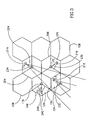
- FIG. 4 is a partially isometric, partially schematic illustration of one cell of a cellular network 100 according to a preferred embodiment of the present invention.
- the embodiment of Fig. 4 illustrates a conventional telephone network in which cellular communication replaces wiring between a base station and a local station.
- the cell preferably includes a base station 302 and three antennae 304, 306 and 308, each of which covers 120° of the cell as indicated by the angle a.
- the cell 300 preferably also includes a plurality of local stations, of which only one, station 310 is shown. Each station is connected to a plurality of local ports, such as the telephone set 312, 314 and 316, typically via wires.
- Each one of the local units 310 includes a directional antenna which communicates with the antenna it generally faces.
- the antenna 318 of the local unit 310 communicates with the antenna 308.
- the angle of operation of the antenna 318 is smaller than 120° to minimize interference with other antennae.
- the angle of operation of the antenna 318 may be 30° - 60° as indicated by the angle ⁇ .
- FIG. 5 is a partially isometric, partially schematic illustration of one cell of a cellular network according to a second preferred embodiment of the present invention.
- the embodiment of Fig. 5 illustrates only one cell of a cellular telephone network, operating with a single vehicle in two locations.
- the cell preferably includes a base station 402 which includes three directional antennae, 404, 406 and 408, and a multiplicity of non-stationary telephones. The operation of only one, the telephone mounted in the vehicle 410 and having an antenna 412, is discussed in detail.
- the antenna 412 is fixed to any suitable mechanism, such as a gyroscopic mechanism, which enables the antenna 412 to rotate in all directions, thereby enabling it to stay directed towards the antenna 408 of the base station 402 independent of the vehicle orientation.
- a suitable mechanism such as a gyroscopic mechanism, which enables the antenna 412 to rotate in all directions, thereby enabling it to stay directed towards the antenna 408 of the base station 402 independent of the vehicle orientation.
- the orientation of the antenna changes as indicated by reference numeral 416, such that it stays directed towards the antenna 408.
Abstract
Description
- The present invention relates generally to cellular communication networks and more particularly to cellular telecommunication networks.
- Cellular communication networks are well known in the art. An example of such a network is a cellular telephone network. Another example is the use of cellular communication in conventional telephone networks, i.e. for replacing physical (wire) connections between a central office and the subscribers units in dense urban areas where wiring is not practical or too costly.
- Since a limited range of frequencies is allocated for each cellular telecommunication network, methods were developed to allow simultaneous use of frequency bands within the allocated range of frequencies. This enables an increased number of users per area to use the network at the same time.
- One method for improving the use of an allocated range of frequencies includes reusing frequency bands within the allocated range of frequencies within the area covered by the network. This method which is known as the "cell method", is schematically shown in Fig. 1A to which reference is now made. The network of Fig. 1A covers an area indicated by
reference numeral 12. Thearea 12 is divided into subareas, termed "cells", such ascell 14. Each cell includes a base station, such asbase station 16, typically in its center. Each base station includes at least one non-directional antenna which communicates with any telephone or local station within the area covered by the cell. - Typically, two adjacent cells, such as
cells cells - In a cellular network the reuse factor N, i.e. the number of distinct frequency bands required for covering the desired area, depends mainly on the capability of the antenna of a base station to cope with interference generated by the network users in other cells using the same frequency band. This capability is a function of the distance D between the interfering user unit and the signal carrier antenna. In a network, such as the
network 10, which employs a reuse factor of 7, interference to an antennae in any cell, such as incell 24, may come from any of the six closest cells which operate on the same frequency band, such as from users incell 28. - The reuse factor also depends on the Carrier to Interference (C/I) ratio which measures the ratio between the carrier signal of an antennae and the interfering noise. For most modern networks, it is desired that the C/I ratio will be 7dB - 15dB and preferably larger than 15db to minimize interferences.
- Therefore, for a state of the art network which employs non-directional antennae, such as the
network 10, a reuse factor of 7, as indicated by the notations F1 - F7, is required in order to achieve a C/I ratio of 18.6dB which meets the desired C/I value of 15dB. - One way to reduce the reuse factor, in order to use a smaller range of frequencies, is to employ directional antennae in each one of the cells instead of the non-directional antennae of the
network 10. A typical prior art cellular network which employs directional antennae is shown in Fig. 1B to which reference is now made. - In the network of Fig. 1B, referenced generally 50, three directional antennae are employed in each cell. Each antenna is directed to a different direction and is using a different frequency band of the three frequency bands denoted F1, F2 and F3.
- In prior art networks which employ directional antennae in adjacent as well as in distant cells, antennae which are directed to the same direction employ a similar frequency band. For example, in the
network 50, theantennae - In the
network 50, an improved C/I ratio relative to a similar network which employs non-directional antennae is achieved since interferences come to any antennae from two adjacent cells and not from six cells as in thenetwork 10 as described in more detail with reference to Fig. 1C. - Reference is now made to Fig. 1C which is a schematic illustration of part of the
network 50 in an operation mode. For clarity of presentation only, four cells in Fig. 3,cells - For each of the
cells cell 54,unit 84 communicates with the antenna which covers the area 164, in thecell 58,unit 82 communicates with the antenna covering thearea 66, in thecell 62,unit 86 communicates with the antenna covering thearea 68 and in thecell 90 andunit 96 communicates with the antenna covering thearea 92. - A characteristic of prior art networks, such as the
network 50 is that interferences to any antennae come from two adjacent cell and also from more distant cells. For example, interferences to the antenna which employs the F3 frequency band in thecell 54 come from theunits cells unit 90 of thecell 92. This is because all the antennae of thecells arrows - For the
network 50 the C/I ratio with comparable technology to that of thenetwork 10 is 19.1dB. For a network likenetwork 50, with a reuse factor of 7, i.e. which employs altogether 21 frequency bands, three per each cell and with a reuse factor of 7, the C/I ratio is 23.4dB. - It is an object of the present invention to provide an improved cellular communication network which employs directional antennae.
- The present inventor has realized that if, in at least two adjacent cells, the direction of antennae which operate in a similar frequency band will be different and not similar as in prior art networks which employ directional antennae, the C/I ratio of the network can be improved as well as the number of users per unit area.
- There is thus provided, in accordance with a preferred embodiment of the present invention, an improved cellular communication network divided into a plurality of cells, each one of the cells including a base station comprising at least two directional antennae, each of which is operative to communicate with a plurality of units, each of the at least two antennae is directed in a different direction and operating in a different frequency band, the network being characterized in that in any adjacent cells of the plurality of cells, antennae which operate in a similar frequency band are directed in a different direction.
- There is also provided, in accordance with a preferred embodiment of the present invention, a method for cellular communication comprising the steps of dividing a cellular communication network into a plurality of cells, each one of the cells including a base station comprising at least two directional antennae operating in a different frequency band, each of which is operative to communicate with a plurality of units, directing each of the at least two antennae in a different direction and operating in a different frequency band such that in any adjacent cells of the plurality of cells antennae which operate in a similar frequency band are directed in a different direction. Preferably, the area covered by the cell is covered by the at least two directional antennae.
- Further, according to a preferred embodiment of the present invention, the area covered by the at least two directional antennae is generally similar to the area covered by the cell.
- Additionally, according to a preferred embodiment of the present invention, each one of the plurality of units may include a directional antennae directed generally in the direction of at least one directional antennae with which it communicates. Further, its angle of operation may be substantially smaller than the angle of operation of the directional antenna with which it communicates.
- Preferably, at least two antennae of each of the base stations may generally cover the range of frequencies allocated for the cellular communication network.
- Still further, according to a preferred embodiment of the present invention, at least one of the plurality of units may be a stationary unit and the network may be a telephone communication network.
- Additionally, according to a preferred embodiment of the present invention, the operation of the at least two antennae in the plurality of cells may be synchronized.
- Finally, according to a preferred embodiment of the present invention, interferences to each antenna come from a single cell which is not adjacent to the cell of the antenna being interfered.
- The present invention will be understood and appreciated more fully from the following detailed description taken in conjunction with the appended drawings in which:
- Fig. 1A is a schematic illustration of a prior art cellular telecommunication network which employs the cell method;
- Fig. 1B is a schematic illustration of a prior art cellular communication which employs the cell method with directional antennae in each cell;
- Fig. 1C is a schematic illustration of the prior art network of Fig. 1 B in an operation mode;
- Fig. 2 is a schematic illustration of a cellular network, constructed and operative in accordance with a preferred embodiment of the present invention;
- Fig. 3 is a schematic illustration of the network of Fig. 2 in an operation mode;
- Fig. 4 is a partially isometric, partially schematic illustration of one cell of a cellular network, according to a preferred embodiment of the present invention; and
- Fig. 5 is a partially isometric, partially schematic illustration of one cell of a cellular network, according to a second preferred embodiment of the present invention.
- Reference is now made to Fig. 2 which is a schematic illustration of a cellular communication network constructed and operative according to a preferred embodiment of the present invention. The network of Fig. 2, generally referenced 100, covers an area which is schematically indicated by the dashed
line 102. Thenetwork 100 preferably comprises a plurality of cells, such ascells network 100 is not limited to any particular number of cells. For exemplary purposes only, twelve cells are shown for thenetwork 100. - The
network 100 may be any suitable communication network, such as a Time Division Multiple Access (TDMA) network, in which all the base stations are synchronized in order to minimize interferences therebetween. - Each one of the cells of the
network 100 preferably include a base station, preferably at its center, as indicated byreference numerals cells base station 114, three antennae (better illustrated in Fig. 4 to which reference is briefly made) are directed in three different directions such that each antennae covers an angle of operation of 120°. The areas covered by the operation of each antennae are referenced 120, 122 and 124, respectively. - The antennae of the base stations, such as the three antennae of the
base station 114, preferably operate in three different frequency bands within the band allocated for the network. The three antennae of thebase station 114 employ the frequency bands F1, F2 and F3 indicated on therespective areas - It will be appreciated that while the
base station 114 includes three directional antennae, the angle of operation of each of which covering an angle of 120°, any number of antennae may be employed in thenetwork 100 provided that together they cover the area of the cell, i.e. they provide a coverage of 360°. - It is a particular feature of the
network 100, that for at least two adjacent cells, the directions of the antennae which operate with a similar frequency band is different, and therefore, in contrast to prior art networks, such asnetwork 50, the areas covered thereby are in different orientations. For example, thearea 120 covered by the antennae of thecell 104 which employ the F3 frequency band, is above thebase station 114 while thearea 126 covered by the antennae which employ the F3 frequency band in thecell 106 is on the left of thebase station 116. - It will be appreciated that while the direction of the antennae which employ the same frequency band in two adjacent cells is different, the antennae of cells which are distanced one from the other may be directed to the same direction.
- Reference is now made to Fig. 3 which is a schematic illustration of part of the
network 100 in an operation mode. For clarity of presentation only, three cells in Fig. 3,cells cells - For each of the
cells cell 104,unit 212 communicates with the antenna which covers thearea 124, in thecell 204,unit 214 communicates with the antenna covering thearea 224 and in thecell 206,unit 216 communicates with the antenna covering the area by thearrow 226. - It will be appreciated that one unit which communicates with each antennae is shown here for exemplary purposes only, and that typically, each antennae communicates with a plurality of units within the area which it covers.
- It is a particular feature of the present invention that interferences to any antennae come only from one cell which is not adjacent to the cell of the antenna being interfered. For example, interferences to the antenna which employs the F3 frequency band in the
cell 104 and which is directed in the general direction indicated by thearrow 232 is interfered only from units directed to the antennae which is directed in the general direction ofarrow 236. - It is a particular feature of the present invention that the frequency band reuse scheme avoids interference between users which communicate with antennae which employ the same frequency band in two adjacent cells. For example, the
unit 216 of thecell 206 and theunit 242 of thecell 246 are directed towards their respective antennae (the antennae directed in thedirections cells - It will be appreciated that by employing the antennae direction scheme of the present invention, a significant improvement in the C/I ratio is achieved. For example, by employing the direction scheme of the
network 100, a C/I ratio of 28.6dB is obtained in comparison with the value of 16.1dB for theprior art network 50, without any other modification in the network. - It will be appreciated that the
network 100 may alternatively use, for example, the range of frequencies allocated to theprior art network 10 more effectively. By using 21 frequency bands, each three of which are equivalent in their band width to each one of the frequency bands F1 - F7 of theprior art network 10, more users can be connected to network per unit area. - Reference is now made to Fig. 4 which is a partially isometric, partially schematic illustration of one cell of a
cellular network 100 according to a preferred embodiment of the present invention. The embodiment of Fig. 4 illustrates a conventional telephone network in which cellular communication replaces wiring between a base station and a local station. - The cell, generally referenced 300, preferably includes a
base station 302 and threeantennae cell 300 preferably also includes a plurality of local stations, of which only one,station 310 is shown. Each station is connected to a plurality of local ports, such as the telephone set 312, 314 and 316, typically via wires. - Each one of the
local units 310 includes a directional antenna which communicates with the antenna it generally faces. In Fig. 3 theantenna 318 of thelocal unit 310 communicates with theantenna 308. - It will be appreciated that the angle of operation of the
antenna 318 is smaller than 120° to minimize interference with other antennae. Typically, the angle of operation of theantenna 318 may be 30° - 60° as indicated by the angle β. By using directional antennae for the local antennae, such asantenna 318, their distance of operation increases, and therefore larger cells may be used. - Reference is now made to Fig. 5 which is a partially isometric, partially schematic illustration of one cell of a cellular network according to a second preferred embodiment of the present invention. The embodiment of Fig. 5 illustrates only one cell of a cellular telephone network, operating with a single vehicle in two locations.
- The cell, generally referenced 400, preferably includes a
base station 402 which includes three directional antennae, 404, 406 and 408, and a multiplicity of non-stationary telephones. The operation of only one, the telephone mounted in thevehicle 410 and having anantenna 412, is discussed in detail. - It is a particular feature of the present invention that the
antenna 412 is fixed to any suitable mechanism, such as a gyroscopic mechanism, which enables theantenna 412 to rotate in all directions, thereby enabling it to stay directed towards theantenna 408 of thebase station 402 independent of the vehicle orientation. As illustrated schematically in Fig. 4, when thevehicle 410 changes its orientation as indicated byarrow 414, the orientation of the antenna changes as indicated byreference numeral 416, such that it stays directed towards theantenna 408. - It will be appreciated that the preferred embodiments described hereinabove are described by way of example only and that numerous modifications thereto, all of which fall within the scope of the present invention, exist. A non-limiting example is to use six directional antennae in each of the base stations of the
network 100. Alternatively, any desired reuse factor with any suitable range of frequencies allocated for the network may be employed . - It will also be appreciated that the present invention is not limited to telecommunication networks. Rather, any of the embodiments described hereinabove and any modification thereof may utilize any type of communication network which employs cellular communication.
- It will be appreciated by persons skilled in the art that the present invention is not limited by what has been particularly shown and described herein above. Rather the scope of the invention is defined by the claims which follow:
Claims (10)
- In a cellular communication network divided into a plurality of cells, each one of said cells including a base station comprising at least two directional antennae, each of which is operative to communicate with a plurality of units, each of said at least two antennae is directed in a different direction and operating in a different frequency band, the network being characterized that in any adjacent cells of said plurality of cells, antennae which operate in a similar frequency band are directed in a different direction.
- A cellular communication network according to claim 1 wherein for each cell, the area covered by said at least two directional antennae is generally similar to the area covered by said cell.
- A cellular communication network according to any of the previous claims wherein each one of said plurality of units includes a directional antennae directed generally in the direction of said at least one directional antennae with which it communicates.
- A cellular communication network according to claim 3 wherein the angle of operation of each of said at least two antennae of said base station is substantially larger than the angle of operation of said directional antennae of each one of said plurality of units.
- A cellular communication network according to any of the previous claims where each of said base stations includes three directional antennae.
- A cellular communication network according to any of the previous claims wherein the frequency bands employed by said at least two directional antennae generally cover a range of frequencies allocated for said cellular communication network.
- A cellular communication network according to any of the previous claims wherein the operation of said at least two antennae in said plurality of cells is synchronized.
- A method for cellular communication comprising:a. dividing a cellular communication network into a plurality of cells, each one of said cells including a base station comprising at least two directional antennae operating in a different frequency band, each of which is operative to communicate with a plurality of units; andb. directing each of said at least two antennae in a different direction and operating in a different frequency band such that in any adjacent cells of said plurality of cells antennae which operate in a similar frequency band are directed in a different direction.
- A method according to claim 8 and also including the step of generally covering the area covered by said cell by said at least two directional antennae.
- A method according to any of claims 8 - 9 and also including the step of employing in said plurality of units directional antennae directed generally in the direction of said at least one directional antennae with which it communicates.
Applications Claiming Priority (2)
| Application Number | Priority Date | Filing Date | Title |
|---|---|---|---|
| IL11172294 | 1994-11-21 | ||
| IL11172294A IL111722A (en) | 1994-11-21 | 1994-11-21 | Cellular network |
Publications (3)
| Publication Number | Publication Date |
|---|---|
| EP0717577A2 true EP0717577A2 (en) | 1996-06-19 |
| EP0717577A3 EP0717577A3 (en) | 1997-10-15 |
| EP0717577B1 EP0717577B1 (en) | 2002-02-06 |
Family
ID=11066796
Family Applications (1)
| Application Number | Title | Priority Date | Filing Date |
|---|---|---|---|
| EP95308270A Expired - Lifetime EP0717577B1 (en) | 1994-11-21 | 1995-11-17 | Cellular communications network with directional antennae |
Country Status (12)
| Country | Link |
|---|---|
| US (1) | US5890066A (en) |
| EP (1) | EP0717577B1 (en) |
| CN (1) | CN1081879C (en) |
| AR (1) | AR000168A1 (en) |
| AT (1) | ATE213116T1 (en) |
| BR (1) | BR9505252A (en) |
| CZ (1) | CZ288556B6 (en) |
| DE (1) | DE69525321D1 (en) |
| IL (1) | IL111722A (en) |
| PE (1) | PE16197A1 (en) |
| PL (1) | PL179339B1 (en) |
| PT (1) | PT717577E (en) |
Cited By (5)
| Publication number | Priority date | Publication date | Assignee | Title |
|---|---|---|---|---|
| WO2000038452A1 (en) * | 1998-12-22 | 2000-06-29 | Telefonaktiebolaget Lm Ericsson (Publ) | Method and arrangement for transferring data or voice via radio between two nodes in a mobile radio system |
| US6424836B1 (en) | 1999-02-09 | 2002-07-23 | Innowave Eci Wireless Systems Ltd. | Method for allocating frequency channels for sectors of a cell in cellular systems |
| WO2004006467A2 (en) * | 2002-07-02 | 2004-01-15 | Mobile Satellite Ventures, Lp | Staggered sectorization for terrestrial reuse of satellite frequencies |
| US7890098B2 (en) | 2001-09-14 | 2011-02-15 | Atc Technologies, Llc | Staggered sectorization for terrestrial reuse of satellite frequencies |
| US8923850B2 (en) | 2006-04-13 | 2014-12-30 | Atc Technologies, Llc | Systems and methods for controlling base station sectors to reduce potential interference with low elevation satellites |
Families Citing this family (6)
| Publication number | Priority date | Publication date | Assignee | Title |
|---|---|---|---|---|
| US5875391A (en) * | 1996-07-25 | 1999-02-23 | Unisite, Inc. | Method of and apparatus for performing antenna cosite analysis |
| US6311068B1 (en) * | 1998-10-19 | 2001-10-30 | At&T Corp. | Method and apparatus for a high-capacity cellular network by improved sectorization and interleaved channel assignment |
| US6748218B1 (en) | 2000-04-10 | 2004-06-08 | Remec, Inc. | Wireless communication methods and systems using multiple sectored cells |
| US6577869B1 (en) * | 2000-06-29 | 2003-06-10 | Harris Broadband Wireless Access, Inc. | Frequency re-use for TDD applications |
| US7010304B1 (en) * | 2002-09-23 | 2006-03-07 | Cingular Wireless Ii, Llc | Cell planning methods and apparatus, and networks configured based on same |
| US8676214B2 (en) * | 2009-02-12 | 2014-03-18 | Adc Telecommunications, Inc. | Backfire distributed antenna system (DAS) with delayed transport |
Family Cites Families (26)
| Publication number | Priority date | Publication date | Assignee | Title |
|---|---|---|---|---|
| US4144411A (en) * | 1976-09-22 | 1979-03-13 | Bell Telephone Laboratories, Incorporated | Cellular radiotelephone system structured for flexible use of different cell sizes |
| US4128740A (en) * | 1977-02-14 | 1978-12-05 | Motorola, Inc. | Antenna array for a cellular RF communications system |
| US4369520A (en) * | 1979-03-22 | 1983-01-18 | Motorola, Inc. | Instantaneously acquiring sector antenna combining system |
| DE3402941A1 (en) * | 1984-01-28 | 1985-08-08 | Licentia Patent-Verwaltungs-Gmbh, 6000 Frankfurt | DIGITAL CELL RADIO SYSTEM WITH TIME MULTIPLEX |
| JPS6365723A (en) * | 1986-09-05 | 1988-03-24 | Mitsubishi Electric Corp | Mobile radio communication system |
| US5095535A (en) * | 1988-07-28 | 1992-03-10 | Motorola, Inc. | High bit rate communication system for overcoming multipath |
| US5448753A (en) * | 1988-09-05 | 1995-09-05 | Ahl; Karl-Axel | Wide area radio communication network system and method |
| SE8803094D0 (en) * | 1988-09-05 | 1988-09-05 | Joakim Nelson | EXCELLENT WIRELESS TELECOMMUNICATION SYSTEM WITH TIME, FREQUENCY AND SPACE CONTROL |
| US5193109A (en) * | 1989-02-06 | 1993-03-09 | Pactel Corporation | Zoned microcell with sector scanning for cellular telephone system |
| US4932049A (en) * | 1989-02-06 | 1990-06-05 | Pactel Corporation | Cellular telephone system |
| US5073971A (en) * | 1989-09-05 | 1991-12-17 | Motorola, Inc. | Cellular radiotelephone communications system |
| US5161249A (en) * | 1989-12-19 | 1992-11-03 | Northern Telecom Limited | Sectored voice channels with rear lobe protection |
| EP0435283B1 (en) * | 1989-12-28 | 1995-12-20 | Nec Corporation | Antenna arrangement system capable of reducing co-channel interference |
| US5038399A (en) * | 1990-05-21 | 1991-08-06 | Motorola, Inc. | Method for assigning channel reuse levels in a multi-level cellular system |
| CA2023053C (en) * | 1990-08-10 | 1994-06-28 | Frank D. Benner | Method for assigning telecommunications channels in a cellular telephone system |
| GB2270236B (en) * | 1991-02-22 | 1995-06-21 | Motorola Inc | Method of operating a communications system |
| US5164958A (en) * | 1991-05-22 | 1992-11-17 | Cylink Corporation | Spread spectrum cellular handoff method |
| US5212830A (en) * | 1991-05-31 | 1993-05-18 | International Mobile Machines Corporation | Radio frequency communications system |
| JP2949533B2 (en) * | 1991-09-03 | 1999-09-13 | 日本電信電話株式会社 | Mobile communication wireless zone configuration method |
| US5365571A (en) * | 1993-05-24 | 1994-11-15 | Hughes Aircraft Company | Cellular system having frequency plan and cell layout with reduced co-channel interference |
| NZ264830A (en) * | 1993-11-15 | 1996-11-26 | Alcatel Australia | Extending the range of a time division multiple access cellular communication system |
| JP2636718B2 (en) * | 1993-12-27 | 1997-07-30 | 日本電気株式会社 | Mobile communication system |
| JP2885067B2 (en) * | 1994-05-30 | 1999-04-19 | 日本電気株式会社 | Mobile subscriber calling method and mobile communication system |
| US5682147A (en) * | 1995-01-24 | 1997-10-28 | Motorola, Inc. | Method and apparatus for selecting a receive frequency in a communication receiver |
| US5633915A (en) * | 1995-05-16 | 1997-05-27 | Southern Methodist University | Multilayered arrangement for load sharing in a cellular communication system |
| US5612701A (en) * | 1995-09-18 | 1997-03-18 | Motorola, Inc. | Adaptive beam pointing method and apparatus for a communication system |
-
1994
- 1994-11-21 IL IL11172294A patent/IL111722A/en not_active IP Right Cessation
-
1995
- 1995-11-15 CZ CZ19953005A patent/CZ288556B6/en not_active IP Right Cessation
- 1995-11-17 EP EP95308270A patent/EP0717577B1/en not_active Expired - Lifetime
- 1995-11-17 PT PT95308270T patent/PT717577E/en unknown
- 1995-11-17 PL PL95311407A patent/PL179339B1/en not_active IP Right Cessation
- 1995-11-17 DE DE69525321T patent/DE69525321D1/en not_active Expired - Lifetime
- 1995-11-17 AT AT95308270T patent/ATE213116T1/en not_active IP Right Cessation
- 1995-11-20 US US08/561,133 patent/US5890066A/en not_active Expired - Lifetime
- 1995-11-20 AR AR33430195A patent/AR000168A1/en unknown
- 1995-11-21 BR BR9505252A patent/BR9505252A/en not_active IP Right Cessation
- 1995-11-21 CN CN95119747A patent/CN1081879C/en not_active Expired - Lifetime
- 1995-11-21 PE PE1995285174A patent/PE16197A1/en not_active Application Discontinuation
Non-Patent Citations (1)
| Title |
|---|
| None |
Cited By (8)
| Publication number | Priority date | Publication date | Assignee | Title |
|---|---|---|---|---|
| WO2000038452A1 (en) * | 1998-12-22 | 2000-06-29 | Telefonaktiebolaget Lm Ericsson (Publ) | Method and arrangement for transferring data or voice via radio between two nodes in a mobile radio system |
| US6487423B1 (en) | 1998-12-22 | 2002-11-26 | Telefonaktiebolaget Lm Ericsson | Method and an arrangement in a mobile radio system |
| US6424836B1 (en) | 1999-02-09 | 2002-07-23 | Innowave Eci Wireless Systems Ltd. | Method for allocating frequency channels for sectors of a cell in cellular systems |
| US7890098B2 (en) | 2001-09-14 | 2011-02-15 | Atc Technologies, Llc | Staggered sectorization for terrestrial reuse of satellite frequencies |
| WO2004006467A2 (en) * | 2002-07-02 | 2004-01-15 | Mobile Satellite Ventures, Lp | Staggered sectorization for terrestrial reuse of satellite frequencies |
| WO2004006467A3 (en) * | 2002-07-02 | 2004-05-06 | Mobile Satellite Ventures Lp | Staggered sectorization for terrestrial reuse of satellite frequencies |
| US8923850B2 (en) | 2006-04-13 | 2014-12-30 | Atc Technologies, Llc | Systems and methods for controlling base station sectors to reduce potential interference with low elevation satellites |
| US9461806B2 (en) | 2006-04-13 | 2016-10-04 | Atc Technologies, Llc | Providing different transmit and/or receive modes in different sectors of a wireless base station |
Also Published As
| Publication number | Publication date |
|---|---|
| IL111722A (en) | 2000-12-06 |
| PL179339B1 (en) | 2000-08-31 |
| PT717577E (en) | 2002-07-31 |
| PL311407A1 (en) | 1996-05-27 |
| DE69525321D1 (en) | 2002-03-21 |
| IL111722A0 (en) | 1995-01-24 |
| US5890066A (en) | 1999-03-30 |
| CN1081879C (en) | 2002-03-27 |
| CZ300595A3 (en) | 1996-06-12 |
| PE16197A1 (en) | 1997-05-13 |
| CN1132455A (en) | 1996-10-02 |
| BR9505252A (en) | 1997-09-16 |
| EP0717577A3 (en) | 1997-10-15 |
| EP0717577B1 (en) | 2002-02-06 |
| ATE213116T1 (en) | 2002-02-15 |
| AR000168A1 (en) | 1997-05-21 |
| CZ288556B6 (en) | 2001-07-11 |
Similar Documents
| Publication | Publication Date | Title |
|---|---|---|
| CA1253213A (en) | Portable radio telephone system | |
| US6002935A (en) | Wireless communications cellular architecture for improving communications resource allocation | |
| JP3234602B2 (en) | Cellular system | |
| US6078815A (en) | Method and apparatus for allocating radio channels | |
| US4144496A (en) | Mobile communication system and method employing frequency reuse within a geographical service area | |
| US6205337B1 (en) | Use of sectorized polarization diversity as a means of increasing capacity in cellular wireless systems | |
| US6405044B1 (en) | Cellular communications system | |
| US6289221B1 (en) | Mobile radio telephone system | |
| JP2002111627A (en) | Cellular communication system and information transmission method | |
| WO1998033338A2 (en) | Point to multipoint radio access system | |
| WO1991003911A1 (en) | Cellular radiotelephone communications system | |
| EP0717577A2 (en) | Cellular communications network with directional antennae | |
| JP4481508B2 (en) | Adaptation sector | |
| US6418316B2 (en) | Increasing channel capacity of wireless local loop via polarization diversity antenna distribution scheme | |
| US5655216A (en) | Mobile communication system providing for coexistence of both a cellular automobile telephone system and a micro cellular system | |
| CN1226125A (en) | Multi-sector cell pattern for wireless communication system | |
| EP1211908B1 (en) | Interstitial sector system | |
| US6127988A (en) | Fixed wireless base station antenna arrangement | |
| US6131033A (en) | Methods and systems of performing system channel planning for wireless local loop communication | |
| EP0502019A4 (en) | Improved microcell system for cellular telephone systems | |
| US20010012780A1 (en) | Cellular communications frequency plan system | |
| KR0159320B1 (en) | Method and apparatus for a radio remote repeater in a digital cellular radio communication system | |
| EP1064758B1 (en) | Method and system for wireless telecommunications | |
| JP2917906B2 (en) | Mobile radio communication system | |
| JP2917908B2 (en) | Mobile radio communication system |
Legal Events
| Date | Code | Title | Description |
|---|---|---|---|
| PUAI | Public reference made under article 153(3) epc to a published international application that has entered the european phase |
Free format text: ORIGINAL CODE: 0009012 |
|
| AK | Designated contracting states |
Kind code of ref document: A2 Designated state(s): AT BE CH DE DK ES FR GB GR IE IT LI LU MC NL PT SE |
|
| AX | Request for extension of the european patent |
Free format text: SI PAYMENT 951214 |
|
| RAX | Requested extension states of the european patent have changed |
Free format text: SI PAYMENT 951214 |
|
| RAP1 | Party data changed (applicant data changed or rights of an application transferred) |
Owner name: TADIRAN TELECOMMUNICATIONS LIMITED |
|
| PUAL | Search report despatched |
Free format text: ORIGINAL CODE: 0009013 |
|
| AK | Designated contracting states |
Kind code of ref document: A3 Designated state(s): AT BE CH DE DK ES FR GB GR IE IT LI LU MC NL PT SE |
|
| AX | Request for extension of the european patent |
Free format text: SI PAYMENT 951214 |
|
| 17P | Request for examination filed |
Effective date: 19980116 |
|
| RAP1 | Party data changed (applicant data changed or rights of an application transferred) |
Owner name: INNOWAVE TADIRAN TELECOMMUNICATIONS WIRELESS SYSTE |
|
| RAP1 | Party data changed (applicant data changed or rights of an application transferred) |
Owner name: INNOWAVE E C I WIRELESS SYSTEMS LTD. |
|
| 17Q | First examination report despatched |
Effective date: 20000105 |
|
| GRAG | Despatch of communication of intention to grant |
Free format text: ORIGINAL CODE: EPIDOS AGRA |
|
| GRAG | Despatch of communication of intention to grant |
Free format text: ORIGINAL CODE: EPIDOS AGRA |
|
| GRAG | Despatch of communication of intention to grant |
Free format text: ORIGINAL CODE: EPIDOS AGRA |
|
| GRAH | Despatch of communication of intention to grant a patent |
Free format text: ORIGINAL CODE: EPIDOS IGRA |
|
| GRAH | Despatch of communication of intention to grant a patent |
Free format text: ORIGINAL CODE: EPIDOS IGRA |
|
| GRAA | (expected) grant |
Free format text: ORIGINAL CODE: 0009210 |
|
| REG | Reference to a national code |
Ref country code: GB Ref legal event code: IF02 |
|
| AK | Designated contracting states |
Kind code of ref document: B1 Designated state(s): AT BE CH DE DK ES FR GB GR IE IT LI LU MC NL PT SE |
|
| AX | Request for extension of the european patent |
Free format text: SI PAYMENT 19951214 |
|
| PG25 | Lapsed in a contracting state [announced via postgrant information from national office to epo] |
Ref country code: NL Free format text: LAPSE BECAUSE OF FAILURE TO SUBMIT A TRANSLATION OF THE DESCRIPTION OR TO PAY THE FEE WITHIN THE PRESCRIBED TIME-LIMIT Effective date: 20020206 Ref country code: LI Free format text: LAPSE BECAUSE OF FAILURE TO SUBMIT A TRANSLATION OF THE DESCRIPTION OR TO PAY THE FEE WITHIN THE PRESCRIBED TIME-LIMIT Effective date: 20020206 Ref country code: IT Free format text: LAPSE BECAUSE OF FAILURE TO SUBMIT A TRANSLATION OF THE DESCRIPTION OR TO PAY THE FEE WITHIN THE PRE;WARNING: LAPSES OF ITALIAN PATENTS WITH EFFECTIVE DATE BEFORE 2007 MAY HAVE OCCURRED AT ANY TIME BEFORE 2007. THE CORRECT EFFECTIVE DATE MAY BE DIFFERENT FROM THE ONE RECORDED.SCRIBED TIME-LIMIT Effective date: 20020206 Ref country code: GR Free format text: LAPSE BECAUSE OF FAILURE TO SUBMIT A TRANSLATION OF THE DESCRIPTION OR TO PAY THE FEE WITHIN THE PRESCRIBED TIME-LIMIT Effective date: 20020206 Ref country code: FR Free format text: LAPSE BECAUSE OF FAILURE TO SUBMIT A TRANSLATION OF THE DESCRIPTION OR TO PAY THE FEE WITHIN THE PRESCRIBED TIME-LIMIT Effective date: 20020206 Ref country code: CH Free format text: LAPSE BECAUSE OF FAILURE TO SUBMIT A TRANSLATION OF THE DESCRIPTION OR TO PAY THE FEE WITHIN THE PRESCRIBED TIME-LIMIT Effective date: 20020206 Ref country code: BE Free format text: LAPSE BECAUSE OF FAILURE TO SUBMIT A TRANSLATION OF THE DESCRIPTION OR TO PAY THE FEE WITHIN THE PRESCRIBED TIME-LIMIT Effective date: 20020206 Ref country code: AT Free format text: LAPSE BECAUSE OF FAILURE TO SUBMIT A TRANSLATION OF THE DESCRIPTION OR TO PAY THE FEE WITHIN THE PRESCRIBED TIME-LIMIT Effective date: 20020206 |
|
| REF | Corresponds to: |
Ref document number: 213116 Country of ref document: AT Date of ref document: 20020215 Kind code of ref document: T |
|
| REG | Reference to a national code |
Ref country code: CH Ref legal event code: EP |
|
| REF | Corresponds to: |
Ref document number: 69525321 Country of ref document: DE Date of ref document: 20020321 |
|
| PG25 | Lapsed in a contracting state [announced via postgrant information from national office to epo] |
Ref country code: SE Free format text: LAPSE BECAUSE OF FAILURE TO SUBMIT A TRANSLATION OF THE DESCRIPTION OR TO PAY THE FEE WITHIN THE PRESCRIBED TIME-LIMIT Effective date: 20020506 Ref country code: DK Free format text: LAPSE BECAUSE OF FAILURE TO SUBMIT A TRANSLATION OF THE DESCRIPTION OR TO PAY THE FEE WITHIN THE PRESCRIBED TIME-LIMIT Effective date: 20020506 |
|
| PG25 | Lapsed in a contracting state [announced via postgrant information from national office to epo] |
Ref country code: DE Free format text: LAPSE BECAUSE OF FAILURE TO SUBMIT A TRANSLATION OF THE DESCRIPTION OR TO PAY THE FEE WITHIN THE PRESCRIBED TIME-LIMIT Effective date: 20020507 |
|
| NLV1 | Nl: lapsed or annulled due to failure to fulfill the requirements of art. 29p and 29m of the patents act | ||
| REG | Reference to a national code |
Ref country code: PT Ref legal event code: SC4A Free format text: AVAILABILITY OF NATIONAL TRANSLATION Effective date: 20020506 |
|
| REG | Reference to a national code |
Ref country code: CH Ref legal event code: PL |
|
| PG25 | Lapsed in a contracting state [announced via postgrant information from national office to epo] |
Ref country code: ES Free format text: LAPSE BECAUSE OF FAILURE TO SUBMIT A TRANSLATION OF THE DESCRIPTION OR TO PAY THE FEE WITHIN THE PRESCRIBED TIME-LIMIT Effective date: 20020829 |
|
| EN | Fr: translation not filed | ||
| PG25 | Lapsed in a contracting state [announced via postgrant information from national office to epo] |
Ref country code: LU Free format text: LAPSE BECAUSE OF NON-PAYMENT OF DUE FEES Effective date: 20021117 |
|
| PG25 | Lapsed in a contracting state [announced via postgrant information from national office to epo] |
Ref country code: IE Free format text: LAPSE BECAUSE OF NON-PAYMENT OF DUE FEES Effective date: 20021118 |
|
| PLBE | No opposition filed within time limit |
Free format text: ORIGINAL CODE: 0009261 |
|
| STAA | Information on the status of an ep patent application or granted ep patent |
Free format text: STATUS: NO OPPOSITION FILED WITHIN TIME LIMIT |
|
| 26N | No opposition filed |
Effective date: 20021107 |
|
| PG25 | Lapsed in a contracting state [announced via postgrant information from national office to epo] |
Ref country code: MC Free format text: LAPSE BECAUSE OF NON-PAYMENT OF DUE FEES Effective date: 20030601 |
|
| REG | Reference to a national code |
Ref country code: IE Ref legal event code: MM4A |
|
| REG | Reference to a national code |
Ref country code: GB Ref legal event code: 732E |
|
| REG | Reference to a national code |
Ref country code: PT Ref legal event code: PC4A Free format text: ALVARION ISRAEL (2003) LTD. IL Effective date: 20040113 |
|
| PGFP | Annual fee paid to national office [announced via postgrant information from national office to epo] |
Ref country code: PT Payment date: 20051026 Year of fee payment: 11 |
|
| PG25 | Lapsed in a contracting state [announced via postgrant information from national office to epo] |
Ref country code: PT Free format text: LAPSE BECAUSE OF NON-PAYMENT OF DUE FEES Effective date: 20070517 |
|
| REG | Reference to a national code |
Ref country code: PT Ref legal event code: MM4A Free format text: LAPSE DUE TO NON-PAYMENT OF FEES Effective date: 20070517 |
|
| PGFP | Annual fee paid to national office [announced via postgrant information from national office to epo] |
Ref country code: GB Payment date: 20091102 Year of fee payment: 15 |
|
| GBPC | Gb: european patent ceased through non-payment of renewal fee |
Effective date: 20101117 |
|
| PG25 | Lapsed in a contracting state [announced via postgrant information from national office to epo] |
Ref country code: GB Free format text: LAPSE BECAUSE OF NON-PAYMENT OF DUE FEES Effective date: 20101117 |