EP0715280B1 - Method and apparatus for processing image - Google Patents
Method and apparatus for processing image Download PDFInfo
- Publication number
- EP0715280B1 EP0715280B1 EP95921991A EP95921991A EP0715280B1 EP 0715280 B1 EP0715280 B1 EP 0715280B1 EP 95921991 A EP95921991 A EP 95921991A EP 95921991 A EP95921991 A EP 95921991A EP 0715280 B1 EP0715280 B1 EP 0715280B1
- Authority
- EP
- European Patent Office
- Prior art keywords
- view
- data
- virtual
- matrix
- image
- Prior art date
- Legal status (The legal status is an assumption and is not a legal conclusion. Google has not performed a legal analysis and makes no representation as to the accuracy of the status listed.)
- Expired - Lifetime
Links
Images


Classifications
-
- G—PHYSICS
- G06—COMPUTING; CALCULATING OR COUNTING
- G06T—IMAGE DATA PROCESSING OR GENERATION, IN GENERAL
- G06T15/00—3D [Three Dimensional] image rendering
-
- A—HUMAN NECESSITIES
- A63—SPORTS; GAMES; AMUSEMENTS
- A63F—CARD, BOARD, OR ROULETTE GAMES; INDOOR GAMES USING SMALL MOVING PLAYING BODIES; VIDEO GAMES; GAMES NOT OTHERWISE PROVIDED FOR
- A63F13/00—Video games, i.e. games using an electronically generated display having two or more dimensions
- A63F13/40—Processing input control signals of video game devices, e.g. signals generated by the player or derived from the environment
- A63F13/42—Processing input control signals of video game devices, e.g. signals generated by the player or derived from the environment by mapping the input signals into game commands, e.g. mapping the displacement of a stylus on a touch screen to the steering angle of a virtual vehicle
-
- A—HUMAN NECESSITIES
- A63—SPORTS; GAMES; AMUSEMENTS
- A63F—CARD, BOARD, OR ROULETTE GAMES; INDOOR GAMES USING SMALL MOVING PLAYING BODIES; VIDEO GAMES; GAMES NOT OTHERWISE PROVIDED FOR
- A63F13/00—Video games, i.e. games using an electronically generated display having two or more dimensions
- A63F13/45—Controlling the progress of the video game
-
- A—HUMAN NECESSITIES
- A63—SPORTS; GAMES; AMUSEMENTS
- A63F—CARD, BOARD, OR ROULETTE GAMES; INDOOR GAMES USING SMALL MOVING PLAYING BODIES; VIDEO GAMES; GAMES NOT OTHERWISE PROVIDED FOR
- A63F13/00—Video games, i.e. games using an electronically generated display having two or more dimensions
- A63F13/50—Controlling the output signals based on the game progress
- A63F13/52—Controlling the output signals based on the game progress involving aspects of the displayed game scene
- A63F13/525—Changing parameters of virtual cameras
-
- A—HUMAN NECESSITIES
- A63—SPORTS; GAMES; AMUSEMENTS
- A63F—CARD, BOARD, OR ROULETTE GAMES; INDOOR GAMES USING SMALL MOVING PLAYING BODIES; VIDEO GAMES; GAMES NOT OTHERWISE PROVIDED FOR
- A63F13/00—Video games, i.e. games using an electronically generated display having two or more dimensions
- A63F13/55—Controlling game characters or game objects based on the game progress
-
- A—HUMAN NECESSITIES
- A63—SPORTS; GAMES; AMUSEMENTS
- A63F—CARD, BOARD, OR ROULETTE GAMES; INDOOR GAMES USING SMALL MOVING PLAYING BODIES; VIDEO GAMES; GAMES NOT OTHERWISE PROVIDED FOR
- A63F13/00—Video games, i.e. games using an electronically generated display having two or more dimensions
- A63F13/80—Special adaptations for executing a specific game genre or game mode
- A63F13/803—Driving vehicles or craft, e.g. cars, airplanes, ships, robots or tanks
-
- G—PHYSICS
- G06—COMPUTING; CALCULATING OR COUNTING
- G06T—IMAGE DATA PROCESSING OR GENERATION, IN GENERAL
- G06T17/00—Three dimensional [3D] modelling, e.g. data description of 3D objects
-
- A—HUMAN NECESSITIES
- A63—SPORTS; GAMES; AMUSEMENTS
- A63F—CARD, BOARD, OR ROULETTE GAMES; INDOOR GAMES USING SMALL MOVING PLAYING BODIES; VIDEO GAMES; GAMES NOT OTHERWISE PROVIDED FOR
- A63F13/00—Video games, i.e. games using an electronically generated display having two or more dimensions
- A63F13/20—Input arrangements for video game devices
- A63F13/24—Constructional details thereof, e.g. game controllers with detachable joystick handles
-
- A—HUMAN NECESSITIES
- A63—SPORTS; GAMES; AMUSEMENTS
- A63F—CARD, BOARD, OR ROULETTE GAMES; INDOOR GAMES USING SMALL MOVING PLAYING BODIES; VIDEO GAMES; GAMES NOT OTHERWISE PROVIDED FOR
- A63F2300/00—Features of games using an electronically generated display having two or more dimensions, e.g. on a television screen, showing representations related to the game
- A63F2300/10—Features of games using an electronically generated display having two or more dimensions, e.g. on a television screen, showing representations related to the game characterized by input arrangements for converting player-generated signals into game device control signals
- A63F2300/1043—Features of games using an electronically generated display having two or more dimensions, e.g. on a television screen, showing representations related to the game characterized by input arrangements for converting player-generated signals into game device control signals being characterized by constructional details
-
- A—HUMAN NECESSITIES
- A63—SPORTS; GAMES; AMUSEMENTS
- A63F—CARD, BOARD, OR ROULETTE GAMES; INDOOR GAMES USING SMALL MOVING PLAYING BODIES; VIDEO GAMES; GAMES NOT OTHERWISE PROVIDED FOR
- A63F2300/00—Features of games using an electronically generated display having two or more dimensions, e.g. on a television screen, showing representations related to the game
- A63F2300/20—Features of games using an electronically generated display having two or more dimensions, e.g. on a television screen, showing representations related to the game characterised by details of the game platform
- A63F2300/203—Image generating hardware
-
- A—HUMAN NECESSITIES
- A63—SPORTS; GAMES; AMUSEMENTS
- A63F—CARD, BOARD, OR ROULETTE GAMES; INDOOR GAMES USING SMALL MOVING PLAYING BODIES; VIDEO GAMES; GAMES NOT OTHERWISE PROVIDED FOR
- A63F2300/00—Features of games using an electronically generated display having two or more dimensions, e.g. on a television screen, showing representations related to the game
- A63F2300/60—Methods for processing data by generating or executing the game program
- A63F2300/6045—Methods for processing data by generating or executing the game program for mapping control signals received from the input arrangement into game commands
-
- A—HUMAN NECESSITIES
- A63—SPORTS; GAMES; AMUSEMENTS
- A63F—CARD, BOARD, OR ROULETTE GAMES; INDOOR GAMES USING SMALL MOVING PLAYING BODIES; VIDEO GAMES; GAMES NOT OTHERWISE PROVIDED FOR
- A63F2300/00—Features of games using an electronically generated display having two or more dimensions, e.g. on a television screen, showing representations related to the game
- A63F2300/60—Methods for processing data by generating or executing the game program
- A63F2300/66—Methods for processing data by generating or executing the game program for rendering three dimensional images
- A63F2300/6661—Methods for processing data by generating or executing the game program for rendering three dimensional images for changing the position of the virtual camera
-
- A—HUMAN NECESSITIES
- A63—SPORTS; GAMES; AMUSEMENTS
- A63F—CARD, BOARD, OR ROULETTE GAMES; INDOOR GAMES USING SMALL MOVING PLAYING BODIES; VIDEO GAMES; GAMES NOT OTHERWISE PROVIDED FOR
- A63F2300/00—Features of games using an electronically generated display having two or more dimensions, e.g. on a television screen, showing representations related to the game
- A63F2300/80—Features of games using an electronically generated display having two or more dimensions, e.g. on a television screen, showing representations related to the game specially adapted for executing a specific type of game
- A63F2300/8017—Driving on land or water; Flying
Definitions
- the present invention relates to image processing methods and apparatus applicable to game devices which advance a game on a real time basis by displaying an image on a display, and more particularly to an image processing method and apparatus which effectively uses the hardware resources of a game device.
- the invention also relates to a game software storing medium for use with an image processing apparatus.
- a computer game device which is capable of processing a game on a real time basis includes a game device body which utilizes pre-stored game software, a control unit which gives an operational signal used for processing which includes movement of a character in a game, a display which displays an image which expresses images in the development of a game contained in the game device body, and an acoustic unit which generates the necessary sound as the game proceeds.
- Game devices having a clear display screen to providing a more realistic image are popular.
- game devices which use polygon processing are popular as they are capable of expressing three-dimensional image data as a collection of given units providing high visual reality.
- the number of polygons which constitutes an object is increased and the polygon surfaces are coated with a texture to thereby further enhance a realistic image.
- the document EP 0 582 815 A2 describes the problem that in computer graphics applications it is frequently desirable to draw lines, curves and points in three-dimensional space that are spatially coincident with a surface in three-dimensional space, and which are required to be visible on the surface. It is proposed therein to move a surface marking on a surface towards the viewer or away from the viewer, by an amount that it a function or a parameter described below and also a scale factor that expresses a relation ship between the viewer eye coordinated units and display pixel units. The parameter determines a maximum slope for the surface, relative to a viewing plane, such that the step of moving will not course a portion of a surface marking to be obscured by the surface.
- the step further includes a step of applying of a predetermined transformation from a viewer eye coordinate system to a modified viewer eye coordinate system.
- US 4 027 403 A discloses a real-time simulation of point systems having multidirectional points as viewed by a moving observer where data are translated and rotated to correspond to the perspective of the simulated view.
- Another object of the present invention is to provide an image processing method and apparatus which is capable of reducing the image processing load of an object to be displayed in order to thereby display an image having greater reality.
- the virtual camera can be compared to a regular camera in that the former has a viewpoint and an image angle involving the delineation of computer graphics.
- the virtual camera is set by designation of its position, optical axis direction (direction of its lens), image angle (zoom-wide), and twist (rotational angle around the optical axis).
- the virtual cameral implies a virtually set viewpoint.
- the virtual camera can be understood as a visual field direction determination means which determines the visual field direction of the image displayed on the video monitor.
- the object is modeling-converted from a body coordinate system inherent in a figure (object) to a world coordinate system which defines the disposition of the figure in a three-dimensional space.
- the resulting object image is visual field-converted to one belonging to a visual-field coordinate system determined by (the position and angle) of the virtual camera, with this object image being displayed on the monitor 30.
- rotational components of a matrix given by X TM which contains information on the travel or movement of an object in a three-dimensional space, where M is a matrix of information on a virtual camera and T is a conversion matrix, are set so as to form the components of a unit matrix to thereby obtain data on the display of the object which faces in an eye direction at all times.
- An image processing apparatus includes processing means for performing coordinate conversion of the object on the basis of a matrix of information of a virtual camera and for setting the rotational components of the matrix of the coordinate-converted object as components which compose a unit matrix.
- the processing means includes, for example, camera control matrix processing means for obtaining the matrix of information of a virtual camera, and object matrix processing means for obtaining a matrix of information on a point rotated on the basis of the product of the matrix of information of a virtual camera and the conversion matrix and for setting the rotational components of the matrix so as to compose a unit matrix to thereby obtain data relating to the display of the object which faces in the eye direction of the virtual camera at all times.
- An image processing apparatus includes storage means for storing information on the position coordinates and angle of a camera and information on the position coordinates of an object, and object matrix processing means for calculating each angle of a three-dimensional coordinate system which causes the object to face in a desired direction on the basis of the information on the position coordinates and angle of the camera and the information on the position coordinates of the object, obtained from the storage means.
- the rotational components of the display matrix of the object obtained by the coordinate conversion are set so as to compose a unit matrix.
- data on the display of the object which faces in the eye direction of the virtual camera is created at all times.
- the relationship between the camera and the object is such that the object faces the camera at all times.
- required data on the object is only (two-dimensional) data to the front of the object, a large amount of data is not required to be handled. Accordingly, the workload of the operation is kept light.
- the object may be composed of object data displayed in the form of a panel.
- this object can be set so as to face in a predetermined direction at all times at a predetermined position.
- a flat object such as a signboard can be set so as to face in the eye direction at all times.
- the matrix of information on the camera information on the position and rotation of the camera is selectable depending on information on the operation of the game device as requested.
- FIG. 1 shows a game device to which an image processing method and apparatus according to the present invention is applied. Illustrated is a game device which handles, for example, a war tank game, which includes a pattern of explosions caused when a bullet fired from the war tank strikes a target.
- a game device which handles, for example, a war tank game, which includes a pattern of explosions caused when a bullet fired from the war tank strikes a target.
- the game device of FIG. 1 has a housing 1 which forms a cockpit.
- the housing 1 has a bottom 1A and a front 1B which continues to one end of the base 1A so as to be perpendicular to the base.
- the bottom 1A has a player's seat 2 on which the player sits to manipulate the game device.
- the front 1B has a game device body 10 therein.
- a control unit 20 which includes a steering element 20A, an accelerator 20B, three switches including a view change switch 20C; a video monitor 30 and a speaker 40 provided on the upper front.
- the game device deals with a war tank game.
- the steering element 20A is the control element which gives direction data to the game device.
- the tank 31 is displayed as a traveling or moving object (vehicle).
- the tank 31 to be displayed can be depicted schematically, as shown in Fig. 2.
- the tank 31 has a body 32 and a cannon sight 33. When bullet 34 is fired from the tank and hits target 35, a pattern of explosions 36 is displayed.
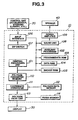
- the game device body 10 includes a central processing unit (CPU) 101, an auxiliary processor 102, a program/data ROM 103, a data RAM 104, a backup RAM 105, an input interface 106, a dip switch 107, a sound unit 108, a power amplifier 109, a polygon parameter memory 110, a coordinate converter 111 called a geometrizer, a polygon data memory 112, a polygon paint unit 113 called a rendering unit, and a frame memory 114.
- CPU central processing unit
- the central processing unit (CPU) 101 is connected through a bus line to the auxiliary processor 102, program/data ROM 103, data RAM 104, backup RAM 105, input interface 106, sound unit 108, and polygon parameter memory 110.
- the input interface 106 is connected to the control unit 20 and the dip switch 107.
- the CPU 101 reads data on a game program contained beforehand in the program/data ROM 103 in cooperation with the auxiliary processor 102 so as to execute the program.
- the game program contains control of the position, direction and angle of the tank as an object displayed on the video monitor 30 and control of the position and angle of a virtual camera which determines the visual field of the display screen. The outline of the control is shown in FIG. 5.
- the sound unit 108 is connected through the power amplifier 109 to the speaker 40.
- An acoustic signal produced by the sound unit 108 is amplified by the amplifier 109 and delivered to the speaker 40.
- An output of the polygon parameter memory 110 is connected to a coordinate conversion unit 111 so that polygon parameters in the memory 110 are delivered to the coordinate conversion unit 111.
- the coordinate conversion unit 111 is connected to a polygon data memory 112 so as to receive polygon data from the memory 112.
- the coordinate converter 111 converts three-dimensional polygon coordinates to be displayed to two-dimensional perspective coordinates on the basis of given polygon parameters and polygon data.
- the output of the coordinate converter 111 is connected to the polygon paint unit 113 such that polygon data on perspective coordinates is delivered to the polygon paint unit 113, which paints the received polygon data with texture data stored in the frame memory 114 to form image data.
- the output of the polygon paint unit 113 is connected to the video monitor 30 on which the image data formed by the paint unit 113 is displayed.
- the accelerator 20B of the control unit 20 outputs an electrical signal indicative of an accelerator opening amount which is reflected in the traveling or moving velocity of the object on the video monitor 30 in response to the player's operation.
- the steering element 20A outputs an electrical signal indicative of a direction ⁇ in which the actions of the object are reflected.
- the view change switch 20C is a switch with which the player designates the position of the virtual camera which determines the visual field of an image displayed on the video monitor 30.
- the central processing unit 101 controls the position and rotation of a virtual camera which determines an eye direction in accordance with a control input from the control unit 20, stores its camera matrix M in the data RAM 104, fetches the camera matrix M and the explosion coordinate data CD, performs operations to convert the coordinates of the explosion pattern (object) and sets the rotational components of a matrix of the explosion pattern in a unit matrix to form an explosion pattern display matrix X, and temporarily stores this matrix in the data RAM 104.
- the central processing unit 101 performs an explosion pattern display process on the basis of the explosion model data MD stored in the program/data ROM 103 and an explosion pattern display matrix X stored in the data RAM 104.
- the appropriate object can be set so as to face the player (in the eye direction) always at a desired position. That is, an explosion pattern display matrix X of the object which faces in a desired direction along the eye direction of the camera is formed at all times. Even when the image pick-up direction of the camera is set in any direction, the object is set at all times so as to face in a direction along the eye direction (the image pick-up direction) of the camera as far as the object is within the view filed of the camera.
- a trapezoid object 510' may be displayed at the left hand of the view.
- a rectangular image 510' may be displayed at the left hand of the view in case rotational coordinates of the object 510 are modified in accordance with this invention to rotate the object 510 as shown in Fig. 6E so that the object faces in a direction along the image pick-up direction of the camera.
- the object 510 is set at all times to face the eye direction of the player.
- the explosion pattern display matrix X is temporarily stored in the data RAM 104 (step 208).
- the central processing unit 101 creates polygon parameters and outputs this data to the polygon parameter memory 110 (steps 211, 212).
- control returns to step 202.
- a matrix M of desired camera information is obtained, and a matrix X which is the product of the camera information matrix M and the conversion matrix T is calculated.
- the rotational components of the matrix X is obtained in which the explosion pattern faces in the eye direction at all times.
- Data on the object which includes the explosion pattern, thus obtained, is delivered through the polygon parameter memory 110 to the coordinate conversion unit (geometrizer) 111, which creates display data at required display coordinates and delivers the data to the polygon paint unit (rendering unit) 113.
- the polygon paint unit 113 applies texture data obtained from the frame memory 114 to the display data to thereby provide display data which includes ornamented polygon data, which is then delivered to the display 30 for displaying purposes.
- FIG. 7A shows a state in which the camera has moved and rotated.
- the explosion pattern is set so as to be at 90 degrees at all times to the eye of the virtual camera.
- the whole image of the explosion pattern can be expressed, using only front data on the explosion pattern. That is, since the object can be moved depending on the viewpoint of the camera, using only data on a predetermined partial area of the explosion pattern, the object can be expressed three-dimensionally, using only data on the predetermined area of the explosion pattern.
- the explosion pattern display matrix X When the explosion pattern display matrix X is calculated, a time-consuming operation on the rotation of an explosion pattern using a rotation conversion matrix R is rendered useless due to a pseudo-operation using a unit matrix.
- the quantity of data required for operation for movement and display of the object involved in the movement of the viewpoint is reduced, the quantity of display data to be handled is also reduced, and hence the calculation load is reduced thereby achieving high-speed calculation.
- the object Since the object is moved depending on the movement of the viewpoint, the object can be expressed as if the object is three-dimensional, by using only data on a part of the object such as front data. Thus, a high-quality image is expressed.
- the game which includes an object for image processing in the present invention is assumed to be a tank game
- the game may be one which shoots solely at an automatically traveling or moving target with a gun.
- the explosion pattern has been illustrated as the object, the object may be any object.
- the objects may be particular enemy tanks or a particular background in the tank game.
- the objects may be standing signboards.
- the objects can be directed at all times so as to face the eye direction and the operation load is reduced, advantageously.
- This embodiment has a structure equal to that of the previous embodiment which handles the tank game.
- the central processing unit 101 performs the process of FIG. 8.
- information on the coordinates of the position of a camera and its angle is obtained in a camera control matrix process.
- a rotational angle of the object about the three-dimensional coordinate axes is calculated on the basis of the position of the object and the position and rotational angle of the camera.
- explosion coordinate data CD is fetched from the RAM 104 to provide object position coordinates (Ox, Oy, Oz) and angle data for causing the explosion pattern to face accurately in the eye direction is created in the object matrix operation (steps 305, 306).
- the creation of the angle data on the explosion pattern is performed with respect to the y, x and z axes as follows.
- the display process is performed with display data which causes the explosion pattern and the flat object to face accurately in a desired direction (in the eye direction), so that the objects face in the eye direction at all times.
- a signboard as a flat object can be directed so as to face the eye direction at all times.
- the object can be set so as to face accurately in a desired direction (in the eye direction) at all times on the basis of data on the position of the object and data on the position and angle of the camera.
Description
- The present invention relates to image processing methods and apparatus applicable to game devices which advance a game on a real time basis by displaying an image on a display, and more particularly to an image processing method and apparatus which effectively uses the hardware resources of a game device. The invention also relates to a game software storing medium for use with an image processing apparatus.
- Generally, a computer game device which is capable of processing a game on a real time basis includes a game device body which utilizes pre-stored game software, a control unit which gives an operational signal used for processing which includes movement of a character in a game, a display which displays an image which expresses images in the development of a game contained in the game device body, and an acoustic unit which generates the necessary sound as the game proceeds.
- Game devices having a clear display screen to providing a more realistic image are popular. Particularly, game devices which use polygon processing are popular as they are capable of expressing three-dimensional image data as a collection of given units providing high visual reality. In a game device using polygon processing, the number of polygons which constitutes an object (a displayed object movable on the display screen) is increased and the polygon surfaces are coated with a texture to thereby further enhance a realistic image.
- As just described above, the demand for increasingly more realistic images requires that hardware should have an ability to reduce processing time as well as to process a greatly increased quantity of data on a real time basis, so that the load on the hardware is greatly increased. This demand is expected to continuously increase in the future, thereby increasing the operational load on the hardware.
- First of all, the game device is required to perform real-time image processing on the basis of data input by the player, with the basic load on the central processing unit being essentially high compared to sole computer graphics image processing.
- In addition, if a game device is composed of a plurality of expensive high-speed operation devices in order to ensure an overwhelming data processing ability such as is present in a flight simulator, the game device would be an expensive commodity and would not satisfy the needs of the market.
- As such, conventional game devices must perform image display processing, whilst limiting the processing ability of its processor or the amount of its data capacity. Thus, the resulting image would give insufficient reality to viewers.
- The document EP 0 582 815 A2 describes the problem that in computer graphics applications it is frequently desirable to draw lines, curves and points in three-dimensional space that are spatially coincident with a surface in three-dimensional space, and which are required to be visible on the surface. It is proposed therein to move a surface marking on a surface towards the viewer or away from the viewer, by an amount that it a function or a parameter described below and also a scale factor that expresses a relation ship between the viewer eye coordinated units and display pixel units. The parameter determines a maximum slope for the surface, relative to a viewing plane, such that the step of moving will not course a portion of a surface marking to be obscured by the surface. The step further includes a step of applying of a predetermined transformation from a viewer eye coordinate system to a modified viewer eye coordinate system. US 4 027 403 A discloses a real-time simulation of point systems having multidirectional points as viewed by a moving observer where data are translated and rotated to correspond to the perspective of the simulated view.
- It is an object of the present invention to provide an image processing method and apparatus which is capable of reducing the image processing load and displaying an image having greater reality.
- Another object of the present invention is to provide an image processing method and apparatus which is capable of reducing the image processing load of an object to be displayed in order to thereby display an image having greater reality.
- These objects are solved by a method as defined in
claim 1 and an apparatus as defined in claim 9. A game software storing medium for use with the image processing apparatus is defined in claim 17. - In an image processing method according to the present invention, rotational components of a matrix of an object obtained by coordinate conversion involving a matrix of information on a virtual camera and a version matrix is set so as to form a unit matrix to thereby provide data for the display of the object. The matrix of camera information includes, for example, information on the position and rotation of the camera.
- The virtual camera can be compared to a regular camera in that the former has a viewpoint and an image angle involving the delineation of computer graphics. The virtual camera is set by designation of its position, optical axis direction (direction of its lens), image angle (zoom-wide), and twist (rotational angle around the optical axis). In other words, the virtual cameral implies a virtually set viewpoint. The virtual camera can be understood as a visual field direction determination means which determines the visual field direction of the image displayed on the video monitor. The object is modeling-converted from a body coordinate system inherent in a figure (object) to a world coordinate system which defines the disposition of the figure in a three-dimensional space. The resulting object image is visual field-converted to one belonging to a visual-field coordinate system determined by (the position and angle) of the virtual camera, with this object image being displayed on the
monitor 30. - In addition, preferably, rotational components of a matrix given by
- An image processing apparatus according to the present invention includes processing means for performing coordinate conversion of the object on the basis of a matrix of information of a virtual camera and for setting the rotational components of the matrix of the coordinate-converted object as components which compose a unit matrix.
- The processing means includes, for example, camera control matrix processing means for obtaining the matrix of information of a virtual camera, and object matrix processing means for obtaining a matrix of information on a point rotated on the basis of the product of the matrix of information of a virtual camera and the conversion matrix and for setting the rotational components of the matrix so as to compose a unit matrix to thereby obtain data relating to the display of the object which faces in the eye direction of the virtual camera at all times.
- An image processing apparatus according to the present invention includes storage means for storing information on the position coordinates and angle of a camera and information on the position coordinates of an object, and object matrix processing means for calculating each angle of a three-dimensional coordinate system which causes the object to face in a desired direction on the basis of the information on the position coordinates and angle of the camera and the information on the position coordinates of the object, obtained from the storage means.
- In the inventive image processing, the rotational components of the display matrix of the object obtained by the coordinate conversion are set so as to compose a unit matrix. Thus, data on the display of the object which faces in the eye direction of the virtual camera is created at all times. Even when the virtual camera is facing in any direction, the relationship between the camera and the object is such that the object faces the camera at all times. Thus, required data on the object is only (two-dimensional) data to the front of the object, a large amount of data is not required to be handled. Accordingly, the workload of the operation is kept light. The object may be composed of object data displayed in the form of a panel. In addition, this object can be set so as to face in a predetermined direction at all times at a predetermined position. A flat object such as a signboard can be set so as to face in the eye direction at all times. As for the matrix of information on the camera, information on the position and rotation of the camera is selectable depending on information on the operation of the game device as requested.
-
- FIG. 1 is a schematic perspective view of a game device according to one embodiment to which the present invention is applied;
- FIG. 2 illustrates objects in the game device;
- FIG. 3 is an electric block diagram indicative of the outline of the game device;
- FIG. 4 is a functional block diagram of a central processing unit and the peripheral devices of the game device;
- FIG. 5 is a flow chart indicative of the outline of processing performed by the central processing unit;
- FIGS. 6A-6C illustrate one example of image processing;
- FIGS. 7A-7C illustrate one example of image processing; and
- FIG. 8 is a flow chart indicative of the outline of the processing performed by a central processing unit of a game device according to when another embodiment of the present invention is applied;
-
- One example of the present invention will be described next with reference to the drawings.
- FIG. 1 shows a game device to which an image processing method and apparatus according to the present invention is applied. Illustrated is a game device which handles, for example, a war tank game, which includes a pattern of explosions caused when a bullet fired from the war tank strikes a target.
- The game device of FIG. 1 has a
housing 1 which forms a cockpit. Thehousing 1 has a bottom 1A and a front 1B which continues to one end of the base 1A so as to be perpendicular to the base. The bottom 1A has a player'sseat 2 on which the player sits to manipulate the game device. The front 1B has agame device body 10 therein. Provided in front of the player'sseat 2 are acontrol unit 20 which includes asteering element 20A, anaccelerator 20B, three switches including a view change switch 20C; avideo monitor 30 and aspeaker 40 provided on the upper front. - The game device deals with a war tank game. The
steering element 20A is the control element which gives direction data to the game device. In this tank game thetank 31 is displayed as a traveling or moving object (vehicle). Thetank 31 to be displayed can be depicted schematically, as shown in Fig. 2. Thetank 31 has abody 32 and acannon sight 33. Whenbullet 34 is fired from the tank and hitstarget 35, a pattern ofexplosions 36 is displayed. - An electrical block diagram of the game device is shown in FIG. 3. The
game device body 10 includes a central processing unit (CPU) 101, anauxiliary processor 102, a program/data ROM 103, adata RAM 104, abackup RAM 105, aninput interface 106, adip switch 107, asound unit 108, apower amplifier 109, apolygon parameter memory 110, a coordinate converter 111 called a geometrizer, apolygon data memory 112, apolygon paint unit 113 called a rendering unit, and aframe memory 114. - The central processing unit (CPU) 101 is connected through a bus line to the
auxiliary processor 102, program/data ROM 103,data RAM 104,backup RAM 105,input interface 106,sound unit 108, andpolygon parameter memory 110. Theinput interface 106 is connected to thecontrol unit 20 and thedip switch 107. TheCPU 101 reads data on a game program contained beforehand in the program/data ROM 103 in cooperation with theauxiliary processor 102 so as to execute the program. The game program contains control of the position, direction and angle of the tank as an object displayed on thevideo monitor 30 and control of the position and angle of a virtual camera which determines the visual field of the display screen. The outline of the control is shown in FIG. 5. - The
sound unit 108 is connected through thepower amplifier 109 to thespeaker 40. An acoustic signal produced by thesound unit 108 is amplified by theamplifier 109 and delivered to thespeaker 40. - An output of the
polygon parameter memory 110 is connected to a coordinate conversion unit 111 so that polygon parameters in thememory 110 are delivered to the coordinate conversion unit 111. The coordinate conversion unit 111 is connected to apolygon data memory 112 so as to receive polygon data from thememory 112. The coordinate converter 111 converts three-dimensional polygon coordinates to be displayed to two-dimensional perspective coordinates on the basis of given polygon parameters and polygon data. The output of the coordinate converter 111 is connected to thepolygon paint unit 113 such that polygon data on perspective coordinates is delivered to thepolygon paint unit 113, which paints the received polygon data with texture data stored in theframe memory 114 to form image data. The output of thepolygon paint unit 113 is connected to the video monitor 30 on which the image data formed by thepaint unit 113 is displayed. - The
accelerator 20B of thecontrol unit 20 outputs an electrical signal indicative of an accelerator opening amount which is reflected in the traveling or moving velocity of the object on the video monitor 30 in response to the player's operation. Similarly, thesteering element 20A outputs an electrical signal indicative of a direction in which the actions of the object are reflected. The view change switch 20C is a switch with which the player designates the position of the virtual camera which determines the visual field of an image displayed on thevideo monitor 30. - The
central processing unit 101 cooperates with theauxiliary processor 102 to execute a game program, which includes the image processing method of the present invention, stored in the program/data ROM 103, as shown in FIG. 4, to thereby functionally realize camera control matrix processing means 121, object matrix processing means 122, and object pattern display means 123. The program/data ROM 103 contains explosion model data MD composed of polygon vertex data which determines the shape of an explosion pattern (object). Thedata RAM 104 contains an explosion pattern display matrix X, and a camera matrix M and explosion coordinate data CD which is position data where an explosion occurs, and, for example, central position coordinates of the explosion model data MD. - As will be described later, the
central processing unit 101 controls the position and rotation of a virtual camera which determines an eye direction in accordance with a control input from thecontrol unit 20, stores its camera matrix M in thedata RAM 104, fetches the camera matrix M and the explosion coordinate data CD, performs operations to convert the coordinates of the explosion pattern (object) and sets the rotational components of a matrix of the explosion pattern in a unit matrix to form an explosion pattern display matrix X, and temporarily stores this matrix in thedata RAM 104. In addition, thecentral processing unit 101 performs an explosion pattern display process on the basis of the explosion model data MD stored in the program/data ROM 103 and an explosion pattern display matrix X stored in thedata RAM 104. Thus, the resulting data is delivered to thepolygon parameter memory 110 and finally to thedisplay 30. Thecentral processing unit 101 calculates the central position of the explosion pattern in accordance with operation information (not shown) as requested, and updates the value of the explosion coordinate data CD in thedata RAM 104 at that time. - The operation of this embodiment will be described principally concentrating on a display process for an explosion pattern as an object with reference to FIGS. 5-7. For the explosion pattern, image data on its front portion should be used.
- The
game device 1 starts the operation of thegame device body 10 in response to the turning-on operation of a power supply, so that thecentral processing unit 101 performs the process shown in FIG. 5 in cooperation with theauxiliary processor 102. - First, the
central processing unit 101 performs a predetermined initializing operation (step 201). Thecentral processing unit 101 then reads from thecontrol unit 20 operation information such as the angle of the steering element turned by the player and the accelerator opening, (step 202), and executes a control operation of a matrix (camera matrix) M about virtual camera information on the basis of the read information (step 203). - This control operation is given by
- The control operation will be described specifically below. In the present embodiment, the action of the
tank 31 is controlled by thesteering element 20A and theaccelerator 20B. Assume therefore that the virtual camera views a scene from the viewpoint of the tank. Thus, the position of the tank can be regarded as the position of the camera (Xp, Yp, Zp), and the rotational angle of the tank can be regarded as the rotational angle of the camera (Xa, Ya, Za). Thus, the travel or movement of the tank due to the accelerator operation is reflected as a change in the camera position (Xp, Yp, Zp) and the rotation of the tank by the steering operation is reflected as a change in the rotational angle of the camera (Xa, Ya, Za). - In this case, the rotational conversion matrix R' is given by the matrix operation of [Ex. 2], and the movement conversion matrix T' is given by the matrix operation of [Ex. 3]. The matrix operation expressions of [Exs. 2 and 3] are described later. The operation expressions or their values of [Ex. 4] and subsequent expressions are described similarly later.
- Since a unit matrix E is expressed by [Ex. 4], the product of the three matrixes of [Exs. 2-4] is a camera matrix M (= R'T'E).
- Data on the calculated camera matrix M is then stored in the data RAM 104 (step 204).
- The
central processing unit 101 then reads the explosion coordinate data CD from the program/data ROM 103 and the camera matrix M from the data RAM 104 (step 205). Thereafter, thecentral processing unit 101 performs coordinate conversion of the explosion pattern which comprises the explosion pattern process (step 206). That is, the central processing unit performs the next matrix operation: - More specifically, when the position of the camera is expressed as (Tx, Ty, Tz), the explosion pattern display matrix X is expressed by [Ex. 5]. Assume in the movement conversion matrix T that its first row is [1 0 0 0], that its second row is [0 1 0 0], that its third row is [0 0 1 1], and that its fourth row is [Tx Ty Tz 1]. By calculating X = TM, using these figures, X is obtained which has the first row [a b c 0], a second row [d e f 0], a third row [g h i 0], and a fourth row [A B C 1]. Thus, by this coordinate conversion process, a matrix based on the movement of the virtual camera is obtained.
- In this embodiment, since no rotation conversion matrix R is used by reason of simplification of a calculation to be described later, what is calculated is only X = TM. By calculating X = TM, the matrix X on camera information has the value of [Ex. 6].
- When the value of the explosion pattern display matrix X is calculated, as describe above, the
central processing unit 101 performs an operation in which the rotational components of the matrix X are set as components of a unit matrix (step 207 of FIG. 5). The respective values of the components a-i of the expression comprise rotation information. Thus, if the rotation information is set as values which compose a unit matrix, as shown in [Ex. 7] below, the rotation information would be lost and the explosion pattern display matrix X necessarily expresses a non-rotation state. - If the object (here, explosion pattern) can face the player in a non-rotated state, the appropriate object can be set so as to face the player (in the eye direction) always at a desired position. That is, an explosion pattern display matrix X of the object which faces in a desired direction along the eye direction of the camera is formed at all times. Even when the image pick-up direction of the camera is set in any direction, the object is set at all times so as to face in a direction along the eye direction (the image pick-up direction) of the camera as far as the object is within the view filed of the camera.
- For example, when the image pick-up direction of the
virtual camera 520 is moved or rotated from the situation as shown in Fig. 6A to a situation as shown in Fig. 7D, the resulting view to be displayed is depicted as shown in Fig. 7E in case rotational coordinates as to theobject 510 are not modified. In the view a trapezoid object 510' may be displayed at the left hand of the view. Differently from the situation as shown in Fig. 7D, a rectangular image 510' may be displayed at the left hand of the view in case rotational coordinates of theobject 510 are modified in accordance with this invention to rotate theobject 510 as shown in Fig. 6E so that the object faces in a direction along the image pick-up direction of the camera. Thus theobject 510 is set at all times to face the eye direction of the player. - The explosion pattern display matrix X is temporarily stored in the data RAM 104 (step 208).
- Thereafter, the explosion pattern display matrix X is read from the
data RAM 104, and the explosion model data MD from the ROM 103 (step 209). Then, the explosion pattern display process is performed (step 210). In this display process, display data is created as the product of the explosion pattern display matrix X and polygon vertex data read from the explosion model data MD. - The
central processing unit 101 creates polygon parameters and outputs this data to the polygon parameter memory 110 (steps 211, 212). - Thereafter, control returns to step 202. By repeating the above, a matrix M of desired camera information is obtained, and a matrix X which is the product of the camera information matrix M and the conversion matrix T is calculated. By setting the rotational components of the matrix X as components which compose a unit matrix, display data is obtained in which the explosion pattern faces in the eye direction at all times.
- Data on the object which includes the explosion pattern, thus obtained, is delivered through the
polygon parameter memory 110 to the coordinate conversion unit (geometrizer) 111, which creates display data at required display coordinates and delivers the data to the polygon paint unit (rendering unit) 113. Thepolygon paint unit 113 applies texture data obtained from theframe memory 114 to the display data to thereby provide display data which includes ornamented polygon data, which is then delivered to thedisplay 30 for displaying purposes. - In the process of FIG. 5, steps 202-204 constitute the camera control matrix processing means 121 of FIG. 4.
Steps - Another matrix calculation of the camera matrix X at
step 206 will be described now for the purpose of comparison. This step can be skipped in this embodiment to reduce the calculation load in accordance with this invention. Assume that the object travels or moves in the three-dimensional space. In this case, an object display matrix X having rotation information at a position to which the object has traveled or moved is given by - A specified calculation example of the rotation conversion matrix R in the coordinate conversion process will be described. First, assume that the matrix M is, for example, a 4 x 4 matrix where elements are a, b, c, ..., k, l, as shown in [Ex. 8]-[Ex. 10].
- Assume that the rotation conversion matrix Rx has a first row [1 0 0 0], a second row [0 cos sin 0], a third row [0 -sin cos 0], and a fourth row [0 0 0 1] By calculating X = Rx·M, using this matrix, X is obtained which has a first row [a b c 0], a second row [A B C 0], a third row [D E F 0] and a fourth row [j k l 1]. As the result of this calculation, the capital letter elements of X are ones influenced by the rotation matrix Rx. Thus, the coordinate conversion has provided a matrix X due to the rotation of the virtual camera with reference to the X-axis direction.
- Similarly, as shown in [Ex. 9], assume that the rotation conversion matrix Ry has a first row [cos 0 -sin 0], a second row [0 1 0 0], a third row [sin 0 cos 0], and a fourth row [0 0 0 1]. By calculating X = Ry·M, using this matrix, X is obtained which has a first row [G H I 0], a second row [d e f 0], a third row [J K L 0] and a fourth row [j k l 1]. As the result of this calculation, the capital letter elements of X are ones influenced by the rotation matrix Ry. Thus, the coordinate conversion has provided a matrix X due to the rotation of the virtual camera with reference to the y-axis direction.
- Similarly, as shown in [Ex. 10], assume that the rotation conversion matrix Rz has a first row [cos sin 0 0], a second row [-sin cos 0 0], a third row [0 0 1 0], and a fourth row [0 0 0 1]. By calculating X = Rz M, using this matrix, X is obtained which has a first row [M N O 0], a second row [P Q R 0], a third row [g h i 0] and a fourth row [j k l 1]. As the result of this calculation, the capital letter elements of X are ones influenced by the rotation matrix Rz. Thus, the coordinate conversion has provided a matrix X due to the rotation of the virtual camera with reference to the z-axis direction.
- As described above, a matrix X having rotational components is obtained by the product of the camera matrix M and the rotation conversion matrix R.
- Subsequently, the operational effects of the present invention will be described specifically with reference to FIGS. 6 and 7.
- First, for comparison, assume that the rotation conversion matrix R of the object is introduced and object matrix processing for X = RTM has been performed.
- Now, as shown in FIG. 6A, assume that an
object 510 has been disposed above the center of anarea 500 and that theviewpoint 520 of the virtual camera faces upward from the center. If a camera matrix M = R' T' E, where E is a unit matrix, is calculated, the resulting matrix M has a first row [1 0 0 0], a second row [0 1 0 0], a third row [0 0 1 0] and a fourth row [0 0 0 1], as shown in FIG. 6B. Thus, when X = RTM is calculated and theobject 510 is observed from thecamera viewpoint 520, a rectangular object 510' is obtained, as shown in FIG. 6C. As just described, anobject 510 having a predetermined size is obtained as an image facing in a predetermined direction by calculation of X = RTM. - Now, as shown in FIG. 7A, assume that an
object 510 has been disposed above the center of anarea 500 and that theviewpoint 520 of the virtual camera faces from the left bottom to the right top. If a camera matrix M = R' T' E where E is a unit matrix is calculated, the resulting matrix M has a first row [A B C 0], a second row [D E F 0], a third row [G H I 0] and a fourth row [a b c 1], as shown in FIG. 7B. Thus, when X = RTM is calculated and theobject 510 is observed from thecamera viewpoint 520, a trapezoid object 510' smaller towards the left and larger towards the right is obtained, as shown in FIG. 7C. As just described, the object 510' is considered in on the basis of information on the position and rotation of the camera to provide a predetermined image. - In contrast, the case where calculation of X = TM which is a simple object matrix process employed in the present embodiment will be described next.
- Assume now that the
area 510 of FIGS. 6A and 7A contains a rectangular polygon. In FIG. 6A, therectangular polygon 510 is expressed by four vertex parameters: - Assume that FIG. 7A shows a state in which the camera has moved and rotated. The four vertexes P1-P4 are converted by a camera matrix obtained as M = R' T' E to parameters (vertexes) P1', P2', P3', and P4', which are expressed as:
- If those parameters are expressed as they are, a matrix of FIG. 7C would be obtained.
- Let M' be a matrix obtained by setting rotation information expressed by A, B, C, D, E, F, G, H, I of a camera matrix M of FIG. 7B in the corresponding components which constitute a unit matrix. The four vertexes are then converted to:
rectangular polygon 510 faces the camera at all times. - As just described above, in the present embodiment, a matrix M of virtual camera information depending on the control provided by the
control unit 20 is calculated, the coordinate conversion X = TM is then performed, and the rotational components of the matrix X are processed so as to have the components of a unit matrix. Thus, by the pseudo-operation based on the unit matrix, the explosion pattern is set so as to be at 90 degrees at all times to the eye of the virtual camera. Thus, the whole image of the explosion pattern can be expressed, using only front data on the explosion pattern. That is, since the object can be moved depending on the viewpoint of the camera, using only data on a predetermined partial area of the explosion pattern, the object can be expressed three-dimensionally, using only data on the predetermined area of the explosion pattern. When the explosion pattern display matrix X is calculated, a time-consuming operation on the rotation of an explosion pattern using a rotation conversion matrix R is rendered useless due to a pseudo-operation using a unit matrix. Thus, the quantity of data required for operation for movement and display of the object involved in the movement of the viewpoint is reduced, the quantity of display data to be handled is also reduced, and hence the calculation load is reduced thereby achieving high-speed calculation. Since the object is moved depending on the movement of the viewpoint, the object can be expressed as if the object is three-dimensional, by using only data on a part of the object such as front data. Thus, a high-quality image is expressed. - While in the embodiment the game which includes an object for image processing in the present invention is assumed to be a tank game, the game may be one which shoots solely at an automatically traveling or moving target with a gun. While the explosion pattern has been illustrated as the object, the object may be any object. For example, the objects may be particular enemy tanks or a particular background in the tank game. Alternatively, the objects may be standing signboards. According to the present invention, the objects can be directed at all times so as to face the eye direction and the operation load is reduced, advantageously.
- Furthermore, another embodiment of the present invention will be described with reference to FIG. 8.
- This embodiment has a structure equal to that of the previous embodiment which handles the tank game. The
central processing unit 101 performs the process of FIG. 8. - In this embodiment, information on the coordinates of the position of a camera and its angle is obtained in a camera control matrix process. In addition, in order to direct the object accurately in the eye direction in the object matrix operation, a rotational angle of the object about the three-dimensional coordinate axes is calculated on the basis of the position of the object and the position and rotational angle of the camera.
- The process of FIG. 8 will be described. First, after a predetermined initialization, the
central processing unit 101 obtains data (Cx, Cy, Cz) on the position of the camera relative to the origin of three-dimensional coordinates and data (Ax, Ay, Az) on the angle of the camera as a camera control matrix process (steps 301-303). Here, for example, Ax shows an angle through which the camera has rotated relative to the x axis of the three-dimensional coordinates. Also, Ay and Az show corresponding angles through which the camera has rotated relative to the y and z axes, respectively. The position data (Cx, Cy, Cz) and angle data (Ax, Ay, Az) on the camera are stored in thedata RAM 104 as a camera matrix M which is the result of the calculation of M = R'T'E (step 304). - When the respective data is obtained in this way, explosion coordinate data CD is fetched from the
RAM 104 to provide object position coordinates (Ox, Oy, Oz) and angle data for causing the explosion pattern to face accurately in the eye direction is created in the object matrix operation (steps 305, 306). The creation of the angle data on the explosion pattern is performed with respect to the y, x and z axes as follows. The rotational angle Yang of the y axis is calculated by: - A rotational angle Xang of the x axis is calculated by
- The rotational angle Zang of the z axis is calculated by
- When angle data (Yang, Xang, Zang) for directing the explosion pattern accurately in the eye direction in the object matrix operation is calculated, the coordinate conversion of the explosion pattern is performed by the calculation X = RTM, using the angle data (Yang, Xang, Zang) and the resulting data X is stored (
steps 307, 308). Thereafter, as in the above, data required for the display process is read, and display of the explosion pattern, creation of polygon parameters, and outputting the polygon parameters are performed (steps 309-312). - As just described above, the display process is performed with display data which causes the explosion pattern and the flat object to face accurately in a desired direction (in the eye direction), so that the objects face in the eye direction at all times. For example, a signboard as a flat object can be directed so as to face the eye direction at all times. In the present embodiment, the object can be set so as to face accurately in a desired direction (in the eye direction) at all times on the basis of data on the position of the object and data on the position and angle of the camera.


 where A = aTx + dTy + gTz + j
B = bTx + eTy + hTz + k
C = cTx + fTy +iTz + 1


Claims (26)
- A method for preparing image data for displaying an object in a three-dimensional coordinate space by rotating a two-dimensional image, said two-dimensional image being composed of one side of view data of said object, said method comprising the steps of:wherein one side of view of the object faces in a prescribed direction relative to said viewpoint when said object is within a field of view of said view point.determining a direction of a view point corresponding to a position of a virtual camera; androtating the two-dimensional image of said object to face in the direction of the view point,
- The method of claim 1, wherein the step of rotating the two-dimensional image of said object to face in the direction of the view point, comprises:rotating one side of view data for an explosion object.
- The method of claim 1, wherein the step of rotating the two-dimensional image of said object to face in the direction of the view point, comprises:rotating one side of view data for a background object.
- The method of claim 1, wherein the step of rotating the two-dimensional image of said object to face in the direction of the view point, comprises:rotating one side of view data for an image of a tree.
- The method of claim 1 for producing in an image processing apparatus a view of the object represented by the image data in the virtual three-dimensional coordinate space, the method further comprising the steps of:providing the one side of view data indicative of the one side of view of the object defined in the virtual three-dimensional coordinate space;determining in the virtual three-dimensional coordinate space positional coordinates of the view point, eye direction from said view point, and a view angle to define a field of view to be displayed;modifying rotational coordinates of the object in response to a change in the eye direction from said view point with respect to the object so that said one side of view of the object is kept displayed at all times when the object is within the field of view from said view point; andgenerating the image data for displaying the view of said object based on said modified rotational coordinates.
- The method of claim 5, wherein the rotational coordinates of the object are modified so that said one side of view of the object faces in a direction along said eye direction.
- The method of claim 6, wherein the rotational coordinates of the object are modified so that said one side of view of the object faces said eye direction.
- The method of claim 5, wherein the object is defined two-dimensionally in the virtual three-dimensional coordinate space.
- The method of claim 8, wherein the rotational coordinates of the object are modified so that a normal line of said one side of view of the object defined two-dimensionally faces in a direction along said eye direction.
- The method of claim 9, wherein the rotational coordinates of the object are modified so that the normal line of said one side of view of the object faces said eye direction.
- The method of claim 5, wherein the object is defined by the one side of view data defining said one side of view of the object and one side of view data lacks for sides of view of the object other than said one side of view of the object.
- The method of claim 5, further comprising the step of providing image data indicative of a plurality of objects in said virtual three-dimensional coordinate space, said plurality of objects including a particular object defined by one side of view data defining one view side thereof.
- An apparatus for preparing image data for displaying an object in a three-dimensional coordinate space by rotating a two-dimensional image, said two-dimensional image being composed of one side of view data of said object, said apparatus comprising:wherein one side of view of the object faces in a prescribed direction relative to said viewpoint when said object is within a field of view of said view point.means for determining a direction of a view point corresponding to a position of a virtual camera; andmeans for rotating the two-dimensional image of said object to face in the direction of the view point,
- The apparatus of claim 13 being an image processing apparatus for producing a view of an object represented by the image data in a virtual three-dimensional coordinate space, the apparatus further comprising:means for providing the one side of view data indicative of the one side of view of the object defined in the virtual three-dimensional coordinate space;means for determining in the virtual three-dimensional coordinate space positional coordinates of a view point, an eye direction from said view point, and a view angle to define a field of view to be displayed;means for modifying rotational coordinates of the object in response to a change in the eye direction from said view point with respect to said object so that said one side of view of the object is kept displayed at all times when the object is within the field of view from said view point; andmeans for generating the image data for displaying the view of said object based on said modified rotational coordinates.
- The apparatus of claim 14, wherein the rotational coordinates of the object are modified so that said one side of view of the object faces in a direction along said eye direction.
- The apparatus of claim 15, wherein the rotational coordinates of the object are modified so that said one side of view of the object faces said eye direction.
- The apparatus of claim 14, wherein said object is defined two-dimensionally in the virtual three-dimensional coordinate space.
- The apparatus of claim 17, wherein the rotational coordinates of the object are modified so that a normal line of said one side of view of the object defined two-dimensionally faces in a direction along said eye direction.
- The apparatus of claim 18, wherein the rotational coordinates of the object are modified so that the normal line of said one side of view of the object faces said eye direction.
- The apparatus of claim 14, wherein the object is defined by the one side of view data defining said one side of view of the object and one side of view data lacks for other sides of view of the object other than said one side of view of the object.
- The apparatus of claim 14, further comprising means for providing image data defining a plurality of objects in a virtual three-dimensional coordinate space, said plurality of objects including a particular object defined two-dimensional in said virtual three-dimensional space with one side of view data defining one view side thereof.
- A computer readable medium for storing computer program code for executing a method for preparing data for displaying an object in a three-dimensional coordinate space by rotating a two-dimensional image, said two-dimensional image, said two-dimensional image being composed of one side of view data of said object, comprising:wherein one side of view of the object faces in a prescribed direction relative to said viewpoint when said object is within a field of view of said view point.code for determining a direction of a view point corresponding of a position of a virtual camera; andcode for rotating the two-dimensional image of said object to face in the direction of the view point,
- The computer readable medium of claim 22, being a game software storing medium for use with an image processing apparatus with a control unit manipulatable by a player for controlling movement of an object in a virtual three-dimensional coordinate space, said game software storing medium storing programs for executing the steps of:providing image data indicative of a plurality of objects in a virtual three-dimensional coordinate space, said plurality of objects including a particular object defined by one side of view data of one view side thereof;determining in said virtual three-dimensional coordinate space positional coordinates of the view point, an eye direction from said view point, and a view angle to define a field of view to be displayed; andmodifying rotational coordinates of the particular object in response to a change in the eye direction from said view point with respect to said particular object so that said one view side of the particular object is kept displayed at all times when said particular object is positioned within the field of view from said view point.
- A game software storing medium of claim 23, wherein said particular object is defined two-dimensionally with one side of view data of one view side thereof.
- A game software storing medium of claim 23 or 24, wherein said modifying step includes a step of modifying the rotational coordinates of the particular object so that a normal line of said one view side faces in a direction along said eye direction.
- A game software storing medium of claim 24, wherein the rotational coordinates of the particular object are modified so that the normal line of said one view side faces said eye direction.
Applications Claiming Priority (4)
| Application Number | Priority Date | Filing Date | Title |
|---|---|---|---|
| JP160507/94 | 1994-06-20 | ||
| JP16050794 | 1994-06-20 | ||
| JP16050794 | 1994-06-20 | ||
| PCT/JP1995/001219 WO1995035555A1 (en) | 1994-06-20 | 1995-06-20 | Method and apparatus for processing image |
Publications (3)
| Publication Number | Publication Date |
|---|---|
| EP0715280A1 EP0715280A1 (en) | 1996-06-05 |
| EP0715280A4 EP0715280A4 (en) | 1996-08-21 |
| EP0715280B1 true EP0715280B1 (en) | 2003-05-21 |
Family
ID=15716448
Family Applications (1)
| Application Number | Title | Priority Date | Filing Date |
|---|---|---|---|
| EP95921991A Expired - Lifetime EP0715280B1 (en) | 1994-06-20 | 1995-06-20 | Method and apparatus for processing image |
Country Status (6)
| Country | Link |
|---|---|
| US (1) | US5971852A (en) |
| EP (1) | EP0715280B1 (en) |
| KR (1) | KR100274444B1 (en) |
| CN (2) | CN1087854C (en) |
| DE (1) | DE69530824D1 (en) |
| WO (1) | WO1995035555A1 (en) |
Families Citing this family (21)
| Publication number | Priority date | Publication date | Assignee | Title |
|---|---|---|---|---|
| US6582308B1 (en) * | 1997-03-23 | 2003-06-24 | Kabushiki Kaisha Sega Enterprises | Image processing device and character aspect design device |
| JP3103322B2 (en) | 1997-05-23 | 2000-10-30 | コナミ株式会社 | Shooting game device, shooting game image display method, and readable recording medium |
| JP4035867B2 (en) * | 1997-09-11 | 2008-01-23 | 株式会社セガ | Image processing apparatus, image processing method, and medium |
| JP3342393B2 (en) * | 1998-03-19 | 2002-11-05 | 株式会社コナミコンピュータエンタテインメントジャパン | Video game device, computer-readable recording medium |
| TW401699B (en) * | 1998-04-01 | 2000-08-11 | Koninkl Philips Electronics Nv | A method and device for generating display frames from a sequence of source frames through synthesizing one or more intermediate frames exclusively from an immediately preceding source frame |
| EP1669930A3 (en) * | 1998-05-20 | 2006-09-06 | Sega Enterprises, Ltd. | Image processing unit, game machine, image processing method, and recording medium |
| JP2000200361A (en) | 1998-08-07 | 2000-07-18 | Sega Enterp Ltd | Image processor and information recording medium |
| US6350199B1 (en) * | 1999-03-16 | 2002-02-26 | International Game Technology | Interactive gaming machine and method with customized game screen presentation |
| EP1079332A1 (en) * | 1999-08-25 | 2001-02-28 | M.M. Multimedia A/S | Method of rendering states of a system |
| JP3321570B2 (en) * | 1999-09-14 | 2002-09-03 | 株式会社ソニー・コンピュータエンタテインメント | Moving image creation method, storage medium, and program execution device |
| JP3822776B2 (en) * | 2000-03-29 | 2006-09-20 | 株式会社バンダイナムコゲームス | GAME DEVICE AND INFORMATION STORAGE MEDIUM |
| JP3732168B2 (en) | 2001-12-18 | 2006-01-05 | 株式会社ソニー・コンピュータエンタテインメント | Display device, display system and display method for objects in virtual world, and method for setting land price and advertising fee in virtual world where they can be used |
| JP4096622B2 (en) | 2002-05-21 | 2008-06-04 | 株式会社セガ | Image processing method and apparatus, program, and recording medium |
| JP3686920B2 (en) * | 2002-05-21 | 2005-08-24 | コナミ株式会社 | 3D image processing program, 3D image processing method, and video game apparatus |
| JP4563266B2 (en) * | 2005-06-29 | 2010-10-13 | 株式会社コナミデジタルエンタテインメント | NETWORK GAME SYSTEM, GAME DEVICE, GAME DEVICE CONTROL METHOD, AND PROGRAM |
| JP4732925B2 (en) * | 2006-03-09 | 2011-07-27 | イマグノーシス株式会社 | Medical image display method and program thereof |
| US8319771B2 (en) * | 2008-09-30 | 2012-11-27 | Disney Enterprises, Inc. | Computer modelled environment |
| TWI493500B (en) * | 2009-06-18 | 2015-07-21 | Mstar Semiconductor Inc | Image processing method and related apparatus for rendering two-dimensional image to show three-dimensional effect |
| CN102238313A (en) * | 2010-04-22 | 2011-11-09 | 扬智科技股份有限公司 | Method for generating image transformation matrix as well as image transformation method and device |
| JP5905421B2 (en) * | 2013-09-03 | 2016-04-20 | 株式会社ア−キテック | Three-dimensional drawing system and program thereof |
| US11638872B1 (en) * | 2021-10-18 | 2023-05-02 | Electronic Arts Inc. | Videographer mode in online games |
Family Cites Families (15)
| Publication number | Priority date | Publication date | Assignee | Title |
|---|---|---|---|---|
| US4027403A (en) * | 1975-03-12 | 1977-06-07 | The Singer Company | Real-time simulation of point system having multidirectional points as viewed by a moving observer |
| JPH0614336B2 (en) * | 1984-09-07 | 1994-02-23 | 株式会社日立製作所 | Design support method |
| JPS6182278A (en) * | 1984-09-29 | 1986-04-25 | Toshiba Corp | Three-dimension coordinate converter |
| JPS6266382A (en) * | 1985-09-19 | 1987-03-25 | Fujitsu Ltd | Distortion prevention system for rotary graphic form |
| GB2181929B (en) * | 1985-10-21 | 1989-09-20 | Sony Corp | Methods of and apparatus for video signal processing |
| US4811245A (en) * | 1985-12-19 | 1989-03-07 | General Electric Company | Method of edge smoothing for a computer image generation system |
| JPH0668758B2 (en) * | 1986-01-07 | 1994-08-31 | 株式会社日立製作所 | Cursor control method and three-dimensional graphic display device |
| US5003498A (en) * | 1986-01-13 | 1991-03-26 | Hitachi, Ltd. | Graphic display method |
| US5001663A (en) * | 1989-05-03 | 1991-03-19 | Eastman Kodak Company | Programmable digital circuit for performing a matrix multiplication |
| US5261820A (en) * | 1990-12-21 | 1993-11-16 | Dynamix, Inc. | Computer simulation playback method and simulation |
| FR2675977B1 (en) * | 1991-04-26 | 1997-09-12 | Inst Nat Audiovisuel | METHOD FOR MODELING A SHOOTING SYSTEM AND METHOD AND SYSTEM FOR PRODUCING COMBINATIONS OF REAL IMAGES AND SYNTHESIS IMAGES. |
| JP2760253B2 (en) * | 1992-07-14 | 1998-05-28 | 住友電気工業株式会社 | Road moving image creation method and in-vehicle navigation device to which the method is applied |
| US5379370A (en) * | 1992-07-17 | 1995-01-03 | International Business Machines Corporation | Method and apparatus for drawing lines, curves, and points coincident with a surface |
| JPH0812687B2 (en) * | 1992-11-27 | 1996-02-07 | 日本電気株式会社 | Symbol display method on 3D map |
| US5583977A (en) * | 1993-10-21 | 1996-12-10 | Taligent, Inc. | Object-oriented curve manipulation system |
-
1995
- 1995-06-20 EP EP95921991A patent/EP0715280B1/en not_active Expired - Lifetime
- 1995-06-20 DE DE69530824T patent/DE69530824D1/en not_active Expired - Lifetime
- 1995-06-20 WO PCT/JP1995/001219 patent/WO1995035555A1/en active IP Right Grant
- 1995-06-20 US US08/596,324 patent/US5971852A/en not_active Expired - Fee Related
- 1995-06-20 CN CN95190555A patent/CN1087854C/en not_active Expired - Fee Related
- 1995-06-20 KR KR1019960700837A patent/KR100274444B1/en not_active IP Right Cessation
-
2002
- 2002-05-16 CN CNB021202141A patent/CN1205594C/en not_active Expired - Fee Related
Also Published As
| Publication number | Publication date |
|---|---|
| KR960704284A (en) | 1996-08-31 |
| EP0715280A4 (en) | 1996-08-21 |
| CN1087854C (en) | 2002-07-17 |
| CN1399230A (en) | 2003-02-26 |
| US5971852A (en) | 1999-10-26 |
| KR100274444B1 (en) | 2000-12-15 |
| WO1995035555A1 (en) | 1995-12-28 |
| EP0715280A1 (en) | 1996-06-05 |
| DE69530824D1 (en) | 2003-06-26 |
| CN1205594C (en) | 2005-06-08 |
| CN1129482A (en) | 1996-08-21 |
Similar Documents
| Publication | Publication Date | Title |
|---|---|---|
| EP0715280B1 (en) | Method and apparatus for processing image | |
| US5616079A (en) | Three-dimensional games machine | |
| USRE41414E1 (en) | Virtual image generation apparatus and method | |
| US5841441A (en) | High-speed three-dimensional texture mapping systems and methods | |
| JP3056256B2 (en) | Three-dimensional simulator device and image synthesizing method | |
| US5936630A (en) | Method of and apparatus for performing perspective transformation of visible stimuli | |
| US6667741B1 (en) | Image generating device and image generating method | |
| US20090244064A1 (en) | Program, information storage medium, and image generation system | |
| US20140002449A1 (en) | System and method for performing three-dimensional motion by two-dimensional character | |
| KR100393504B1 (en) | Object orientation control method and apparatus | |
| EP2158948A2 (en) | Image generation system, image generation method, and information storage medium | |
| US6556201B1 (en) | Image generation system, image display system, computer-readable record medium recording image generation program, and image generation method | |
| JP3989396B2 (en) | Image generation system, program, and information storage medium | |
| JPH09167258A (en) | Method and device for compositing picture and game device | |
| CN112002003A (en) | Spherical panoramic stereo picture generation and interactive display method for virtual 3D scene | |
| JPH0981772A (en) | Method and device for image composition | |
| US6749509B1 (en) | Image processing method and apparatus | |
| US20190243444A1 (en) | Tracking system, tracking method for real-time rendering an image and non-transitory computer-readable medium | |
| JP4592917B2 (en) | Image generating apparatus and game apparatus | |
| JP2001202527A (en) | Method for displaying three-dimensional graphic and three-dimensionally plotting device | |
| CN108986228A (en) | The method and device shown for virtual reality median surface | |
| JPH0724141A (en) | Game device using head-mounted body | |
| JP2883737B2 (en) | Image processing method and apparatus | |
| JP6503098B1 (en) | Image processing apparatus, image processing program and image processing method | |
| JPH0223473A (en) | Variable density adding method and device for three-dimensional form model |
Legal Events
| Date | Code | Title | Description |
|---|---|---|---|
| PUAI | Public reference made under article 153(3) epc to a published international application that has entered the european phase |
Free format text: ORIGINAL CODE: 0009012 |
|
| 17P | Request for examination filed |
Effective date: 19960209 |
|
| AK | Designated contracting states |
Kind code of ref document: A1 Designated state(s): DE ES FR GB IT |
|
| A4 | Supplementary search report drawn up and despatched |
Effective date: 19960704 |
|
| AK | Designated contracting states |
Kind code of ref document: A4 Designated state(s): DE ES FR GB IT |
|
| 17Q | First examination report despatched |
Effective date: 20000217 |
|
| RAP1 | Party data changed (applicant data changed or rights of an application transferred) |
Owner name: SEGA CORPORATION |
|
| GRAH | Despatch of communication of intention to grant a patent |
Free format text: ORIGINAL CODE: EPIDOS IGRA |
|
| GRAH | Despatch of communication of intention to grant a patent |
Free format text: ORIGINAL CODE: EPIDOS IGRA |
|
| GRAH | Despatch of communication of intention to grant a patent |
Free format text: ORIGINAL CODE: EPIDOS IGRA |
|
| GRAA | (expected) grant |
Free format text: ORIGINAL CODE: 0009210 |
|
| AK | Designated contracting states |
Designated state(s): DE ES FR GB IT |
|
| PG25 | Lapsed in a contracting state [announced via postgrant information from national office to epo] |
Ref country code: IT Free format text: LAPSE BECAUSE OF FAILURE TO SUBMIT A TRANSLATION OF THE DESCRIPTION OR TO PAY THE FEE WITHIN THE PRE;WARNING: LAPSES OF ITALIAN PATENTS WITH EFFECTIVE DATE BEFORE 2007 MAY HAVE OCCURRED AT ANY TIME BEFORE 2007. THE CORRECT EFFECTIVE DATE MAY BE DIFFERENT FROM THE ONE RECORDED.SCRIBED TIME-LIMIT Effective date: 20030521 |
|
| REG | Reference to a national code |
Ref country code: GB Ref legal event code: FG4D |
|
| REF | Corresponds to: |
Ref document number: 69530824 Country of ref document: DE Date of ref document: 20030626 Kind code of ref document: P |
|
| PG25 | Lapsed in a contracting state [announced via postgrant information from national office to epo] |
Ref country code: DE Free format text: LAPSE BECAUSE OF FAILURE TO SUBMIT A TRANSLATION OF THE DESCRIPTION OR TO PAY THE FEE WITHIN THE PRESCRIBED TIME-LIMIT Effective date: 20030822 |
|
| PG25 | Lapsed in a contracting state [announced via postgrant information from national office to epo] |
Ref country code: ES Free format text: LAPSE BECAUSE OF FAILURE TO SUBMIT A TRANSLATION OF THE DESCRIPTION OR TO PAY THE FEE WITHIN THE PRESCRIBED TIME-LIMIT Effective date: 20030901 |
|
| ET | Fr: translation filed | ||
| PLBE | No opposition filed within time limit |
Free format text: ORIGINAL CODE: 0009261 |
|
| STAA | Information on the status of an ep patent application or granted ep patent |
Free format text: STATUS: NO OPPOSITION FILED WITHIN TIME LIMIT |
|
| 26N | No opposition filed |
Effective date: 20040224 |
|
| PGFP | Annual fee paid to national office [announced via postgrant information from national office to epo] |
Ref country code: FR Payment date: 20090615 Year of fee payment: 15 |
|
| PGFP | Annual fee paid to national office [announced via postgrant information from national office to epo] |
Ref country code: GB Payment date: 20090618 Year of fee payment: 15 |
|
| GBPC | Gb: european patent ceased through non-payment of renewal fee |
Effective date: 20100620 |
|
| REG | Reference to a national code |
Ref country code: FR Ref legal event code: ST Effective date: 20110228 |
|
| PG25 | Lapsed in a contracting state [announced via postgrant information from national office to epo] |
Ref country code: FR Free format text: LAPSE BECAUSE OF NON-PAYMENT OF DUE FEES Effective date: 20100630 |
|
| PG25 | Lapsed in a contracting state [announced via postgrant information from national office to epo] |
Ref country code: GB Free format text: LAPSE BECAUSE OF NON-PAYMENT OF DUE FEES Effective date: 20100620 |