EP0714676A2 - Dual chamber pacemaker system with improved response to retrograde conduction - Google Patents
Dual chamber pacemaker system with improved response to retrograde conduction Download PDFInfo
- Publication number
- EP0714676A2 EP0714676A2 EP95118788A EP95118788A EP0714676A2 EP 0714676 A2 EP0714676 A2 EP 0714676A2 EP 95118788 A EP95118788 A EP 95118788A EP 95118788 A EP95118788 A EP 95118788A EP 0714676 A2 EP0714676 A2 EP 0714676A2
- Authority
- EP
- European Patent Office
- Prior art keywords
- pacemaker
- ventricular
- interval
- pace
- esc
- Prior art date
- Legal status (The legal status is an assumption and is not a legal conclusion. Google has not performed a legal analysis and makes no representation as to the accuracy of the status listed.)
- Granted
Links
- 230000009977 dual effect Effects 0.000 title claims abstract description 14
- 230000004044 response Effects 0.000 title abstract description 8
- 230000002861 ventricular Effects 0.000 claims abstract description 40
- 230000001746 atrial effect Effects 0.000 claims abstract description 31
- 210000002837 heart atrium Anatomy 0.000 claims description 7
- 230000001360 synchronised effect Effects 0.000 abstract description 12
- 230000002269 spontaneous effect Effects 0.000 abstract description 3
- 102100026827 Protein associated with UVRAG as autophagy enhancer Human genes 0.000 description 21
- 101710102978 Protein associated with UVRAG as autophagy enhancer Proteins 0.000 description 21
- 238000010586 diagram Methods 0.000 description 14
- 230000006870 function Effects 0.000 description 7
- 238000000034 method Methods 0.000 description 4
- 238000013461 design Methods 0.000 description 3
- 206010051994 Pacemaker syndrome Diseases 0.000 description 2
- 230000008901 benefit Effects 0.000 description 2
- 238000004891 communication Methods 0.000 description 2
- 238000001514 detection method Methods 0.000 description 2
- 206010001115 Adams-Stokes syndrome Diseases 0.000 description 1
- 206010003673 Atrioventricular block complete Diseases 0.000 description 1
- 206010003677 Atrioventricular block second degree Diseases 0.000 description 1
- 206010003668 atrial tachycardia Diseases 0.000 description 1
- 230000000747 cardiac effect Effects 0.000 description 1
- 230000008859 change Effects 0.000 description 1
- 230000001934 delay Effects 0.000 description 1
- 230000003111 delayed effect Effects 0.000 description 1
- 238000009795 derivation Methods 0.000 description 1
- 230000000694 effects Effects 0.000 description 1
- 230000000763 evoking effect Effects 0.000 description 1
- 238000007726 management method Methods 0.000 description 1
- 238000005259 measurement Methods 0.000 description 1
- 238000002156 mixing Methods 0.000 description 1
- 238000012544 monitoring process Methods 0.000 description 1
- 230000008520 organization Effects 0.000 description 1
- 230000033764 rhythmic process Effects 0.000 description 1
- 201000002931 third-degree atrioventricular block Diseases 0.000 description 1
Images

Classifications
-
- A—HUMAN NECESSITIES
- A61—MEDICAL OR VETERINARY SCIENCE; HYGIENE
- A61N—ELECTROTHERAPY; MAGNETOTHERAPY; RADIATION THERAPY; ULTRASOUND THERAPY
- A61N1/00—Electrotherapy; Circuits therefor
- A61N1/18—Applying electric currents by contact electrodes
- A61N1/32—Applying electric currents by contact electrodes alternating or intermittent currents
- A61N1/36—Applying electric currents by contact electrodes alternating or intermittent currents for stimulation
- A61N1/362—Heart stimulators
- A61N1/3621—Heart stimulators for treating or preventing abnormally high heart rate
- A61N1/3622—Heart stimulators for treating or preventing abnormally high heart rate comprising two or more electrodes co-operating with different heart regions
Definitions
- This invention relates to cardiac pacing systems and, more particularly, to dual chamber pacing systems designed to detect retrograde conduction and to respond actively to return to normal synchronous operation.
- VDI or VDD allows the atrium to control the heart's response rate, the ventricle being paced at the atrial rate up to a predetermined upper rate limit.
- Such synchronous pacers have incorporated means for dealing with high atrial rates, including “block” and “Wenckebach” techniques.
- A-V or dual chamber pacer Another form of A-V or dual chamber pacer that has been utilized is the sequential pacemaker (DVI), which paces both the atrium and the ventricle with an appropriate A-V delay which is timed by the pacemaker.
- DVI sequential pacemaker
- a number of commercial pacemakers have been introduced which are programmable to these and other known pacing modes. Each of the various operating modes is particularly adapted to certain circumstances that may arise in a given patient.
- the DDDR pacemaker has come to prominence.
- this type of pacemaker there is provided one or more sensors which enable the pacemaker to be rate responsive, such that the pacing interval, or escape interval, is varied as a function of one or more sensed rate-indicating parameters, rather than being fixed at a programmed value.
- both atrial and ventricular natural beats may occur so long as they occur prior to the respective rate responsive escape interval. See U.S. Patents 4,467,807 and 4,951,667, which are illustrative of dual chamber rate responsive pacemakers.
- a pacemaker when it is desirable to synchronize a delivered ventricular stimulus to a sensed atrial signal whenever possible, at the same time the pacemaker should be controlled to adopt another more optimum response whenever desired.
- a pacemaker detects a condition of retrograde conduction, it is known to switch to a mode of asynchronous ventricular pacing until a natural sinus beat is again detected at a rate which can be tracked.
- Techniques for detecting retrograde conduction (RC) are known, e.g., U.S. Pat. No. 5,247,929. In such a pacemaker, when RC is detected, there remains the task of breaking the retrograde conduction and returning to synchronous tracking.
- VDD(R) pacemaker In a VDD(R) pacemaker, it is necessary to wait for the sinus rhythm to regain control. This normally occurs only when the ventricular rate is sufficiently low. With such sensor rate control, it is possible that a sufficient rate drop will not happen for some time, resulting in pacemaker syndrome. With flywheel control, the rate decrease occurs, but this may take some time, during which again pacemaker syndrome may be manifest.
- a direct mode switch into asynchronous operation causes immediate lower rate ventricular pacing, but it is a matter of chance when asynchronous pacing is regained. There is thus a need for a pacemaker which responds actively by immediately controlling ventricular pacing at a rate designed to position the pacemaker for a return to synchronous operation.
- RC When RC is detected, tracking of atrial senses is stopped, e.g., as in mode switching following start of atrial tachycardia.
- One or more asynchronous ventricular paces are controlled at a sufficiently low rate, or long escape interval, so as to ensure the resumption of synchronous tracking where a normal atrial sense is available.
- the longer ventricular escape interval is calculated by obtaining an A-A interval derived recently from the physiological sinus signals, and adding the VA interval (i.e., the retrograde conduction time) and a minimum value for the AV delay (AV min ).
- the escape interval may be made longer than the A-A interval by a value calculated to restore synchronous tracking after N intervals, assuming that the underlying sinus beats are spontaneously occurring at a constant rate. While applicable to dual chamber pacers generally, the invention is particularly desirable for VDD pacers.
- FIG. 1 is a block diagram of the overall system of the invention, showing the environment in which the pacemaker operates.
- FIG. 2 is a block diagram which illustrates basic components of the pacemaker of this invention, together with leads and a sensor for delivering signals to and/or receiving signals from the patient.
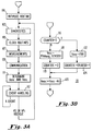
- Figure 3A is a flow diagram showing the main sequential steps carried out each cycle by the pacemaker of this invention.
- Figure 3B is a flow diagram of steps of determining the atrial escape interval (A esc ) and ventricular escape interval (V esc ), illustrating an alternate path for determining V esc when RC has been detected.
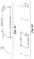
- Figure 4A is a timing diagram which illustrates the optimum ventricular escape interval for regaining synchronous tracking after a retrograde atrial sense
- Figure 4B is a timing diagram illustrating the operation of the pacemaker of this invention wherein delivery three ventricular pace pulses are delivered with an extended V esc designed to regain synchronous tracking of the natural atrial beats.
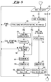
- FIG. 5 is a flow diagram showing the primary steps taken by the pacemaker of this invention in responding to detection of RC by delivery one or more asynchronous ventricular pace pulses at a V esc calculated in accordance with this invention.
- the pacing system of this invention is preferably software-based, i.e., the software controls functions through hardware, as illustrated in Figure 1.
- the pacemaker 50 is shown as having a component hardware portion 51 and a software portion 52, the two portions being interconnected.
- the software is parameter-driven, i.e., there are numerous parameters that control the pacing behavior, diagnostic functions, etc.
- the hardware is interconnected with the patient's heart by one or more electrodes 55, and one or more sensor connections 54.
- the line 54 is illustrated as leading to the heart, as in a QT-type sensor arrangement, but may be attached to the outside case of the pacemaker or may couple to any other available sensors for sensing body parameter information used in rate responsive pacing systems. Further, in the preferred embodiment of the pacing system of this invention, sensor link 54 may comprise a pair of sensors, e.g., QT plus activity, as set forth in U.S. Patent 5,065,759.
- the pacer 50 is in telemetric communication with a programmer 56.
- the user can select parameters and program them through programmer 56, and can also interrogate parameter and diagnostic data from the implanted pacemaker. Interrogated information from the pacer can be coupled by telemetry directly to a printer 58.
- Input/output devices 57 are used to input information by the user to the programmer, or to display information received by the programmer from the pacemaker.
- V-sense block 66 also includes means for picking out and determining the timing of the evoked T wave.
- Microprocessor system 60 which microprocessor has software which is parameter-driven to control the operation of the hardware units.
- Microprocessor system 60 may be interconnected with hardware logic and/or timing circuits 68.
- the microprocessor may have built in timing circuits, or suitably may control external hardware timer circuits.
- Sensor S represents one or more sensors for monitoring one or more body parameters to provide an indication of desired pacing rate.
- the pacemaker of this invention may be rate responsive in the manner as described in the referenced U.S. Patent 5,247,930.
- FIG. 3A there is shown a flow diagram of the main routines taken each cycle by the pacemaker of this invention.
- the routine is initialized at 101. Following this, any diagnostics built into the pacer are performed at block 103; clock routines are done at block 105; measurements are performed and measure data stored at 107; and any communications with an external device, such as programmer 56, are done at step 109.
- the routine then goes to step 111, and determines A esc and V esc for the coming cycle. Of course, for a VDD pacer, no A esc is determined.
- the pacemaker carries out event handling at 112, i.e., it reacts to atrial and/or ventricular senses, and delivers pace pulses as required by timeout of escape intervals. Following the ventricular event, either VS or VP, the pacer returns for the next cycle.
- Fig. 3B these are illustrated the primary steps for determining A esc and V esc , i.e., block 111 of Fig. 3A.
- RC RC counter
- the pacemaker checks to see if an RC counter has a value greater than 0. The role of the counter is explained further in connection with the discussion of Figures 4B and 5; at this point block 116 can simply be understood as the step of checking to see if RC has been detected. If not, the pacemaker goes to step 118, and sets V esc in a conventional manner.
- V esc can be set as a function of the sinus rate, i.e., track the patient's natural rate if available, or can be rate responsive to sensor data.
- a esc is set equal to V esc - AV, where AV can be a programmed value or otherwise determined by the pacer.
- FIG. 4A there is shown a timing diagram illustrating the derivation of optimum of V esc for achieving resync at the next expected sinus sense following a retrograde atrial sense (RAS).
- RAS retrograde atrial sense
- a ventricular pace results in retrograde conduction and an RAS.
- This combination of VP followed by RAS is shown again, the time between the VP and RAS being indicated as VA.
- the timing diagram illustrates the time between the second RAS and the next expected spontaneous sinus beat. This time is expressed as AA Avg , which is obtained by the pacemaker by keeping a running average of the sinus rate, or alternately from the rate response sensor information.
- the calculated escape interval should be of a duration so as to extend beyond the next expected AS by the minimum AV delay, or AV min .
- the calculated shortest value of V esc for delivery of the next VP so as to allow proper sync of the expected sinus beat is VA + AA Avg + AV min .
- the technique of Figure 4B can be used.
- ⁇ (AV min + VA)/N .
- This formula recognizes that the ventricular pace pulses are to be delayed by AV min + VA relative to the natural sinus beats, and this delay is to occur over N cycles.
- ⁇ must be set to (AV min + VA)/N .
- N 3
- the third VP is delivered AV min after the third spontaneous AS.
- FIG. 5 there is shown a flow diagram which represents the specific steps taken in order to respond to retrograde conduction in accordance with this invention. It is to be understood that this flow diagram does not include all steps taken by the pacemaker each cycle, but shows the organization for adapting the ventricular escape interval so as to achieve quick resynchronization after RC.
- Figure 5 assumes a VDD pacemaker, and thus makes no provision for an atrial pulse.
- the pacemaker is waiting for a next event, either atrial or ventricular. If there is an AS, at block 126 the pacemaker determines and stores the VA interval. Then at block 128 the pacemaker goes through atrial sense interpretation, i.e., it examines the relative timing of the atrial sense and categorizes it for logic purposes.
- the pacer also does an RC analysis.
- the analysis for determining RC in the first instance may be any available technique, and as such is not specific to this invention. See, for example, U.S. Patent No. 5,247,929, incorporated herein by reference, which discloses a pacemaker with means for determining RC, as well as atrial sense interpretation generally.
- the pacemaker goes to block 130 and stores information concerning the characteristics of the RAS in order to learn the patient's RAS characteristics and update the RC analysis. Then, at 131, it is determined whether RC just started, i.e., is the counter at 0. If the counter is greater than 0, the pacer is still attempting to break RC, and exits this routine. If the counter is at 0, the pacer goes to step 132 to see if a new attempt at ending RC is allowed. At this point, the pacer determines whether the last previous attempt to break RC was long ago, e.g., some predetermined number of cycles such as 64 or 128. If the answer is no, the pacemaker wants to wait longer before trying again, and branches back to block 125.
- the routine goes to block 134 and determines N, i.e., the number of cycles within which it is aimed to achieve resynchronization. It is preferable for the pacemaker to determine an optimal value for N, such that it is not greater than a maximum programmed value, and such that the resulting lengthened V esc remains less than a programmed length, either expressed in ms or as a percentage (>100%) of the previous V esc or A-A avg . Alternately, N may simply be programmed into the pacer. In most applications, N will be within the range 1-3.
- the counter is set to the determined value of N. Then the V esc (N) is determined at 136, being the lengthened V esc for achieving resync, according to the above formula.
- an RAS has not been identified, but there is a PAC resembling RAS, then it is treated as an RAS and the program branches to block 134. If the atrial sense interpretation reveals an AS that can be tracked, the routine goes to block 140 and updates AA avg . It then goes to block 142 and resets the counter to 0. Then, at block 144, the pacer sets V esc to the normal value of VA-int + AV-int. And lastly, if at block 128 there is no interpretation of an RAS, PAC or AS that can be tracked, the AS is interpreted as "other AS", and the routine returns to 125 and waits. This happens when and if there is a detected AS after RC is detected, as illustrated in Fig. 4B.
- the pacemaker has either sensed a VS, or delivered a VP. The routine then exits.
- the pacer determines a V esc for one or more asynchronous pacer pulses, where V esc is calculated to optimally return the pacer to synchronous tracking of the patient's sinus beats.
Abstract
Description
- This invention relates to cardiac pacing systems and, more particularly, to dual chamber pacing systems designed to detect retrograde conduction and to respond actively to return to normal synchronous operation.
- The advantages of dual chamber pacing, and more particularly pacing in different modes which are selected in response to different patient conditions, is now well recognized in the art. Early pacing systems were solely ventricular, and were sufficient for management of patients with complete heart block and Adams-Stokes attacks. However, ventricular demand pacemakers are not quipped to take advantage of atrial activity, and thus are limited in their efficiency. Subsequently, atrial synchronous, ventricular pacemakers were introduced, having a lead for sensing P signals from the atrium and another for pacing the ventricle after a suitable P-R (A-V) interval. Such a pacemaker, e.g. VDI or VDD, allows the atrium to control the heart's response rate, the ventricle being paced at the atrial rate up to a predetermined upper rate limit. Such synchronous pacers have incorporated means for dealing with high atrial rates, including "block" and "Wenckebach" techniques.
- Another form of A-V or dual chamber pacer that has been utilized is the sequential pacemaker (DVI), which paces both the atrium and the ventricle with an appropriate A-V delay which is timed by the pacemaker. A number of commercial pacemakers have been introduced which are programmable to these and other known pacing modes. Each of the various operating modes is particularly adapted to certain circumstances that may arise in a given patient.
- Since the dual sense-dual pace DDD pacemaker became commercially available, it has gained favor for the reason that it compensates for many of the disadvantages of other pacemaker modes. The classic DDD pacemaker is described in U.S. Patent No. 4,920,965, Funke et al., in some detail. See also U.S. Patents Nos. 4,539,991 and 4,554,921, incorporated herein by reference, which disclose other forms of DDD-type pacemakers.
- More recently, the DDDR pacemaker has come to prominence. In this type of pacemaker, there is provided one or more sensors which enable the pacemaker to be rate responsive, such that the pacing interval, or escape interval, is varied as a function of one or more sensed rate-indicating parameters, rather than being fixed at a programmed value. In the DDDR pacemaker, both atrial and ventricular natural beats may occur so long as they occur prior to the respective rate responsive escape interval. See U.S. Patents 4,467,807 and 4,951,667, which are illustrative of dual chamber rate responsive pacemakers.
- There have also been disclosed multi-mode pacemaker designs having means for switching modes in response to changing patient conditions. Most dual chamber pacemakers are programmable to distinct modes, or switch automatically from one mode to another under certain prescribed conditions. See, for example, U.S. Patent No. 4,527,568, and U.S. Patent 4,920,965. However, there remains a substantial need in the pacing art for sensing the conditions under which a dual chamber pacemaker can or should be controlled to change mode, and for providing optimum flexibility for blending two or more modes of operation. Thus, instead of forcing the pacer to operate in a distinct mode until patient history enables switching to another distinct mode, the pacer would optimally be enabled to react on a cycle-to-cycle basis to sensed events. For example, while it is desirable to synchronize a delivered ventricular stimulus to a sensed atrial signal whenever possible, at the same time the pacemaker should be controlled to adopt another more optimum response whenever desired. Thus, when a pacemaker detects a condition of retrograde conduction, it is known to switch to a mode of asynchronous ventricular pacing until a natural sinus beat is again detected at a rate which can be tracked. Techniques for detecting retrograde conduction (RC) are known, e.g., U.S. Pat. No. 5,247,929. In such a pacemaker, when RC is detected, there remains the task of breaking the retrograde conduction and returning to synchronous tracking. In a VDD(R) pacemaker, it is necessary to wait for the sinus rhythm to regain control. This normally occurs only when the ventricular rate is sufficiently low. With such sensor rate control, it is possible that a sufficient rate drop will not happen for some time, resulting in pacemaker syndrome. With flywheel control, the rate decrease occurs, but this may take some time, during which again pacemaker syndrome may be manifest. A direct mode switch into asynchronous operation causes immediate lower rate ventricular pacing, but it is a matter of chance when asynchronous pacing is regained. There is thus a need for a pacemaker which responds actively by immediately controlling ventricular pacing at a rate designed to position the pacemaker for a return to synchronous operation.
- It is accordingly an object of the invention to provide a pacemaker that has a means for detecting retrograde conduction, and to further provide for efficient control of ventricular pacing so as to regain synchronous tracking as soon as possible, following detection of RC. When RC is detected, tracking of atrial senses is stopped, e.g., as in mode switching following start of atrial tachycardia. One or more asynchronous ventricular paces are controlled at a sufficiently low rate, or long escape interval, so as to ensure the resumption of synchronous tracking where a normal atrial sense is available. The longer ventricular escape interval is calculated by obtaining an A-A interval derived recently from the physiological sinus signals, and adding the VA interval (i.e., the retrograde conduction time) and a minimum value for the AV delay (AVmin). Alternately, the escape interval may be made longer than the A-A interval by a value calculated to restore synchronous tracking after N intervals, assuming that the underlying sinus beats are spontaneously occurring at a constant rate. While applicable to dual chamber pacers generally, the invention is particularly desirable for VDD pacers.
- Figure 1 is a block diagram of the overall system of the invention, showing the environment in which the pacemaker operates.
- Figure 2 is a block diagram which illustrates basic components of the pacemaker of this invention, together with leads and a sensor for delivering signals to and/or receiving signals from the patient.
- Figure 3A is a flow diagram showing the main sequential steps carried out each cycle by the pacemaker of this invention. Figure 3B is a flow diagram of steps of determining the atrial escape interval (Aesc) and ventricular escape interval (Vesc), illustrating an alternate path for determining Vesc when RC has been detected.
- Figure 4A is a timing diagram which illustrates the optimum ventricular escape interval for regaining synchronous tracking after a retrograde atrial sense; Figure 4B is a timing diagram illustrating the operation of the pacemaker of this invention wherein delivery three ventricular pace pulses are delivered with an extended Vesc designed to regain synchronous tracking of the natural atrial beats.
- Figure 5 is a flow diagram showing the primary steps taken by the pacemaker of this invention in responding to detection of RC by delivery one or more asynchronous ventricular pace pulses at a Vesc calculated in accordance with this invention.
- The pacing system of this invention is preferably software-based, i.e., the software controls functions through hardware, as illustrated in Figure 1. Referring specifically to Figure 1, the
pacemaker 50 is shown as having acomponent hardware portion 51 and asoftware portion 52, the two portions being interconnected. The software is parameter-driven, i.e., there are numerous parameters that control the pacing behavior, diagnostic functions, etc. The hardware is interconnected with the patient's heart by one ormore electrodes 55, and one ormore sensor connections 54. As is well understood in the art, for a dual chamber pacemaker, there are generally two leads, an atrial lead and a ventricular lead, each lead having at least one electrode, unipole or bipole, positioned in the heart. Theline 54 is illustrated as leading to the heart, as in a QT-type sensor arrangement, but may be attached to the outside case of the pacemaker or may couple to any other available sensors for sensing body parameter information used in rate responsive pacing systems. Further, in the preferred embodiment of the pacing system of this invention,sensor link 54 may comprise a pair of sensors, e.g., QT plus activity, as set forth in U.S. Patent 5,065,759. - As further illustrated in Figure 1, the
pacer 50 is in telemetric communication with aprogrammer 56. The user can select parameters and program them throughprogrammer 56, and can also interrogate parameter and diagnostic data from the implanted pacemaker. Interrogated information from the pacer can be coupled by telemetry directly to aprinter 58. Input/output devices 57 are used to input information by the user to the programmer, or to display information received by the programmer from the pacemaker. - Referring to Figure 2, there is shown a basic block diagram of primary hardware components of a
DDDR pacer 50. Anatrial generator 61 is shown, having an output connected tolead 62 which communicates with the patient's atrium. AnA-sense amplifier 65 is illustrated also connected toatrial lead 62. A ventricular generator is illustrated which is connected to the patient's ventricle throughlead 64. V-sense amplifier 66 is also connected to lead 64, to receive and sense signals from the patient's ventricle. In one embodiment of this invention which preferably incorporates QT rate control, V-sense block 66 also includes means for picking out and determining the timing of the evoked T wave.Generators microprocessor system 60, which microprocessor has software which is parameter-driven to control the operation of the hardware units.Microprocessor system 60 may be interconnected with hardware logic and/or timingcircuits 68. As affects the scope of this invention, the degree to which software supplants hardware, or vice versa, is a matter of design choice. Thus, for the many timing functions that are carried out in the pacing system of this invention, it is to be understood that the microprocessor may have built in timing circuits, or suitably may control external hardware timer circuits. Software control of pacing function is well known in the art, such that the following detailed discussions of software routines enable one of ordinary skill in this art area to design a system for carrying out the functions within the scope of the invention. Data inputted fromprogrammer 56 is stored in memory associated with microprocessor. - Still referring to Figure 2, there is shown a sensor S indicated as providing an input to
microprocessor system 60. Sensor S represents one or more sensors for monitoring one or more body parameters to provide an indication of desired pacing rate. The pacemaker of this invention may be rate responsive in the manner as described in the referenced U.S. Patent 5,247,930. - Referring now to Figure 3A, there is shown a flow diagram of the main routines taken each cycle by the pacemaker of this invention. The routine is initialized at 101. Following this, any diagnostics built into the pacer are performed at
block 103; clock routines are done atblock 105; measurements are performed and measure data stored at 107; and any communications with an external device, such asprogrammer 56, are done atstep 109. The routine then goes to step 111, and determines Aesc and Vesc for the coming cycle. Of course, for a VDD pacer, no Aesc is determined. Following this, the pacemaker carries out event handling at 112, i.e., it reacts to atrial and/or ventricular senses, and delivers pace pulses as required by timeout of escape intervals. Following the ventricular event, either VS or VP, the pacer returns for the next cycle. - Referring now to Fig. 3B, these are illustrated the primary steps for determining Aesc and Vesc, i.e., block 111 of Fig. 3A. At 116, it is determined whether RC has been detected. In this embodiment the pacemaker checks to see if an RC counter has a value greater than 0. The role of the counter is explained further in connection with the discussion of Figures 4B and 5; at this point block 116 can simply be understood as the step of checking to see if RC has been detected. If not, the pacemaker goes to step 118, and sets Vesc in a conventional manner. Thus, as indicated, Vesc can be set as a function of the sinus rate, i.e., track the patient's natural rate if available, or can be rate responsive to sensor data. Following this, Aesc is set equal to Vesc - AV, where AV can be a programmed value or otherwise determined by the pacer. Alternately, if it is determined at 116 that there is RC, the pacer goes to step 122 and determines Vesc in accordance with this invention, where


step 124 the counter is decremented by 1, such that the special determination of
- Referring now to Figure 4A, there is shown a timing diagram illustrating the derivation of optimum of Vesc for achieving resync at the next expected sinus sense following a retrograde atrial sense (RAS). As illustrated, a ventricular pace results in retrograde conduction and an RAS. This combination of VP followed by RAS is shown again, the time between the VP and RAS being indicated as VA. The timing diagram illustrates the time between the second RAS and the next expected spontaneous sinus beat. This time is expressed as AAAvg, which is obtained by the pacemaker by keeping a running average of the sinus rate, or alternately from the rate response sensor information. As can be seen from the timing diagram, in order to resync at the next expected natural sinus sense (AS), the calculated escape interval should be of a duration so as to extend beyond the next expected AS by the minimum AV delay, or AVmin. Thus, the calculated shortest value of Vesc for delivery of the next VP so as to allow proper sync of the expected sinus beat is


- Referring now to Figure 5, there is shown a flow diagram which represents the specific steps taken in order to respond to retrograde conduction in accordance with this invention. It is to be understood that this flow diagram does not include all steps taken by the pacemaker each cycle, but shows the organization for adapting the ventricular escape interval so as to achieve quick resynchronization after RC. Figure 5 assumes a VDD pacemaker, and thus makes no provision for an atrial pulse.
- At 125 the pacemaker is waiting for a next event, either atrial or ventricular. If there is an AS, at
block 126 the pacemaker determines and stores the VA interval. Then atblock 128 the pacemaker goes through atrial sense interpretation, i.e., it examines the relative timing of the atrial sense and categorizes it for logic purposes. The pacer also does an RC analysis. The analysis for determining RC in the first instance may be any available technique, and as such is not specific to this invention. See, for example, U.S. Patent No. 5,247,929, incorporated herein by reference, which discloses a pacemaker with means for determining RC, as well as atrial sense interpretation generally. - If an RAS is identified, the pacemaker goes to block 130 and stores information concerning the characteristics of the RAS in order to learn the patient's RAS characteristics and update the RC analysis. Then, at 131, it is determined whether RC just started, i.e., is the counter at 0. If the counter is greater than 0, the pacer is still attempting to break RC, and exits this routine. If the counter is at 0, the pacer goes to step 132 to see if a new attempt at ending RC is allowed. At this point, the pacer determines whether the last previous attempt to break RC was long ago, e.g., some predetermined number of cycles such as 64 or 128. If the answer is no, the pacemaker wants to wait longer before trying again, and branches back to block 125. If yes, the routine goes to block 134 and determines N, i.e., the number of cycles within which it is aimed to achieve resynchronization. It is preferable for the pacemaker to determine an optimal value for N, such that it is not greater than a maximum programmed value, and such that the resulting lengthened Vesc remains less than a programmed length, either expressed in ms or as a percentage (>100%) of the previous Vesc or A-Aavg. Alternately, N may simply be programmed into the pacer. In most applications, N will be within the range 1-3. At
block 135, the counter is set to the determined value of N. Then the Vesc (N) is determined at 136, being the lengthened Vesc for achieving resync, according to the above formula. - Returning to block 128, if an RAS has not been identified, but there is a PAC resembling RAS, then it is treated as an RAS and the program branches to block 134. If the atrial sense interpretation reveals an AS that can be tracked, the routine goes to block 140 and updates AAavg. It then goes to block 142 and resets the counter to 0. Then, at
block 144, the pacer sets Vesc to the normal value of VA-int + AV-int. And lastly, if atblock 128 there is no interpretation of an RAS, PAC or AS that can be tracked, the AS is interpreted as "other AS", and the routine returns to 125 and waits. This happens when and if there is a detected AS after RC is detected, as illustrated in Fig. 4B. - Returning to block 125, when the event is a V event, the pacemaker has either sensed a VS, or delivered a VP. The routine then exits.
- There is thus provided a dual chamber pacer, particularly in a VDD embodiment, with an improved capacity for reacting to a detected RC condition. The pacer determines a Vesc for one or more asynchronous pacer pulses, where Vesc is calculated to optimally return the pacer to synchronous tracking of the patient's sinus beats.
Claims (8)
- A dual chamber pacemaker having atrial sense means for sensing signals from a patient's atrium, sinus interval means for determining an interval (A-A Int) representative of the patient's underlying sinus rate, ventricular pace means for generating pace pulses for delivery to the patient's ventricle, control means for controlling the timing of said pace pulses, and interpretation means for interpreting when a said atrial sense can be tracked and when a said atrial sense indicates RC, said control means further comprising tracking means for controlling said pace means to generate pace pulses in tracking relation to sensed atrial signals when said interpreting means interprets that they can be tracked, and asynchronous means for controlling said pace means to deliver at least one asynchronous pulse following an atrial sense interpreted as indicating RC, said asynchronous means further having timing means for controlling said pace means to deliver said at least one pulse at a time more than said sinus interval following said indicating atrial sense.
- The pacemaker as described in claim 1, wherein said timing means controls delivery of said at least one pulse at an escape interval

- The pacemaker as described in claim 1, wherein said timing means controls delivery of N pulses each having an escape interval


- The pacemaker as described in claim 1, wherein said asynchronous means has means for controlling said pace means to deliver at least a next ventricular pace pulse at a V-V interval greater than the last VA interval plus said sinus interval, where VA interval is the time from the prior ventricular pulse to the indicating sense.
- The pacemaker as described in claim 4, wherein sad asynchronous means has means for controlling said ventricular pace means to deliver a plurality of ventricular pace pulses, each at a V-V interval greater than said last VA interval plus said sinus interval.
- The pacemaker as described in claim 4, comprising limit means for limiting said asynchronous means to be operative or no more than N consecutive cycles.
- The pacemaker as described in claim 6, wherein N = 3.
- The pacemaker as described in claim 1, wherein said dual chamber pacemaker is a VDD pacemaker.
Applications Claiming Priority (2)
| Application Number | Priority Date | Filing Date | Title |
|---|---|---|---|
| US348317 | 1994-12-02 | ||
| US08/348,317 US5534017A (en) | 1994-12-02 | 1994-12-02 | Dual chamber pacemaker system with improved response to retrograde conduction |
Publications (3)
| Publication Number | Publication Date |
|---|---|
| EP0714676A2 true EP0714676A2 (en) | 1996-06-05 |
| EP0714676A3 EP0714676A3 (en) | 1998-03-11 |
| EP0714676B1 EP0714676B1 (en) | 2002-04-17 |
Family
ID=23367478
Family Applications (1)
| Application Number | Title | Priority Date | Filing Date |
|---|---|---|---|
| EP95118788A Expired - Lifetime EP0714676B1 (en) | 1994-12-02 | 1995-11-29 | Dual chamber pacemaker system with improved response to retrograde conduction |
Country Status (4)
| Country | Link |
|---|---|
| US (1) | US5534017A (en) |
| EP (1) | EP0714676B1 (en) |
| JP (1) | JPH08252330A (en) |
| DE (1) | DE69526408T2 (en) |
Cited By (2)
| Publication number | Priority date | Publication date | Assignee | Title |
|---|---|---|---|---|
| FR2763247A1 (en) * | 1997-05-16 | 1998-11-20 | Ela Medical Sa | ACTIVE IMPLANTABLE MEDICAL DEVICE, IN PARTICULAR A CARDIAC STIMULATOR, DEFIBRILLATOR AND / OR CARDIOVERTER FOR REDUCING ARRHYTHMIA EPISODES, ESPECIALLY ATRIAL ARRHYTHMIA |
| DE19859651A1 (en) * | 1998-12-15 | 2000-06-21 | Biotronik Mess & Therapieg | Dual-chamber pacemakers |
Families Citing this family (21)
| Publication number | Priority date | Publication date | Assignee | Title |
|---|---|---|---|---|
| FR2734730B1 (en) * | 1995-05-31 | 1997-08-22 | Ela Medical Sa | ACTIVE IMPLANTABLE MEDICAL DEVICE, IN PARTICULAR A CARDIAC STIMULATOR OR DEFRIBRILLATOR |
| US20060247693A1 (en) | 2005-04-28 | 2006-11-02 | Yanting Dong | Non-captured intrinsic discrimination in cardiac pacing response classification |
| US8521284B2 (en) | 2003-12-12 | 2013-08-27 | Cardiac Pacemakers, Inc. | Cardiac response classification using multisite sensing and pacing |
| US7774064B2 (en) | 2003-12-12 | 2010-08-10 | Cardiac Pacemakers, Inc. | Cardiac response classification using retriggerable classification windows |
| US8229561B2 (en) * | 2004-12-15 | 2012-07-24 | Cardiac Pacemakers, Inc. | Atrial retrograde management |
| US7930029B2 (en) | 2004-12-15 | 2011-04-19 | Cardiac Pacemakers, Inc. | Template initialization for evoked response detection |
| US7587240B2 (en) | 2004-12-15 | 2009-09-08 | Cardiac Pacemakers, Inc. | Atrial capture verification |
| US7908006B2 (en) * | 2004-12-15 | 2011-03-15 | Cardiac Pacemakers, Inc. | Cardiac pacing response classification using an adaptable classification interval |
| US7392086B2 (en) | 2005-04-26 | 2008-06-24 | Cardiac Pacemakers, Inc. | Implantable cardiac device and method for reduced phrenic nerve stimulation |
| US7574260B2 (en) | 2005-04-28 | 2009-08-11 | Cardiac Pacemakers, Inc. | Adaptive windowing for cardiac waveform discrimination |
| US7457666B2 (en) | 2005-05-25 | 2008-11-25 | Cardiac Pacemakers, Inc. | Retrograde atrial sensing for identifying sub-threshold atrial pacing |
| US8209013B2 (en) | 2006-09-14 | 2012-06-26 | Cardiac Pacemakers, Inc. | Therapeutic electrical stimulation that avoids undesirable activation |
| US7583996B2 (en) * | 2006-11-15 | 2009-09-01 | Biotronik Crm Patent Ag | Atrial overdrive pacing in non-atrial tracking mode while maintaining AV synchrony |
| US8290590B2 (en) * | 2006-11-17 | 2012-10-16 | Cardiac Pacemakers, Inc. | Dynamic morphology based atrial automatic threshold |
| US7801610B2 (en) * | 2006-11-17 | 2010-09-21 | Cardiac Pacemakers, Inc. | Methods and systems for management of atrial retrograde conduction and pacemaker mediated tachyarrhythmia |
| US8265736B2 (en) | 2007-08-07 | 2012-09-11 | Cardiac Pacemakers, Inc. | Method and apparatus to perform electrode combination selection |
| US9037239B2 (en) | 2007-08-07 | 2015-05-19 | Cardiac Pacemakers, Inc. | Method and apparatus to perform electrode combination selection |
| CN101939051B (en) | 2008-02-14 | 2013-07-10 | 心脏起搏器公司 | Method and apparatus for phrenic stimulation detection |
| US8452405B2 (en) * | 2009-05-05 | 2013-05-28 | Cardiac Pacemakers, Inc. | Methods and systems for mitigating the occurrence of arrhythmia during atrial pacing |
| US9037237B2 (en) * | 2009-07-29 | 2015-05-19 | Medtronic, Inc. | Algorithm to modulate atrial-ventricular delay and rate response based on autonomic function |
| US10864378B2 (en) | 2017-03-09 | 2020-12-15 | Cardiac Pacemakers, Inc. | Pacemaker with diagnostic intrinsic beat search |
Citations (9)
| Publication number | Priority date | Publication date | Assignee | Title |
|---|---|---|---|---|
| US4467807A (en) | 1981-11-23 | 1984-08-28 | Medtronic, Inc. | Rate adaptive demand pacemaker |
| US4527568A (en) | 1983-12-27 | 1985-07-09 | Vitafin N.V. | Dual chamber pacer with alternative rate adaptive means and method |
| US4539991A (en) | 1983-02-11 | 1985-09-10 | Vitafin N.V. | Dual chamber pacemaker |
| US4554921A (en) | 1983-02-11 | 1985-11-26 | Vitafin N.V. | Dual chamber pacemaker with automatic high rate limit mode determination |
| US4920965A (en) | 1987-11-25 | 1990-05-01 | Medtronic, Inc. | Dual chamber pacemaker with adaptive atrial escape interval |
| US4951667A (en) | 1987-11-25 | 1990-08-28 | Medtronic, Inc. | Dual chamber activity responsive pacer |
| US5065759A (en) | 1990-08-30 | 1991-11-19 | Vitatron Medical B.V. | Pacemaker with optimized rate responsiveness and method of rate control |
| US5247930A (en) | 1992-02-04 | 1993-09-28 | Vitatron Medical, B.V. | Dual chamber pacing system with dynamic physiological tracking and method of timing delivered stimulus for optimized synchronous pacing |
| US5247929A (en) | 1992-02-04 | 1993-09-28 | Vitatron Medical, B.V. | Dual chamber pacemaker with AV extension and PMT control |
Family Cites Families (6)
| Publication number | Priority date | Publication date | Assignee | Title |
|---|---|---|---|---|
| US4401119A (en) * | 1981-02-17 | 1983-08-30 | Medtronic, Inc. | Prolongation of timing intervals in response to ectopic heart beats in atrial and ventricular pacemakers |
| ATE79041T1 (en) * | 1982-11-22 | 1992-08-15 | Intermedics Inc | PACEMAKER. |
| AU572122B2 (en) * | 1983-03-04 | 1988-05-05 | Medtronic, Inc. | Atrial synchronised pacemaker having an adaptive atrial refractive period |
| US4788980A (en) * | 1986-07-18 | 1988-12-06 | Siemens-Pacesetter, Inc. | Pacemaker having PVC response and PMT terminating features |
| US4890617A (en) * | 1987-11-25 | 1990-01-02 | Medtronic, Inc. | Dual chamber activity responsive pacer |
| US4967746A (en) * | 1989-10-23 | 1990-11-06 | Intermedics, Inc. | Dual chamber pacemaker with adjustable blanking and V-A extension |
-
1994
- 1994-12-02 US US08/348,317 patent/US5534017A/en not_active Expired - Lifetime
-
1995
- 1995-11-29 EP EP95118788A patent/EP0714676B1/en not_active Expired - Lifetime
- 1995-11-29 DE DE69526408T patent/DE69526408T2/en not_active Expired - Lifetime
- 1995-12-04 JP JP7337722A patent/JPH08252330A/en active Pending
Patent Citations (10)
| Publication number | Priority date | Publication date | Assignee | Title |
|---|---|---|---|---|
| US4467807A (en) | 1981-11-23 | 1984-08-28 | Medtronic, Inc. | Rate adaptive demand pacemaker |
| US4467807B1 (en) | 1981-11-23 | 1992-06-30 | Medtronics Inc | |
| US4539991A (en) | 1983-02-11 | 1985-09-10 | Vitafin N.V. | Dual chamber pacemaker |
| US4554921A (en) | 1983-02-11 | 1985-11-26 | Vitafin N.V. | Dual chamber pacemaker with automatic high rate limit mode determination |
| US4527568A (en) | 1983-12-27 | 1985-07-09 | Vitafin N.V. | Dual chamber pacer with alternative rate adaptive means and method |
| US4920965A (en) | 1987-11-25 | 1990-05-01 | Medtronic, Inc. | Dual chamber pacemaker with adaptive atrial escape interval |
| US4951667A (en) | 1987-11-25 | 1990-08-28 | Medtronic, Inc. | Dual chamber activity responsive pacer |
| US5065759A (en) | 1990-08-30 | 1991-11-19 | Vitatron Medical B.V. | Pacemaker with optimized rate responsiveness and method of rate control |
| US5247930A (en) | 1992-02-04 | 1993-09-28 | Vitatron Medical, B.V. | Dual chamber pacing system with dynamic physiological tracking and method of timing delivered stimulus for optimized synchronous pacing |
| US5247929A (en) | 1992-02-04 | 1993-09-28 | Vitatron Medical, B.V. | Dual chamber pacemaker with AV extension and PMT control |
Cited By (6)
| Publication number | Priority date | Publication date | Assignee | Title |
|---|---|---|---|---|
| FR2763247A1 (en) * | 1997-05-16 | 1998-11-20 | Ela Medical Sa | ACTIVE IMPLANTABLE MEDICAL DEVICE, IN PARTICULAR A CARDIAC STIMULATOR, DEFIBRILLATOR AND / OR CARDIOVERTER FOR REDUCING ARRHYTHMIA EPISODES, ESPECIALLY ATRIAL ARRHYTHMIA |
| EP0880979A1 (en) * | 1997-05-16 | 1998-12-02 | ELA MEDICAL (Société anonyme) | Atrial arrhythmia reducing pacemaker, defibrillator and/or cardioverter |
| US6078836A (en) * | 1997-05-16 | 2000-06-20 | Ela Medical S.A. | Active implantable medical device for the reduction of cardiac arrhythmias by modifying the escape interval and methods therefor |
| DE19859651A1 (en) * | 1998-12-15 | 2000-06-21 | Biotronik Mess & Therapieg | Dual-chamber pacemakers |
| EP1013306A3 (en) * | 1998-12-15 | 2001-02-07 | BIOTRONIK Mess- und Therapiegeräte GmbH & Co Ingenieurbüro Berlin | Dual chamber pacemaker |
| US6505070B1 (en) | 1998-12-15 | 2003-01-07 | Biotronik Mess-Und Therapiegerate Gmbh & Co, Ingenieurburo Berlin | Dual-chamber cardiac pacemaker |
Also Published As
| Publication number | Publication date |
|---|---|
| DE69526408T2 (en) | 2002-11-14 |
| EP0714676A3 (en) | 1998-03-11 |
| US5534017A (en) | 1996-07-09 |
| JPH08252330A (en) | 1996-10-01 |
| DE69526408D1 (en) | 2002-05-23 |
| EP0714676B1 (en) | 2002-04-17 |
Similar Documents
| Publication | Publication Date | Title |
|---|---|---|
| EP0714676B1 (en) | Dual chamber pacemaker system with improved response to retrograde conduction | |
| EP0578805B1 (en) | Dual chamber pacing system with dynamic physiological tracking and optimized synchronous pacing | |
| US8332030B2 (en) | Device and method for providing atrial-synchronized ventricular pacing with selective atrial tracking | |
| EP1458442B1 (en) | Apparatus for multi-site anti-tachycardia pacing | |
| US5247929A (en) | Dual chamber pacemaker with AV extension and PMT control | |
| EP0147820B1 (en) | Dual chamber pacer with alternative rate adaptive means | |
| EP0113176B1 (en) | Microprocessor controlled cardiac pacemaker for avoiding pacer sustained tachycardia | |
| US5441523A (en) | Forced atrioventricular synchrony dual chamber pacemaker | |
| EP1430928B1 (en) | An implantable heart stimulating device and system including such a device | |
| EP0360668A2 (en) | Dual chamber rate responsive pacemaker | |
| EP0426828A1 (en) | Programmable pacemaker | |
| US5423868A (en) | Dual chamber pacemaker which detects, confirms and terminates pacemaker mediated tachycardia | |
| US5549648A (en) | Pacemaker system and method with improved detection of end of retrograde conduction | |
| EP0709114B1 (en) | Dual chamber pacemaker system with improved switching between synchronous and asynchronous behavior | |
| US5549647A (en) | Pacemaker with improved far field R wave sensing and suppression | |
| US5282465A (en) | Pacemaker with Wenckebach operation | |
| US5954754A (en) | Single pass lead dual chamber pacing system with means for evaluating efficiency of atrial pacing | |
| US20020147469A1 (en) | Device and method for ventricular tracking and pacing | |
| EP0490892B1 (en) | Pmt detecting pacemaker | |
| AU634981B2 (en) | Pmt detecting pacemaker |
Legal Events
| Date | Code | Title | Description |
|---|---|---|---|
| PUAI | Public reference made under article 153(3) epc to a published international application that has entered the european phase |
Free format text: ORIGINAL CODE: 0009012 |
|
| AK | Designated contracting states |
Kind code of ref document: A2 Designated state(s): DE FR GB NL |
|
| PUAL | Search report despatched |
Free format text: ORIGINAL CODE: 0009013 |
|
| AK | Designated contracting states |
Kind code of ref document: A3 Designated state(s): DE FR GB NL |
|
| 17P | Request for examination filed |
Effective date: 19980727 |
|
| GRAG | Despatch of communication of intention to grant |
Free format text: ORIGINAL CODE: EPIDOS AGRA |
|
| 17Q | First examination report despatched |
Effective date: 20010627 |
|
| GRAG | Despatch of communication of intention to grant |
Free format text: ORIGINAL CODE: EPIDOS AGRA |
|
| GRAH | Despatch of communication of intention to grant a patent |
Free format text: ORIGINAL CODE: EPIDOS IGRA |
|
| REG | Reference to a national code |
Ref country code: GB Ref legal event code: IF02 |
|
| GRAH | Despatch of communication of intention to grant a patent |
Free format text: ORIGINAL CODE: EPIDOS IGRA |
|
| GRAA | (expected) grant |
Free format text: ORIGINAL CODE: 0009210 |
|
| AK | Designated contracting states |
Kind code of ref document: B1 Designated state(s): DE FR GB NL |
|
| REF | Corresponds to: |
Ref document number: 69526408 Country of ref document: DE Date of ref document: 20020523 |
|
| ET | Fr: translation filed | ||
| PLBE | No opposition filed within time limit |
Free format text: ORIGINAL CODE: 0009261 |
|
| STAA | Information on the status of an ep patent application or granted ep patent |
Free format text: STATUS: NO OPPOSITION FILED WITHIN TIME LIMIT |
|
| 26N | No opposition filed |
Effective date: 20030120 |
|
| PGFP | Annual fee paid to national office [announced via postgrant information from national office to epo] |
Ref country code: GB Payment date: 20061004 Year of fee payment: 12 |
|
| PGFP | Annual fee paid to national office [announced via postgrant information from national office to epo] |
Ref country code: NL Payment date: 20071010 Year of fee payment: 13 |
|
| GBPC | Gb: european patent ceased through non-payment of renewal fee |
Effective date: 20071129 |
|
| PG25 | Lapsed in a contracting state [announced via postgrant information from national office to epo] |
Ref country code: GB Free format text: LAPSE BECAUSE OF NON-PAYMENT OF DUE FEES Effective date: 20071129 |
|
| PG25 | Lapsed in a contracting state [announced via postgrant information from national office to epo] |
Ref country code: NL Free format text: LAPSE BECAUSE OF NON-PAYMENT OF DUE FEES Effective date: 20090601 |
|
| NLV4 | Nl: lapsed or anulled due to non-payment of the annual fee |
Effective date: 20090601 |
|
| PGFP | Annual fee paid to national office [announced via postgrant information from national office to epo] |
Ref country code: DE Payment date: 20101130 Year of fee payment: 16 |
|
| PGFP | Annual fee paid to national office [announced via postgrant information from national office to epo] |
Ref country code: FR Payment date: 20111128 Year of fee payment: 17 |
|
| REG | Reference to a national code |
Ref country code: FR Ref legal event code: ST Effective date: 20130731 |
|
| REG | Reference to a national code |
Ref country code: DE Ref legal event code: R119 Ref document number: 69526408 Country of ref document: DE Effective date: 20130601 |
|
| PG25 | Lapsed in a contracting state [announced via postgrant information from national office to epo] |
Ref country code: DE Free format text: LAPSE BECAUSE OF NON-PAYMENT OF DUE FEES Effective date: 20130601 |
|
| PG25 | Lapsed in a contracting state [announced via postgrant information from national office to epo] |
Ref country code: FR Free format text: LAPSE BECAUSE OF NON-PAYMENT OF DUE FEES Effective date: 20121130 |