EP0705017A2 - Telecommunication system with multilink host computer call control interface system and method - Google Patents
Telecommunication system with multilink host computer call control interface system and method Download PDFInfo
- Publication number
- EP0705017A2 EP0705017A2 EP95115418A EP95115418A EP0705017A2 EP 0705017 A2 EP0705017 A2 EP 0705017A2 EP 95115418 A EP95115418 A EP 95115418A EP 95115418 A EP95115418 A EP 95115418A EP 0705017 A2 EP0705017 A2 EP 0705017A2
- Authority
- EP
- European Patent Office
- Prior art keywords
- call
- host computer
- telephonic
- controlling
- host
- Prior art date
- Legal status (The legal status is an assumption and is not a legal conclusion. Google has not performed a legal analysis and makes no representation as to the accuracy of the status listed.)
- Granted
Links
Images


Classifications
-
- H—ELECTRICITY
- H04—ELECTRIC COMMUNICATION TECHNIQUE
- H04M—TELEPHONIC COMMUNICATION
- H04M3/00—Automatic or semi-automatic exchanges
- H04M3/42—Systems providing special services or facilities to subscribers
- H04M3/50—Centralised arrangements for answering calls; Centralised arrangements for recording messages for absent or busy subscribers ; Centralised arrangements for recording messages
- H04M3/51—Centralised call answering arrangements requiring operator intervention, e.g. call or contact centers for telemarketing
- H04M3/523—Centralised call answering arrangements requiring operator intervention, e.g. call or contact centers for telemarketing with call distribution or queueing
-
- H—ELECTRICITY
- H04—ELECTRIC COMMUNICATION TECHNIQUE
- H04M—TELEPHONIC COMMUNICATION
- H04M3/00—Automatic or semi-automatic exchanges
- H04M3/42—Systems providing special services or facilities to subscribers
- H04M3/50—Centralised arrangements for answering calls; Centralised arrangements for recording messages for absent or busy subscribers ; Centralised arrangements for recording messages
- H04M3/51—Centralised call answering arrangements requiring operator intervention, e.g. call or contact centers for telemarketing
-
- H—ELECTRICITY
- H04—ELECTRIC COMMUNICATION TECHNIQUE
- H04Q—SELECTING
- H04Q2213/00—Indexing scheme relating to selecting arrangements in general and for multiplex systems
- H04Q2213/13072—Sequence circuits for call signaling, ACD systems
-
- H—ELECTRICITY
- H04—ELECTRIC COMMUNICATION TECHNIQUE
- H04Q—SELECTING
- H04Q2213/00—Indexing scheme relating to selecting arrangements in general and for multiplex systems
- H04Q2213/13103—Memory
-
- H—ELECTRICITY
- H04—ELECTRIC COMMUNICATION TECHNIQUE
- H04Q—SELECTING
- H04Q2213/00—Indexing scheme relating to selecting arrangements in general and for multiplex systems
- H04Q2213/13106—Microprocessor, CPU
Definitions
- This invention relates generally to the field of telecommunication systems having an automatic call distributor and, more particularly, to such systems having a host data base computer for controlling specialized features at the automatic call distributor.
- Telecommunication systems having an automatic call distributor with a multiport switch controlled by a central processing unit in conjunction with a main memory for selectively interconnecting telephonic calls received from external telephones of an external telephonic network with internal telephonic units coupled with the multiport switch are well known. Examples of such telecommunication systems are shown in U.S. patent No. 5,268,903 of Jones et al. entitled “Multichannel Telephonic Switching Network With Different Signaling Formats and Connect/PBX Treatment Selectable For Each Channel", issued December 7, 1993; U.S. patent No. 5,140,611 of Jones et al.
- the host computer primarily provides data base access to customer information such as names, addresses, purchasing order and other data pertaining to customers calling through the external telephonic network.
- customer information such as names, addresses, purchasing order and other data pertaining to customers calling through the external telephonic network.
- ACD automatic call distributor
- the various features are controlled by conversations between the automatic call distributor (ACD) and the individual host computer. Based on the messaging between a single host computer and an ACD, the host computer is enabled' to initiate a feature such as call routing, call transfer or synchronise matching customer data to appear at a display screen upon the connection of an incoming customer call. Controlling various call servicing features at the single host computer enables the system user to provide a specialized service application, otherwise not available if the entire call control is performed at the ACD.
- the ACD sends a message identifying an incoming call to the host computer.
- the host is able to match the information received about the call with its own data base of information regarding the caller and appropriately direct the ACD to handle the call in a preferred manner. Since, the individual host computer has information about the call, the host selectively transmits specialized information stored in the data base regarding the caller to the terminal screen of the agent servicing the call.
- host computer initiated call handling features is limited to such system which have only a single host data base computer.
- ACD which communicates with more than just a single host computer.
- Such systems are not capable of having multiple host computers which initiate call servicing features at a single associated automatic call distributor.
- an corresponding automatic call distributor must be allocated and connected with each of the associated host data base computers. This proves to be extraordinarily expensive to the user since each host computer must have a corresponding ACD.
- this is an inefficient use of system resources since call distributors have the capability to execute a variety of call servicing functions.
- Each of the host computers has data base information which is specific to a particular application or telemarketing campaign.
- a host computer operator or programmer is not required to be technically sophisticated and trained for all possible applications which are available at the call distributor.
- a host program operator at one host computer needs only to be concerned with collection data
- another program operator at another host needs only to be concerned with customer service, and so forth. Therefore, by having multiple hosts computers each containing information relevant to a specific customer need, allows the individual program operators at the associated host computers to be familiar only with the specific application, campaign or particular customer information at their assigned host computer.
- a single automatic call distributor may service incoming calls for more than one company.
- Each company would have their own associated host data base computer storing proprietary customer information specific to each company. Accordingly, a single host data base computer cannot be employed for storing confidential customer information of different corporations thereby requiring the need for multiple host computers to communicate with the ACD.
- a separate ACD switch is required for each individual host computer.
- only a single host data base computer could activate call servicing features at an ACD. Therefore, the limitations of the known systems significantly restrict the call servicing capabilities of automatic call distribution systems requiring multiple host computers.
- the object is achieved by providing a telecommunication system having a single automatic call distributor with a multiport switch controlled by a central control processing unit and an associated memory for selectively interconnecting telephonic calls between external telephonic units of an external telephonic network and internal telephonic units coupled with the multiport switch with a multilink host computer call control interface system having a plurality of host computers coupled to the automatic call distributor and means for enabling communication between the single automatic call distributor and the plurality of host computers to provide the plurality of host computers with control of call handling operations performed at the automatic call distributor.
- the object is further achieved by performing a method of initiating multiple host computer call control in a telecommunication system having a single automatic call distributor with a multiport switch controlled by a central control processing unit and an associated memory for selectively interconnecting telephonic calls between external telephonic units of an external telephonic network and internal telephonic units coupled with the multiport switch comprising the steps of (1) coupling a plurality of host computers to the single automatic call distributor and (2) enabling communication between the single automatic call distributor and the plurality of host computers to provide the plurality of host computers with control of call handling operations performed at the automatic call distributor.
- telecommunication system 10 is shown with an automatic call distributor (ACD) 12 having a multiport switch 14 operating under the control of a central control processing unit 16 in conjunction with main memory 18 for selectively interconnecting telephonic calls received from external telephonic units 20 through external public telephonic switches 22 of an external telephonic network 24 with a plurality of agent telephonic units 26A, 26B, 26C and 26D coupled with the multiport switch 14 of the call distributor 12.
- the agents stationed at the groups of internal telephonic units 26A-D service the telephonic calls received from the external telephonic units 20 through the multiport switch 14 of the ACD 10.
- each agent station corresponding to the internal telephonic units 26A-D is an associated data terminal 30A, 30B, 30C and 30D.
- the data terminals 30A-D are coupled with an associated host data base computer 32A, 32B, 32C and 32D.
- the host data base computers 32A-D store customer information such as names, addresses, purchasing history, preferential treatment status, billing records and other types of data relating to callers from the external telephonic units.
- the plurality of host data base computers 32A-D are selectively provided by the user or purchaser of the telecommunication system in which is stored proprietary customer information.
- the host data base computers 32A-D are preferably placed at a location, such as a user site, remote from the automatic call distributor 12 facility.
- the host data base computers 32A-D communicate with the central control processing unit 18 of the ACD 12 over associated transaction link interfaces 36A, 36B, 36C and 36D.
- Each transaction link interface 36A-D or logical link interface is coupled to a peripheral data interface (PDI) circuit 40 of the ACD 12.
- PDI peripheral data interface
- Messaging between the central control processing unit 16 and the plurality of host data base computers 32A-D is over the associated logical link interface 36A-D via the PDI circuit 40.
- the logical link interfaces 36A-D each have a pair of physical link lines 38A, 38B, 38C, 38D.
- Data communication over the physical links 38A-D between the host computers 32A-D and the ACD 12 follows an X.25 communication protocol. Messages are carried on both of the pair of physical links 38A-D during communication between the ACD central control processing unit 16 and the host computer 32A-D associated with the corresponding logical link interface 36A-D. If one of the pair of physical links 38A-D goes down or is disabled for a particular logical link interface 36A-D, then all messages transmitted between the associated host computer 32A-D and the ACD 12 are automatically carried on the other remaining physical link.
- the peripheral data interface circuit card 40 provides the interface mechanism between the ACD central control processing unit 16 and the remote host data base computers 32A-D.
- the PDI circuit 40 has a Motorola 68000 microprocessor for providing the overall controlling functions of the PDI circuit.
- the PDI circuit 40 has a plurality of serial communication controllers (not shown) for providing serial communication over the physical links.
- the PDI circuit coordinates data transfers between the ACD central processing unit 16 and the peripheral remote host computers 32A-D.
- the central control processing unit 16 is the primary controller for the automatic call distributor 12.
- the processing power for the central control processing unit 16 is preferably provided by a thirty-two bit Motorola 68030 microprocessor capable of either simplex or duplex operation.
- the multilink host computer call control interface system 25 system of the present invention can be implemented in various types and sizes of an automatic call distributors, it is preferably employed in a call distributor of the type shown in U.S. patent No. 5,268,903 of Jones et al. entitled "Multichannel Telephonic Switching Network With Different Signaling Formats and Connect/PBX Treatment Selectable For Each Channel", issued December 7, 1993; U.S. patent No. 5,140,611 of Jones et al.
- the multiple host computers 32A-D are each connected to and selectively provide calling control functionality to the automatic call distributor 12 over the associated transaction link interface 36A-D. Customer information gathered by agents at the internal telephonic units 26A-D is entered at the associated data terminals 30A-D for storage at the corresponding host data base computers 32A-D.
- the host computers 32A-D are external remote mainframe computers which are selectively provided by the purchaser or user of the telecommunications system 10.
- the host computers are any suitable minicomputer or microcomputer such as an International Business Machines (IBM) 3090, IBM AS400 or Hewlett Packard 9000 having an appropriate interface to an automatic call distributor.
- IBM International Business Machines
- IBM AS400 IBM AS400
- Hewlett Packard 9000 having an appropriate interface to an automatic call distributor.
- the multiple transaction links 36A-D are run-time call control interfaces connecting a single individual ACD 12 with multiple host computers 32A, 32B, 32C and 32D.
- the transaction link interface 36A-D provides each associated host computer with call and position control for a corresponding group of interior telephonic units 26A-D.
- the particular host data base computer 32A-D associated with a defined group of internal telephonic units 26A-D is considered the controlling host computer for that particular group.
- the one of the plurality of host computers assigned to be the controlling host computer sends messages to ACD 12 requesting execution of various call control handling operations regarding telephonic calls associated with the internal telephonic units corresponding to the controlling hoot computer.
- a selected controlling host computer is the host computer for a group of internal telephonic units which has a physical connection to the data terminals associated with the group of internal units.
- host computer 32A is selectively determined to be the controlling host computer for internal telephonic units groups 26A since host 32A has a physical connection to data terminals 30A.
- Host computer 30A can appropriately display information concerning calls routed to agents at the internal telephonic units of group 26A at the corresponding data terminals 30A.
- the internal telephonic units 26A-D associated with a particular controlling host computer are not limited to agent telephonic units, but rather, further include supervisory telephonic units, voice response units and other types of telephonic units coupled with the multiport switch 14.
- a controlling host is also selectively defined based on the type of call received at the switch 14, the inbound trunk lines which receive a call, call identification information such as DNIS and ANI numbers, and outbound call trunk lines.
- the transaction link interface 36A-D feature Of the present invention sends each message pertaining to a particular call or group of internal units 26A-D to a single host data base computer with each host computer 32A-D connected to a pair of physical links 38A-D.
- Each of the host data base computers 32A-D controls and is informed about its own predetermined and defined set of internal telephonic units 26A-D (i.e. agent units, supervisor units, voice response units, etc.) and telephonic calls.
- a host computer for example host computer 32A, identified as the one host computer which is enabled to initiate call handling requests for calls at a predefined group of internal unit 26A is considered the controlling host computer 32A for the corresponding internal units 26A.
- Requests for call handling operations by other noncontrolling host computers i.e. hosts 32B, 32C and 32D to be performed at internal units 26A which is controlled by host computer 32A are denied.
- Messaging across transaction link 36A allows many calling actions that are often initiated at an internal telephonic unit 26A to be activated by the corresponding controlling host computer 32A.
- an individual at an internal telephonic unit 26A selectively actuates an associated data terminal 30A to sign-in, sign-out, initiate a call, transfer a call, and clear a call by signalling the corresponding controlling host 32A.
- the host 32A communicates to the ACD 12 over the logical link interface 36A without agent intervention to automate routing of calls at the switch 14 and to provide customer data on an associated data terminal 30A to match an incoming call distributed at a particular internal unit 26A, called screen synchronization.
- Each of the call servicing features is controlled by conversations which take place between the ACD 12 and the identified host computer 32A over the appropriate logical link interface 36A.
- These conversations consist of messages, built from message elements, which are preferably initiated by the designated host computer and sent to the ACD 12.
- the ACD 12 often responds with a message that the command completed successfully or failed due to a specific error.
- Communication over the physical links 38A-D to enable a call handling operation periodically requires one or more message-response conversations between a particular host computer 32A-D and the ACD 12.
- the ACD 12 alternatively also provides unsolicited messages to the one designated controlling host computer, such as call arrival at the switch 14 and position status changes at the associated internal units, which then allows the controlling host to initiate a feature such as call routing, call transfer, internal telephonic unit status synchronization, or screen synchronization of information at an associated data terminal.
- a call related feature operation such as screen synchronisation
- the operation frequently requires the use of several alternative features to complete a series of conversations. If errors occur during operations, error messages are sent between the one identified controlling host computer 32A and ACD 12. Error messages are either a general error message (Negative Response) containing a specific error, code, or a call servicing feature-specific error message.
- the user is enabled to preselect separate segments of the system 10 to be dedicated for a particular host computer (i.e. trunk group lines x,y,z, DNIS Q,R,S and group A of internal telephonic units 26A are all assigned to host computer 32A. Calls coming in on trunk group lines x,y,z or having DNIS Q,R, or S are always routed to individuals stationed at internal telephonic units 26A).
- a particular host computer e.g. call arrival message to the host computer
- the call is flagged as being controlled by the host computer to which the original indication is provided.
- the host computer to which the initial call indication is sent depends on the originator of the call indication and the predefined call handling routing priority pattern if one is present. If the originating indicator identifying a controlling host computer is a trunk line and the predefined routing priority pattern or telescript does either an INFORM HOST or REQUEST HOST command, the controlling host computer is based upon the last successfully translated routing operand (i.e. call identification information such as ANI and DNIS information or the particular trunk group of the trunk line receiving the call) in the predefined routing priority pattern prior to the INFORM or REQUEST HOST. If no successful translations were performed, then the default controlling host identifier is based upon the identification of the controlling host for the trunk line receiving the call. If the call arrival transmission fails (e.g. link is down), the call is still flagged as having the identified host computer as the controlling host computer for the call.
- the last successfully translated routing operand i.e. call identification information such as ANI and DNIS information or the particular trunk group of the trunk line receiving the call
- the controlling host computer is based upon the controlling host identifier of the internal telephonic unit receiving the call. If the unit is an agent unit, supervisor unit, or voice response unit, it is the host computer identified in the units class of service memory table in the main memory 18. If the call is routed through an outbound trunk, the controlling host identifier for the trunk group of the particular outbound trunk is used. If the originator is an internal telephonic unit on the switch 14 and it is dialed directly by an individual at the unit, then the one controlling host computer is the host computer defined in the class of service table memory for the particular internal unit.
- the controlling host computer is the host which performed the request. Changes in status of the internal units 26A-D are reported to the controlling host computer defined for the particular internal unit in its class of service table in the main memory 18. Predictively out-dialed calls initiated by a host computer have the requesting host computer flagged as the controlling host computer for the out-dialed call.
- a call related controlling host computer takes precedence over a position (i.e. internal unit) related controlling host. For example, if a call that is defined as controlled by a given host computer 32A is connected to an internal telephonic unit 26B which is set to be controlled by host computer 32B, only host computer 32A is enabled to perform call handling operations related to that call. Host computer 32B is still enabled to perform status change operations and to initiate calls for the associated internal telephonic unit 26B.
- the messaging over the logical link interface 36A-D keeps all messages for a call directed at the identified controlling host computer, enables only the controlling host to send any call related requests, returns responses to the requesting host computer and sends all noncall-related messages to the assigned host computer for a particular internal telephonic unit.
- the control for a received incoming call begins at step 100, Fig. 2A, with a telephonic call arriving on a port at the multiport switch 14.
- the automatic call distributor (ACD) 12 determines if the received call is an external telephonic call from the external telephonic network 24 or an internal call received from an internal telephonic unit 26A-D or a host computer 32A-D coupled with the ACD 12. If the call originated from an internal telephonic unit 26A-D or host computer 32A-D at the telecommunication system, then step 134, Fig. 2C, is the next step in the process. If the received call originates outside the telecommunication system 10 (i.e. from the external network 24), then in step 104, the ACD 12 checks if the host computer will be informed of the call or if the ACD requests the host computer to provide routing instructions regarding the call.
- the ACD 12 determines if a successful translation of the routing operand based on information received from the external network 24 (i.e. ANI or DNIS) or the trunk group assignment has occurred. If the routing operand translation is not successful, then in step 108 central processing unit 16 of the ACD 12 determines if a controlling host computer is defined for the particular trunk of a trunk group at which the call was received. If a controlling host computer is assigned to the trunk line on which the call was received, then in step 110 a call arrival message is sent to the corresponding controlling host computer based on the trunk group of the received call. In step 112 a controlling host flag is set in a call store table in the ACD main memory 18 for the received call based on the assignment of a controlling host computer indicated by the trunk group of the received call.
- step 114 the ACD 12 sends a call arrival message to the one particular host computer identified in the defined routing operand.
- the controlling host flag is set for the received call based on the predetermined routing operand.
- step 118, Fig. 2B the ACD 12 determines if the call is to be outbound routed through a dialing plan identifying an offnet number to the external telephonic network 24. If the call is an outbound routed call then in step 120, a flag is set based on the identified controlling host computer for the associated trunk group of the outbound trunk of the outbound routed call. In step 132, processing of the call is continued.
- step 122 If the call is not an outbound routed call, then in step 122, Fig. 2B, the call is offered to the appropriate agent or staff personnel at an internal telephonic unit 26A-D to service the call.
- step 124 the appropriate staff individual answers the received call at an internal telephonic unit 26A-D.
- step 126 the ACD central control processing unit 16 determines if the controlling host computer flag is set. If the controlling host computer flag is not set then in step 128, the flag is set based on the controlling host computer identification number associated with the staff individual who is assigned to answer the routed call at an internal telephonic unit 26A-D. If the controlling host flag is set then there is no need to identify a controlling host computer in step 130, and call processing of the call continues in step 132.
- the ACD 12 determines that the received call is an internally originated call, either from an internal telephonic unit or an out-dial request from a host computer, then in step 134, Fig. 2C, the ACD 12 determines if the internal call originated from an internal telephonic unit 26A-D or a host computer 32A-D. If the internal call was initiated by a host computer 32A-D, then in step 136 a controlling host flag is set for the particular host computer which initiated the internal call. If the internal call was initiated at an internal telephonic unit 26A-D, then in step 138, Fig.
- a controlling host flag is set for the call based on the predetermined class of service assignment for the individual staff personnel stationed at the internal telephonic unit which initiated the call.
- the ACD 12 determines if the call is to be outbound routed to the external telephonic network 24. If the call is outbound routed then in step 142, Fig. 2C, call handling processing is maintained for the call. If the call is not outbound routed, then in step 146 the call is offered or routed to the appropriated staff individual at the corresponding internal telephonic unit. In step 148 the individual staff personnel answers the call and processing returns to step 126 of Fig. 2B, to determine if a controlling host computer flag is set for the received call.
- step 170 the procedural processing flow for a call handling operation action requested by a host computer 32A-D begins at step 170 in which a host computer requests the ACD 12 to perform an action on a call.
- step 172 the ACD central processing unit 16 determines if the requesting host computer is the controlling host computer for this call by comparing the host identification information in the request message with the host identification information associated with the call. If the requesting host computer is not the controlling host computer, then in step 174 the request for a particular action regarding the call is denied. If the requesting host computer is the controlling host computer, then in step 176 the particular requested action begins processing by the central control processing unit 16.
- step 178 an acknowledgement message is sent by the ACD 12 over the appropriate logical link interface to the one controlling host computer for that call.
- the ACD 12 determines if the request for action by the controlling host computer caused a change in the state of the individual staff person servicing the call at an internal telephonic unit.
- the call servicing states for an individual at an internal unit include available, unavailable, signed-in, signed-out, call work state, etc. No action is taken in step 182 if the state of the staff member servicing the call did not change as a result of the controlling host computer request. If the action request by the controlling host computer does change the state of the associated staff individual, then in step 184, Fig. 3, an internal telephonic unit position status change message is sent to the controlling host computer for the individual staff personnel member servicing the call at the corresponding internal unit.
- step 200 the procedural processing flow for an out-dial request by a host computer begin at step 200 whereby a host computer sends a request to the ACD 12 for an out-dial call.
- step 202 the ACD 12 determines if the requesting host computer is the controlling host computer associated with the individual staff personnel member of an internal unit servicing the call requested to be out-dialed by reading the class of service table memory for the individual staff member. If the requesting host computer is not the controlling host computer then the request for an out-dial call by the requesting host computer is denied in step 204. If the requesting host computer is the controlling host computer for the internal telephonic unit receiving a connected out-dial call, then in step 206 the request for the out-dial call is processed. In step 208 an acknowledgement of the out-dial request is sent to the controlling host computer corresponding to the individual staff member stationed at an internal telephonic unit which services the out-dialed call.
- step 220 the process for a host computer initiated call transfer begins at step 220, in which a host computer requests a call transfer.
- the ACD 12 determines if the requesting host computer is the controlling host computer of the two calls to be transferred together. If the requesting host computer is the controlling host computer of the two calls to be transferred, then in step 224 the request for call transfer is processed. If the requesting host is not the controlling host for both calls then in step 226, then the ACD 12 determines if a controlling host computer flag is set for only one of the calls. If the controlling host flag is set for both calls, then in step 228 the request for call transfer is denied since the requesting host computer is not the controlling host computer of both calls.
- step 230 the ACD central processing unit 16 determines if the controlling host computer for that call is the one host computer requesting the call transfer. If the controlling host computer for the call is not the requesting host computer, then in step 228 the request for call transfer is denied. If the controlling host computer for the call is the requesting host computer, then in step 232 the ACD 12 sets the controlling host flags for both calls to identify it as the requesting host computer. In step 234, the request for call transfer is processed. In step 236, the ACD 12 sends an acknowledgement message to the controlling host computer (i.e. requesting host computer) indicating that the request for call transfer has been accepted and is being processed.
- the controlling host computer i.e. requesting host computer
Abstract
Description
- This invention relates generally to the field of telecommunication systems having an automatic call distributor and, more particularly, to such systems having a host data base computer for controlling specialized features at the automatic call distributor.
- Telecommunication systems having an automatic call distributor with a multiport switch controlled by a central processing unit in conjunction with a main memory for selectively interconnecting telephonic calls received from external telephones of an external telephonic network with internal telephonic units coupled with the multiport switch are well known. Examples of such telecommunication systems are shown in U.S. patent No. 5,268,903 of Jones et al. entitled "Multichannel Telephonic Switching Network With Different Signaling Formats and Connect/PBX Treatment Selectable For Each Channel", issued December 7, 1993; U.S. patent No. 5,140,611 of Jones et al. entitled "Pulse Modulated Self-Clocking and Self-Synchronizing Data Transmission and Method for a Telephonic Communication Switching System", issued August 18, 1992; U.S. patent No. 5,127,004 of Lenihan et al. entitled "Tone and Announcement Message Code Generator for a Telephonic Switching System and Method", issued June 30, 1992 and U.S. patent No. 4,627,047 of Pitroda et al. entitled "Integrated Voice and Data Telecommunications Switching System", issued December 2, 1986.
- It is also known in such systems to have a host data base computer coupled with the automatic call distributor. The host computer primarily provides data base access to customer information such as names, addresses, purchasing order and other data pertaining to customers calling through the external telephonic network. Furthermore, it is known in certain telecommunication systems to activate selected call servicing functions at the host data base computer. In such systems the various features are controlled by conversations between the automatic call distributor (ACD) and the individual host computer. Based on the messaging between a single host computer and an ACD, the host computer is enabled' to initiate a feature such as call routing, call transfer or synchronise matching customer data to appear at a display screen upon the connection of an incoming customer call. Controlling various call servicing features at the single host computer enables the system user to provide a specialized service application, otherwise not available if the entire call control is performed at the ACD.
- In such systems having host initiated features, the ACD sends a message identifying an incoming call to the host computer. The host is able to match the information received about the call with its own data base of information regarding the caller and appropriately direct the ACD to handle the call in a preferred manner. Since, the individual host computer has information about the call, the host selectively transmits specialized information stored in the data base regarding the caller to the terminal screen of the agent servicing the call.
- Disadvantageously, host computer initiated call handling features is limited to such system which have only a single host data base computer. However, it is often desirable for the user of a system to have an ACD which communicates with more than just a single host computer. Unfortunately, such systems are not capable of having multiple host computers which initiate call servicing features at a single associated automatic call distributor. In such systems, an corresponding automatic call distributor must be allocated and connected with each of the associated host data base computers. This proves to be extraordinarily expensive to the user since each host computer must have a corresponding ACD. Furthermore, this is an inefficient use of system resources since call distributors have the capability to execute a variety of call servicing functions.
- It is desirous among purchasers of telephonic switching equipment providing many call servicing applications (such as customer sales, customer service, collection, out-dial telemarketing calling etc.) to have many different host computers in an automatic call distribution environment. Each of the host computers has data base information which is specific to a particular application or telemarketing campaign. By assigning each host computer to a particular application, and thus storing only certain types of information, a host computer operator or programmer is not required to be technically sophisticated and trained for all possible applications which are available at the call distributor. Thus, a host program operator at one host computer needs only to be concerned with collection data, another program operator at another host needs only to be concerned with customer service, and so forth. Therefore, by having multiple hosts computers each containing information relevant to a specific customer need, allows the individual program operators at the associated host computers to be familiar only with the specific application, campaign or particular customer information at their assigned host computer.
- Additionally, a single automatic call distributor may service incoming calls for more than one company. Each company would have their own associated host data base computer storing proprietary customer information specific to each company. Accordingly, a single host data base computer cannot be employed for storing confidential customer information of different corporations thereby requiring the need for multiple host computers to communicate with the ACD. Disadvantageously, however, in known telecommunication systems, for different host computers having data which service and initially control different call distribution applications, a separate ACD switch is required for each individual host computer. Moreover, only a single host data base computer could activate call servicing features at an ACD. Therefore, the limitations of the known systems significantly restrict the call servicing capabilities of automatic call distribution systems requiring multiple host computers.
- It is therefore a principal object of the present invention to provide a telecommunication system having and automatic call distributor and a multilink host computer call control interface system and method in which the disadvantages of known telecommunication systems noted above are overcome by providing means and methods for establishing calling control communication between a plurality of host computers and a single automatic call distributor.
- The object is achieved by providing a telecommunication system having a single automatic call distributor with a multiport switch controlled by a central control processing unit and an associated memory for selectively interconnecting telephonic calls between external telephonic units of an external telephonic network and internal telephonic units coupled with the multiport switch with a multilink host computer call control interface system having a plurality of host computers coupled to the automatic call distributor and means for enabling communication between the single automatic call distributor and the plurality of host computers to provide the plurality of host computers with control of call handling operations performed at the automatic call distributor.
- The object is further achieved by performing a method of initiating multiple host computer call control in a telecommunication system having a single automatic call distributor with a multiport switch controlled by a central control processing unit and an associated memory for selectively interconnecting telephonic calls between external telephonic units of an external telephonic network and internal telephonic units coupled with the multiport switch comprising the steps of (1) coupling a plurality of host computers to the single automatic call distributor and (2) enabling communication between the single automatic call distributor and the plurality of host computers to provide the plurality of host computers with control of call handling operations performed at the automatic call distributor.
- The foregoing objects and advantageous features of the invention will be explained in greater detail and others will be made apparent from the detailed description of the preferred embodiment of the present invention which is given with reference to the several figures of the drawing, in which:
- Fig. 1 is a functional block diagram of the preferred embodiment the telecommunication system of the present invention having an automatic call distributor coupled with multiple remote host computers;
- Figs. 2A-2C form a composite flow chart of the multilink host computer call control interface procedure for processing an incoming telephonic call received at the multiport switch of the present invention;
- Fig. 3 is a flow chart of the preferred method of processing a telephonic calling action request from a host computer;
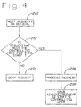
- Fig. 4 is a flow chart of the preferred method of processing an out-dial calling request initiated from a host computer; and
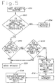
- Fig. 5 is a flow chart of the preferred method of processing a call transfer from a host computer.
- Referring to Fig. 1,
telecommunication system 10 is shown with an automatic call distributor (ACD) 12 having amultiport switch 14 operating under the control of a centralcontrol processing unit 16 in conjunction withmain memory 18 for selectively interconnecting telephonic calls received from externaltelephonic units 20 through external publictelephonic switches 22 of an externaltelephonic network 24 with a plurality of agenttelephonic units multiport switch 14 of thecall distributor 12. The agents stationed at the groups of internaltelephonic units 26A-D service the telephonic calls received from the externaltelephonic units 20 through themultiport switch 14 of the ACD 10. At each agent station corresponding to the internaltelephonic units 26A-D is an associateddata terminal data terminals 30A-D are coupled with an associated hostdata base computer data base computers 32A-D store customer information such as names, addresses, purchasing history, preferential treatment status, billing records and other types of data relating to callers from the external telephonic units. The plurality of hostdata base computers 32A-D are selectively provided by the user or purchaser of the telecommunication system in which is stored proprietary customer information. - The host
data base computers 32A-D are preferably placed at a location, such as a user site, remote from theautomatic call distributor 12 facility. The hostdata base computers 32A-D communicate with the centralcontrol processing unit 18 of the ACD 12 over associatedtransaction link interfaces transaction link interface 36A-D or logical link interface is coupled to a peripheral data interface (PDI)circuit 40 of theACD 12. Messaging between the centralcontrol processing unit 16 and the plurality of hostdata base computers 32A-D is over the associatedlogical link interface 36A-D via thePDI circuit 40. Thelogical link interfaces 36A-D each have a pair ofphysical link lines physical links 38A-D between thehost computers 32A-D and the ACD 12 follows an X.25 communication protocol. Messages are carried on both of the pair ofphysical links 38A-D during communication between the ACD centralcontrol processing unit 16 and thehost computer 32A-D associated with the correspondinglogical link interface 36A-D. If one of the pair ofphysical links 38A-D goes down or is disabled for a particularlogical link interface 36A-D, then all messages transmitted between the associatedhost computer 32A-D and the ACD 12 are automatically carried on the other remaining physical link. - The peripheral data
interface circuit card 40 provides the interface mechanism between the ACD centralcontrol processing unit 16 and the remote hostdata base computers 32A-D. ThePDI circuit 40 has a Motorola 68000 microprocessor for providing the overall controlling functions of the PDI circuit. ThePDI circuit 40 has a plurality of serial communication controllers (not shown) for providing serial communication over the physical links. The PDI circuit coordinates data transfers between the ACDcentral processing unit 16 and the peripheralremote host computers 32A-D. For further details of the operation of the peripheraldata interface circuit 40, reference should be made to U.S. patent application Serial No. 07/976,131 of Kovarik filed November 12, 1992 entitled "Automatic call Distributor With A Programmable Data Window Display System and Method". - The central
control processing unit 16 is the primary controller for theautomatic call distributor 12. The processing power for the centralcontrol processing unit 16 is preferably provided by a thirty-two bit Motorola 68030 microprocessor capable of either simplex or duplex operation. Generally, while the multilink host computer callcontrol interface system 25 system of the present invention can be implemented in various types and sizes of an automatic call distributors, it is preferably employed in a call distributor of the type shown in U.S. patent No. 5,268,903 of Jones et al. entitled "Multichannel Telephonic Switching Network With Different Signaling Formats and Connect/PBX Treatment Selectable For Each Channel", issued December 7, 1993; U.S. patent No. 5,140,611 of Jones et al. entitled "Pulse Modulated self-Clocking and Self-Synchronizing Data Transmission and Method for a Telephonic Communication Switching System", issued August 18, 1992; U.S. patent No. 5,127,004 of Lenihan et al. entitled "Tone and Announcement Message Code Generator for a Telephonic Switching System and Method", issued June 30, 1992 and U.S. patent No. 4,627,047 of Pitroda et al. entitled "Integrated Voice and Data Telecommunications switching System", issued December 2, 1986. - The
multiple host computers 32A-D are each connected to and selectively provide calling control functionality to theautomatic call distributor 12 over the associatedtransaction link interface 36A-D. Customer information gathered by agents at the internaltelephonic units 26A-D is entered at the associateddata terminals 30A-D for storage at the corresponding hostdata base computers 32A-D. Thehost computers 32A-D are external remote mainframe computers which are selectively provided by the purchaser or user of thetelecommunications system 10. Preferably, the host computers are any suitable minicomputer or microcomputer such as an International Business Machines (IBM) 3090, IBM AS400 or Hewlett Packard 9000 having an appropriate interface to an automatic call distributor. - The
multiple transaction links 36A-D are run-time call control interfaces connecting a singleindividual ACD 12 withmultiple host computers transaction link interface 36A-D provides each associated host computer with call and position control for a corresponding group of interiortelephonic units 26A-D. The particular hostdata base computer 32A-D associated with a defined group of internaltelephonic units 26A-D is considered the controlling host computer for that particular group. The one of the plurality of host computers assigned to be the controlling host computer sends messages toACD 12 requesting execution of various call control handling operations regarding telephonic calls associated with the internal telephonic units corresponding to the controlling hoot computer. Preferably, a selected controlling host computer is the host computer for a group of internal telephonic units which has a physical connection to the data terminals associated with the group of internal units. For example, in Fig. 1,host computer 32A is selectively determined to be the controlling host computer for internaltelephonic units groups 26A sincehost 32A has a physical connection todata terminals 30A.Host computer 30A can appropriately display information concerning calls routed to agents at the internal telephonic units ofgroup 26A at the correspondingdata terminals 30A. - The internal
telephonic units 26A-D associated with a particular controlling host computer are not limited to agent telephonic units, but rather, further include supervisory telephonic units, voice response units and other types of telephonic units coupled with themultiport switch 14. A controlling host is also selectively defined based on the type of call received at theswitch 14, the inbound trunk lines which receive a call, call identification information such as DNIS and ANI numbers, and outbound call trunk lines. Thetransaction link interface 36A-D feature Of the present invention sends each message pertaining to a particular call or group ofinternal units 26A-D to a single host data base computer with eachhost computer 32A-D connected to a pair ofphysical links 38A-D. Each of the hostdata base computers 32A-D controls and is informed about its own predetermined and defined set of internaltelephonic units 26A-D (i.e. agent units, supervisor units, voice response units, etc.) and telephonic calls. A host computer, forexample host computer 32A, identified as the one host computer which is enabled to initiate call handling requests for calls at a predefined group ofinternal unit 26A is considered thecontrolling host computer 32A for the correspondinginternal units 26A. Requests for call handling operations by other noncontrolling host computers (i.e. hosts 32B, 32C and 32D) to be performed atinternal units 26A which is controlled byhost computer 32A are denied. - Messaging across transaction link 36A allows many calling actions that are often initiated at an internal
telephonic unit 26A to be activated by the corresponding controllinghost computer 32A. For example, an individual at an internaltelephonic unit 26A selectively actuates an associateddata terminal 30A to sign-in, sign-out, initiate a call, transfer a call, and clear a call by signalling the correspondingcontrolling host 32A. Thehost 32A communicates to theACD 12 over thelogical link interface 36A without agent intervention to automate routing of calls at theswitch 14 and to provide customer data on an associateddata terminal 30A to match an incoming call distributed at a particularinternal unit 26A, called screen synchronization. - Each of the call servicing features is controlled by conversations which take place between the
ACD 12 and the identifiedhost computer 32A over the appropriatelogical link interface 36A. These conversations consist of messages, built from message elements, which are preferably initiated by the designated host computer and sent to theACD 12. TheACD 12 often responds with a message that the command completed successfully or failed due to a specific error. Communication over thephysical links 38A-D to enable a call handling operation periodically requires one or more message-response conversations between aparticular host computer 32A-D and theACD 12. - The
ACD 12 alternatively also provides unsolicited messages to the one designated controlling host computer, such as call arrival at theswitch 14 and position status changes at the associated internal units, which then allows the controlling host to initiate a feature such as call routing, call transfer, internal telephonic unit status synchronization, or screen synchronization of information at an associated data terminal. When a call related feature operation such as screen synchronisation is designated by the controlling host computer, the operation frequently requires the use of several alternative features to complete a series of conversations. If errors occur during operations, error messages are sent between the one identifiedcontrolling host computer 32A andACD 12. Error messages are either a general error message (Negative Response) containing a specific error, code, or a call servicing feature-specific error message. - The user is enabled to preselect separate segments of the
system 10 to be dedicated for a particular host computer (i.e. trunk group lines x,y,z, DNIS Q,R,S and group A of internaltelephonic units 26A are all assigned tohost computer 32A. Calls coming in on trunk group lines x,y,z or having DNIS Q,R, or S are always routed to individuals stationed at internaltelephonic units 26A). Once an initial call indication is sent to a particular host computer (e.g. call arrival message to the host computer) the call is flagged as being controlled by the host computer to which the original indication is provided. - The host computer to which the initial call indication is sent depends on the originator of the call indication and the predefined call handling routing priority pattern if one is present. If the originating indicator identifying a controlling host computer is a trunk line and the predefined routing priority pattern or telescript does either an INFORM HOST or REQUEST HOST command, the controlling host computer is based upon the last successfully translated routing operand (i.e. call identification information such as ANI and DNIS information or the particular trunk group of the trunk line receiving the call) in the predefined routing priority pattern prior to the INFORM or REQUEST HOST. If no successful translations were performed, then the default controlling host identifier is based upon the identification of the controlling host for the trunk line receiving the call. If the call arrival transmission fails (e.g. link is down), the call is still flagged as having the identified host computer as the controlling host computer for the call.
- If the originator is an incoming trunk line and no call arrival is sent via the predefined routing priority pattern, the controlling host computer is based upon the controlling host identifier of the internal telephonic unit receiving the call. If the unit is an agent unit, supervisor unit, or voice response unit, it is the host computer identified in the units class of service memory table in the
main memory 18. If the call is routed through an outbound trunk, the controlling host identifier for the trunk group of the particular outbound trunk is used. If the originator is an internal telephonic unit on theswitch 14 and it is dialed directly by an individual at the unit, then the one controlling host computer is the host computer defined in the class of service table memory for the particular internal unit. If the originator is an internal telephonic unit on theswitch 14 and it is dialing due to a request from one of the plurality ofhost computers 32A-D, the controlling host computer is the host which performed the request. Changes in status of theinternal units 26A-D are reported to the controlling host computer defined for the particular internal unit in its class of service table in themain memory 18. Predictively out-dialed calls initiated by a host computer have the requesting host computer flagged as the controlling host computer for the out-dialed call. - Preferably a call related controlling host computer takes precedence over a position (i.e. internal unit) related controlling host. For example, if a call that is defined as controlled by a given
host computer 32A is connected to an internaltelephonic unit 26B which is set to be controlled byhost computer 32B,only host computer 32A is enabled to perform call handling operations related to that call.Host computer 32B is still enabled to perform status change operations and to initiate calls for the associated internaltelephonic unit 26B. - The messaging over the
logical link interface 36A-D keeps all messages for a call directed at the identified controlling host computer, enables only the controlling host to send any call related requests, returns responses to the requesting host computer and sends all noncall-related messages to the assigned host computer for a particular internal telephonic unit. - Referring now to Figs. 2A-2C, the control for a received incoming call begins at step 100, Fig. 2A, with a telephonic call arriving on a port at the
multiport switch 14. In step 102, the automatic call distributor (ACD) 12 determines if the received call is an external telephonic call from the externaltelephonic network 24 or an internal call received from an internaltelephonic unit 26A-D or ahost computer 32A-D coupled with theACD 12. If the call originated from an internaltelephonic unit 26A-D orhost computer 32A-D at the telecommunication system, then step 134, Fig. 2C, is the next step in the process. If the received call originates outside the telecommunication system 10 (i.e. from the external network 24), then instep 104, theACD 12 checks if the host computer will be informed of the call or if the ACD requests the host computer to provide routing instructions regarding the call. - If the
ACD 12 will inform a host computer of the received call or will request a route from the host computer for the call, then instep 106, the ACD determines if a successful translation of the routing operand based on information received from the external network 24 (i.e. ANI or DNIS) or the trunk group assignment has occurred. If the routing operand translation is not successful, then in step 108central processing unit 16 of theACD 12 determines if a controlling host computer is defined for the particular trunk of a trunk group at which the call was received. If a controlling host computer is assigned to the trunk line on which the call was received, then in step 110 a call arrival message is sent to the corresponding controlling host computer based on the trunk group of the received call. In step 112 a controlling host flag is set in a call store table in the ACDmain memory 18 for the received call based on the assignment of a controlling host computer indicated by the trunk group of the received call. - If the translation of the routing operand was successful in
step 106, then instep 114 theACD 12 sends a call arrival message to the one particular host computer identified in the defined routing operand. Instep 116, the controlling host flag is set for the received call based on the predetermined routing operand. Instep 118, Fig. 2B, theACD 12 determines if the call is to be outbound routed through a dialing plan identifying an offnet number to the externaltelephonic network 24. If the call is an outbound routed call then instep 120, a flag is set based on the identified controlling host computer for the associated trunk group of the outbound trunk of the outbound routed call. Instep 132, processing of the call is continued. If the call is not an outbound routed call, then instep 122, Fig. 2B, the call is offered to the appropriate agent or staff personnel at an internaltelephonic unit 26A-D to service the call. Instep 124, the appropriate staff individual answers the received call at an internaltelephonic unit 26A-D. Instep 126, the ACD centralcontrol processing unit 16 determines if the controlling host computer flag is set. If the controlling host computer flag is not set then instep 128, the flag is set based on the controlling host computer identification number associated with the staff individual who is assigned to answer the routed call at an internaltelephonic unit 26A-D. If the controlling host flag is set then there is no need to identify a controlling host computer instep 130, and call processing of the call continues instep 132. - If in step 102, of Fig. 2A, the
ACD 12 determines that the received call is an internally originated call, either from an internal telephonic unit or an out-dial request from a host computer, then instep 134, Fig. 2C, theACD 12 determines if the internal call originated from an internaltelephonic unit 26A-D or ahost computer 32A-D. If the internal call was initiated by ahost computer 32A-D, then in step 136 a controlling host flag is set for the particular host computer which initiated the internal call. If the internal call was initiated at an internaltelephonic unit 26A-D, then instep 138, Fig. 2C, a controlling host flag is set for the call based on the predetermined class of service assignment for the individual staff personnel stationed at the internal telephonic unit which initiated the call. Instep 140, theACD 12 determines if the call is to be outbound routed to the externaltelephonic network 24. If the call is outbound routed then instep 142, Fig. 2C, call handling processing is maintained for the call. If the call is not outbound routed, then instep 146 the call is offered or routed to the appropriated staff individual at the corresponding internal telephonic unit. Instep 148 the individual staff personnel answers the call and processing returns to step 126 of Fig. 2B, to determine if a controlling host computer flag is set for the received call. - Referring now to Fig. 3, the procedural processing flow for a call handling operation action requested by a
host computer 32A-D begins atstep 170 in which a host computer requests theACD 12 to perform an action on a call. Instep 172, the ACDcentral processing unit 16 determines if the requesting host computer is the controlling host computer for this call by comparing the host identification information in the request message with the host identification information associated with the call. If the requesting host computer is not the controlling host computer, then instep 174 the request for a particular action regarding the call is denied. If the requesting host computer is the controlling host computer, then instep 176 the particular requested action begins processing by the centralcontrol processing unit 16. Instep 178, an acknowledgement message is sent by theACD 12 over the appropriate logical link interface to the one controlling host computer for that call. Instep 180, theACD 12 determines if the request for action by the controlling host computer caused a change in the state of the individual staff person servicing the call at an internal telephonic unit. The call servicing states for an individual at an internal unit include available, unavailable, signed-in, signed-out, call work state, etc. No action is taken instep 182 if the state of the staff member servicing the call did not change as a result of the controlling host computer request. If the action request by the controlling host computer does change the state of the associated staff individual, then instep 184, Fig. 3, an internal telephonic unit position status change message is sent to the controlling host computer for the individual staff personnel member servicing the call at the corresponding internal unit. - Referring now to Fig. 4, the procedural processing flow for an out-dial request by a host computer begin at
step 200 whereby a host computer sends a request to theACD 12 for an out-dial call. Instep 202, theACD 12 determines if the requesting host computer is the controlling host computer associated with the individual staff personnel member of an internal unit servicing the call requested to be out-dialed by reading the class of service table memory for the individual staff member. If the requesting host computer is not the controlling host computer then the request for an out-dial call by the requesting host computer is denied instep 204. If the requesting host computer is the controlling host computer for the internal telephonic unit receiving a connected out-dial call, then instep 206 the request for the out-dial call is processed. Instep 208 an acknowledgement of the out-dial request is sent to the controlling host computer corresponding to the individual staff member stationed at an internal telephonic unit which services the out-dialed call. - Referring now to Fig. 5, the process for a host computer initiated call transfer begins at step 220, in which a host computer requests a call transfer. In
step 222, theACD 12 determines if the requesting host computer is the controlling host computer of the two calls to be transferred together. If the requesting host computer is the controlling host computer of the two calls to be transferred, then instep 224 the request for call transfer is processed. If the requesting host is not the controlling host for both calls then instep 226, then theACD 12 determines if a controlling host computer flag is set for only one of the calls. If the controlling host flag is set for both calls, then instep 228 the request for call transfer is denied since the requesting host computer is not the controlling host computer of both calls. If a controlling host computer flags is set for only one of the calls, then instep 230 the ACDcentral processing unit 16 determines if the controlling host computer for that call is the one host computer requesting the call transfer. If the controlling host computer for the call is not the requesting host computer, then instep 228 the request for call transfer is denied. If the controlling host computer for the call is the requesting host computer, then instep 232 theACD 12 sets the controlling host flags for both calls to identify it as the requesting host computer. Instep 234, the request for call transfer is processed. Instep 236, theACD 12 sends an acknowledgement message to the controlling host computer (i.e. requesting host computer) indicating that the request for call transfer has been accepted and is being processed. - While a detailed description of the preferred embodiment of the invention has been given, it should be appreciated that many variations can be made thereto without departing from the scope of the invention as set forth in the appended claims.
Claims (20)
- In a telecommunication system having a single automatic call distributor with a multiport switch controlled by a central control processing unit and an associated memory for selectively interconnecting telephonic calls between external telephonic units of an external telephonic network and internal telephonic units coupled with the multiport switch, the improvement being a multilink host computer call control interface system, comprising:
a plurality of host computers coupled to the automatic call distributor; and
means for enabling communication between the single automatic call distributor and the plurality of host computers to provide the plurality of host computers with control of call handling operations performed at the automatic call distributor. - The telecommunication system of claim 1 in which the communication enabling means includes a plurality of logical link interfaces corresponding to each of the plurality of host computers for connecting the automatic call distributor to the plurality of host computers.
- The telecommunication system of claim 2 in which the plurality of logical link interfaces includes a pair of physical link lines for carrying messages between the automatic call distributor and the plurality of host computers.
- The telecommunication system of claim 3 including means for automatically sending all messages between the automatic call distributor and one of the plurality of host computers corresponding to one of the logical link interfaces across one of the pair of physical links of the one logical link interface in response to the other of the pair of physical links becoming disabled.
- The telecommunication system of claim 1 including means for designating one of the plurality of host computers as a controlling host computer for controlling call handling operations for a preselected associated group of internal telephonic units.
- The telecommunication system of claim 5 including means for initiating a request for an action on a telephonic call at the automatic call distributor by one of the plurality of host computers,
means for determining if the request initiating means is initiated from the controlling host computer, and
means for denying the action request if the host computer initiating the request is not the controlling host computer. - The telecommunication system of claim 5 in which the designating means includes
means initiated at one of the plurality of host computers for requesting execution of an out-dial call at the automatic call distributor, and
means responsive to the out-dial call requesting means for appointing the one host computer requesting the out-dial call execution as the controlling host computer for the out-dial call. - The telecommunication system of claim 1 including means for associating one of the plurality of host computers to a preselected group of internal telephonic units, and
means for identifying the one host computer as the controlling host computer for the preselected group of internal telephonic units. - The telecommunication system of claim 8 including
means for transmitting from the automatic call distributor to the controlling host computer associated with the internal units messages related to events occurring at the group of units, and
means at the controlling host computer responsive to the messages transmitting means for initiating the automatic call distributor to perform operations at the internal telephonic units. - The telecommunication system of claim 9 in which said call handling operations include at least one of(a) sign-in of internal telephonic units(b) sign-out of internal telephonic units(c) initiation of an out-dial call for connection at an internal telephonic unit(d) call transfer and(e) call clearing.
- The telecommunication system of claim 1 including means for assigning to a telephonic call received at the multiport switch a controlling host computer from one of the plurality of host computers coupled with the call distributor to initiate the control of call handling operations associated with the received telephonic call.
- The telecommunication system of claim 11 in which the assigning means includes means for identifying the one host computer as the controlling host computer based on at least one of(a) identification of a trunk group at the multiport switch on which the telephonic call is received(b) call type identification information carried with the received telephonic call(c) a predefined routing priority pattern for the received call, and(d) a controlling host identifier associated with an internal telephonic unit connected with the received call.
- The telecommunication system of claim 11 in which said call handling operations associated with the received call include at least one of(a) routing the call to an internal telephonic unit specified by the controlling host computer(b) displaying information relating to the telephonic call at a data terminal associated with an internal telephonic unit servicing the call, and(c) transferring the telephonic call.
- The telecommunication system of claim 11 including means for designating another host computer other than the one host computer associated with the received call to a preselected internal telephonic unit to initiate control of call handling actions at the internal telephonic unit associated with the other host computer, and
means for routing the received call controlled by the one host computer to the internal telephonic unit controlled by the other host computer,
means for assigning call control priority to the one host computer associated with the received call over the other host computer associated with the internal telephonic unit in response to the call routing means. - In a telecommunication system having a single automatic call distributor with a multiport switch controlled by a central control processing unit and an associated memory for selectively interconnecting telephonic calls between external telephonic units of an external telephonic network and internal telephonic units coupled with the multiport switch, the improvement being a method of initiating multiple host computer call control, comprising the steps of:
coupling a plurality of host computers to the single automatic call distributor; and
enabling communication between the single automatic call distributor and the plurality of host computers to provide the plurality of host computers with control of call handling operations performed at the automatic call distributor. - The method of claim 15 including the step of designating one of the plurality of host computers as a controlling host computer for controlling call handling operations for a preselected associated group of internal telephonic units.
- The method of claim 16 including the steps of
initiating a request for an action on a telephonic call at the automatic call distributor by one of the plurality of host computers,
determining if the request for initiating an action on the telephonic call is from the controlling host computer, and
denying the action request if the host computer initiating the request is not the controlling host computer. - The method of claim 15 including the step of assigning to a telephonic call received at the multiport switch a controlling host computer from one of the plurality of host computers coupled with the call distributor to initiate the control of call handling operations associated with the received telephonic call.
- The method of claim 18 including the step of identifying the one host computer as the controlling host computer based on at least one of(a) identification of a trunk group at the multiport switch on which the telephonic call is received,(b) call type identification information carried with the received telephonic call,(c) a predefined routing priority pattern for the received call, and(d) a controlling host identifier associated with an internal telephonic unit connected with the received call.
- The method of claim 18 in which said call handling operations associated with the received call include at least one of the steps of(a) routing the call to an internal telephonic unit specified by the controlling host computer,(b) displaying information relating to the telephonic call at a data terminal associated with an internal telephonic unit servicing the call, and(c) transferring the telephonic call.
Applications Claiming Priority (2)
| Application Number | Priority Date | Filing Date | Title |
|---|---|---|---|
| US316695 | 1994-09-30 | ||
| US08/316,695 US5500891A (en) | 1994-09-30 | 1994-09-30 | Telecommunication system with multilink host computer call control interface system and method |
Publications (3)
| Publication Number | Publication Date |
|---|---|
| EP0705017A2 true EP0705017A2 (en) | 1996-04-03 |
| EP0705017A3 EP0705017A3 (en) | 1999-10-06 |
| EP0705017B1 EP0705017B1 (en) | 2004-03-31 |
Family
ID=23230236
Family Applications (1)
| Application Number | Title | Priority Date | Filing Date |
|---|---|---|---|
| EP95115418A Expired - Lifetime EP0705017B1 (en) | 1994-09-30 | 1995-09-29 | Telecommunication system with multilink host computer call control interface system and method |
Country Status (4)
| Country | Link |
|---|---|
| US (1) | US5500891A (en) |
| EP (1) | EP0705017B1 (en) |
| DE (1) | DE69532788D1 (en) |
| GB (1) | GB2293722B (en) |
Cited By (16)
| Publication number | Priority date | Publication date | Assignee | Title |
|---|---|---|---|---|
| EP0954922A1 (en) * | 1997-01-21 | 1999-11-10 | Genesys Telecommunications Laboratories, Inc. | Method and system for determining and using multiple object states in a computer telephony integration system |
| EP1011251A2 (en) * | 1998-12-17 | 2000-06-21 | Siemens Aktiengesellschaft | Method for error checking and evaluation of messages by members of an operator service and corresponding equipped switch |
| DE10059188A1 (en) * | 2000-11-29 | 2002-06-13 | Tenovis Gmbh & Co Kg | Method for routing a phone call and a record in a call center |
| KR100354807B1 (en) * | 2000-05-16 | 2002-10-05 | 주식회사 한국밴통신 | A telegate, a computer telephony integration system based on the telegate and methods for processing incoming call and outgoing call by using the telegate |
| KR100562140B1 (en) * | 1999-11-02 | 2006-03-21 | 주식회사 케이티 | Method for transmitting signal through channel conversion |
| US8971216B2 (en) | 1998-09-11 | 2015-03-03 | Alcatel Lucent | Method for routing transactions between internal and external partners in a communication center |
| US9002920B2 (en) | 1998-09-11 | 2015-04-07 | Genesys Telecommunications Laboratories, Inc. | Method and apparatus for extended management of state and interaction of a remote knowledge worker from a contact center |
| US9008075B2 (en) | 2005-12-22 | 2015-04-14 | Genesys Telecommunications Laboratories, Inc. | System and methods for improving interaction routing performance |
| USRE45583E1 (en) | 1999-12-01 | 2015-06-23 | Genesys Telecommunications Laboratories, Inc. | Method and apparatus for providing enhanced communication capability for mobile devices on a virtual private network |
| USRE45606E1 (en) | 1997-02-10 | 2015-07-07 | Genesys Telecommunications Laboratories, Inc. | Call and data correspondence in a call-in center employing virtual restructuring for computer telephony integrated functionality |
| USRE46060E1 (en) | 1997-02-10 | 2016-07-05 | Genesys Telecommunications Laboratories, Inc. | In-band signaling for routing |
| USRE46153E1 (en) | 1998-09-11 | 2016-09-20 | Genesys Telecommunications Laboratories, Inc. | Method and apparatus enabling voice-based management of state and interaction of a remote knowledge worker in a contact center environment |
| US9516171B2 (en) | 1997-02-10 | 2016-12-06 | Genesys Telecommunications Laboratories, Inc. | Personal desktop router |
| US9553755B2 (en) | 1998-02-17 | 2017-01-24 | Genesys Telecommunications Laboratories, Inc. | Method for implementing and executing communication center routing strategies represented in extensible markup language |
| USRE46438E1 (en) | 1999-09-24 | 2017-06-13 | Genesys Telecommunications Laboratories, Inc. | Method and apparatus for data-linking a mobile knowledge worker to home communication-center infrastructure |
| USRE46528E1 (en) | 1997-11-14 | 2017-08-29 | Genesys Telecommunications Laboratories, Inc. | Implementation of call-center outbound dialing capability at a telephony network level |
Families Citing this family (28)
| Publication number | Priority date | Publication date | Assignee | Title |
|---|---|---|---|---|
| US5790650A (en) * | 1994-06-01 | 1998-08-04 | Davox Corporation | Telephone call center management system which supports multi-user and separate private applications |
| US5784452A (en) * | 1994-06-01 | 1998-07-21 | Davox Corporation | Telephony call center with agent work groups |
| US5696818A (en) * | 1995-09-13 | 1997-12-09 | Rockwell International Corp. | Delay announcement group and time controller for a telephone system |
| US5884032A (en) | 1995-09-25 | 1999-03-16 | The New Brunswick Telephone Company, Limited | System for coordinating communications via customer contact channel changing system using call centre for setting up the call between customer and an available help agent |
| US5802163A (en) * | 1996-04-05 | 1998-09-01 | Genesys Telccommunications Laboratories, Inc. | Methods and apparatus for implementing an outbound network call center |
| US5825870A (en) * | 1996-04-05 | 1998-10-20 | Genesys Telecommunications Laboratories | Methods and apparatus for implementing a network call center |
| US6091808A (en) * | 1996-10-17 | 2000-07-18 | Nortel Networks Corporation | Methods of and apparatus for providing telephone call control and information |
| US6111947A (en) * | 1996-12-02 | 2000-08-29 | Mci Communications Corporation | Intelligent services network adjunct processor |
| US5907611A (en) * | 1997-04-11 | 1999-05-25 | Rockwell International Corp. | Apparatus and method for identifying records of overflowed ACD calls |
| US5910983A (en) * | 1997-05-19 | 1999-06-08 | Rockwell Semiconductor Systems, Inc. | Apparatus and method for identifying records of overflowed ACD calls |
| US5901215A (en) | 1997-05-20 | 1999-05-04 | Rockwell Semiconductor Systems, Inc. | Apparatus and method for identifying records of overflowed ACD calls |
| US5933828A (en) * | 1997-06-16 | 1999-08-03 | Eitel; Robert T. | Method of structuring a database of a control system for access by third party software |
| US6038308A (en) * | 1997-11-11 | 2000-03-14 | Rockwell Semiconductor Systems, Inc. | ISDN primary rate interswitch mail using non-call associated temporary signalling |
| US6044145A (en) * | 1998-01-19 | 2000-03-28 | Rockwell Semiconductor Systems, Inc. | Telecommutable platform |
| US6934277B1 (en) | 1998-02-26 | 2005-08-23 | Rockwell Electronic Commerce Technologies, Llc | Internet web site with audio interconnect and automatic call distributor |
| US6209051B1 (en) * | 1998-05-14 | 2001-03-27 | Motorola, Inc. | Method for switching between multiple system hosts |
| US6449356B1 (en) | 1998-05-26 | 2002-09-10 | Rockwell Semiconductor Systems, Inc. | Method of multi-media transaction processing |
| JP3471226B2 (en) * | 1998-07-01 | 2003-12-02 | 富士通株式会社 | User equipment for distributed networks |
| US6289373B1 (en) | 1998-08-24 | 2001-09-11 | Rockwell Electronic Commerce Corp. | Method of processing E-mail in an automatic call distributor |
| US7092509B1 (en) | 1999-09-21 | 2006-08-15 | Microlog Corporation | Contact center system capable of handling multiple media types of contacts and method for using the same |
| US6775378B1 (en) | 1999-10-25 | 2004-08-10 | Concerto Software, Inc | Blended agent contact center |
| US6832203B1 (en) | 1999-11-05 | 2004-12-14 | Cim, Ltd. | Skills based contact routing |
| US7230927B1 (en) | 1999-12-07 | 2007-06-12 | Aspect Software, Inc. | Non-blocking expandable call center architecture |
| US6707906B1 (en) | 2000-03-13 | 2004-03-16 | Concerto Software, Inc. | Outbound calling system in a contact center |
| US6701322B1 (en) | 2000-06-07 | 2004-03-02 | Ge Financial Assurance Holdings, Inc. | Interactive customer-business interview system and process for managing interview flow |
| US6766011B1 (en) | 2000-06-16 | 2004-07-20 | Concerto Software, Inc. | Method and apparatus for controlling a contact center |
| US6778951B1 (en) | 2000-08-09 | 2004-08-17 | Concerto Software, Inc. | Information retrieval method with natural language interface |
| US6778660B2 (en) | 2001-04-06 | 2004-08-17 | Concerto Software, Inc. | Customer interaction system |
Citations (4)
| Publication number | Priority date | Publication date | Assignee | Title |
|---|---|---|---|---|
| US4627047A (en) | 1982-01-07 | 1986-12-02 | Rockwell International Corp. | Integrated voice and data telecommunication switching system |
| US5127004A (en) | 1989-09-15 | 1992-06-30 | Rockwell International Corporation | Tone and announcement message code generator for a telephonic switching system and method |
| US5140611A (en) | 1989-09-29 | 1992-08-18 | Rockwell International Corporation | Pulse width modulated self-clocking and self-synchronizing data transmission and method for a telephonic communication network switching system |
| US5268903A (en) | 1991-10-02 | 1993-12-07 | Rockwell International Corporation | Multichannel telephonic switching network with different signaling formats and cross connect/PBX treatment selectable for each channel |
Family Cites Families (5)
| Publication number | Priority date | Publication date | Assignee | Title |
|---|---|---|---|---|
| US5153909A (en) * | 1989-05-25 | 1992-10-06 | At&T Bell Laboratories | Resource control and data handling for central office based automatic call distributors |
| US5001710A (en) * | 1989-10-24 | 1991-03-19 | At&T Bell Laboratories | Customer programmable automated integrated voice/data technique for communication systems |
| ES2134763T3 (en) * | 1990-08-09 | 1999-10-16 | Rolm Systems | DIALING OF CALLS WITH USER INFORMATION IN A TELEPHONE FIELD. |
| US5181239A (en) * | 1990-08-09 | 1993-01-19 | Rolm Systems | Call tagging user information in a telephonic environment |
| WO1994000945A1 (en) * | 1992-06-25 | 1994-01-06 | Teledata Solutions, Inc. | Call distributor |
-
1994
- 1994-09-30 US US08/316,695 patent/US5500891A/en not_active Expired - Lifetime
-
1995
- 1995-09-29 GB GB9519940A patent/GB2293722B/en not_active Expired - Fee Related
- 1995-09-29 EP EP95115418A patent/EP0705017B1/en not_active Expired - Lifetime
- 1995-09-29 DE DE69532788T patent/DE69532788D1/en not_active Expired - Lifetime
Patent Citations (4)
| Publication number | Priority date | Publication date | Assignee | Title |
|---|---|---|---|---|
| US4627047A (en) | 1982-01-07 | 1986-12-02 | Rockwell International Corp. | Integrated voice and data telecommunication switching system |
| US5127004A (en) | 1989-09-15 | 1992-06-30 | Rockwell International Corporation | Tone and announcement message code generator for a telephonic switching system and method |
| US5140611A (en) | 1989-09-29 | 1992-08-18 | Rockwell International Corporation | Pulse width modulated self-clocking and self-synchronizing data transmission and method for a telephonic communication network switching system |
| US5268903A (en) | 1991-10-02 | 1993-12-07 | Rockwell International Corporation | Multichannel telephonic switching network with different signaling formats and cross connect/PBX treatment selectable for each channel |
Cited By (26)
| Publication number | Priority date | Publication date | Assignee | Title |
|---|---|---|---|---|
| EP0954922A4 (en) * | 1997-01-21 | 2002-05-29 | Genesys Telecomm Lab Inc | Method and system for determining and using multiple object states in a computer telephony integration system |
| EP0954922A1 (en) * | 1997-01-21 | 1999-11-10 | Genesys Telecommunications Laboratories, Inc. | Method and system for determining and using multiple object states in a computer telephony integration system |
| USRE45606E1 (en) | 1997-02-10 | 2015-07-07 | Genesys Telecommunications Laboratories, Inc. | Call and data correspondence in a call-in center employing virtual restructuring for computer telephony integrated functionality |
| USRE46243E1 (en) | 1997-02-10 | 2016-12-20 | Genesys Telecommunications Laboratories, Inc. | In-band signaling for routing |
| US9516171B2 (en) | 1997-02-10 | 2016-12-06 | Genesys Telecommunications Laboratories, Inc. | Personal desktop router |
| USRE46060E1 (en) | 1997-02-10 | 2016-07-05 | Genesys Telecommunications Laboratories, Inc. | In-band signaling for routing |
| USRE46521E1 (en) | 1997-09-30 | 2017-08-22 | Genesys Telecommunications Laboratories, Inc. | Method and apparatus for extended management of state and interaction of a remote knowledge worker from a contact center |
| USRE46528E1 (en) | 1997-11-14 | 2017-08-29 | Genesys Telecommunications Laboratories, Inc. | Implementation of call-center outbound dialing capability at a telephony network level |
| US9553755B2 (en) | 1998-02-17 | 2017-01-24 | Genesys Telecommunications Laboratories, Inc. | Method for implementing and executing communication center routing strategies represented in extensible markup language |
| USRE46387E1 (en) | 1998-09-11 | 2017-05-02 | Genesys Telecommunications Laboratories, Inc. | Method and apparatus for extended management of state and interaction of a remote knowledge worker from a contact center |
| US8971216B2 (en) | 1998-09-11 | 2015-03-03 | Alcatel Lucent | Method for routing transactions between internal and external partners in a communication center |
| US10218848B2 (en) | 1998-09-11 | 2019-02-26 | Genesys Telecommunications Laboratories, Inc. | Method and apparatus for extended management of state and interaction of a remote knowledge worker from a contact center |
| US9350808B2 (en) | 1998-09-11 | 2016-05-24 | Alcatel Lucent | Method for routing transactions between internal and external partners in a communication center |
| US9002920B2 (en) | 1998-09-11 | 2015-04-07 | Genesys Telecommunications Laboratories, Inc. | Method and apparatus for extended management of state and interaction of a remote knowledge worker from a contact center |
| USRE46153E1 (en) | 1998-09-11 | 2016-09-20 | Genesys Telecommunications Laboratories, Inc. | Method and apparatus enabling voice-based management of state and interaction of a remote knowledge worker in a contact center environment |
| EP1011251A2 (en) * | 1998-12-17 | 2000-06-21 | Siemens Aktiengesellschaft | Method for error checking and evaluation of messages by members of an operator service and corresponding equipped switch |
| EP1011251A3 (en) * | 1998-12-17 | 2004-01-28 | Siemens Aktiengesellschaft | Method for error checking and evaluation of messages by members of an operator service and corresponding equipped switch |
| USRE46438E1 (en) | 1999-09-24 | 2017-06-13 | Genesys Telecommunications Laboratories, Inc. | Method and apparatus for data-linking a mobile knowledge worker to home communication-center infrastructure |
| USRE46457E1 (en) | 1999-09-24 | 2017-06-27 | Genesys Telecommunications Laboratories, Inc. | Method and apparatus for data-linking a mobile knowledge worker to home communication-center infrastructure |
| KR100562140B1 (en) * | 1999-11-02 | 2006-03-21 | 주식회사 케이티 | Method for transmitting signal through channel conversion |
| USRE45583E1 (en) | 1999-12-01 | 2015-06-23 | Genesys Telecommunications Laboratories, Inc. | Method and apparatus for providing enhanced communication capability for mobile devices on a virtual private network |
| KR100354807B1 (en) * | 2000-05-16 | 2002-10-05 | 주식회사 한국밴통신 | A telegate, a computer telephony integration system based on the telegate and methods for processing incoming call and outgoing call by using the telegate |
| DE10059188A1 (en) * | 2000-11-29 | 2002-06-13 | Tenovis Gmbh & Co Kg | Method for routing a phone call and a record in a call center |
| USRE46538E1 (en) | 2002-10-10 | 2017-09-05 | Genesys Telecommunications Laboratories, Inc. | Method and apparatus for extended management of state and interaction of a remote knowledge worker from a contact center |
| US9854006B2 (en) | 2005-12-22 | 2017-12-26 | Genesys Telecommunications Laboratories, Inc. | System and methods for improving interaction routing performance |
| US9008075B2 (en) | 2005-12-22 | 2015-04-14 | Genesys Telecommunications Laboratories, Inc. | System and methods for improving interaction routing performance |
Also Published As
| Publication number | Publication date |
|---|---|
| US5500891A (en) | 1996-03-19 |
| EP0705017A3 (en) | 1999-10-06 |
| GB2293722B (en) | 1999-03-03 |
| DE69532788D1 (en) | 2004-05-06 |
| EP0705017B1 (en) | 2004-03-31 |
| GB2293722A (en) | 1996-04-03 |
| GB9519940D0 (en) | 1995-11-29 |
Similar Documents
| Publication | Publication Date | Title |
|---|---|---|
| US5500891A (en) | Telecommunication system with multilink host computer call control interface system and method | |
| US4975945A (en) | Universal telephone call relay system | |
| EP0425163B1 (en) | Customer programmable automated integrated voice/data technique for communication systems | |
| KR100359586B1 (en) | Automatic call distribution method and apparatus | |
| EP0821510B1 (en) | Telecommunications routing apparatus and method | |
| US5778060A (en) | Work at home ACD agent network with cooperative control | |
| US5046088A (en) | Converter for in-band routing and/or origination information | |
| US5008930A (en) | Customer definable integrated voice/data call transfer technique | |
| US5452348A (en) | Automatic call distribution system with emergency conferencing and method | |
| JPH0723111A (en) | Personal communication service supply system | |
| US4486626A (en) | Method of and system for limiting access to a group of telephone trunks | |
| KR19990029551A (en) | Call processing system and method | |
| US6453039B1 (en) | Method and apparatus for robust call routing | |
| US5315647A (en) | Private branch exchange adapted for telemarketing | |
| EP0793374B1 (en) | Video switching system video communications system and method for automatically establishing video communications using a telephonic switch | |
| EP0674418A2 (en) | Automatic call distributor with telephonic call holding system | |
| US4560837A (en) | Call transfer method and circuitry | |
| US5864615A (en) | Audio communications inferface, method and communications system for connecting a remote agent to a telephone switch | |
| EP0534783B1 (en) | Key telephone system with virtual private lines | |
| JPH0646156A (en) | Method and apparatus for transfer of telecommunication customer | |
| JP2847039B2 (en) | Incoming call notification system and information processing system used therefor | |
| US6181366B1 (en) | Video switching system, video communications system and method for establishing video communications with a telephonic switch | |
| EP0912033B1 (en) | Call transfer in an automatic call distributor | |
| US6501839B1 (en) | Method and apparatus for equitable call delivery | |
| EP0792559B1 (en) | Procedure and system for processing data traffic signals carrying information |
Legal Events
| Date | Code | Title | Description |
|---|---|---|---|
| PUAI | Public reference made under article 153(3) epc to a published international application that has entered the european phase |
Free format text: ORIGINAL CODE: 0009012 |
|
| AK | Designated contracting states |
Kind code of ref document: A2 Designated state(s): DE FR GB NL |
|
| PUAL | Search report despatched |
Free format text: ORIGINAL CODE: 0009013 |
|
| AK | Designated contracting states |
Kind code of ref document: A3 Designated state(s): DE |
|
| 17P | Request for examination filed |
Effective date: 19991117 |
|
| RBV | Designated contracting states (corrected) |
Designated state(s): DE FR GB NL |
|
| 17Q | First examination report despatched |
Effective date: 20020723 |
|
| GRAP | Despatch of communication of intention to grant a patent |
Free format text: ORIGINAL CODE: EPIDOSNIGR1 |
|
| GRAS | Grant fee paid |
Free format text: ORIGINAL CODE: EPIDOSNIGR3 |
|
| GRAA | (expected) grant |
Free format text: ORIGINAL CODE: 0009210 |
|
| AK | Designated contracting states |
Kind code of ref document: B1 Designated state(s): DE FR GB NL |
|
| PG25 | Lapsed in a contracting state [announced via postgrant information from national office to epo] |
Ref country code: NL Free format text: LAPSE BECAUSE OF FAILURE TO SUBMIT A TRANSLATION OF THE DESCRIPTION OR TO PAY THE FEE WITHIN THE PRESCRIBED TIME-LIMIT Effective date: 20040331 Ref country code: FR Free format text: LAPSE BECAUSE OF FAILURE TO SUBMIT A TRANSLATION OF THE DESCRIPTION OR TO PAY THE FEE WITHIN THE PRESCRIBED TIME-LIMIT Effective date: 20040331 |
|
| REG | Reference to a national code |
Ref country code: GB Ref legal event code: FG4D |
|
| REF | Corresponds to: |
Ref document number: 69532788 Country of ref document: DE Date of ref document: 20040506 Kind code of ref document: P |
|
| PG25 | Lapsed in a contracting state [announced via postgrant information from national office to epo] |
Ref country code: DE Free format text: LAPSE BECAUSE OF FAILURE TO SUBMIT A TRANSLATION OF THE DESCRIPTION OR TO PAY THE FEE WITHIN THE PRESCRIBED TIME-LIMIT Effective date: 20040701 |
|
| NLV1 | Nl: lapsed or annulled due to failure to fulfill the requirements of art. 29p and 29m of the patents act | ||
| REG | Reference to a national code |
Ref country code: GB Ref legal event code: 732E |
|
| PLBE | No opposition filed within time limit |
Free format text: ORIGINAL CODE: 0009261 |
|
| STAA | Information on the status of an ep patent application or granted ep patent |
Free format text: STATUS: NO OPPOSITION FILED WITHIN TIME LIMIT |
|
| EN | Fr: translation not filed | ||
| 26N | No opposition filed |
Effective date: 20050104 |
|
| REG | Reference to a national code |
Ref country code: GB Ref legal event code: 732E |
|
| PGFP | Annual fee paid to national office [announced via postgrant information from national office to epo] |
Ref country code: GB Payment date: 20080929 Year of fee payment: 14 |
|
| GBPC | Gb: european patent ceased through non-payment of renewal fee |
Effective date: 20090929 |
|
| PG25 | Lapsed in a contracting state [announced via postgrant information from national office to epo] |
Ref country code: GB Free format text: LAPSE BECAUSE OF NON-PAYMENT OF DUE FEES Effective date: 20090929 |