EP0703797B1 - Syringe for infusion - Google Patents
Syringe for infusion Download PDFInfo
- Publication number
- EP0703797B1 EP0703797B1 EP94916106A EP94916106A EP0703797B1 EP 0703797 B1 EP0703797 B1 EP 0703797B1 EP 94916106 A EP94916106 A EP 94916106A EP 94916106 A EP94916106 A EP 94916106A EP 0703797 B1 EP0703797 B1 EP 0703797B1
- Authority
- EP
- European Patent Office
- Prior art keywords
- syringe
- piston
- actuator
- rear part
- passageway
- Prior art date
- Legal status (The legal status is an assumption and is not a legal conclusion. Google has not performed a legal analysis and makes no representation as to the accuracy of the status listed.)
- Expired - Lifetime
Links
Images
Classifications
-
- A—HUMAN NECESSITIES
- A61—MEDICAL OR VETERINARY SCIENCE; HYGIENE
- A61M—DEVICES FOR INTRODUCING MEDIA INTO, OR ONTO, THE BODY; DEVICES FOR TRANSDUCING BODY MEDIA OR FOR TAKING MEDIA FROM THE BODY; DEVICES FOR PRODUCING OR ENDING SLEEP OR STUPOR
- A61M5/00—Devices for bringing media into the body in a subcutaneous, intra-vascular or intramuscular way; Accessories therefor, e.g. filling or cleaning devices, arm-rests
- A61M5/14—Infusion devices, e.g. infusing by gravity; Blood infusion; Accessories therefor
- A61M5/142—Pressure infusion, e.g. using pumps
- A61M5/145—Pressure infusion, e.g. using pumps using pressurised reservoirs, e.g. pressurised by means of pistons
- A61M5/155—Pressure infusion, e.g. using pumps using pressurised reservoirs, e.g. pressurised by means of pistons pressurised by gas introduced into the reservoir
-
- A—HUMAN NECESSITIES
- A61—MEDICAL OR VETERINARY SCIENCE; HYGIENE
- A61M—DEVICES FOR INTRODUCING MEDIA INTO, OR ONTO, THE BODY; DEVICES FOR TRANSDUCING BODY MEDIA OR FOR TAKING MEDIA FROM THE BODY; DEVICES FOR PRODUCING OR ENDING SLEEP OR STUPOR
- A61M5/00—Devices for bringing media into the body in a subcutaneous, intra-vascular or intramuscular way; Accessories therefor, e.g. filling or cleaning devices, arm-rests
- A61M5/14—Infusion devices, e.g. infusing by gravity; Blood infusion; Accessories therefor
- A61M5/142—Pressure infusion, e.g. using pumps
- A61M2005/14204—Pressure infusion, e.g. using pumps with gas-producing electrochemical cell
Landscapes
- Health & Medical Sciences (AREA)
- Vascular Medicine (AREA)
- Engineering & Computer Science (AREA)
- Anesthesiology (AREA)
- Biomedical Technology (AREA)
- Heart & Thoracic Surgery (AREA)
- Hematology (AREA)
- Life Sciences & Earth Sciences (AREA)
- Animal Behavior & Ethology (AREA)
- General Health & Medical Sciences (AREA)
- Public Health (AREA)
- Veterinary Medicine (AREA)
- Infusion, Injection, And Reservoir Apparatuses (AREA)
Abstract
Description
- This invention relates to syringes, particularly prefilled syringes, such as are utilized for the dispensing of pharmaceutical and personal care products.
- In the context of this invention the term "syringe" is used broadly to refer to a container, having a tubular body usually of cylindrical cross-section, and liquid contents which are dispensed through a relatively small tubulation present or introduced at one otherwise closed end, hereinafter referred to as the forward end, of the body upon displacement of piston longitudinally within the body. By "prefilled" is meant either prefilled with a liquid which is dispensed, or prefilled with a liquid soluble or miscible component of such a liquid which can be reconstituted by addition of a second liquid diluent, solvent or carrier component immediately prior to use. The body of such a syringe is usually but not necessarily of glass or synthetic plastic material, and usually but not necessarily transparent.
- It is important that the contents of a prefilled syringe be secure against leakage or contamination during storage, and in many cases during terminal sterilization which is required prior to storage. This entails that the piston makes a seal with the body which is hermetic or near hermetic. At least the peripheral walls of such pistons are usually formed of elastomeric material in compressive engagement, typically in plural longitudinally spaced annular zones, with an inside wall of the syringe body, in order to maintain the necessary seal. Despite various remedial measures which may be utilized, such as the use of silicone lubricants, this extensive engagement can give rise to significant problems when the time comes for the piston to be displaced.
- There is sufficient frictional engagement between the piston and the wall of the body that substantial force may be required to move the piston, whilst "stiction" effects mean that the force required to initiate piston movement will usually be significantly greater than that required to maintain it. Since the piston will have some longitudinal resilience, stiction effects can make it very difficult to obtain smooth discharge of the contents of syringes at low rates. These problems are often aggravated by the tendency for the piston to "seize" during storage, with the material of the piston forming a more or less tenacious bond to the wall of the body. Such seizure may require considerable force to be applied to the piston to break the bond and permit initial movement of the piston.
- When a plunger is utilized to activate the piston and expel the contents of a syringe at a fairly rapid rate, sufficient force can usually readily be applied to the piston through the plunger to overcome stiction or seizure provided that known remedial measures have been utilized, but difficulties arise when the contents of the syringe are to be dispensed slowly or in small quantities over a considerable period of time. When a pharmaceutical is to be infused slowly into a patient, available techniques include the use of syringe pumps, which incorporate an electric motor which slowly advances the piston by means of a plunger, and IV bag and minibag systems in which the pharmaceutical is discharged from the syringe into a flexible bag of fluid and is thence infused into the patient at a controlled rate. Syringe pumps are expensive and cannot always prevent irregularities of discharge due to stiction effects, particularly at very low discharge rates. Bag based systems cannot readily be set up to provide very low discharge rates and require an extra stage of preparation as well as more dilution of the pharmaceutical than may be appropriate in some cases.
- It has been proposed to provide syringes with two part pistons. In EP 0363338A, a mixing syringe utilizes pistons attached to a common plunger the front piston and the plunger having passageways which can be used in conjunction with a secondary plunger to provide a desired mixing action. In GB 2205750A, a two part piston, of which the front part is attached to a syringe plunger and has fluid non-return valves in it, is utilized to render a syringe non-refillable. In EP 0254765A, the plunger is again connected to the front part of the piston, with a space initially between the piston parts being evacuated through a one way valve in the plunger. In WO 89/00866 there is shown shown a fluid actuable syringe with tandem pistons, of which a rear piston is needle penetrable to admit fluid used to actuate a front piston.
- It is an object of the present invention to provide a syringe which addresses the problems discussed above and is better suited to applications in which the syringe contents are to be discharged at a low rate or in small quantities, whilst maintaining normal functionality. While it uses a two part piston, it does so in a manner quite different from the prior art discussed above.
- According to the invention, a syringe has a piston which is formed in two separate but normally abutting parts in longitudinal tandem within and in sealing relationship with a syringe body, namely a detached imperforate front part nearer the forward end of the body and preferably of relative smaller axial extent, and a rear part preferably of relatively greater axial extent, and formed with passageway means, which may be initially obturated, for establishing fluid communication between rear and front surfaces of that part. Only the rear part of the piston has provision for mechanical connection to a syringe actuator. A retainer ring is engaged with a rear end of the syringe body to restrain the rear part of the piston against expulsion from the syringe body. A rear surface of the front part normally abuts and is supported by a front surface of the rear part, and the two parts cooperate to provide a high degree of sealing between the piston and the body. The provision for mechanical connection to a syringe actuator provides both for connection to a mechanical actuator, and for connection with a fluid pressure actuator communicable with the passageway. By passing fluid through the passageway, from the rear to the front of the rear part, into a chamber between the two parts, the front part may be displaced forwardly relative to the rear part, thus in turn applying pressure to the syringe contents to expel the latter, but the frictional engagement between the front part and the wall of the body will be much reduced as compared with the piston as a whole, since the degree of engagement of the front part with the wall is reduced compared with the piston as a whole. "Stiction" effects are also greatly reduced, as is the force required to overcome seizing, not only because of the reduced wall engagement, but because, for material of a given hardness, the transverse flexibility of the usually disc-like front part alone will be much increased as compared to a one piece piston. Any stiction or seizing will result in pressure behind the front portion bowing the latter forward, thus reducing its engagement with the body wall and overcoming the stiction or seizing. The overall effect is to greatly reduce the pressure needed to ensure displacement of the syringe contents, whilst at the same time attaining much smoother movement even at very low displacement rates. Rearward expulsion of the rear part of the piston is present by the retainer, and the rear part thus forms a reaction surface against which the fluid pressure may act to.
- Further features of the invention are set forth in the appended claims, and will become apparent from the following description of an exemplary embodiment of the invention with reference to the accompanying drawings in which:
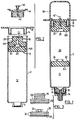
- Figure 1 is a longitudinal cross-sectional view of a syringe in accordance with the invention, during dispensing of the syringe contents by means of a gas-generator coupled to the syringe;
- Figure 2 is a similar but partially exploded view of components of a similar syringe prior to filling, together with an alternative cannula arrangement for applying fluid to operate the syringe;
- Figure 3 is a side elevational view of components of a piston of the syringe.
-
- Referring to the drawings, the syringe is based on a "bottomless vial" constructed and filled generally as described in European Published Patent Application No. 0298585. It has a generally cylindrical glass (or synthetic plastic) body 2 having a narrower neck 4 at one front or top end, and an open bottom closed by an
elastomeric piston 6. The body is filled with a pharmaceutical or personal care preparation through the neck 4, which is then closed by an elastomeric closure 8 and anannular cap 10, using conventional vial filling and capping machinery, although it should be understood that techniques utilized to fill the syringe with itscontents 12 forms no part of the present invention. The piston 4 is retained within the syringe body by aretainer ring 14 which also provides aflange 16 providing a finger grip or reaction component enabling the syringe to be actuated in a conventional manner using a plunger attached to a screw threadedextension 18 formed at the back of thepiston 6, either manually or by means of a syringe pump. The retainer ring is engaged with the syringe body in a manner somewhat similar to that described in WO 92/08507, but the details of the securement of the retainer ring do not form part of the present invention. The fitting of thering 14 does however provide a support for the piston enabling the syringe to be terminally sterilized without danger of the piston being ejected by internal pressure developed within the body. - As compared to the pistons shown in the above-mentioned European patent application, the piston in the present embodiment is axially separated into two parts, a
front part 6A nearer the forward end of the syringe body, and arear part 6B. Therear part 6B is formed with an axially extendingpassage 20, which is initially closed at its rear end by aseptum 22. Aflange 24 on a rear surface of theportion 6A enters arecess 26 on a front surface of theportion 6B to enclose an initiallysmall chamber 28, and pimples 30 on the rear surface of theportion 6A engage the front surface of theportion 6B. Both portions haveannular ridges 32 on their outer periphery which engage the inside wall of the body 2. - In order to exploit the features of the invention, the
chamber 28 is placed in communication with a source of fluid (gas or liquid) through the rear of the piston by penetrating the septum 22: in some cases, particularly where sterility is not at a premium, the septum may not be needed, or it may be replaced by some other means of obturating the passage. A pressure differential is set up as between this source of fluid and the pressure of thecontents 12 of the syringe, which are placed in communication with a destination through a tubulation represented in this example by aconnector cap 34 incorporating a cannula 36 which penetrates the closure 8. This connector may for example be coupled to a tube through which the content of the syringe is administered to a patient. - As pressure in the
chamber 28 rises above the pressure in front of theportion 6A, a forward force will be applied to that portion. If there is any stiction or seizing to the wall of the body, the elasticity of the disc-shaped portion 6A will result in its bowing forward in the middle thus tending to release theridges 32 from the body wall and providing some displacement of the syringe contents until the peripheral portions of the disc follow the centre portion. - If the syringe is raised above the level of discharge from the elastic end of the tube connected to the
cap 34, a column of liquid in the tube will result in a negative pressure (relative to atmospheric) within the syringe body in front of the piston, and the mere rupture of theseptum 22 to provide an air passage will result in the pressure in thechamber 28 rising above that within the body. Even quite a limited elevation of the syringe, comparable to that used in conventional IV administration, can be sufficient to result in smooth displacement of thepiston portion 6A. The rate of displacement will depend on the capacity of the tube, and if microbore tube is used, a slow and controlled administration of the content of the syringe can be obtained over an extended period. - For many purposes a more positively controlled displacement will be desirable. One exemplary means of achieving this is to couple an
electrochemical gas generator 38 of the type disclosed in U.S. Patent No. 4,522,698 (Maget) to therear portion 6B of the piston as shown in Figure 1. The generator is switched on, and coupled by means of screw coupling 40 to theextension 18 so that acannula 42 which forms the gas outlet of the device penetrates theseptum 22 and communicates with thechamber 28. Electrochemical gas generators are commercially available which generate gas when activated at a very low and controlled rate so as to provide controlled displacement of thepiston portion 6A. Rather than a gas generator, theunit 38 could be a compressed gas cartridge provided with a suitable pressure or flow rate regulator valve, or thecannula 42 could be secured in a threadedmounting 44 and provided with a coupling 46 for connection to a source of liquid such as water (which source need not be sterile) through appropriate flow or pressure regulating means. By storing such liquid used for displacement in a graduated container, an accurate indication may be provided thereby of quantity of liquid displaced from the syringe, without resorting to graduation of the syringe. In yet another variant, the syringe contents may be pumped from the syringe through the cannula 36, and theseptum 22 is either absent, or ruptured by inserting acannula 42 open to the atmosphere at its outer end, so that atmospheric pressure will move thepiston portion 6A to compensate for liquid removed from the syringe without the necessity for admitting air into the syringe body ahead of the piston. - During storage, or conventional usage as a plunger operated syringe, the
portion 6A is supported by theportion 6B to provide fully effective sealing of the syringe contents. Thefront portion 6A need only have sufficient axial extent to maintain its alignment in the body during displacement, and will usually have a lesser overall axial extent from theportion 6B. Thepassage 20 may be formed as part of thechamber 28, or in the rear surface of theportion 6B, or in any other way which permits fluid communication to be established readily between the front and rear surfaces of theportion 6B. Theseptum 22 or equivalent sealing structure will normally be desirable, but could in some cases be dispensed with or replaced by a removable or frangible seal over the rear end of the syringe body. Provided that at least theportion 6A of the piston is formed essentially of elastomeric material, theportion 6B could be formed of non-elastomeric material or be of composite construction. Thepimples 30 limit contact between the piston parts so as to allow fluid pressure to be developed between them and avoid the risk of unwanted adhesion between the parts. The pimples or equivalent protuberances could of course be formed on either or both parts.
Claims (12)
- A syringe having a piston (6) which is formed in two separate, normally abutting, front and rear parts (6A and 6B) in longitudinal tandem within a syringe body (2), the rear part (6B) being formed with a passageway (20) for establishing fluid communication between its rear and front surfaces, characterized in that the front part (6A) of the piston part is detached from the rear part (6B), is imperforate, is formed essentially of elastomeric material and is nearer a forward end of the syringe body, in that only the rear part (6B) has provision (18) for mechanical connection to a syringe actuator (38), in that a retainer (14) is engaged with a rear end of the syringe body to restrain the rear part (6B) against expulsion from the syringe body, and in that the provision for mechanical connection to a syringe actuator provides for alternative connection of said rear part to one of a mechanical actuator and a fluid pressure actuator communicable with said passageway (20).
- A syringe according to claim 1, characterized in that the piston parts (6A, 6B) cooperate to form a chamber (28) between said parts with which said passageway (20) communicates.
- A syringe according to claim 1 or 2, characterized in that the front part (6A) of the piston is of generally disc-shaped configuration, and thin enough to bow under the application of differential fluid pressures to front and rear surfaces thereof.
- A syringe according to claim 1, 2 or 3, characterized in that the front part (6A) of the piston is of lesser axial extent than the rear part (6B).
- A syringe according to any of the preceding claims, characterized in that the retainer (14) is a ring lodged within the rear end of the syringe body and defining a passage through which the rear part (6B) is mechanically connected to a syringe actuator.
- A syringe according to any of the preceding claims, wherein the passageway is closed by a septum (22) perforable by a cannula (42) attached to a syringe actuator.
- A syringe according to any of the preceding claims, characterized in that at least one of the piston parts is formed with protuberance (30) to limit contact with the other part.
- A method of discharging contents of a syringe, adapted for conventional actuation by a mechanical actuator, by a fluid pressure actuator, characterized by forming a piston of the syringe in two separable parts, namely a detached imperforate front part formed essentially of elastomeric material, and a rear part formed with a passageway for establishing fluid communication between rear and front surfaces of that part, only the rear part having provision for mechanical connection to a syringe actuator, and actuating said piston by connecting said fluid pressure actuator to the rear part and introducing pressurized fluid through said passageway from said actuator while restraining said rear part against rearward motion.
- A method according to claim 8, characterized in that the fluid pressure actuator is a gas generator.
- A method according to claim 8, characterized in that the fluid pressure actuator is a coupling to a tube linked to a source of fluid pressure.
- A method according to any of claims 8 - 10, characterized in that the step of coupling a fluid pressure actuator to the rear part includes penetration of a septum in the passageway by a cannula on the actuator.
- A method according to any of claims 8-11, in which the front part of the piston is disk shaped and sufficiently flexible such that it will bow under pressure, and causing said front part to bow by the introduction of said pressurized fluid so as to overcome stiction effects.
Applications Claiming Priority (3)
| Application Number | Priority Date | Filing Date | Title |
|---|---|---|---|
| GB939310085A GB9310085D0 (en) | 1993-05-17 | 1993-05-17 | Syringe |
| GB9310085 | 1993-05-17 | ||
| PCT/CA1994/000277 WO1994026329A1 (en) | 1993-05-17 | 1994-05-16 | Syringe for infusion |
Publications (2)
| Publication Number | Publication Date |
|---|---|
| EP0703797A1 EP0703797A1 (en) | 1996-04-03 |
| EP0703797B1 true EP0703797B1 (en) | 2000-03-15 |
Family
ID=10735583
Family Applications (1)
| Application Number | Title | Priority Date | Filing Date |
|---|---|---|---|
| EP94916106A Expired - Lifetime EP0703797B1 (en) | 1993-05-17 | 1994-05-16 | Syringe for infusion |
Country Status (10)
| Country | Link |
|---|---|
| US (1) | US6123685A (en) |
| EP (1) | EP0703797B1 (en) |
| JP (1) | JPH09500546A (en) |
| AT (1) | ATE190510T1 (en) |
| AU (1) | AU697014B2 (en) |
| CA (1) | CA2162909C (en) |
| DE (1) | DE69423490T2 (en) |
| FI (1) | FI955578A (en) |
| GB (1) | GB9310085D0 (en) |
| WO (1) | WO1994026329A1 (en) |
Families Citing this family (39)
| Publication number | Priority date | Publication date | Assignee | Title |
|---|---|---|---|---|
| JPH07227424A (en) * | 1994-02-17 | 1995-08-29 | Japan Storage Battery Co Ltd | Fluid transporting device |
| IE970782A1 (en) * | 1997-10-22 | 1999-05-05 | Elan Corp | An improved automatic syringe |
| AR026723A1 (en) * | 2000-12-05 | 2003-02-26 | Szames Leonardo | ELASTIC AND SLIDING VALVE ASSEMBLY SUITABLE TO ACT INSIDE PRELLENED SYRINGES. |
| KR100507593B1 (en) | 2002-02-08 | 2005-08-10 | 주식회사 이화양행 | Liquid supply apparatus |
| US7008403B1 (en) * | 2002-07-19 | 2006-03-07 | Cognitive Ventures Corporation | Infusion pump and method for use |
| US6997904B2 (en) * | 2002-12-24 | 2006-02-14 | Robert David Sculati | Viscous fluid injection system |
| ES2737835T3 (en) | 2003-04-23 | 2020-01-16 | Valeritas Inc | Hydraulically driven pump for long-term medication administration |
| US6840569B1 (en) * | 2003-07-22 | 2005-01-11 | Arthur Donald Leigh | Caravan |
| US7998106B2 (en) | 2004-05-03 | 2011-08-16 | Thorne Jr Gale H | Safety dispensing system for hazardous substances |
| WO2006014425A1 (en) | 2004-07-02 | 2006-02-09 | Biovalve Technologies, Inc. | Methods and devices for delivering glp-1 and uses thereof |
| US11590286B2 (en) | 2004-11-22 | 2023-02-28 | Kaleo, Inc. | Devices, systems and methods for medicament delivery |
| US10737028B2 (en) | 2004-11-22 | 2020-08-11 | Kaleo, Inc. | Devices, systems and methods for medicament delivery |
| JP4904283B2 (en) | 2004-12-01 | 2012-03-28 | アキュショット インク | Needleless syringe |
| US20060178638A1 (en) * | 2004-12-03 | 2006-08-10 | Reynolds David L | Device and method for pharmaceutical mixing and delivery |
| NZ560516A (en) | 2005-02-01 | 2010-12-24 | Intelliject Inc | A delivery system where a medicant is automatically delivered on activation as well as a recorded instruction |
| CH699723B1 (en) * | 2005-04-25 | 2010-04-30 | Tecpharma Licensing Ag | A device for administering a fluid product. |
| JP2009532117A (en) | 2006-03-30 | 2009-09-10 | ヴァレリタス,エルエルシー | Multi-cartridge fluid dispensing device |
| EP2540276B1 (en) | 2006-05-25 | 2016-03-16 | Bayer Healthcare LLC | Method of assembling a reconstitution device |
| US7952705B2 (en) * | 2007-08-24 | 2011-05-31 | Dynamic Throughput Inc. | Integrated microfluidic optical device for sub-micro liter liquid sample microspectroscopy |
| US8986253B2 (en) | 2008-01-25 | 2015-03-24 | Tandem Diabetes Care, Inc. | Two chamber pumps and related methods |
| ES2793953T3 (en) | 2009-07-29 | 2020-11-17 | Icu Medical Inc | Fluid transfer procedures |
| EP2724739B1 (en) | 2009-07-30 | 2015-07-01 | Tandem Diabetes Care, Inc. | Portable infusion pump system |
| WO2011022618A1 (en) | 2009-08-21 | 2011-02-24 | Becton Dickinson France Sas | Pre-filled active vial having integral plunger assembly |
| US9445795B2 (en) * | 2009-10-16 | 2016-09-20 | Confluent Surgical, Inc. | Prevention of premature gelling of delivery devices for pH dependent forming materials |
| US9084849B2 (en) | 2011-01-26 | 2015-07-21 | Kaleo, Inc. | Medicament delivery devices for administration of a medicament within a prefilled syringe |
| JP6307440B2 (en) | 2011-12-22 | 2018-04-04 | アイシーユー・メディカル・インコーポレーテッド | Fluid transfer device and method of use |
| EP2822474B1 (en) * | 2012-03-06 | 2018-05-02 | Ferrosan Medical Devices A/S | Pressurized container containing haemostatic paste |
| US9180242B2 (en) | 2012-05-17 | 2015-11-10 | Tandem Diabetes Care, Inc. | Methods and devices for multiple fluid transfer |
| US9173998B2 (en) | 2013-03-14 | 2015-11-03 | Tandem Diabetes Care, Inc. | System and method for detecting occlusions in an infusion pump |
| AU2014353184B2 (en) | 2013-11-25 | 2017-08-17 | Icu Medical, Inc. | Methods and system for filling IV bags with therapeutic fluid |
| AU2016235054B2 (en) | 2015-03-24 | 2020-07-16 | Kaleo, Inc. | Devices and methods for delivering a lyophilized medicament |
| JP6830067B2 (en) * | 2015-06-30 | 2021-02-17 | カレオ,インコーポレイテッド | Automatic syringe that administers medication in a prefilled syringe |
| WO2017096072A1 (en) | 2015-12-04 | 2017-06-08 | Icu Medical, Inc. | Systems methods and components for transferring medical fluids |
| USD851745S1 (en) | 2016-07-19 | 2019-06-18 | Icu Medical, Inc. | Medical fluid transfer system |
| WO2018022640A1 (en) | 2016-07-25 | 2018-02-01 | Icu Medical, Inc. | Systems, methods, and components for trapping air bubbles in medical fluid transfer modules and systems |
| AU2017379094B2 (en) | 2016-12-23 | 2023-08-24 | Kaleo, Inc. | Medicament delivery device and methods for delivering drugs to infants and children |
| CA3145580A1 (en) | 2019-08-09 | 2021-02-18 | Kaleo, Inc. | Devices and methods for delivery of substances within a prefilled syringe |
| US11590057B2 (en) | 2020-04-03 | 2023-02-28 | Icu Medical, Inc. | Systems, methods, and components for transferring medical fluids |
| CA3216973A1 (en) * | 2021-04-30 | 2022-11-03 | Neurochase Technologies Limited | Implantable guide device |
Family Cites Families (8)
| Publication number | Priority date | Publication date | Assignee | Title |
|---|---|---|---|---|
| US2605765A (en) * | 1947-06-05 | 1952-08-05 | Kollsman Paul | Automatic syringe |
| US3965898A (en) * | 1975-02-18 | 1976-06-29 | Nosco Plastics, Inc. | Syringe |
| FR2573310B1 (en) * | 1984-11-20 | 1988-12-30 | Poutrait Morin | BULB FOR HYPODERMIC SYRINGE, IN PARTICULAR SELF-INJECTING SYRINGE |
| US4666430A (en) * | 1984-12-05 | 1987-05-19 | I-Flow Corporation | Infusion pump |
| US4973308A (en) * | 1987-05-22 | 1990-11-27 | Ramon M. Rovira | Injection syringe with mechanism preventing reuse |
| FR2618681A1 (en) * | 1987-07-31 | 1989-02-03 | Spiral | METHOD AND DEVICE FOR ADMINISTRATION USEFUL IN PARTICULAR IN THE FIELD OF INFUSION |
| US5062834A (en) * | 1989-02-24 | 1991-11-05 | Product Development (S.G.Z.) Ltd | Device for dispensing a liquid particularly useful for delivering medicaments at a predetermined rate |
| US5281198A (en) * | 1992-05-04 | 1994-01-25 | Habley Medical Technology Corporation | Pharmaceutical component-mixing delivery assembly |
-
1993
- 1993-05-17 GB GB939310085A patent/GB9310085D0/en active Pending
-
1994
- 1994-05-16 EP EP94916106A patent/EP0703797B1/en not_active Expired - Lifetime
- 1994-05-16 AU AU67913/94A patent/AU697014B2/en not_active Ceased
- 1994-05-16 WO PCT/CA1994/000277 patent/WO1994026329A1/en active IP Right Grant
- 1994-05-16 DE DE69423490T patent/DE69423490T2/en not_active Expired - Fee Related
- 1994-05-16 JP JP6524772A patent/JPH09500546A/en active Pending
- 1994-05-16 CA CA002162909A patent/CA2162909C/en not_active Expired - Fee Related
- 1994-05-16 AT AT94916106T patent/ATE190510T1/en not_active IP Right Cessation
-
1995
- 1995-11-17 FI FI955578A patent/FI955578A/en unknown
-
1997
- 1997-08-25 US US08/917,128 patent/US6123685A/en not_active Expired - Fee Related
Also Published As
| Publication number | Publication date |
|---|---|
| ATE190510T1 (en) | 2000-04-15 |
| GB9310085D0 (en) | 1993-06-30 |
| FI955578A (en) | 1996-01-16 |
| FI955578A0 (en) | 1995-11-17 |
| DE69423490D1 (en) | 2000-04-20 |
| CA2162909C (en) | 1999-05-04 |
| AU6791394A (en) | 1994-12-12 |
| AU697014B2 (en) | 1998-09-24 |
| US6123685A (en) | 2000-09-26 |
| CA2162909A1 (en) | 1994-11-24 |
| EP0703797A1 (en) | 1996-04-03 |
| WO1994026329A1 (en) | 1994-11-24 |
| DE69423490T2 (en) | 2000-07-06 |
| JPH09500546A (en) | 1997-01-21 |
Similar Documents
| Publication | Publication Date | Title |
|---|---|---|
| EP0703797B1 (en) | Syringe for infusion | |
| US6681810B2 (en) | Filling device for a needleless injector cartridge | |
| US7682342B2 (en) | Syringe assembly | |
| EP0799063B1 (en) | Filling device for a needleless injector cartridge | |
| US4886495A (en) | Vial-based prefilled syringe system for one or two component medicaments | |
| US20020087118A1 (en) | Pharmaceutical delivery system | |
| HU221447B (en) | Method for delivery of liquids through a medical valve and medical valve | |
| HU221449B (en) | Method for delivery of liquids and medical valve with | |
| CA2072660A1 (en) | Self-driven pump device | |
| CA2200057A1 (en) | Apparatus and methods for multiple fluid infusion | |
| KR900700148A (en) | Disposable Needleless Injection System | |
| JPH05509021A (en) | Device for controlled delivery of liquids | |
| AU5637399A (en) | Needleless injector cartridge | |
| US20040210201A1 (en) | Device for maintaining catheter lumen patency | |
| US20200405954A1 (en) | Status Indicator of a Drug Delivery System | |
| US20230390495A1 (en) | Nested Molded Piston Parts For Multi-Chamber Syringes | |
| EP3527242A1 (en) | Infusion status indicator of a drug delivery device | |
| JP3630329B6 (en) | Liquid controlled delivery device | |
| JP3630329B2 (en) | Liquid controlled delivery device |
Legal Events
| Date | Code | Title | Description |
|---|---|---|---|
| PUAI | Public reference made under article 153(3) epc to a published international application that has entered the european phase |
Free format text: ORIGINAL CODE: 0009012 |
|
| 17P | Request for examination filed |
Effective date: 19951130 |
|
| AK | Designated contracting states |
Kind code of ref document: A1 Designated state(s): AT BE CH DE DK ES FR GB GR IE IT LI LU NL PT SE |
|
| 17Q | First examination report despatched |
Effective date: 19980616 |
|
| GRAG | Despatch of communication of intention to grant |
Free format text: ORIGINAL CODE: EPIDOS AGRA |
|
| GRAG | Despatch of communication of intention to grant |
Free format text: ORIGINAL CODE: EPIDOS AGRA |
|
| GRAH | Despatch of communication of intention to grant a patent |
Free format text: ORIGINAL CODE: EPIDOS IGRA |
|
| GRAH | Despatch of communication of intention to grant a patent |
Free format text: ORIGINAL CODE: EPIDOS IGRA |
|
| GRAA | (expected) grant |
Free format text: ORIGINAL CODE: 0009210 |
|
| AK | Designated contracting states |
Kind code of ref document: B1 Designated state(s): AT BE CH DE DK ES FR GB GR IE IT LI LU NL PT SE |
|
| PG25 | Lapsed in a contracting state [announced via postgrant information from national office to epo] |
Ref country code: SE Free format text: THE PATENT HAS BEEN ANNULLED BY A DECISION OF A NATIONAL AUTHORITY Effective date: 20000315 Ref country code: NL Free format text: LAPSE BECAUSE OF FAILURE TO SUBMIT A TRANSLATION OF THE DESCRIPTION OR TO PAY THE FEE WITHIN THE PRESCRIBED TIME-LIMIT Effective date: 20000315 Ref country code: LI Free format text: LAPSE BECAUSE OF NON-PAYMENT OF DUE FEES Effective date: 20000315 Ref country code: IT Free format text: LAPSE BECAUSE OF FAILURE TO SUBMIT A TRANSLATION OF THE DESCRIPTION OR TO PAY THE FEE WITHIN THE PRE;WARNING: LAPSES OF ITALIAN PATENTS WITH EFFECTIVE DATE BEFORE 2007 MAY HAVE OCCURRED AT ANY TIME BEFORE 2007. THE CORRECT EFFECTIVE DATE MAY BE DIFFERENT FROM THE ONE RECORDED.SCRIBED TIME-LIMIT Effective date: 20000315 Ref country code: GR Free format text: LAPSE BECAUSE OF NON-PAYMENT OF DUE FEES Effective date: 20000315 Ref country code: ES Free format text: THE PATENT HAS BEEN ANNULLED BY A DECISION OF A NATIONAL AUTHORITY Effective date: 20000315 Ref country code: CH Free format text: LAPSE BECAUSE OF NON-PAYMENT OF DUE FEES Effective date: 20000315 Ref country code: BE Free format text: LAPSE BECAUSE OF FAILURE TO SUBMIT A TRANSLATION OF THE DESCRIPTION OR TO PAY THE FEE WITHIN THE PRESCRIBED TIME-LIMIT Effective date: 20000315 Ref country code: AT Free format text: LAPSE BECAUSE OF FAILURE TO SUBMIT A TRANSLATION OF THE DESCRIPTION OR TO PAY THE FEE WITHIN THE PRESCRIBED TIME-LIMIT Effective date: 20000315 |
|
| REF | Corresponds to: |
Ref document number: 190510 Country of ref document: AT Date of ref document: 20000415 Kind code of ref document: T |
|
| REG | Reference to a national code |
Ref country code: CH Ref legal event code: EP |
|
| REF | Corresponds to: |
Ref document number: 69423490 Country of ref document: DE Date of ref document: 20000420 |
|
| REG | Reference to a national code |
Ref country code: IE Ref legal event code: FG4D |
|
| PG25 | Lapsed in a contracting state [announced via postgrant information from national office to epo] |
Ref country code: LU Free format text: LAPSE BECAUSE OF NON-PAYMENT OF DUE FEES Effective date: 20000516 Ref country code: IE Free format text: LAPSE BECAUSE OF NON-PAYMENT OF DUE FEES Effective date: 20000516 |
|
| PG25 | Lapsed in a contracting state [announced via postgrant information from national office to epo] |
Ref country code: PT Free format text: LAPSE BECAUSE OF FAILURE TO SUBMIT A TRANSLATION OF THE DESCRIPTION OR TO PAY THE FEE WITHIN THE PRESCRIBED TIME-LIMIT Effective date: 20000615 Ref country code: DK Free format text: LAPSE BECAUSE OF FAILURE TO SUBMIT A TRANSLATION OF THE DESCRIPTION OR TO PAY THE FEE WITHIN THE PRESCRIBED TIME-LIMIT Effective date: 20000615 |
|
| ET | Fr: translation filed | ||
| NLV1 | Nl: lapsed or annulled due to failure to fulfill the requirements of art. 29p and 29m of the patents act | ||
| REG | Reference to a national code |
Ref country code: CH Ref legal event code: PL |
|
| PLBE | No opposition filed within time limit |
Free format text: ORIGINAL CODE: 0009261 |
|
| STAA | Information on the status of an ep patent application or granted ep patent |
Free format text: STATUS: NO OPPOSITION FILED WITHIN TIME LIMIT |
|
| 26N | No opposition filed | ||
| REG | Reference to a national code |
Ref country code: IE Ref legal event code: MM4A |
|
| REG | Reference to a national code |
Ref country code: GB Ref legal event code: IF02 |
|
| PGFP | Annual fee paid to national office [announced via postgrant information from national office to epo] |
Ref country code: GB Payment date: 20040519 Year of fee payment: 11 |
|
| PGFP | Annual fee paid to national office [announced via postgrant information from national office to epo] |
Ref country code: FR Payment date: 20040528 Year of fee payment: 11 |
|
| PGFP | Annual fee paid to national office [announced via postgrant information from national office to epo] |
Ref country code: DE Payment date: 20040729 Year of fee payment: 11 |
|
| PG25 | Lapsed in a contracting state [announced via postgrant information from national office to epo] |
Ref country code: GB Free format text: LAPSE BECAUSE OF NON-PAYMENT OF DUE FEES Effective date: 20050516 |
|
| PG25 | Lapsed in a contracting state [announced via postgrant information from national office to epo] |
Ref country code: DE Free format text: LAPSE BECAUSE OF NON-PAYMENT OF DUE FEES Effective date: 20051201 |
|
| GBPC | Gb: european patent ceased through non-payment of renewal fee |
Effective date: 20050516 |
|
| PG25 | Lapsed in a contracting state [announced via postgrant information from national office to epo] |
Ref country code: FR Free format text: LAPSE BECAUSE OF NON-PAYMENT OF DUE FEES Effective date: 20060131 |
|
| REG | Reference to a national code |
Ref country code: FR Ref legal event code: ST Effective date: 20060131 |