EP0703514A1 - Time measurement in a communications system, a communications system and a receiver for use in such a system - Google Patents
Time measurement in a communications system, a communications system and a receiver for use in such a system Download PDFInfo
- Publication number
- EP0703514A1 EP0703514A1 EP94115093A EP94115093A EP0703514A1 EP 0703514 A1 EP0703514 A1 EP 0703514A1 EP 94115093 A EP94115093 A EP 94115093A EP 94115093 A EP94115093 A EP 94115093A EP 0703514 A1 EP0703514 A1 EP 0703514A1
- Authority
- EP
- European Patent Office
- Prior art keywords
- time
- receiver
- time message
- signal
- message signal
- Prior art date
- Legal status (The legal status is an assumption and is not a legal conclusion. Google has not performed a legal analysis and makes no representation as to the accuracy of the status listed.)
- Granted
Links
Images


Classifications
-
- H—ELECTRICITY
- H04—ELECTRIC COMMUNICATION TECHNIQUE
- H04B—TRANSMISSION
- H04B1/00—Details of transmission systems, not covered by a single one of groups H04B3/00 - H04B13/00; Details of transmission systems not characterised by the medium used for transmission
- H04B1/06—Receivers
-
- G—PHYSICS
- G04—HOROLOGY
- G04R—RADIO-CONTROLLED TIME-PIECES
- G04R20/00—Setting the time according to the time information carried or implied by the radio signal
- G04R20/08—Setting the time according to the time information carried or implied by the radio signal the radio signal being broadcast from a long-wave call sign, e.g. DCF77, JJY40, JJY60, MSF60 or WWVB
-
- G—PHYSICS
- G04—HOROLOGY
- G04R—RADIO-CONTROLLED TIME-PIECES
- G04R20/00—Setting the time according to the time information carried or implied by the radio signal
- G04R20/14—Setting the time according to the time information carried or implied by the radio signal the radio signal being a telecommunication standard signal, e.g. GSM, UMTS or 3G
Definitions
- the present invention relates to communications systems comprising means for generating a succession of time message signals, a central station having means for transmitting said time message signals, at least a first receiver for receiving said time message signals and timing means for determining the real time of receipt by said receiver of each time message signal.
- the invention also relates to a receiver for use in such a communications system.
- the invention is suitable for use in portable paging devices and it will be convenient to hereinafter disclose the invention in relation to that exemplary application. It is to be appreciated, however, that the invention is not limited to this application.
- real time in the description is intended to mean the actual time of day with respect to an absolute time reference, such as Greenwich Mean Time, as opposed to timing information provided by the clock circuit of a computer or other internal timing source.
- United States patent application 5 241 305 discloses a digital pager which is operable in accordance with the radiopaging standard known in the field as POCSAG.
- each message is stamped with the date and time of receipt.
- each pager includes an internal clock which is periodically updated by means of date and time messages transmitted from the central station. Signals from this internal clock can also be used to display the local time of day to the user, for example, by setting the hands of a watch associated with the pager to the appropriate time.
- the internal clock of a pager could be set directly from the message signal transmitted.
- the actual time of broadcast of a time message often varies by up to fifteen minutes from the time of transmission coded in the message.
- the communication system disclosed in United States patent no. 5 241 305 transmits with each time message signal an indication of the error in the previously transmitted time message signal, that is the delay in its transmission.
- the internal clock of the pager is set on the basis of knowing the previous time message signal, the correction representative of the difference between the time indicated in the previous time message signal and the time of its actual reception, and knowing the time difference, as measured by the pager internal clock, between the times of receipt of the previous and of the current time message signals. Whilst this known technique for setting the internal clock of the pager is accurate, it nevertheless requires the transmission of an error signal within each transmitted time message signal.
- a synchronisation code word (SCW) is periodically transmitted, followed by eight frames, called a batch, containing the information to be transmitted.
- SCW synchronisation code word
- Each frame is made up of two 32-bit code words.
- the information is transmitted in ASCII format.
- a time message according to the communications system disclosed in United States patent no. 5 241 305 comprises time, date and error message information and includes as many as 27 characters.
- the address code word (ACW) of the pager in question must be transmitted, this being generally five characters long.
- this prior art paging system requires the transmission of a time message signal more than six code words long. This equates to approximately 200 bits of information which must be transmitted. The transmission of this information results in a reduction of broadcast time available to the central station for the transmission of messages, other than time messages, to pagers in the network.
- An aim of the present invention is to provide a communications system and associated receiver which ameliorates or overcomes the disadvantages of existing communications systems and associated receivers.
- a further aim of the present invention is to provide a communications system which is simpler and more efficient than prior art communications systems and associated receivers.
- Yet another aim of the invention is to provide a communications system and associated receiver which reduces the lost transmission time of existing communications systems and receivers, whilst at least maintaining the time-keeping precision of such communications systems.
- a communications system comprising means for generating a succession of time message signals, a central station having means for transmitting said time message signals, at least a first receiver for receiving said time message signals, and timing means for determining the real time of receipt of each time message signal, characterised in that each said time message signal is representative of the real time of receipt by said first receiver of a preceding time message signal, and in that said first receiver comprises, clock means for providing said first receiver with an internal time signal, means for resetting said clock means upon the receipt of a first time message signal, and means for advancing said clock means, upon receipt of a subsequent time message signal, by the real time indicated by said subsequent time message signal.
- Another aspect of the present invention provides a receiver for use in a communication system in which a succession of time messages are transmitted by a central station, characterised in that said receiver comprises means for receiving said time message signals, clock means for providing said receiver with an internal time signal, means for resetting said clock means upon receipt of a first time message signal, and means for advancing said clock means, upon receipt of a subsequent time message, by the real time indicated by said subsequent time message signal.
- Time message information may therefore be transmitted by the central station to remote pagers without the inclusion of an error signal in each transmitted time message signal.
- the number of bits which must be transmitted in order to set the time of each pager, as well as the air-time lost during the transmission of this information, is therefore minimised
- FIG. 1 of the drawings there is shown an example of the communications system 1 comprising a central station 2 which is equipped with a transmitter 3 and a controller 4. This latter includes means for formatting signals to be transmitted.
- the signals may include pager identification codes and message data such as time and date information.
- the pager 1 includes a radio receiver 6 tuned to the frequency of the transmitter 3 and a controller 7 which controls the energisation of the radio receiver 6, the date and time stamping of received message signals and the energisation of an alerting device, such as an acoustic transducer, in the event of the controller 7 identifying the pager's identification code in a transmitted message.
- a radio receiver 6 tuned to the frequency of the transmitter 3
- a controller 7 which controls the energisation of the radio receiver 6, the date and time stamping of received message signals and the energisation of an alerting device, such as an acoustic transducer, in the event of the controller 7 identifying the pager's identification code in a transmitted message.
- the communications system 1 also includes a message generator/receiver 8 comprising a first radio receiver 9 tuned to the frequency of the transmitter 3, a zone-code generation circuit 10, a further radio receiver 11 and a message generating circuit 12.
- the radio receiver 11 is tuned to the frequency of a transmitter (not shown) generating real-time messages, such as the Langwellensenders DCF 77 transmitter in Mainflingen, Germany. Alternatively, the radio receiver 11 may be replaced by a real-time clock or other time reference.
- the message generating circuit 12 periodically generates message signals comprising information from the radio receivers 9 and 11 and the zone-code generation circuit 10. These message signals are sent to the central station 2 for transmission to the pager 5.
- the communications system of the invention may also comprise a plurality of central stations, each located at the centre of a different zone of transmission within a certain geographical area. Switzerland, for example, comprises five such transmission zones which collectively ensue that a pager is able to receive message information practically anywhere within the country.
- Figure 2 illustrates a geographic area 13 as it might be divided into transmission zones such as Z1, Z2, ..., ZN, having a typical region of overlapping coverage as denoted by zone Z4. Other zones may exist within the geographic area 13 but are not shown. For the sake of clarity, only the zones Z1, Z2 and ZN are represented in figure Z.
- Each of the three zones Z1, Z2 and ZN shown in figure 2 have associated therewith a central station and message generator/receiver, such as the central station 2 and the message generator/receiver 8 shown in figure 1.
- the transmitter T x1 of the central station associated with the zone Z1 has a coverage area within the circle 14
- the transmitter T x2 of the central station associated with the zone Z2 has a coverage area within the circle 15, and so on all the way up to the transmitter T xN of the central station associated with the zone ZN which has a coverage area within the circle 16.
- the zone-code generating circuit 10 shown in figure 1 creates a code representative of the particular zone within which the central station 2 is located for inclusion in the message signal generated by the message generating circuit 12.
- the format of the transmitted message signals is CCIR Radiopaging Code No.1, otherwise known by persons in the paging field as POCSAG. This format will now be briefly explained with reference to figures 3A and 3B.
- the transmissions from the central station 2 each comprise a series of bursts, each burst comprising a preamble 20 of 576 bits which enables the pager 5 to achieve bit synchronisation, followed by batches 21, 22, 23, etc. of codewords formed by pager identification codes and data messages.
- the first codeword is a synchronisation codeword 24 which is used by a pager to achieve and maintain synchronisation.
- the remaining sixteen codewords are paired and each of the eight pairs is termed a frame, i.e. frames F1 to F8.
- Each pager is assigned to a particular frame which means that, if necessary its pager identification code, will be transmitted in that frame only.
- the pager must therefore energise its radio receiver firstly to be able to receive the synchronisation codeword 24 and secondly for the duration of its assigned frame.
- Data messages comprise an address codeword plus one or more message codewords.
- the transmission of date and time messages may occur at regular intervals, for example, once every two minutes, once every certain number of batches, or once every burst. In practice, the repetition of the transmission of such date and time messages may vary from between once-a-minute to once-every-hour depending on the characteristics of the network associated with each central station.
- date, time and zone information is generated once every two minutes by the message generating circuit 12 and sent to the central station 2 for formatting and transmission via the transmitter 3 as a series of 4-bit hexadecimal characters.
- the transmitted information may have the form of hour, minute, second, zone, day, month and year, such as 12 hours, 15 minutes, 35 seconds, zone 3, 29 December 1994.
- the message signal generated by the message generating circuit 12 may thus be the 4-bit hexadecimal equivalent of : 12_15_35_03_29_12_94, where the symbol "_" represents a character separator.
- the first code word in the frame assigned to the pager 5 includes function bits indicative of the fact that the following code words either contain date, time and zone information or that they do not.
- a paging receiver wishing to receive such a message signal is programmed to energise its radio receiver in order to check if this code-word contains date, time and zone information, and if so, to remain energised for these frames.
- the pager 5 comprises the radio receiver 6 and the controller 7 shown in figure 1.
- the pager 5 further comprises a decoder 30 connected between the output of the receiver 6 and an input to the controller 7.
- the decoder 30 accepts any signal received during the periods when the receiver is energised and sends each codeword of the signal to the controller 7.
- the controller 7 firstly checks whether the address codeword corresponds to one of the identification codes stored within the controller's memory. If there is correspondence, the controller 7 causes an alert device 31 to be energised. If the received signal comprises data message codewords, the controller 7 stores these together with a date and time stamp in a RAM 32. In response to a user command via a keypad 33 or other user input device, the controller 7 causes the contents of the RAM 32 to be read out and supplied to a data display device 34.
- the pager 5 also includes means 35 for displaying the current time-of-day comprising a motor controller 36, a motor 37 for driving a display device 38, such as the hour and minute hand of a watch dial.
- a timing stage 39 is connected to the controller 7 and provides an internal time signal to the controller 7 so that it can carry out various operations, including, for example, the display of the current time-of-day to the user via the time display means 35.
- the timing stage 39 includes a counter 40 and an oscillator 41 for providing timing pulses to the counter 40.
- the controller 7 upon receipt of a first time message signal (Time-MSG x), the controller 7 sends a signal at an output 7a to reset the contents of the counter 40 to zero. Thereafter, the contents of the counter 7 increases at a rate set by the oscillator 41.
- the controller 7 Upon receipt of a subsequent time message signal (Time-MSG x+1) at a time T1 after the receipt of the first time message signal, the controller 7 firstly verifies that this subsequent time message signal contains the same zone code as does the previous time message signal. If this is the case, the controller stores the year, month, day, zone and time information in a RAM 42. The inclusion of a code identifying the zone from which the time message signal was transmitted enables the controller 7 to assure that the first and subsequent time message signals have been transmitted by the same central station.
- the time information contained in the second time message signal relates to the first time message signal, rather than to a time message signal detected by a pager but transmitted by another central station within the communications system.
- This will be notably the case if the pager 5 is used in an area in which two or more transmission zones overlap, as is shown in figure 2 by the zone Z4.
- Prior art communications systems such as that disclosed in US Patent No. 5 241 305, are incapable of distinguishing between time message signals transmitted by different central stations therewithin. Accordingly, the time message signals of such a prior art communications system cannot be used to accurately set the internal clock of a pager operating in such a communications system when the pager is used in a region of overlapping zones i.e. zone Z4 of figure 2.
- the controller 7 then supplies the counter 40 with the value of the time information and, upon sending a signal from its output 7b, causes the time information value to be added to the contents of the counter 40.
- this series of operations has the effect of setting the contents of the counter 40 to a value representative of the current time-of-day.
- a time message signal is generated by the message generating circuit 12 and is supplied to the controller 4 of the central station 2.
- the controller 4 adapts the signal to an appropriate format and stores it temporarily in readiness for transmission by the transmitter 3 at the required moment, that is, in the assigned frame of a message signal and when the transmitter 3 is not occupied with the transmission of other message signals.
- the date and time signal is received by those pagers adapted to receive these signals.
- the counter 40 of the pager 5 can not be set directly from this information.
- the timing means 8 periodically receives time message signals from the central station 2 and generates time message signals for transmission by the central station 2.
- a time message signal is generated, the current time-of-day as received by the transmitter 11 is included in that time message.
- This time message (Time-MSG x) is sent to the central station 2 and transmitted, after a certain delay, by the transmitter 3 at a time t2.
- the controller 7 of the pager 5 resets the counter 40 to zero.
- the timing means 8 detects whether or not the time message signal last generated has been received by the receiver 9. If this time message signal has been received and, at step S3, it is decided that more than two minutes have passed since the reception of the last time message signal from the central station, the timing means 8 generates, at step S4, a new time message signal (Time-MSG x+1) The time information in this time message signal corresponds to the current time-of-day from the receiver 11, when the previous time message signal was received.
- this time message signal is transmitted by the transmitter 3 and detected, at a time t3, by the pager 5.
- the controller 7 stores the time information in this second time message signal in the RAM 42 and then adds a value representative of this information to the contents of the counter 40. After this operation, the contents of the counter 40 are representative of the value (Time-MSG x+1) + T1 and hence of the current time-of-day.
- a time message signal containing the time information 12:00:00 may be generated by the timing means 8 (this time information being the time of receipt of the previously transmitted time message signal), but may not be transmitted by the transmitter 3 until 12:03:01.
- the detection of this time message signal causes the counter 40 to be reset to zero, but due to the pulse from the oscillator 41, it continues counting at a real-time rate.
- the timing means 8 Having detected this first time message, the timing means 8 generates a subsequent time message signal, containing the time information 12:03:01. This time message signal may not be transmitted until 12:07:35.
- the contents of the counter 40 are representative of the time 00:04:34, that is, the difference in time between the detection of the first time message signal at 12:03:01 and the detection of the second time message signal at 12:07:35.
- the controller 7 adds a value corresponding to 12:03:01, that is, the time information contained in the time message signal transmitted at the time 12:07:35, to the contents of the counter 40.
- the contents of the counter 40 thus have value corresponding to the time 12:07:35.
- the counter 40 has been set to the current time-of-day in a simple and efficient manner that does not require the transmission of an error signal.
- the number of characters which must be transmitted by the central station 2 with each time message signal is therefore less than in existing communications systems and results in a reduction in the air-time loss due to this transmission.
Abstract
Description
- The present invention relates to communications systems comprising means for generating a succession of time message signals, a central station having means for transmitting said time message signals, at least a first receiver for receiving said time message signals and timing means for determining the real time of receipt by said receiver of each time message signal. The invention also relates to a receiver for use in such a communications system. The invention is suitable for use in portable paging devices and it will be convenient to hereinafter disclose the invention in relation to that exemplary application. It is to be appreciated, however, that the invention is not limited to this application.
- The use of "real time" in the description is intended to mean the actual time of day with respect to an absolute time reference, such as Greenwich Mean Time, as opposed to timing information provided by the clock circuit of a computer or other internal timing source.
- United States
patent application 5 241 305 discloses a digital pager which is operable in accordance with the radiopaging standard known in the field as POCSAG. In order for a user to be able to review chronologically messages sent from a central station and stored in a memory of his pager, each message is stamped with the date and time of receipt. To this end, each pager includes an internal clock which is periodically updated by means of date and time messages transmitted from the central station. Signals from this internal clock can also be used to display the local time of day to the user, for example, by setting the hands of a watch associated with the pager to the appropriate time. - If the time messages could be transmitted at the exact time coded in each message, the internal clock of a pager could be set directly from the message signal transmitted. However, the actual time of broadcast of a time message often varies by up to fifteen minutes from the time of transmission coded in the message.
- In order to correct any errors in the pager internal clock, the communication system disclosed in United States patent no. 5 241 305 transmits with each time message signal an indication of the error in the previously transmitted time message signal, that is the delay in its transmission. Thus, the internal clock of the pager is set on the basis of knowing the previous time message signal, the correction representative of the difference between the time indicated in the previous time message signal and the time of its actual reception, and knowing the time difference, as measured by the pager internal clock, between the times of receipt of the previous and of the current time message signals. Whilst this known technique for setting the internal clock of the pager is accurate, it nevertheless requires the transmission of an error signal within each transmitted time message signal.
- According to the POCSAG standard, a synchronisation code word (SCW) is periodically transmitted, followed by eight frames, called a batch, containing the information to be transmitted. Each frame is made up of two 32-bit code words. The information is transmitted in ASCII format. Typically, a time message according to the communications system disclosed in United States patent no. 5 241 305 comprises time, date and error message information and includes as many as 27 characters. In addition, the address code word (ACW) of the pager in question must be transmitted, this being generally five characters long.
- As five characters can be transmitted in each code word, this prior art paging system requires the transmission of a time message signal more than six code words long. This equates to approximately 200 bits of information which must be transmitted. The transmission of this information results in a reduction of broadcast time available to the central station for the transmission of messages, other than time messages, to pagers in the network.
- Such a loss of broadcast time is undesirable as it limits the time available within which information can be transmitted to users and thus delays the reception of information by these users. The disadvantages of this system become particularly pronounced when large amounts of information need to be transmitted from the one central station to the pagers of many remote users.
- An aim of the present invention is to provide a communications system and associated receiver which ameliorates or overcomes the disadvantages of existing communications systems and associated receivers.
- A further aim of the present invention is to provide a communications system which is simpler and more efficient than prior art communications systems and associated receivers.
- Yet another aim of the invention is to provide a communications system and associated receiver which reduces the lost transmission time of existing communications systems and receivers, whilst at least maintaining the time-keeping precision of such communications systems.
- According to one aspect of the present invention, there is provided a communications system comprising means for generating a succession of time message signals, a central station having means for transmitting said time message signals, at least a first receiver for receiving said time message signals, and timing means for determining the real time of receipt of each time message signal, characterised in that each said time message signal is representative of the real time of receipt by said first receiver of a preceding time message signal, and in that said first receiver comprises, clock means for providing said first receiver with an internal time signal, means for resetting said clock means upon the receipt of a first time message signal, and means for advancing said clock means, upon receipt of a subsequent time message signal, by the real time indicated by said subsequent time message signal.
- Another aspect of the present invention provides a receiver for use in a communication system in which a succession of time messages are transmitted by a central station, characterised in that said receiver comprises means for receiving said time message signals, clock means for providing said receiver with an internal time signal, means for resetting said clock means upon receipt of a first time message signal, and means for advancing said clock means, upon receipt of a subsequent time message, by the real time indicated by said subsequent time message signal.
- Time message information may therefore be transmitted by the central station to remote pagers without the inclusion of an error signal in each transmitted time message signal. The number of bits which must be transmitted in order to set the time of each pager, as well as the air-time lost during the transmission of this information, is therefore minimised
- The following description refers in more detail to the various features of the paging device of the present invention. In order to facilitate an understanding of the invention, reference is made in the description to the accompanying drawings which illustrate an embodiment of the communications system and receiver. It is to be understood that the communications system and receiver of the present invention are not limited to the embodiment as illustrated in the drawings.
- In the drawings:
- Figure 1 is a schematic diagram of one embodiment of the communications system according to the present invention;
- Figure 2 is a representation of the transmission zones of another embodiment of the communications system according to the present invention;
- Figures 3A and 3b are diagrams of the POCSAG signal format;
- Figure 4 is a schematic block diagram of a pager for use with the communications system of figure 1;
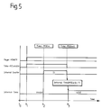
- Figure 5 is a timing diagram of the operation of the pager of figure 4; and
- Figure 6 is a flow diagram of the operation of the pager of figure 4.
- Referring now to figure 1 of the drawings, there is shown an example of the
communications system 1 comprising acentral station 2 which is equipped with atransmitter 3 and acontroller 4. This latter includes means for formatting signals to be transmitted. The signals may include pager identification codes and message data such as time and date information. - One or more paging receivers, or pagers, may be provided in a communications system according to the present invention, however only one such pager, indicated by the
reference numeral 5, is shown in figure 1. Thepager 1 includes aradio receiver 6 tuned to the frequency of thetransmitter 3 and acontroller 7 which controls the energisation of theradio receiver 6, the date and time stamping of received message signals and the energisation of an alerting device, such as an acoustic transducer, in the event of thecontroller 7 identifying the pager's identification code in a transmitted message. - The
communications system 1 also includes a message generator/receiver 8 comprising afirst radio receiver 9 tuned to the frequency of thetransmitter 3, a zone-code generation circuit 10, afurther radio receiver 11 and amessage generating circuit 12. Theradio receiver 11 is tuned to the frequency of a transmitter (not shown) generating real-time messages, such as the Langwellensenders DCF 77 transmitter in Mainflingen, Germany. Alternatively, theradio receiver 11 may be replaced by a real-time clock or other time reference. Themessage generating circuit 12 periodically generates message signals comprising information from theradio receivers central station 2 for transmission to thepager 5. - The communications system of the invention may also comprise a plurality of central stations, each located at the centre of a different zone of transmission within a certain geographical area. Switzerland, for example, comprises five such transmission zones which collectively ensue that a pager is able to receive message information practically anywhere within the country. Figure 2 illustrates a
geographic area 13 as it might be divided into transmission zones such as Z1, Z2, ..., ZN, having a typical region of overlapping coverage as denoted by zone Z4. Other zones may exist within thegeographic area 13 but are not shown. For the sake of clarity, only the zones Z1, Z2 and ZN are represented in figure Z. - Each of the three zones Z1, Z2 and ZN shown in figure 2 have associated therewith a central station and message generator/receiver, such as the
central station 2 and the message generator/receiver 8 shown in figure 1. The transmitter Tx1 of the central station associated with the zone Z1 has a coverage area within thecircle 14, the transmitter Tx2 of the central station associated with the zone Z2 has a coverage area within thecircle 15, and so on all the way up to the transmitter TxN of the central station associated with the zone ZN which has a coverage area within thecircle 16. The zone-code generating circuit 10 shown in figure 1 creates a code representative of the particular zone within which thecentral station 2 is located for inclusion in the message signal generated by themessage generating circuit 12. - The format of the transmitted message signals is CCIR Radiopaging Code No.1, otherwise known by persons in the paging field as POCSAG. This format will now be briefly explained with reference to figures 3A and 3B. The transmissions from the
central station 2 each comprise a series of bursts, each burst comprising a preamble 20 of 576 bits which enables thepager 5 to achieve bit synchronisation, followed bybatches synchronisation codeword 24 which is used by a pager to achieve and maintain synchronisation. The remaining sixteen codewords are paired and each of the eight pairs is termed a frame, i.e. frames F1 to F8. Each pager is assigned to a particular frame which means that, if necessary its pager identification code, will be transmitted in that frame only. The pager must therefore energise its radio receiver firstly to be able to receive thesynchronisation codeword 24 and secondly for the duration of its assigned frame. - Data messages comprise an address codeword plus one or more message codewords. The transmission of date and time messages may occur at regular intervals, for example, once every two minutes, once every certain number of batches, or once every burst. In practice, the repetition of the transmission of such date and time messages may vary from between once-a-minute to once-every-hour depending on the characteristics of the network associated with each central station. In the case of the first of these examples, date, time and zone information is generated once every two minutes by the
message generating circuit 12 and sent to thecentral station 2 for formatting and transmission via thetransmitter 3 as a series of 4-bit hexadecimal characters. The transmitted information may have the form of hour, minute, second, zone, day, month and year, such as 12 hours, 15 minutes, 35 seconds,zone 3, 29 December 1994. The message signal generated by themessage generating circuit 12 may thus be the 4-bit hexadecimal equivalent of :
12_15_35_03_29_12_94,
where the symbol "_" represents a character separator. - More particularly, the first code word in the frame assigned to the
pager 5 includes function bits indicative of the fact that the following code words either contain date, time and zone information or that they do not. A paging receiver wishing to receive such a message signal is programmed to energise its radio receiver in order to check if this code-word contains date, time and zone information, and if so, to remain energised for these frames. - Referring to figure 4, the
pager 5 comprises theradio receiver 6 and thecontroller 7 shown in figure 1. Thepager 5 further comprises adecoder 30 connected between the output of thereceiver 6 and an input to thecontroller 7. Thedecoder 30 accepts any signal received during the periods when the receiver is energised and sends each codeword of the signal to thecontroller 7. - This latter firstly checks whether the address codeword corresponds to one of the identification codes stored within the controller's memory. If there is correspondence, the
controller 7 causes analert device 31 to be energised. If the received signal comprises data message codewords, thecontroller 7 stores these together with a date and time stamp in aRAM 32. In response to a user command via akeypad 33 or other user input device, thecontroller 7 causes the contents of theRAM 32 to be read out and supplied to adata display device 34. In addition, thepager 5 also includesmeans 35 for displaying the current time-of-day comprising amotor controller 36, amotor 37 for driving adisplay device 38, such as the hour and minute hand of a watch dial. - A
timing stage 39 is connected to thecontroller 7 and provides an internal time signal to thecontroller 7 so that it can carry out various operations, including, for example, the display of the current time-of-day to the user via the time display means 35. Thetiming stage 39 includes acounter 40 and anoscillator 41 for providing timing pulses to thecounter 40. When thepager 5 is firstly energised, the contents of thecounter 40 do not correspond to the current time-of-day. Referring now to figure 5, upon receipt of a first time message signal (Time-MSG x), thecontroller 7 sends a signal at an output 7a to reset the contents of thecounter 40 to zero. Thereafter, the contents of thecounter 7 increases at a rate set by theoscillator 41. - Upon receipt of a subsequent time message signal (Time-MSG x+1) at a time T1 after the receipt of the first time message signal, the
controller 7 firstly verifies that this subsequent time message signal contains the same zone code as does the previous time message signal. If this is the case, the controller stores the year, month, day, zone and time information in aRAM 42. The inclusion of a code identifying the zone from which the time message signal was transmitted enables thecontroller 7 to assure that the first and subsequent time message signals have been transmitted by the same central station. - In this way, the time information contained in the second time message signal relates to the first time message signal, rather than to a time message signal detected by a pager but transmitted by another central station within the communications system. This will be notably the case if the
pager 5 is used in an area in which two or more transmission zones overlap, as is shown in figure 2 by the zone Z4. Prior art communications systems, such as that disclosed in US Patent No. 5 241 305, are incapable of distinguishing between time message signals transmitted by different central stations therewithin. Accordingly, the time message signals of such a prior art communications system cannot be used to accurately set the internal clock of a pager operating in such a communications system when the pager is used in a region of overlapping zones i.e. zone Z4 of figure 2. - The
controller 7 then supplies thecounter 40 with the value of the time information and, upon sending a signal from its output 7b, causes the time information value to be added to the contents of thecounter 40. As will be explained shortly, this series of operations has the effect of setting the contents of thecounter 40 to a value representative of the current time-of-day. - Referring once again to figure 1, a time message signal is generated by the
message generating circuit 12 and is supplied to thecontroller 4 of thecentral station 2. Thecontroller 4 adapts the signal to an appropriate format and stores it temporarily in readiness for transmission by thetransmitter 3 at the required moment, that is, in the assigned frame of a message signal and when thetransmitter 3 is not occupied with the transmission of other message signals. The date and time signal is received by those pagers adapted to receive these signals. However, due to the fact that the actual time of broadcast of a time message differs from the time information coded in the message, thecounter 40 of thepager 5 can not be set directly from this information. - The manner in which the
counter 40 of thepager 5 is set so as to indicate the current time-of-day will be now explained with reference to figures 5 and 6. At a time t₀, thepager 5 is not energised and the contents of thecounter 40 are zero. Under these conditions, the internal time, as represented by the contents of thecounter 40, is invalid. At a time t₁, thepager 5 is switched on by its user and thepager 5 passes into a state whereby the updating of the contents of thecounter 40 is enabled. - As seen in figure 6, the timing means 8 periodically receives time message signals from the
central station 2 and generates time message signals for transmission by thecentral station 2. When, at the step S1, a time message signal is generated, the current time-of-day as received by thetransmitter 11 is included in that time message. This time message (Time-MSG x) is sent to thecentral station 2 and transmitted, after a certain delay, by thetransmitter 3 at a time t₂. In response to the detection of this time message signal, thecontroller 7 of thepager 5 resets thecounter 40 to zero. - At the step S2, the timing means 8 detects whether or not the time message signal last generated has been received by the
receiver 9. If this time message signal has been received and, at step S3, it is decided that more than two minutes have passed since the reception of the last time message signal from the central station, the timing means 8 generates, at step S4, a new time message signal (Time-MSG x+1) The time information in this time message signal corresponds to the current time-of-day from thereceiver 11, when the previous time message signal was received. - After a certain delay, this time message signal is transmitted by the
transmitter 3 and detected, at a time t₃, by thepager 5. Thecontroller 7 stores the time information in this second time message signal in theRAM 42 and then adds a value representative of this information to the contents of thecounter 40. After this operation, the contents of thecounter 40 are representative of the value (Time-MSG x+1) + T1 and hence of the current time-of-day. - By way of example, a time message signal containing the time information 12:00:00 may be generated by the timing means 8 (this time information being the time of receipt of the previously transmitted time message signal), but may not be transmitted by the
transmitter 3 until 12:03:01. The detection of this time message signal causes thecounter 40 to be reset to zero, but due to the pulse from theoscillator 41, it continues counting at a real-time rate. - Having detected this first time message, the timing means 8 generates a subsequent time message signal, containing the time information 12:03:01. This time message signal may not be transmitted until 12:07:35.
- When this subsequent time message signal is detected by the
receiver 6, the contents of thecounter 40 are representative of the time 00:04:34, that is, the difference in time between the detection of the first time message signal at 12:03:01 and the detection of the second time message signal at 12:07:35. At this moment, thecontroller 7 adds a value corresponding to 12:03:01, that is, the time information contained in the time message signal transmitted at the time 12:07:35, to the contents of thecounter 40. The contents of thecounter 40 thus have value corresponding to the time 12:07:35. In other words, thecounter 40 has been set to the current time-of-day in a simple and efficient manner that does not require the transmission of an error signal. The number of characters which must be transmitted by thecentral station 2 with each time message signal is therefore less than in existing communications systems and results in a reduction in the air-time loss due to this transmission. - Finally, it is to be understood that various modifications and/or additions may be made to the communications system and receiver without departing from the ambit of the present invention as defined in the claims appended hereto. For example, a further reduction in the air-time loss may be had in eliminating the character separators from each time message signal transmitted by each central station in the communications system.
- Whilst the invention has been described in relation to the POCSAG format of transmitting message signals, it is to be appreciated that any other appropriate format, such as GOLAY, may also be used therewith.
Claims (12)
- Communications system comprising :- means (12) for generating a succession of time message signals;- a central station (2) having means for transmitting said time message signals;- at least a first receiver (5) for receiving said time message signals; and- timing means (9,10,11) for determining the real time of receipt of each time message signal,
characterised in that
each said time message signal is representative of the real time of receipt by said first receiver of a preceding time message signal,
and in that said first receiver comprises:- clock means (40,41) for providing said first receiver with an internal time signal;- means (7,7a) for resetting said clock means upon the receipt of a first time message signal; and- means (7,7b,42) for advancing said clock means, upon receipt of a subsequent time message signal, by the real time indicated by said subsequent time message signal. - Communications system according to claim 1, characterised in that
said clock means comprises :- a counter (40) having an output for providing said internal time signal; and- means (41) for incrementing the contents of said counter at a known frequency. - Communications system according to claim 2, characterised in that
said means for advancing said clock means comprises:- means (7,7b,42) for adding a value representative of the real time indicated by said subsequent time message signal to the contents of said counter. - Communications system according to any one of the preceding claims, characterised in that
said timing means comprise :- a second receiver (9) for receiving said time message signals; and- means (11) for determining the real time of receipt of each time message signal by said second receiver. - Communications system according to claim 4, characterised in that
said means (11) for determining the real time of receipt of each time message signal comprise a real time clock. - Communications system according to claim 4, characterised in that
said means (11) for determining the real time of receipt of each time message signal comprise a third receiver for receiving real-time messages. - Communications system according to any one of the preceding claims, characterised in that
said timing means comprise :- means (10) for generating a zone-code for inclusion in said time message signals, said zone-code being indicative of the transmission coverage area of said central station. - Communications system according to claim 7, characterised in that
said first receiver (5) comprises :- means (7) for assuring that said first and said subsequent time-message signals include the same zone-code. - Receiver for use in a communications system in which a succession of time message signals are transmitted by a central station, characterised in that said receiver (5) comprises :- means (6) for receiving said time message signals;- clock means (40,41) for providing said first receiver with an internal time signal;- means (7,7a) for resetting said clock means upon the receipt of a first time message signal; and- means (7,7b,42) for advancing said clock means, upon receipt of a subsequent time message signal, by the real time indicated by said subsequent time message signal.
- Receiver according to claim 9, characterised in that
said clock means comprises :- a counter (40) having an output for providing said internal time signal; and- means (41) for incrementing the contents of said counter at a known frequency. - Receiver according to claim 10, characterised in that
said means for advancing said clock means comprises :- means (7,7b,42) for adding a value representative of the real time indicated by said subsequent time message signal to the contents of said counter. - Receiver any one of claims 9 to 11, wherein said time message signals comprise a zone-code indicative of the transmission coverage area of said central station, said receiver being characterised in that it further comprises :- means (7) for assuring that said first and said subsequent time-message signals include the same zone-code.
Priority Applications (16)
| Application Number | Priority Date | Filing Date | Title |
|---|---|---|---|
| DE69411918T DE69411918T2 (en) | 1994-09-24 | 1994-09-24 | Time measurement in a communication system, communication system and receiver therefor |
| AT94115093T ATE168793T1 (en) | 1994-09-24 | 1994-09-24 | TIME MEASUREMENT IN A COMMUNICATION SYSTEM, COMMUNICATION SYSTEM AND RECEIVER THEREOF |
| DK94115093T DK0703514T3 (en) | 1994-09-24 | 1994-09-24 | Time measurement in a communication system as well as a communication system and a receiver for use in such a system |
| EP94115093A EP0703514B1 (en) | 1994-09-24 | 1994-09-24 | Time measurement in a communications system, a communications system and a receiver for use in such a system |
| TW084108796A TW281843B (en) | 1994-09-24 | 1995-08-23 | |
| US08/522,575 US5774057A (en) | 1994-09-24 | 1995-09-01 | Time measurement in a communications system, a communications system and a receiver for use in such a system |
| JP7232735A JPH08182034A (en) | 1994-09-24 | 1995-09-11 | Communication system |
| ZA957700A ZA957700B (en) | 1994-09-24 | 1995-09-13 | Time measurement in a communications system a communications system and a receiver for use in such a system |
| CA002158693A CA2158693A1 (en) | 1994-09-24 | 1995-09-20 | Time measurement in a communications system, a communications system and a receiver for use in such a system |
| KR1019950030982A KR960011597A (en) | 1994-09-24 | 1995-09-21 | Time measurement and communication systems in telecommunication systems and receivers used in these systems |
| FI954462A FI954462A (en) | 1994-09-24 | 1995-09-21 | Time measurement in a communication system, a communication system and a receiver for use in such a system |
| NO953750A NO953750L (en) | 1994-09-24 | 1995-09-22 | Transmitter / receiver system for transmitting time and clock signals |
| BR9504134A BR9504134A (en) | 1994-09-24 | 1995-09-22 | Communications system and receiver for communications system |
| AU32854/95A AU692592B2 (en) | 1994-09-24 | 1995-09-22 | Time measurement in a communications system, a communications system and a receiver for use in such a system |
| CN95116754A CN1183697A (en) | 1994-09-24 | 1995-09-22 | Time measurement in communications system, communication system and receiver for use in such system |
| IL11541195A IL115411A (en) | 1994-09-24 | 1995-09-22 | Communications system containing means for time measurement |
Applications Claiming Priority (1)
| Application Number | Priority Date | Filing Date | Title |
|---|---|---|---|
| EP94115093A EP0703514B1 (en) | 1994-09-24 | 1994-09-24 | Time measurement in a communications system, a communications system and a receiver for use in such a system |
Publications (2)
| Publication Number | Publication Date |
|---|---|
| EP0703514A1 true EP0703514A1 (en) | 1996-03-27 |
| EP0703514B1 EP0703514B1 (en) | 1998-07-22 |
Family
ID=8216324
Family Applications (1)
| Application Number | Title | Priority Date | Filing Date |
|---|---|---|---|
| EP94115093A Expired - Lifetime EP0703514B1 (en) | 1994-09-24 | 1994-09-24 | Time measurement in a communications system, a communications system and a receiver for use in such a system |
Country Status (16)
| Country | Link |
|---|---|
| US (1) | US5774057A (en) |
| EP (1) | EP0703514B1 (en) |
| JP (1) | JPH08182034A (en) |
| KR (1) | KR960011597A (en) |
| CN (1) | CN1183697A (en) |
| AT (1) | ATE168793T1 (en) |
| AU (1) | AU692592B2 (en) |
| BR (1) | BR9504134A (en) |
| CA (1) | CA2158693A1 (en) |
| DE (1) | DE69411918T2 (en) |
| DK (1) | DK0703514T3 (en) |
| FI (1) | FI954462A (en) |
| IL (1) | IL115411A (en) |
| NO (1) | NO953750L (en) |
| TW (1) | TW281843B (en) |
| ZA (1) | ZA957700B (en) |
Cited By (2)
| Publication number | Priority date | Publication date | Assignee | Title |
|---|---|---|---|---|
| WO1996027822A1 (en) * | 1995-03-03 | 1996-09-12 | Nexus 1994 Limited | Synchronization system for a shared channel communication system |
| WO1999061960A1 (en) * | 1998-05-25 | 1999-12-02 | Nanyang Polytechnic | Wireless synchronous clock system |
Families Citing this family (17)
| Publication number | Priority date | Publication date | Assignee | Title |
|---|---|---|---|---|
| JP3204614B2 (en) | 1996-06-21 | 2001-09-04 | 松下電器産業株式会社 | Wireless receiver |
| US6144652A (en) * | 1996-11-08 | 2000-11-07 | Lucent Technologies Inc. | TDM-based fixed wireless loop system |
| US6230027B1 (en) * | 1997-06-17 | 2001-05-08 | U.S. Philips Corporation | Method of issuing a time information signal via a satellite station of a transmission system |
| US6223050B1 (en) * | 1997-12-09 | 2001-04-24 | Bellsouth Intellectual Property Management Corporation | System and method for automatically setting a remote timepiece with the correct time |
| KR100545805B1 (en) * | 1998-03-04 | 2006-04-14 | 엘지전자 주식회사 | How to display time during communication |
| US6088578A (en) * | 1998-03-26 | 2000-07-11 | Nortel Networks Corporation | Burst request method and apparatus for CDMA high speed data |
| US6101370A (en) * | 1998-07-06 | 2000-08-08 | Motorola | Method and apparatus used in a simulcast radio communication system for providing improved local time |
| DE29819806U1 (en) * | 1998-11-05 | 2000-03-16 | Siemens Ag | Network participants |
| JP3743819B2 (en) * | 1999-04-09 | 2006-02-08 | カシオ計算機株式会社 | Electronic device with clock function, time information correction method |
| DE10133658B4 (en) * | 2001-07-11 | 2004-02-05 | Siemens Ag | Method and device for distance-independent transmission of energy and time information between a receiving device and a synchronization device |
| KR100426451B1 (en) * | 2002-04-03 | 2004-04-13 | 김형곤 | A method of reduction of Polyester wig-silk weight |
| US7230884B2 (en) * | 2003-01-03 | 2007-06-12 | The Sapling Company, Inc. | Clock diagnostics |
| KR100605168B1 (en) * | 2004-11-23 | 2006-07-31 | 삼성전자주식회사 | Time setting method automatically and digital broadcast receiving apparatus to be applied to the same |
| US7509150B1 (en) | 2005-08-02 | 2009-03-24 | Itt Manufacturing Enterprises, Inc. | Reducing power consumption in a radio device by early receiver shut down |
| US7565261B2 (en) * | 2006-09-29 | 2009-07-21 | Hewlett-Packard Development Company, L.P. | Generating an alert to indicate stale data |
| EP3432090B1 (en) | 2016-03-15 | 2021-05-05 | Citizen Watch Co., Ltd. | Electronic watch and communication control system |
| KR102203427B1 (en) | 2019-07-11 | 2021-01-15 | (주)씨와이씨 | Apparatus for producing synthetic wig hair filament |
Citations (20)
| Publication number | Priority date | Publication date | Assignee | Title |
|---|---|---|---|---|
| US3684964A (en) | 1970-08-07 | 1972-08-15 | Hathaway Instr Inc | Decoding system and method for generating time signals |
| US4204398A (en) | 1977-09-16 | 1980-05-27 | Lemelson Jerome H | Method and means for automatically setting timepieces in a time zone |
| GB1596628A (en) * | 1978-01-23 | 1981-08-26 | Plessey Co Ltd Heriter F A | Indicating devices |
| US4337463A (en) * | 1980-08-22 | 1982-06-29 | Control Data Corporation | Time synchronization master station and remote station system |
| WO1984001630A1 (en) | 1982-10-07 | 1984-04-26 | Richard John Walters | A time display system |
| WO1985000441A1 (en) | 1983-07-08 | 1985-01-31 | Western Electric Company, Inc. | Synchronization of real-time clocks in a packet switching system |
| EP0155628A1 (en) | 1984-03-13 | 1985-09-25 | Nec Corporation | Paging receivers |
| AU5207886A (en) | 1984-12-05 | 1986-07-01 | Seiko Corporation | Watch pager system and communication protocol |
| US4713808A (en) | 1985-11-27 | 1987-12-15 | A T & E Corporation | Watch pager system and communication protocol |
| EP0258838A2 (en) | 1986-09-01 | 1988-03-09 | Siemens Aktiengesellschaft | Process for actualizing the local time of a user of an information tranfer system |
| US4768178A (en) | 1987-02-24 | 1988-08-30 | Precision Standard Time, Inc. | High precision radio signal controlled continuously updated digital clock |
| US4818987A (en) | 1985-12-18 | 1989-04-04 | Nec Corporation | Selective paging receiver with message display |
| US4823328A (en) | 1987-08-27 | 1989-04-18 | Conklin Charles C | Radio signal controlled digital clock |
| US4839641A (en) | 1984-10-12 | 1989-06-13 | Nec Corporation | Pager receiver capable of controlling an internal state by a call signal |
| US4845491A (en) | 1987-05-15 | 1989-07-04 | Newspager Corporation Of America | Pager based information system |
| WO1991016670A1 (en) | 1990-04-18 | 1991-10-31 | At&E Corporation | Method and apparatus for accurate time maintenance and display |
| EP0461849A2 (en) | 1990-06-12 | 1991-12-18 | Seiko Epson Corporation | Paging receiver with a time piece function |
| AU8367791A (en) | 1990-09-07 | 1992-03-12 | Nec Corporation | Apparatus for displaying time-of-day data adaptively to different time zones |
| EP0561220A1 (en) | 1992-03-16 | 1993-09-22 | Siemens Aktiengesellschaft | Process for operating a steam generating system and steam generator |
| EP0564220A2 (en) * | 1992-03-31 | 1993-10-06 | Glenayre Electronics, Inc. | Clock synchronization system |
Family Cites Families (9)
| Publication number | Priority date | Publication date | Assignee | Title |
|---|---|---|---|---|
| SE435438B (en) * | 1982-12-09 | 1984-09-24 | Ericsson Telefon Ab L M | PROCEDURE FOR SETTING THE RADIO TRANSMITTER AT THE SAME TIME TRANSMISSION |
| US4746920A (en) * | 1986-03-28 | 1988-05-24 | Tandem Computers Incorporated | Method and apparatus for clock management |
| US4879758A (en) * | 1987-01-02 | 1989-11-07 | Motorola, Inc. | Communication receiver system having a decoder operating at variable frequencies |
| US5241305A (en) * | 1987-05-15 | 1993-08-31 | Newspager Corporation Of America | Paper multi-level group messaging with group parsing by message |
| US5001471A (en) * | 1989-12-26 | 1991-03-19 | Motorola, Inc. | Paging system employing designated batch information service data message transmission |
| GB9207861D0 (en) * | 1992-04-09 | 1992-05-27 | Philips Electronics Uk Ltd | A method of time measurement in a communications system,a communications system and a receiving apparatus for use in the system |
| JPH0832086B2 (en) * | 1993-04-21 | 1996-03-27 | 日本電気株式会社 | Wireless selective call receiver |
| US5592607A (en) * | 1993-10-15 | 1997-01-07 | Xerox Corporation | Interactive method and system for producing address-correlated information using user-specified address zones |
| EP0656732A1 (en) * | 1993-12-03 | 1995-06-07 | Firma Erika Köchler | A method and a network for transmitting local and global radio calls |
-
1994
- 1994-09-24 EP EP94115093A patent/EP0703514B1/en not_active Expired - Lifetime
- 1994-09-24 DK DK94115093T patent/DK0703514T3/en active
- 1994-09-24 AT AT94115093T patent/ATE168793T1/en active
- 1994-09-24 DE DE69411918T patent/DE69411918T2/en not_active Expired - Fee Related
-
1995
- 1995-08-23 TW TW084108796A patent/TW281843B/zh active
- 1995-09-01 US US08/522,575 patent/US5774057A/en not_active Expired - Fee Related
- 1995-09-11 JP JP7232735A patent/JPH08182034A/en active Pending
- 1995-09-13 ZA ZA957700A patent/ZA957700B/en unknown
- 1995-09-20 CA CA002158693A patent/CA2158693A1/en not_active Abandoned
- 1995-09-21 KR KR1019950030982A patent/KR960011597A/en not_active Application Discontinuation
- 1995-09-21 FI FI954462A patent/FI954462A/en unknown
- 1995-09-22 IL IL11541195A patent/IL115411A/en not_active IP Right Cessation
- 1995-09-22 BR BR9504134A patent/BR9504134A/en not_active Application Discontinuation
- 1995-09-22 NO NO953750A patent/NO953750L/en not_active Application Discontinuation
- 1995-09-22 CN CN95116754A patent/CN1183697A/en active Pending
- 1995-09-22 AU AU32854/95A patent/AU692592B2/en not_active Withdrawn - After Issue
Patent Citations (21)
| Publication number | Priority date | Publication date | Assignee | Title |
|---|---|---|---|---|
| US3684964A (en) | 1970-08-07 | 1972-08-15 | Hathaway Instr Inc | Decoding system and method for generating time signals |
| US4204398A (en) | 1977-09-16 | 1980-05-27 | Lemelson Jerome H | Method and means for automatically setting timepieces in a time zone |
| GB1596628A (en) * | 1978-01-23 | 1981-08-26 | Plessey Co Ltd Heriter F A | Indicating devices |
| US4337463A (en) * | 1980-08-22 | 1982-06-29 | Control Data Corporation | Time synchronization master station and remote station system |
| WO1984001630A1 (en) | 1982-10-07 | 1984-04-26 | Richard John Walters | A time display system |
| WO1985000441A1 (en) | 1983-07-08 | 1985-01-31 | Western Electric Company, Inc. | Synchronization of real-time clocks in a packet switching system |
| EP0155628A1 (en) | 1984-03-13 | 1985-09-25 | Nec Corporation | Paging receivers |
| US4839641A (en) | 1984-10-12 | 1989-06-13 | Nec Corporation | Pager receiver capable of controlling an internal state by a call signal |
| AU5207886A (en) | 1984-12-05 | 1986-07-01 | Seiko Corporation | Watch pager system and communication protocol |
| US4713808A (en) | 1985-11-27 | 1987-12-15 | A T & E Corporation | Watch pager system and communication protocol |
| US4818987A (en) | 1985-12-18 | 1989-04-04 | Nec Corporation | Selective paging receiver with message display |
| EP0258838A2 (en) | 1986-09-01 | 1988-03-09 | Siemens Aktiengesellschaft | Process for actualizing the local time of a user of an information tranfer system |
| US4768178A (en) | 1987-02-24 | 1988-08-30 | Precision Standard Time, Inc. | High precision radio signal controlled continuously updated digital clock |
| US4845491A (en) | 1987-05-15 | 1989-07-04 | Newspager Corporation Of America | Pager based information system |
| US4823328A (en) | 1987-08-27 | 1989-04-18 | Conklin Charles C | Radio signal controlled digital clock |
| WO1991016670A1 (en) | 1990-04-18 | 1991-10-31 | At&E Corporation | Method and apparatus for accurate time maintenance and display |
| EP0461849A2 (en) | 1990-06-12 | 1991-12-18 | Seiko Epson Corporation | Paging receiver with a time piece function |
| AU8367791A (en) | 1990-09-07 | 1992-03-12 | Nec Corporation | Apparatus for displaying time-of-day data adaptively to different time zones |
| EP0475298A1 (en) | 1990-09-07 | 1992-03-18 | Nec Corporation | Apparatus for displaying time-of-day data adaptively to different time zones |
| EP0561220A1 (en) | 1992-03-16 | 1993-09-22 | Siemens Aktiengesellschaft | Process for operating a steam generating system and steam generator |
| EP0564220A2 (en) * | 1992-03-31 | 1993-10-06 | Glenayre Electronics, Inc. | Clock synchronization system |
Cited By (4)
| Publication number | Priority date | Publication date | Assignee | Title |
|---|---|---|---|---|
| US5712867A (en) * | 1992-10-15 | 1998-01-27 | Nexus 1994 Limited | Two-way paging apparatus having highly accurate frequency hopping synchronization |
| WO1996027822A1 (en) * | 1995-03-03 | 1996-09-12 | Nexus 1994 Limited | Synchronization system for a shared channel communication system |
| WO1999061960A1 (en) * | 1998-05-25 | 1999-12-02 | Nanyang Polytechnic | Wireless synchronous clock system |
| SG81231A1 (en) * | 1998-05-25 | 2001-06-19 | Nanyang Polytechnic | Wireless synchronous clock system |
Also Published As
| Publication number | Publication date |
|---|---|
| DK0703514T3 (en) | 1999-04-26 |
| FI954462A (en) | 1996-03-25 |
| FI954462A0 (en) | 1995-09-21 |
| AU692592B2 (en) | 1998-06-11 |
| NO953750L (en) | 1996-03-25 |
| CN1183697A (en) | 1998-06-03 |
| EP0703514B1 (en) | 1998-07-22 |
| US5774057A (en) | 1998-06-30 |
| IL115411A (en) | 1999-04-11 |
| ATE168793T1 (en) | 1998-08-15 |
| ZA957700B (en) | 1996-04-24 |
| DE69411918D1 (en) | 1998-08-27 |
| JPH08182034A (en) | 1996-07-12 |
| KR960011597A (en) | 1996-04-20 |
| IL115411A0 (en) | 1995-12-31 |
| DE69411918T2 (en) | 1999-03-25 |
| CA2158693A1 (en) | 1996-03-25 |
| NO953750D0 (en) | 1995-09-22 |
| AU3285495A (en) | 1996-04-04 |
| TW281843B (en) | 1996-07-21 |
| BR9504134A (en) | 1996-07-30 |
Similar Documents
| Publication | Publication Date | Title |
|---|---|---|
| EP0703514B1 (en) | Time measurement in a communications system, a communications system and a receiver for use in such a system | |
| US5363377A (en) | Communications system and receiver for use therein which indicates time based on a selected time message signal from a central station | |
| US5150954A (en) | Pager watch system utilizing time slot communication | |
| US5859595A (en) | System for providing paging receivers with accurate time of day information | |
| EP0511008B1 (en) | Wireless communication system | |
| US5463382A (en) | Method and apparatus for controlling message transmissions in an acknowledge-back selective call communication system | |
| US5629940A (en) | Transmitting and receiving long messages in a wireless one-way communication system while reserving selected slots for short messages | |
| US5473612A (en) | Method and apparatus for minimizing false detection of packet data in a communication receiver | |
| EP0619685B1 (en) | Timepiece for radio display pager synchronised to the local standard time | |
| EP0203140B1 (en) | A method and apparatus in radio reception for avoiding storing a message more than once | |
| WO1999030213A2 (en) | System and method for automatically setting a remote timepiece with the correct time | |
| US5739762A (en) | Time correction system for radio selective calling receiver | |
| US4870403A (en) | Paging receiver with a capability of receiving or inhibiting message data | |
| EP0609102A1 (en) | Paging receiver suitable for an emergency call | |
| CA1262385A (en) | Pager watch system utilizing time slot communication | |
| US5606728A (en) | Method and apparatus for reducing power consumption in a selective call radio | |
| RU2178238C2 (en) | Discriminating-call system and its secondary station | |
| JP3796380B2 (en) | Time correction information output device and automatic time correction clock | |
| EP0413963B1 (en) | Radio communication apparatus for rapidly knowing whether the apparatus is within or out of a service area | |
| EP0618743B1 (en) | Time division multiplexed communication method and system for increasing the number of individual receivers than can be served | |
| US5960326A (en) | Radio apparatus outputting an alarm prior to a scheduled time | |
| CA2187063A1 (en) | Synchronization of a timepiece to a reference time | |
| KR950011078B1 (en) | Selective calling system | |
| KR100279382B1 (en) | Method of transmitting character information using pager transmission network | |
| WO1991011868A1 (en) | Paging system with time slot reassignment |
Legal Events
| Date | Code | Title | Description |
|---|---|---|---|
| PUAI | Public reference made under article 153(3) epc to a published international application that has entered the european phase |
Free format text: ORIGINAL CODE: 0009012 |
|
| AK | Designated contracting states |
Kind code of ref document: A1 Designated state(s): AT BE CH DE DK ES FR GB GR IT LI LU NL SE |
|
| 17P | Request for examination filed |
Effective date: 19960927 |
|
| GRAG | Despatch of communication of intention to grant |
Free format text: ORIGINAL CODE: EPIDOS AGRA |
|
| 17Q | First examination report despatched |
Effective date: 19970917 |
|
| GRAG | Despatch of communication of intention to grant |
Free format text: ORIGINAL CODE: EPIDOS AGRA |
|
| GRAH | Despatch of communication of intention to grant a patent |
Free format text: ORIGINAL CODE: EPIDOS IGRA |
|
| TPAD | Observations filed by third parties |
Free format text: ORIGINAL CODE: EPIDOS TIPA |
|
| GRAH | Despatch of communication of intention to grant a patent |
Free format text: ORIGINAL CODE: EPIDOS IGRA |
|
| GRAA | (expected) grant |
Free format text: ORIGINAL CODE: 0009210 |
|
| AK | Designated contracting states |
Kind code of ref document: B1 Designated state(s): AT BE CH DE DK ES FR GB GR IT LI LU NL SE |
|
| PG25 | Lapsed in a contracting state [announced via postgrant information from national office to epo] |
Ref country code: IT Free format text: LAPSE BECAUSE OF FAILURE TO SUBMIT A TRANSLATION OF THE DESCRIPTION OR TO PAY THE FEE WITHIN THE PRE;WARNING: LAPSES OF ITALIAN PATENTS WITH EFFECTIVE DATE BEFORE 2007 MAY HAVE OCCURRED AT ANY TIME BEFORE 2007. THE CORRECT EFFECTIVE DATE MAY BE DIFFERENT FROM THE ONE RECORDED.SCRIBED TIME-LIMIT Effective date: 19980722 Ref country code: GR Free format text: LAPSE BECAUSE OF FAILURE TO SUBMIT A TRANSLATION OF THE DESCRIPTION OR TO PAY THE FEE WITHIN THE PRESCRIBED TIME-LIMIT Effective date: 19980722 Ref country code: ES Free format text: THE PATENT HAS BEEN ANNULLED BY A DECISION OF A NATIONAL AUTHORITY Effective date: 19980722 Ref country code: BE Free format text: LAPSE BECAUSE OF FAILURE TO SUBMIT A TRANSLATION OF THE DESCRIPTION OR TO PAY THE FEE WITHIN THE PRESCRIBED TIME-LIMIT Effective date: 19980722 Ref country code: AT Free format text: LAPSE BECAUSE OF FAILURE TO SUBMIT A TRANSLATION OF THE DESCRIPTION OR TO PAY THE FEE WITHIN THE PRESCRIBED TIME-LIMIT Effective date: 19980722 |
|
| REF | Corresponds to: |
Ref document number: 168793 Country of ref document: AT Date of ref document: 19980815 Kind code of ref document: T |
|
| REG | Reference to a national code |
Ref country code: CH Ref legal event code: EP |
|
| REF | Corresponds to: |
Ref document number: 69411918 Country of ref document: DE Date of ref document: 19980827 |
|
| PG25 | Lapsed in a contracting state [announced via postgrant information from national office to epo] |
Ref country code: LU Free format text: LAPSE BECAUSE OF NON-PAYMENT OF DUE FEES Effective date: 19980924 |
|
| REG | Reference to a national code |
Ref country code: CH Ref legal event code: NV Representative=s name: ICB INGENIEURS CONSEILS EN BREVETS SA |
|
| ET | Fr: translation filed | ||
| REG | Reference to a national code |
Ref country code: DK Ref legal event code: T3 |
|
| PLBE | No opposition filed within time limit |
Free format text: ORIGINAL CODE: 0009261 |
|
| STAA | Information on the status of an ep patent application or granted ep patent |
Free format text: STATUS: NO OPPOSITION FILED WITHIN TIME LIMIT |
|
| 26N | No opposition filed | ||
| PGFP | Annual fee paid to national office [announced via postgrant information from national office to epo] |
Ref country code: DK Payment date: 19990825 Year of fee payment: 6 |
|
| PGFP | Annual fee paid to national office [announced via postgrant information from national office to epo] |
Ref country code: SE Payment date: 19990830 Year of fee payment: 6 |
|
| PGFP | Annual fee paid to national office [announced via postgrant information from national office to epo] |
Ref country code: NL Payment date: 19990831 Year of fee payment: 6 Ref country code: GB Payment date: 19990831 Year of fee payment: 6 |
|
| PGFP | Annual fee paid to national office [announced via postgrant information from national office to epo] |
Ref country code: DE Payment date: 19990903 Year of fee payment: 6 |
|
| PGFP | Annual fee paid to national office [announced via postgrant information from national office to epo] |
Ref country code: FR Payment date: 19990929 Year of fee payment: 6 |
|
| PGFP | Annual fee paid to national office [announced via postgrant information from national office to epo] |
Ref country code: CH Payment date: 19990930 Year of fee payment: 6 |
|
| PG25 | Lapsed in a contracting state [announced via postgrant information from national office to epo] |
Ref country code: GB Free format text: LAPSE BECAUSE OF NON-PAYMENT OF DUE FEES Effective date: 20000924 Ref country code: DK Free format text: LAPSE BECAUSE OF NON-PAYMENT OF DUE FEES Effective date: 20000924 |
|
| PG25 | Lapsed in a contracting state [announced via postgrant information from national office to epo] |
Ref country code: SE Free format text: THE PATENT HAS BEEN ANNULLED BY A DECISION OF A NATIONAL AUTHORITY Effective date: 20000929 |
|
| PG25 | Lapsed in a contracting state [announced via postgrant information from national office to epo] |
Ref country code: LI Free format text: LAPSE BECAUSE OF NON-PAYMENT OF DUE FEES Effective date: 20000930 Ref country code: CH Free format text: LAPSE BECAUSE OF NON-PAYMENT OF DUE FEES Effective date: 20000930 |
|
| PG25 | Lapsed in a contracting state [announced via postgrant information from national office to epo] |
Ref country code: NL Free format text: LAPSE BECAUSE OF NON-PAYMENT OF DUE FEES Effective date: 20010401 |
|
| REG | Reference to a national code |
Ref country code: CH Ref legal event code: PL |
|
| GBPC | Gb: european patent ceased through non-payment of renewal fee |
Effective date: 20000924 |
|
| EUG | Se: european patent has lapsed |
Ref document number: 94115093.0 |
|
| REG | Reference to a national code |
Ref country code: DK Ref legal event code: EBP |
|
| PG25 | Lapsed in a contracting state [announced via postgrant information from national office to epo] |
Ref country code: FR Free format text: LAPSE BECAUSE OF NON-PAYMENT OF DUE FEES Effective date: 20010531 |
|
| NLV4 | Nl: lapsed or anulled due to non-payment of the annual fee |
Effective date: 20010401 |
|
| PG25 | Lapsed in a contracting state [announced via postgrant information from national office to epo] |
Ref country code: DE Free format text: LAPSE BECAUSE OF NON-PAYMENT OF DUE FEES Effective date: 20010601 |
|
| REG | Reference to a national code |
Ref country code: FR Ref legal event code: ST |