EP0703430A2 - Procedure to calibrate a coordinate-measuring machine with two rotational axes - Google Patents
Procedure to calibrate a coordinate-measuring machine with two rotational axes Download PDFInfo
- Publication number
- EP0703430A2 EP0703430A2 EP95114032A EP95114032A EP0703430A2 EP 0703430 A2 EP0703430 A2 EP 0703430A2 EP 95114032 A EP95114032 A EP 95114032A EP 95114032 A EP95114032 A EP 95114032A EP 0703430 A2 EP0703430 A2 EP 0703430A2
- Authority
- EP
- European Patent Office
- Prior art keywords
- calibration
- rotation
- axes
- geometric elements
- probe
- Prior art date
- Legal status (The legal status is an assumption and is not a legal conclusion. Google has not performed a legal analysis and makes no representation as to the accuracy of the status listed.)
- Granted
Links
Images

Classifications
-
- G—PHYSICS
- G01—MEASURING; TESTING
- G01B—MEASURING LENGTH, THICKNESS OR SIMILAR LINEAR DIMENSIONS; MEASURING ANGLES; MEASURING AREAS; MEASURING IRREGULARITIES OF SURFACES OR CONTOURS
- G01B21/00—Measuring arrangements or details thereof, where the measuring technique is not covered by the other groups of this subclass, unspecified or not relevant
- G01B21/02—Measuring arrangements or details thereof, where the measuring technique is not covered by the other groups of this subclass, unspecified or not relevant for measuring length, width, or thickness
- G01B21/04—Measuring arrangements or details thereof, where the measuring technique is not covered by the other groups of this subclass, unspecified or not relevant for measuring length, width, or thickness by measuring coordinates of points
- G01B21/042—Calibration or calibration artifacts
Landscapes
- Physics & Mathematics (AREA)
- General Physics & Mathematics (AREA)
- A Measuring Device Byusing Mechanical Method (AREA)
- Length Measuring Devices With Unspecified Measuring Means (AREA)
Abstract
Description
Das kinematische System von Koordinaten-Meßmaschinen, Werkzeugmaschinen und zahlreichen anderen Verarbeitungsmaschinen, die einen in einer Ebene oder im Raum beweglichen Taster oder ein Werkzeug besitzen, wird bei höheren Genauigkeits-Anforderungen üblicherweise durch zwei oder drei zueinander rechtwinklige und aufeinander aufbauende Linearführungen realisiert, wobei den Linearführungen lineare Meßsysteme zugeordnet sind. Diese bekannten Systeme haben den Vorteil einer einfachen Kinematik, die aber nur mit sehr aufwendigen konstruktiven Maßnahmen und hohem Fertigungsaufwand realisiert werden können. Daneben besitzen die bewegten mechanischen Bauteile dieser Systeme eine relativ große Masse.The kinematic system of coordinate measuring machines, machine tools and numerous other processing machines, which have a probe or a tool that can be moved in a plane or in space, is usually realized with higher accuracy requirements by two or three linear guides that are perpendicular to one another and build on one another, the Linear guides are assigned to linear measuring systems. These known systems have the advantage of simple kinematics, which, however, can only be realized with very complex structural measures and high production costs. In addition, the moving mechanical components of these systems have a relatively large mass.
Baulich sehr viel einfacher lassen sich ebene kinematische Systeme mit zwei parallelen Drehgelenken ausführen. Koordinatenmeßgeräte, die nach diesem Prinzip aufgebaut sind und deren Taster demzufolge an einem Gelenkarm mit zwei aufeinander folgenden parallelen Drehachsen in einer Ebene beweglich geführt sind, sind beispielsweise in der GB-PS 1 498 009, der US-PS 4 891 889 sowie der DE-OS 42 38 139 beschrieben. Der Gelenkarm des in der DE-OS 42 38 139 beschriebenen Koordinatenmeßgerätes ist zusätzlich an einer vertikalen Linearführung mit einem linearen Meßsystem zur Erfassung der Bewegung des Gelenkarms in der vertikalen z-Richtung angeordnet.Planar kinematic systems with two parallel swivel joints are much simpler in terms of construction. Coordinate measuring devices which are constructed according to this principle and whose buttons are consequently movably guided in one plane on an articulated arm with two successive parallel axes of rotation are described, for example, in GB-
Der Vorteil solcher Anordnungen mit zwei parallelen Gelenkachsen ist die einfache mechanische Ausführung der massearmen Gelenkteile, die gegenüber Geräten mit kartesischen Führungen eine einfache Handhabung beispielsweise zur kontinuierlichen Abtastung von Profilen ermöglichen.The advantage of such arrangements with two parallel hinge axes is the simple mechanical design of the low-mass hinge parts, which, compared to devices with Cartesian guides, enable simple handling, for example for the continuous scanning of profiles.
Um mit den genannten "Gelenkarmgeräten" hochgenaue Messungen durchführen zu können, ist es jedoch erforderlich, die Grundgeometrie des Geräts, d.h. die Längen R1, R2 der Gelenkarme, die Nullstellungen φ0 und ψ0 der den Drehachsen zugeordneten Winkelmeßsysteme und den Durchmesser dT der für das Messen eingewechselten Tastkugel genau zu kennen. Zu diesem Zwecke muß das Gerät kalibriert werden und zwar nicht nur einmal, sondern jedesmal dann, wenn sich die genannten Hauptabmessungen ändern. Das ist beispielsweise immer dann der Fall, wenn ein neuer Taster eingewechselt wird. Hierbei ändert sich in der Regel nicht nur der Durchmesser dT der Tastkugel, sondern auch die wirksame Länge R2 des zweiten Gelenkarmes.However, in order to be able to carry out highly precise measurements with the "articulated arm devices" mentioned, it is necessary to determine the basic geometry of the device, i.e. to know exactly the lengths R1, R2 of the articulated arms, the zero positions φ0 and ψ0 of the angle measuring systems assigned to the axes of rotation and the diameter dT of the probe ball inserted for the measurement. For this purpose, the device must be calibrated not only once, but each time the main dimensions mentioned change. This is always the case, for example, when a new button is replaced. As a rule, not only the diameter dT of the probe ball changes here, but also the effective length R2 of the second articulated arm.
Darüberhinaus ist es auch zweckmäßig, die Unparallelität der Drehachsen untereinander und gegenüber der Linearführung, an der der Gelenkarm angeordnet ist, sowie die elastischen Deformationen der einzelnen Gelenkglieder unter ihrem Eigengewicht und den Betätigungs- bzw. Meßkräften im Rahmen einer Kalibrierung zu erfassen. Denn auch die letztgenannten Einflüsse können systematische Fehler zur Folge haben, die sich über das Gelenksystem in sehr komplizierter Weise als räumliche Meß- bzw. Positionsfehler des Tasters auswirken.In addition, it is also expedient to record the non-parallelism of the axes of rotation with respect to one another and with respect to the linear guide on which the articulated arm is arranged, as well as the elastic deformations of the individual articulated members under their own weight and the actuating or measuring forces as part of a calibration. This is because the latter influences can also result in systematic errors, which have a very complicated effect on the joint system as spatial measurement or position errors of the probe.
Zur Kalibrierung von Koordinatenmeßgeräten hat man bisher überwiegend Laserinterferometer benutzt, mit denen die Position eines an dem Taster befestigten Reflektor-Prismas beim Verfahren des Tasters im Meßbereich des Koordinatenmeßgerätes unabhängig von den Meßsystemen des Koordinatenmeßgerätes bestimmt wurde. Darüber hinaus wird auch die sogenannte Kugelstab-Methode angewandt, bei der ein beidseitig mit Kugelgelenken versehener Stab bekannter Länge am Meßtisch des Koordinatenmeßgerätes und an dessen Taster gelenkig befestigt und im Meßbereich verschwenkt wird. Derartige Kalibrierverfahren mit Laserinterferometern und Kugelstäben sind beispielsweise in der EP-PS 0 304 460, der EP-PS 0 275 428, der EP-PS 0 279 926 sowie der EP-PS 0 386 115 beschrieben. Diese bekannten Kalibrierverfahren sind relativ zeitaufwendig und benötigen eine Vielzahl teuerer Kalibrierwerkzeuge. Zur routinemäßigen Kalibrierung eines Koordinatenmeßgerätes beispielsweise nach jedem Tasterwechsel sind diese Verfahren deshalb nicht geeignet. Außerdem eignen sich Interferometer nur zur Kalibrierung von Koordinatenmeßgeräten, die in karthesischen Koordinaten messen.Up to now, laser interferometers have mainly been used for the calibration of coordinate measuring machines, with which the position of a reflector prism attached to the probe was determined independently of the measuring systems of the coordinate measuring machine when the probe was moved in the measuring range of the coordinate measuring machine. In addition, the so-called ball bar method is also used, in which a bar of known length provided with ball joints on both sides is articulated on the measuring table of the coordinate measuring machine and on its probe and pivoted in the measuring area. Calibration methods of this type with laser interferometers and ball rods are described, for example, in EP-PS 0 304 460, EP-PS 0 275 428, EP-PS 0 279 926 and EP-PS 0 386 115. These known calibration methods are relatively time-consuming and require a large number of expensive calibration tools. For Routine calibration of a coordinate measuring machine, for example after each change of probe, these methods are therefore not suitable. In addition, interferometers are only suitable for the calibration of coordinate measuring machines that measure in Cartesian coordinates.
Es ist die Aufgabe der vorliegenden Erfindung ein einfaches ohne großen Aufwand durchführbares Kalibrierverfahren für ein Koordinatenmeßgerät anzugeben, dessen Taster über einen Gelenkarm mit zwei aufeinanderfolgenden parallelen Drehachsen in einer Ebene beweglich geführt ist. Mit diesem Verfahren sollten zumindest die in kürzeren Abständen veränderlichen Hauptabmessungen schnell bestimmbar sein.It is the object of the present invention to provide a simple calibration method for a coordinate measuring machine that can be carried out with little effort, the probe of which is movably guided in one plane via an articulated arm with two successive parallel axes of rotation. With this method, at least the main dimensions, which can be changed at shorter intervals, should be quickly determinable.
Diese Aufgabe wird durch ein Verfahren gelöst, welches sich dadurch auszeichnet, daß zur Kalibrierung der Hauptabmessungen (R1, R2, φ0, ψ0, dT) des Koordinatenmeßgeräts Konturen bzw. geometrische Elemente an einem Kalibrierkörper mit dem Taster abgefahren werden, die so gewählt sind, daß der Durchmesser der an dem Taster befestigten Tastkugel in das Meßergebnis für die geometrischen Elemente bzw. deren Abstand jeweils mit unterschiedlichem Gewicht oder Vorzeichen eingeht, und daß aus den beim Abfahren der Konturen gewonnenen Meßwerte für die Position des Tasters in der Ebene (x, y) und aus den bekannten Abmessungen der geometrischen Elemente die Hauptabmessungen (R1, R2, φ0, ψ0, dT) bestimmt werden.This object is achieved by a method which is characterized in that for the calibration of the main dimensions (R1, R2, φ0, ψ0, dT) of the coordinate measuring machine, contours or geometric elements on a calibration body are traversed with the probe, which are selected in such a way that that the diameter of the probe ball attached to the probe is included in the measurement result for the geometric elements or their spacing, each with a different weight or sign, and that from the measurement values obtained when traversing the contours for the position of the probe in the plane (x, y ) and the main dimensions (R1, R2, φ0, ψ0, dT) are determined from the known dimensions of the geometric elements.
Durch die genannten Maßnahmen ist es möglich, die fünf Hauptabmessungen, d.h. die Längen R1 und R2 der beiden Gelenke, die Nullwinkel φ0 und ψ0 der Winkelmeßsysteme und den Durchmesser dT der Tastkugel gleichzeitig äußerst schnell zu bestimmen, indem einfach z.B. zwei entsprechend ausgewählte geometrische Elemente abgefahren werden. Aus der Vielzahl der dabei gewonnenen Meßwerte, die mit der bekannten Sollkontur der geometrischen Elemente gleichgesetzt werden können, lassen sich dann die Hauptabmessungen eindeutig mit hoher Genauigkeit ermitteln.The measures mentioned make it possible to determine the five main dimensions, ie the lengths R1 and R2 of the two joints, the zero angles φ0 and ψ0 of the angle measuring systems and the diameter dT of the probe ball at the same time extremely quickly, simply by moving, for example, two appropriately selected geometric elements become. From the large number of measurement values obtained, which can be equated with the known target contour of the geometric elements, the main dimensions can then be clearly determined with high accuracy.
Die geometrischen Elemente können beispielsweise eine Innen- und eine Außenkontur eines kreisförmigen oder rechteckigen Kalibrierkörpers sein. Beim Messen der Außen- und der Innenkontur geht der Tastkugel-Durchmesser jeweils mit unterschiedlichen Vorzeichen ein. Es ist jedoch auch möglich, einen Kalibrierkörper zu verwenden, der aus zwei Innenbohrungen besteht, die in einem festen bekannten Abstand zueinander angeordnet sind. Zwar geht der Tastkugel-Durchmesser beim Messen der beiden Innenkonturen mit gleichen Vorzeichen in das Meßergebnis ein, jedoch ist der Abstand der beiden Konturen unabhängig vom Tastkugel-Durchmesser, d.h. in den Abstand geht der Tastkugel-Durchmesser mit dem Gewicht Null ein.The geometric elements can be, for example, an inner and an outer contour of a circular or rectangular calibration body. When measuring the outer and inner contours, the probe ball diameter is entered with different signs. However, it is also possible to use a calibration body which consists of two inner bores which are arranged at a fixed known distance from one another. Although the probe ball diameter is included in the measurement result with the same sign when measuring the two inner contours, the distance between the two contours is independent of the probe ball diameter, i.e. the probe ball diameter enters with a weight of zero.
Weiterhin können die geometrischen Elemente auch Geraden-Paare mit unterschiedlichem Abstand sein wie z.B. die gegenüberliegenden Seiten eines Rechteckes mit deutlich unterschiedlichen Seitenlängen. Dann geht der Tastkugel-Durchmesser beim Messen des Abstandes der Geraden-Paare verglichen mit dem übrigen Hauptabmessungen jeweils mit unterschiedlichem Gewicht ein und kann ebenfalls ermittelt werden.Furthermore, the geometric elements can also be pairs of lines with different spacing, e.g. the opposite sides of a rectangle with significantly different side lengths. Then the probe ball diameter comes in when measuring the distance between the pairs of lines compared to the other main dimensions with different weights and can also be determined.
Besonders zweckmäßig ist es, das beschriebene Kalibrierverfahren auch für die Fälle zu ergänzen, in denen das Koordinatenmeßgerät einen Taster mit in der Ebene (x, y) auslenkbarem Taststift besitzt. Hier geht man zweckmäßig so vor, daß man ein Kalibriernormal mehrfach mit nach Größe und Richtung unterschiedlicher Auslenkung des Taststifts antastet bzw. abfährt und aus den erhaltenen Meßwerten (φ, ψ) für die Position des Tasters in der Ebene (x, y) und den Meßwerten (u, v) für die Auslenkung des Taststifts die Koeffizienten der Taststift-Auslenkung bestimmt, indem man die beiden parallel aufgenommenen Gruppen von Meßwerten zueinander in Beziehung setzt.It is particularly expedient to supplement the calibration method described also for cases in which the coordinate measuring machine has a probe with a stylus that can be deflected in the plane (x, y). Appropriately, one proceeds here by repeatedly probing or moving a calibration standard with a deflection of the stylus that varies in size and direction and from the measured values (φ, ψ) obtained for the position of the stylus in the plane (x, y) and the Measured values (u, v) for the deflection of the stylus determine the coefficients of the stylus deflection by correlating the two groups of measured values recorded in parallel.
Weitere vorteilhafte Ausgestaltungen und Ergänzungen des Kalibrierverfahrens, insbesondere auch zur Bestimmung von Parallelitäts-Abweichungen der Gelenkachsen und der aufgrund der Betätigungskräfte und dem Eigengewicht hervorgerufenen Verformungen des Gelenkarmes finden sich in den Unteransprüchen und werden nachfolgend anhand der Figuren 1-5 der beigefügten Zeichnungen erläutert:
Figur 1- ist eine kinematische Schemazeichnung eines Koordinatenmeßgeräts mit zwei parallelen Drehachsen;
- Figur 1A
- ist eine vereinfachte Schemazeichnung der Kinematik des Gerätes nach
Figur 1, wobei jedoch die Unparallelität der Drehachsen und Verformungen der Gelenkarme überhöht dargestellt sind; Figur 2- ist eine Prinzipsskizze, in der die Kinematik des Gerätes nach
Figur 1 auf eine senkrecht zu den Drehachsen angeordnete Ebene projiziert ist; - Figur 3
- ist eine vereinfachte Prinzipszkizze, bei der zusätzlich zur Darstellung nach
Figur 2 auch die Taster-Auslenkung berücksichtigt ist; - Figur 4a-d
- zeigt vier zur Bestimmung der Hauptabmessungen des Koordinatenmeßgeräts nach
Figur 1 verwendbare Kalibrierkörper; und - Figur 5
- zeigt in perspektivischer Ansicht eine Grundplatte, auf der die zur Kalibrierung sämtlicher Abmessungen, Schieflagen, Verformungen etc. benötigten Kalibrierkörper aufgebracht sind.
- Figure 1
- is a kinematic diagram of a coordinate measuring machine with two parallel axes of rotation;
- Figure 1A
- is a simplified schematic drawing of the kinematics of the device of Figure 1, but the non-parallelism of the axes of rotation and deformation of the articulated arms are shown exaggerated;
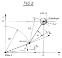
- Figure 2
- is a schematic diagram in which the kinematics of the device of Figure 1 is projected onto a plane perpendicular to the axes of rotation;
- Figure 3
- is a simplified schematic diagram, in which in addition to the representation of Figure 2, the button deflection is taken into account;
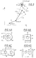
- Figure 4a-d
- shows four calibration bodies that can be used to determine the main dimensions of the coordinate measuring machine according to FIG. 1; and
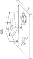
- Figure 5
- shows a perspective view of a base plate on which the calibration body required for the calibration of all dimensions, inclinations, deformations etc. are applied.
Das in Figur 1 schematisch gezeichnete Koordinatenmeßgerät besitzt eine als vertikale z-Führung ausgebildete Säule (1), an der ein Träger (4) mit Hilfe eines Antriebs (2) verschieblich gelagert ist. Die vertikale z-Position kann über einen Maßstab (3) photoelektrisch ausgelesen werden.The coordinate measuring device shown schematically in FIG. 1 has a column (1) designed as a vertical z-guide, on which a support (4) is displaceably mounted by means of a drive (2). The vertical z position can be photoelectrically read out on a scale (3).
Am Träger (4) ist die Drehachse (6) befestigt, um die der erste Gelenkarm (5) in der Ebene (x, y) verschwenkt werden kann. Den Schwenkwinkel φ gibt ein ebenfalls photoelektrisch ausgelesener Teilkreis (16) auf der Achse (6) an.The axis of rotation (6) about which the first articulated arm (5) can be pivoted in the plane (x, y) is fastened to the carrier (4). The swivel angle φ is indicated by a partial circle (16) on the axis (6), which is also photoelectrically read.
Am ersten Gelenkarm (5) ist eine zweite zur vertikalen Achse (6) parallele Achse (8) befestigt. An dieser Achse (8) ist ein zweiter Gelenkarm (7) ebenfalls drehbar gelagert. Zur Erfassung der Drehbewegung dieser zweiten Drehachse (8) dient ein Teilkreis (18) in Verbindung mit einem nicht dargestellten photoelektrischen Abtastsystem.A second axis (8) parallel to the vertical axis (6) is fastened to the first articulated arm (5). A second articulated arm (7) is also rotatably mounted on this axis (8). A pitch circle (18) in conjunction with a photoelectric scanning system, not shown, is used to detect the rotational movement of this second rotational axis (8).
Der zweite Gelenkarm (7) bildet gleichzeitig den Träger für einen Taster (10), der über ein Federparallelogramm mit den beiden gelenkigen Schenkeln (9a, 9b), am Träger (4) angelenkt ist. Über das Federparallelogramm (9a/9b) ist der Taster (10) in der Vertikalen beweglich. Die Auslenkung w des Federparallelogramms wird über ein Meßsystem (23), beispielsweise ein Induktiv-Meßsystem erfaßt und über einen Verstärker (15) dem Motor (2) weitergemeldet, der größere Auslenkung des Parallelogramms durch Nachfahren des Trägers (4) ausregelt.The second articulated arm (7) simultaneously forms the support for a button (10), which is articulated on the support (4) via a spring parallelogram with the two articulated legs (9a, 9b). The button (10) can be moved vertically via the spring parallelogram (9a / 9b). The deflection w of the spring parallelogram is detected by a measuring system (23), for example an inductive measuring system, and is passed on to the motor (2) via an amplifier (15), which compensates for greater deflection of the parallelogram by following the carrier (4).
Der Taststift (11) ist am Taster (10) über ein elastisches Kardan-Gelenk (14) in der Ebene (x, y) auslenkbar. Das Maß der Auslenkung wird über zwei senkrecht zueinander angeordnete Meßsysteme (13a, 13b) erfaßt. Die Position P der Tastkugel (12) ergibt sich somit aus den Meßwerten φ und ψ der Winkelmeßsysteme (16) bzw. (18) in Verbindung mit den Längen R1 und R2 der beiden Gelenkarme (5) und (7) nach folgender Formel, die man anhand der Darstellung nach Figur 2 leicht ableiten kann:![]()
![]()
Während die Parameter R1 und φ0 über einen längeren Zeitraum als konstant angesehen werden können, gilt das nicht für die Parameter R2 und ψ0 sowie für den Tastkugel-Durchmesser dT. Diese unterliegen beim Austausch des Tasters relativ großen Veränderungen.While parameters R1 and φ0 can be regarded as constant over a longer period of time, this does not apply to parameters R2 and ψ0 and for the probe ball diameter dT. These are subject to relatively large changes when the button is replaced.
Wenn man erst einmal davon ausgeht, daß der Taststift (11) starr am Taster befestigt ist und in der Ebene (x, y) nicht ausgelenkt werden kann, dann können die Hauptabmessungen (R1, R2, φ0, ψ0, dT) bestimmt werden, indem in einem Kalibriervorgang die Konturen eines der in den Figuren 4a-d dargestellten Kalibriernormale abgefahren werden, die in der Projektion auf eine Ebene einfache geometrische Figuren darstellen.If you first assume that the stylus (11) is rigidly attached to the button and cannot be deflected in the plane (x, y), then the main dimensions (R1, R2, φ0, ψ0, dT) can be determined, by tracing the contours of one of the calibration standards shown in FIGS. 4a-d in a calibration process, which represent simple geometric figures when projected onto a plane.
Beispielsweise wird die Tastkugel (12) nacheinander jeweils im gleichen Drehsinn an der Innenkontur (32) und der Außenkontur (33) des in Figur 6a dargestellten Lehrrings (31) entlang geführt, deren Durchmesser D1 und D2 hochgenau bekannt ist. Hierbei wird eine größere Anzahl von jeweils z.B. 100 - 200 Meßwerten für die Drehwinkel φ und ψ erzeugt. Diese Meßwerte müssen folgenden Gleichungen im Zusammenhang mit Gleichung (1), (2) genügen:
Eine ähnliches Gleichungssystem läßt sich aufstellen, wenn man als Kalibrierkörper den in Figur 4b dargestellten Quader benutzt, dessen Seitenlänge (S) sehr genau bekannt ist, und der eine zentrische Bohrung mit genau bekanntem Durchmesser D3 besitzt. Auch hier erhält man durch Abfahren der Innenkontur (36) der Bohrung und der Außenkontur (35) des Quaders eine Vielzahl von Meßwerten, die zu den Abmessungen des Kalibrierkörpers in Beziehung gesetzt werden können. Auch hier geht der Tastkugel-Durchmesser beim Abfahren der Außenkontur (35) des Quaders und der Innenkontur (36) der Bohrung jeweils mit unterschiedlichen Vorzeichen in die Meßergebnisse ein.A similar system of equations can be set up if the cuboid shown in FIG. 4b is used as the calibration body, the side length (S) of which is very precisely known and which has a central bore with a precisely known diameter D3. Here too, a large number of measured values are obtained by traversing the inner contour (36) of the bore and the outer contour (35) of the cuboid, which can be related to the dimensions of the calibration body. Here, too, the probe ball diameter enters the measurement results with different signs when the outer contour (35) of the cuboid and the inner contour (36) of the bore are traversed.
Anders ist das bei dem in Figur 4c dargestellten Kalibrierkörpers in Form eines Quaders (37) mit zwei Bohrungen (38) und (39) gleichen Durchmessers. Beim Abfahren dieser Bohrungen geht der Tastkugel-Durchmesser mit gleichem Vorzeichen in die Meßergebnisse ein. Allerdings ist der feste Abstand (A) der beiden Bohrungen (38) und (39) zueinander unabhängig vom Durchmesser der Tastkugel bestimmbar, d.h. der Tastkugel-Durchmesser geht in diesen Abstand mit dem Gewicht Null ein.The situation is different in the case of the calibration body shown in FIG. 4c in the form of a cuboid (37) with two bores (38) and (39) of the same diameter. When traversing these bores, the probe ball diameter is included in the measurement results with the same sign. However, the fixed distance (A) between the two bores (38) and (39) can be determined independently of the diameter of the probe ball, i.e. the probe ball diameter enters this distance with a weight of zero.
Eine weitere Möglichkeit zur Kalibrierung der Hauptabmessungen bietet der in Figur 4d dargestellte Kalibrierkörper. Er besitzt die Form eines Quaders (40), wobei die beiden gegenüberliegenden Seiten (41/42) und (44/43) stark unterschiedliche Abstände A1 und A2 besitzen. Der Ansatz für die Gleichungssysteme, die im Zuge des Kalibriervorganges zu lösen wären, sieht folgendermaßen aus:
Auch hier werden durch Abfahren der gegenüberliegenden Seiten (41/42) und (43/44) des Quaders eine Vielzahl von Meßwerten generiert, über die sich die Hauptabmessungen zurückrechnen lassen. Wie man sieht, geht hier der Tastkugel-Durchmesser im Vergleich zu den übrigen Hauptabmessungen mit sehr unterschiedlichem Gewicht ein, je nachdem ob der Abstand A2 der Seiten (43) und (44) oder der Abstand A1 der Seiten (41) und (42) gemessen wird.Here too, a large number of measured values are generated by traversing the opposite sides (41/42) and (43/44) of the cuboid, by means of which the main dimensions can be calculated back. As you can see, the probe ball diameter has a very different weight compared to the other main dimensions, depending on whether the distance A2 of the sides (43) and (44) or the distance A1 of the sides (41) and (42) is measured.
Für den Fall, daß an dem Gerät wie in Figur 1 dargestellt ein Taster mit auslenkbarem Taststift (11) befestigt sind, sind in einem weiteren Kalibrierschritt die Eigenschaften des messenden Tastsystems zu bestimmen, indem die räumlichen Verlagerungen des Gelenkarms mit den Taster-Auslenkungen u und v selbst in Beziehung gesetzt werden. Denn der Auslenk-Vektor v in der x-y-Ebene verändert die aktuellen Hauptabmessungen R2 und ψ0 des Gelenkarms. Dieser Sachverhalt wird anhand von Fig. 3 deutlich. Im einfachsten Falle, d.h. wenn die Meßsysteme, die die Taster-Auslenkung u und v messen, parallel bzw. senkrecht zu dem Gelenkarm (7) ausgerichtet sind, ergeben sich die Änderungen von R2 und ψ aus den Signalen u und v gemäß folgender Beziehung:![]()
![]()
Führt man die anfangs beschriebene Bestimmung der Hauptabmessungen (R1, R2, φ0, ψ0, dT) nicht wie beschrieben mit einem starren Taster, sondern mit einem Taster mit auslenkbarem Taststift durch, dann sind die Gleichungen Nr. (1) und (2) zu ergänzen, indem R2 und ψ aus Gleichung (1) und (2) jeweils durch ![]()
![]()


![]()
![]()
Die Bestimmung der Hauptabmessungen und die Bestimmung der Koeffizienten der Taster-Auslenkung erfolgt zweckmäßig nach einem iterativen Verfahren, wobei die an einem der Kalibriernormale nach Figur 4a-d ermittelten und gespeicherten Meßwerte und die beim Antasten z.B. einer Würfelecke mit variabler Auslenkung gewonnenen Meßwerte mehrfach hintereinander benutzt werden, um die Gleichungen z.B. (3) und (4) in Verbindung mit (9) und (10) sowie (11) und (12) zu lösen. Man kommt hier nach ca. vier Iterationsschritten zu sehr genauen Werten für die Taster-Koeffizienten (a1, a2) und die Hauptabmessungen (R1, R2, φ0, ψ0, dT).The determination of the main dimensions and the determination of the coefficients of the stylus deflection is expediently carried out according to an iterative process, the one on the Calibration standards according to FIGS. 4a-d determined and stored measurement values and the measurement values obtained when probing, for example, a cube corner with variable deflection, are used several times in succession to equations (3) and (4) in conjunction with (9) and (10) and ( 11) and (12) to solve. After approx. Four iteration steps, you get very precise values for the feeler coefficients (a1, a2) and the main dimensions (R1, R2, φ0, ψ0, dT).
Da die Taster-Koeffizienten in gewissem Ausmaße auch von der Winkelstellung der Gelenkarme (5) und (7), d.h. vom Winkel abhängen können, empfiehlt es sich, die vorgenannten Messungen in mindestens zwei ausgezeichneten Gelenklagen auszuführen, bei denen der Gelenkarm einmal gefaltet und einmal gestreckt ist, wie das anhand von Figur 5 verdeutlicht ist. Dort sind auf der Grundplatte (50) zwei Kugeltripel (51) und (52) an verschiedenen Stellen montiert, in die jeweils mit gefaltetem und gestrecktem Gelenkarm eingetastet werden kann.Since the feeler coefficients also depend to a certain extent on the angular position of the articulated arms (5) and (7), i.e. depend on the angle, it is advisable to carry out the aforementioned measurements in at least two excellent joint positions, in which the articulated arm is folded and stretched once, as is illustrated by FIG. 5. There, on the base plate (50), two triple balls (51) and (52) are mounted at different points, into which each can be inserted with the folded and extended articulated arm.
Die Kalibrierung der Taster-Auslenkung w in z-Richtung, d.h. im wesentlichen die Bestimmung der Linearität des Meßsystems (23) in Figur 1 kann sehr einfach erfolgen, indem der Motor (2) bei festgehaltenem Taster (11) innerhalb des zulässigen Meßbereiches des Meßsystems (23) verfahren wird, d.h. der Schlitten (4) eine Kalibrierfahrt macht und die Meßwerte des z-Meßsystems (3) genutzt werden, um die Signale des Meßwertgebers (23) zu kalibrieren.The calibration of the stylus deflection w in the z direction, i.e. Essentially, the linearity of the measuring system (23) in FIG. 1 can be determined very simply by moving the motor (2) with the button (11) held within the permissible measuring range of the measuring system (23), i.e. the carriage (4) makes a calibration run and the measured values of the z-measuring system (3) are used to calibrate the signals of the measured value transmitter (23).
Bisher wurde davon ausgegangen, daß die beiden Drehachsen (6) und (8) zueinander und zur z-Führung (1) exakt parallel sind. Diese Bedingung ist mit vertretbarem konstruktiven und fertigungstechnischen Aufwand nicht immer einzuhalten.So far it has been assumed that the two axes of rotation (6) and (8) are exactly parallel to each other and to the z-guide (1). This condition cannot always be met with justifiable constructional and manufacturing expenditure.
In der Regel ist das Gerät mehr oder weniger verformt, wie das in Fig. 1A überhöht dargestellt ist.As a rule, the device is more or less deformed, as is shown exaggerated in FIG. 1A.
Zur Ermittlung der Unparallelität der beiden Drehachsen (6) und (8) kann eine Ebene oder eine Gerade, beispielsweise das in Figur 5 auf der Grundplatte (50) durch eine Nut (57) verkörperte Lineal in den beiden strichpunktiert gezeichneten Gelenklagen abgefahren werden. Aus den Differenzen der Meßwerte in den beiden Gelenklagen wird die Schiefstellung der beiden Achsen (6) und (8) zueinander ermittelt, wobei diese Schiefstellung sowohl durch die Montage der Achsen bedingt sein kann, aber auch durch elastische Verformung aufgrund der Eigengewichte der Gelenkarme (5) und (7).To determine the non-parallelism of the two axes of rotation (6) and (8), a plane or a straight line, for example that in FIG Figure 5 on the base plate (50) by a groove (57) ruler embodied in the two dash-dotted joint positions. The misalignment of the two axes (6) and (8) relative to one another is determined from the differences in the measured values in the two joint positions, whereby this misalignment can be caused both by the assembly of the axes but also by elastic deformation due to the dead weights of the articulated arms ( ) and (7).
Um die elastischen Verformungen separat zu erfassen, wird ein definiertes Kalibriernormal wie beispielsweise der Mantel des in Figur 5 mit (54) bezeichneten Zylinders mit dem Radius R und den Achsenkoordinaten Xm und Ym bei geklemmter z-Achse, d.h. bei blockiertem Motor (2) mit schwankender vertikaler Auslenkung und/oder Betätigungskraft Fv abgefahren. Anstelle des vertikal stehenden Zylinders kann selbstverständlich auch ein anderes Kalibriernormal mit senkrechten Flächen, beispielsweise ein Quader oder sonstiges prismatisches Teil verwendet werden. Die so erhaltenen Meßwerte sind untereinander und mit den übrigen Meßwerten der Kalibrierung in Beziehung zu setzen und die Korrektur-Parameter (C1) und (C2) für die Verformung können dann aus folgenden Gleichungen bestimmt werden:

Während wie vorstehend ausgeführt die Kalibrierung der Hauptabmessungen (R1, R2, φ0, ψ0, dT) sowie der Taster-Parameter (a1) und (a2) relativ häufig, beispielsweise nach jedem Tasterwechsel erforderlich ist, brauchen die Biegeparameter und die Schiefstellung der Achsen nur einmal nach der Fertigstellung des Koordinatenmeßgerätes ermittelt werden. Dennoch ist es zweckmäßig, alle für die Kalibrierung erforderlichen Kalibriernormale auf eine gemeinsame Platte zu montieren, wie das in Figur 5 dargestellt ist. Es können dann einzelne oder alle Kalibrierschritte nach Auflegen der Platte (50) auf den Meßtisch des Koordinatenmeßgerätes durchgeführt werden. Dabei sieht der Ablauf so aus, daß beispielsweise auf dem an das Koordinatenmeßgerät angeschlossenen Rechner der Kalibriermodus aufgerufen wird, woraufhin der Rechner die Bedienperson auffordert, die Platte aufzulegen und in die darauf angeordneten Kalibrierkörper (51, 52) einzutasten bzw. die Konturen (53a, 53b, 54, 56) wie vorstehend beschrieben abzufahren. Aus den Meßwerten berechnet der Rechner dann die Kalibrierdaten und speichert diese für den eigentlichen Meßprozeß an den zu vermessenden Werkstücken mit unbekannten Geometrie-Abweichungen.While, as stated above, the calibration of the main dimensions (R1, R2, φ0, ψ0, dT) and the button parameters (a1) and (a2) is relatively common, e.g. after each button change, the bending parameters and the misalignment of the axes only need be determined once after the completion of the coordinate measuring machine. Nevertheless, it is expedient to mount all calibration standards required for the calibration on a common plate, as shown in FIG. 5. Individual or all calibration steps can then be carried out after placing the plate (50) on the measuring table of the coordinate measuring machine. The process is such that, for example, the calibration mode is called up on the computer connected to the coordinate measuring machine, whereupon the computer prompts the operator to place the plate and to insert it into the calibration bodies (51, 52) arranged thereon or to insert the contours (53a, 53b, 54, 56) as described above. The computer then calculates the measured values Calibration data and saves them for the actual measuring process on the workpieces to be measured with unknown geometry deviations.
Claims (15)
Applications Claiming Priority (2)
| Application Number | Priority Date | Filing Date | Title |
|---|---|---|---|
| DE4434014A DE4434014A1 (en) | 1994-09-23 | 1994-09-23 | Procedure for the calibration of a coordinate measuring machine with two rotary axes |
| DE4434014 | 1994-09-23 |
Publications (3)
| Publication Number | Publication Date |
|---|---|
| EP0703430A2 true EP0703430A2 (en) | 1996-03-27 |
| EP0703430A3 EP0703430A3 (en) | 1997-05-28 |
| EP0703430B1 EP0703430B1 (en) | 2001-07-25 |
Family
ID=6529011
Family Applications (1)
| Application Number | Title | Priority Date | Filing Date |
|---|---|---|---|
| EP95114032A Expired - Lifetime EP0703430B1 (en) | 1994-09-23 | 1995-09-07 | Procedure to calibrate a coordinate-measuring machine with two rotational axes |
Country Status (5)
| Country | Link |
|---|---|
| US (1) | US5649368A (en) |
| EP (1) | EP0703430B1 (en) |
| JP (1) | JP3679472B2 (en) |
| DE (2) | DE4434014A1 (en) |
| ES (1) | ES2161814T3 (en) |
Cited By (3)
| Publication number | Priority date | Publication date | Assignee | Title |
|---|---|---|---|---|
| WO2007031070A1 (en) * | 2005-09-15 | 2007-03-22 | Johannes Jeromin | Calibrating gauge for calibrating a vernier caliper |
| CN111771099A (en) * | 2018-02-26 | 2020-10-13 | 瑞尼斯豪公司 | Coordinate positioning machine |
| US11566889B2 (en) * | 2018-09-06 | 2023-01-31 | Tesa Sarl | Portable measuring device with autocalibration and autoconfiguration |
Families Citing this family (15)
| Publication number | Priority date | Publication date | Assignee | Title |
|---|---|---|---|---|
| DE19738099A1 (en) * | 1997-09-01 | 1999-03-04 | Zeiss Carl Fa | Coordinate measuring device or processing machine |
| DE19809589B4 (en) * | 1998-03-06 | 2009-04-02 | Carl Zeiss Industrielle Messtechnik Gmbh | Method for calibrating a probe of a coordinate measuring machine |
| US5929584A (en) * | 1998-04-27 | 1999-07-27 | Pht, Inc. | Tool center point calibration apparatus and method |
| US6112423A (en) * | 1999-01-15 | 2000-09-05 | Brown & Sharpe Manufacturing Co. | Apparatus and method for calibrating a probe assembly of a measuring machine |
| DE10006753A1 (en) * | 2000-02-15 | 2001-08-16 | Zeiss Carl | Rotary swivel device has correction unit which is included in each finite component to correct measurement error due to elastic deformation using mathematical model |
| JP3827549B2 (en) * | 2001-10-04 | 2006-09-27 | 株式会社ミツトヨ | Probe calibration method and calibration program |
| JP3827548B2 (en) * | 2001-10-04 | 2006-09-27 | 株式会社ミツトヨ | Scanning probe calibration method and calibration program |
| GB0326532D0 (en) * | 2003-11-13 | 2003-12-17 | Renishaw Plc | Method of error compensation |
| EP1588855B1 (en) * | 2004-04-20 | 2007-05-30 | GretagMacbeth AG | Device for photoelectric measuring of a measurement document and method for determining coordinates of a selected position on a measurement document with such a measuring device |
| SE531462C2 (en) * | 2005-11-17 | 2009-04-14 | Hexagon Metrology Ab | Adjusting device for a measuring head |
| GB0608235D0 (en) * | 2006-04-26 | 2006-06-07 | Renishaw Plc | Differential calibration |
| JP6108757B2 (en) * | 2012-10-19 | 2017-04-05 | 株式会社ミツトヨ | Calibration method for double cone stylus |
| US10267614B2 (en) * | 2017-04-13 | 2019-04-23 | Sa08700334 | Ultra-light and ultra-accurate portable coordinate measurement machine |
| CN112747702B (en) * | 2020-12-21 | 2022-05-03 | 杭州电子科技大学 | Multifunctional space standard component and calibration method thereof for joint coordinate measuring machine |
| DE102021000470A1 (en) | 2021-01-27 | 2022-07-28 | dim - Dienste industrielle Messtechnik GmbH | Metrological comparison device |
Citations (7)
| Publication number | Priority date | Publication date | Assignee | Title |
|---|---|---|---|---|
| GB1498009A (en) | 1975-05-29 | 1978-01-18 | Newall Eng | Measuring device |
| EP0275428A2 (en) | 1987-01-20 | 1988-07-27 | THE WARNER & SWASEY COMPANY | Method for calibrating a coordinate measuring machine and the like |
| EP0279926A1 (en) | 1987-01-20 | 1988-08-31 | THE WARNER & SWASEY COMPANY | Method for determining position within the measuring volume of a coordinate measuring machine and the like and system therefor |
| EP0304460A1 (en) | 1987-03-06 | 1989-03-01 | Renishaw Plc | Method of and apparatus for calibration of machines. |
| US4891889A (en) | 1987-05-05 | 1990-01-09 | Garda Impianti S.R.L. | Apparatus for measure and/or check the position and orientation of characteristic spots or areas in structures, particularly in motor-vehicle bodies |
| EP0386115A1 (en) | 1987-11-19 | 1990-09-12 | Brown & Sharpe Mfg | Calibration system for coordinate measuring machine. |
| DE4238139A1 (en) | 1992-11-12 | 1994-05-19 | Zeiss Carl Fa | Coordinate measuring device |
Family Cites Families (6)
| Publication number | Priority date | Publication date | Assignee | Title |
|---|---|---|---|---|
| JPS6242010A (en) * | 1985-08-19 | 1987-02-24 | Mitsutoyo Mfg Corp | Reference device for correction of measuring instrument |
| DE3735075A1 (en) * | 1987-10-16 | 1989-04-27 | Zeiss Carl Fa | TEST DEVICE AND METHOD FOR DETERMINING THE MEASURING UNCERTAINTY OF COORDINATE MEASURING DEVICES |
| GB8812579D0 (en) * | 1988-05-27 | 1988-06-29 | Renishaw Plc | Test bar for position determination apparatus |
| EP0362626B1 (en) * | 1988-10-03 | 1993-02-10 | Firma Carl Zeiss | Test body for co-ordinate measuring apparatus |
| US5313410A (en) * | 1991-03-28 | 1994-05-17 | Alpha Q, Inc. | Artifact and method for verifying accuracy of a positioning apparatus |
| US5257460A (en) * | 1991-06-18 | 1993-11-02 | Renishaw Metrology Limited | Machine tool measurement methods |
-
1994
- 1994-09-23 DE DE4434014A patent/DE4434014A1/en not_active Withdrawn
-
1995
- 1995-09-07 ES ES95114032T patent/ES2161814T3/en not_active Expired - Lifetime
- 1995-09-07 EP EP95114032A patent/EP0703430B1/en not_active Expired - Lifetime
- 1995-09-07 DE DE59509442T patent/DE59509442D1/en not_active Expired - Fee Related
- 1995-09-20 JP JP24209795A patent/JP3679472B2/en not_active Expired - Fee Related
- 1995-09-25 US US08/533,273 patent/US5649368A/en not_active Expired - Lifetime
Patent Citations (7)
| Publication number | Priority date | Publication date | Assignee | Title |
|---|---|---|---|---|
| GB1498009A (en) | 1975-05-29 | 1978-01-18 | Newall Eng | Measuring device |
| EP0275428A2 (en) | 1987-01-20 | 1988-07-27 | THE WARNER & SWASEY COMPANY | Method for calibrating a coordinate measuring machine and the like |
| EP0279926A1 (en) | 1987-01-20 | 1988-08-31 | THE WARNER & SWASEY COMPANY | Method for determining position within the measuring volume of a coordinate measuring machine and the like and system therefor |
| EP0304460A1 (en) | 1987-03-06 | 1989-03-01 | Renishaw Plc | Method of and apparatus for calibration of machines. |
| US4891889A (en) | 1987-05-05 | 1990-01-09 | Garda Impianti S.R.L. | Apparatus for measure and/or check the position and orientation of characteristic spots or areas in structures, particularly in motor-vehicle bodies |
| EP0386115A1 (en) | 1987-11-19 | 1990-09-12 | Brown & Sharpe Mfg | Calibration system for coordinate measuring machine. |
| DE4238139A1 (en) | 1992-11-12 | 1994-05-19 | Zeiss Carl Fa | Coordinate measuring device |
Cited By (5)
| Publication number | Priority date | Publication date | Assignee | Title |
|---|---|---|---|---|
| WO2007031070A1 (en) * | 2005-09-15 | 2007-03-22 | Johannes Jeromin | Calibrating gauge for calibrating a vernier caliper |
| CN111771099A (en) * | 2018-02-26 | 2020-10-13 | 瑞尼斯豪公司 | Coordinate positioning machine |
| CN111771099B (en) * | 2018-02-26 | 2022-10-11 | 瑞尼斯豪公司 | Coordinate positioning machine |
| US11964394B2 (en) | 2018-02-26 | 2024-04-23 | Renishaw Plc | Coordinate positioning machine |
| US11566889B2 (en) * | 2018-09-06 | 2023-01-31 | Tesa Sarl | Portable measuring device with autocalibration and autoconfiguration |
Also Published As
| Publication number | Publication date |
|---|---|
| JPH08105702A (en) | 1996-04-23 |
| DE4434014A1 (en) | 1996-03-28 |
| DE59509442D1 (en) | 2001-08-30 |
| ES2161814T3 (en) | 2001-12-16 |
| EP0703430B1 (en) | 2001-07-25 |
| JP3679472B2 (en) | 2005-08-03 |
| US5649368A (en) | 1997-07-22 |
| EP0703430A3 (en) | 1997-05-28 |
Similar Documents
| Publication | Publication Date | Title |
|---|---|---|
| EP0703430B1 (en) | Procedure to calibrate a coordinate-measuring machine with two rotational axes | |
| EP0317967B1 (en) | Rotation-deflection arrangement for the feeler heads of coordinate-measuring devices | |
| EP3049758B1 (en) | Reduction of errors of a rotating device used during the determination of co-ordinates of a workpiece or during the machining of a workpiece | |
| DE60311527T3 (en) | WORKPIECE INSPECTION PROCESS AND DEVICE | |
| DE60019219T2 (en) | METHOD FOR CALIBRATING A SCAN SYSTEM | |
| EP0597299B1 (en) | coordinate measuring machine | |
| EP1342051B1 (en) | Calibration of a measuring sensor on a coordinate measuring machine with a ball, whose center is known | |
| EP2729768B1 (en) | Calibration and operation of rotating devices, in particular for rotating sensing heads and/or probes of coordinate measuring devices | |
| DE602005005839T3 (en) | USE OF SURFACE TESTS | |
| EP0082441A2 (en) | Process and device to evaluate and to correct guide-way faults | |
| EP1593930A1 (en) | Apparatus and method for measuring objects | |
| DE4001433A1 (en) | CORRECTION PROCEDURE FOR COORDINATE MEASURING DEVICES | |
| EP0732563A1 (en) | Coordinate measuring machine incorporating a device for roughness measurement | |
| DE102015205567A1 (en) | Calibration of a rotating device attached to a moving part of a CMM | |
| WO2007107324A1 (en) | Test piece and method for calibrating a coordinate measuring machine | |
| DE10122080A1 (en) | Method for determining properties of a coordinate measuring machine and test object therefor | |
| DE60128574T2 (en) | Method for calibrating a measuring device | |
| DE102017003641B4 (en) | Method for measuring coordinates or properties of a workpiece surface | |
| EP0563058B1 (en) | Method and sensor for the determination of the position of a position-control element relative to a reference body | |
| DE10048096A1 (en) | Swivel unit has optical sensor calibration sensor creates coordinate transformations | |
| DE102015205566A1 (en) | Calibration of a tactile button attached to a moving part of a CMM | |
| EP0169416B1 (en) | Position-sensing probe | |
| DE102019134940A1 (en) | Reference arrangement for a coordinate measuring machine, coordinate measuring machine and method for calibrating a coordinate measuring machine | |
| DE102020103500A1 (en) | Method and device for measuring the roughness and waviness of a surface of a workpiece | |
| DE102015205569A1 (en) | Calibration of a moving part of a CMM or a tactile button attached to it |
Legal Events
| Date | Code | Title | Description |
|---|---|---|---|
| PUAI | Public reference made under article 153(3) epc to a published international application that has entered the european phase |
Free format text: ORIGINAL CODE: 0009012 |
|
| AK | Designated contracting states |
Kind code of ref document: A2 Designated state(s): DE ES FR GB IT SE |
|
| K1C1 | Correction of patent application (title page) published |
Effective date: 19960327 |
|
| PUAL | Search report despatched |
Free format text: ORIGINAL CODE: 0009013 |
|
| AK | Designated contracting states |
Kind code of ref document: A3 Designated state(s): DE ES FR GB IT SE |
|
| 17P | Request for examination filed |
Effective date: 19971025 |
|
| 17Q | First examination report despatched |
Effective date: 20000208 |
|
| GRAG | Despatch of communication of intention to grant |
Free format text: ORIGINAL CODE: EPIDOS AGRA |
|
| GRAG | Despatch of communication of intention to grant |
Free format text: ORIGINAL CODE: EPIDOS AGRA |
|
| GRAH | Despatch of communication of intention to grant a patent |
Free format text: ORIGINAL CODE: EPIDOS IGRA |
|
| RAP1 | Party data changed (applicant data changed or rights of an application transferred) |
Owner name: CARL-ZEISS-STIFTUNG, TRADING AS CARL ZEISS Owner name: CARL ZEISS |
|
| GRAH | Despatch of communication of intention to grant a patent |
Free format text: ORIGINAL CODE: EPIDOS IGRA |
|
| GRAA | (expected) grant |
Free format text: ORIGINAL CODE: 0009210 |
|
| AK | Designated contracting states |
Kind code of ref document: B1 Designated state(s): DE ES FR GB IT SE |
|
| REF | Corresponds to: |
Ref document number: 59509442 Country of ref document: DE Date of ref document: 20010830 |
|
| GBT | Gb: translation of ep patent filed (gb section 77(6)(a)/1977) |
Effective date: 20011016 |
|
| REG | Reference to a national code |
Ref country code: ES Ref legal event code: FG2A Ref document number: 2161814 Country of ref document: ES Kind code of ref document: T3 |
|
| ET | Fr: translation filed | ||
| REG | Reference to a national code |
Ref country code: GB Ref legal event code: IF02 |
|
| PLBE | No opposition filed within time limit |
Free format text: ORIGINAL CODE: 0009261 |
|
| STAA | Information on the status of an ep patent application or granted ep patent |
Free format text: STATUS: NO OPPOSITION FILED WITHIN TIME LIMIT |
|
| 26N | No opposition filed | ||
| REG | Reference to a national code |
Ref country code: GB Ref legal event code: 732E |
|
| PGFP | Annual fee paid to national office [announced via postgrant information from national office to epo] |
Ref country code: IT Payment date: 20080925 Year of fee payment: 14 Ref country code: FR Payment date: 20080912 Year of fee payment: 14 |
|
| PGFP | Annual fee paid to national office [announced via postgrant information from national office to epo] |
Ref country code: GB Payment date: 20080918 Year of fee payment: 14 |
|
| PGFP | Annual fee paid to national office [announced via postgrant information from national office to epo] |
Ref country code: DE Payment date: 20080919 Year of fee payment: 14 |
|
| PGFP | Annual fee paid to national office [announced via postgrant information from national office to epo] |
Ref country code: SE Payment date: 20080912 Year of fee payment: 14 Ref country code: ES Payment date: 20080929 Year of fee payment: 14 |
|
| EUG | Se: european patent has lapsed | ||
| GBPC | Gb: european patent ceased through non-payment of renewal fee |
Effective date: 20090907 |
|
| REG | Reference to a national code |
Ref country code: FR Ref legal event code: ST Effective date: 20100531 |
|
| PG25 | Lapsed in a contracting state [announced via postgrant information from national office to epo] |
Ref country code: FR Free format text: LAPSE BECAUSE OF NON-PAYMENT OF DUE FEES Effective date: 20090930 Ref country code: DE Free format text: LAPSE BECAUSE OF NON-PAYMENT OF DUE FEES Effective date: 20100401 |
|
| PG25 | Lapsed in a contracting state [announced via postgrant information from national office to epo] |
Ref country code: GB Free format text: LAPSE BECAUSE OF NON-PAYMENT OF DUE FEES Effective date: 20090907 |
|
| PG25 | Lapsed in a contracting state [announced via postgrant information from national office to epo] |
Ref country code: IT Free format text: LAPSE BECAUSE OF NON-PAYMENT OF DUE FEES Effective date: 20090907 |
|
| PG25 | Lapsed in a contracting state [announced via postgrant information from national office to epo] |
Ref country code: SE Free format text: LAPSE BECAUSE OF NON-PAYMENT OF DUE FEES Effective date: 20090908 |
|
| REG | Reference to a national code |
Ref country code: ES Ref legal event code: FD2A Effective date: 20110715 |
|
| PG25 | Lapsed in a contracting state [announced via postgrant information from national office to epo] |
Ref country code: ES Free format text: LAPSE BECAUSE OF NON-PAYMENT OF DUE FEES Effective date: 20110705 |
|
| PG25 | Lapsed in a contracting state [announced via postgrant information from national office to epo] |
Ref country code: ES Free format text: LAPSE BECAUSE OF NON-PAYMENT OF DUE FEES Effective date: 20090908 |