EP0680278B1 - Impregnated stent - Google Patents
Impregnated stent Download PDFInfo
- Publication number
- EP0680278B1 EP0680278B1 EP92921719A EP92921719A EP0680278B1 EP 0680278 B1 EP0680278 B1 EP 0680278B1 EP 92921719 A EP92921719 A EP 92921719A EP 92921719 A EP92921719 A EP 92921719A EP 0680278 B1 EP0680278 B1 EP 0680278B1
- Authority
- EP
- European Patent Office
- Prior art keywords
- stent
- wall structure
- endoprosthesis
- cured
- sheath
- Prior art date
- Legal status (The legal status is an assumption and is not a legal conclusion. Google has not performed a legal analysis and makes no representation as to the accuracy of the status listed.)
- Expired - Lifetime
Links
Images


Classifications
-
- A—HUMAN NECESSITIES
- A61—MEDICAL OR VETERINARY SCIENCE; HYGIENE
- A61F—FILTERS IMPLANTABLE INTO BLOOD VESSELS; PROSTHESES; DEVICES PROVIDING PATENCY TO, OR PREVENTING COLLAPSING OF, TUBULAR STRUCTURES OF THE BODY, e.g. STENTS; ORTHOPAEDIC, NURSING OR CONTRACEPTIVE DEVICES; FOMENTATION; TREATMENT OR PROTECTION OF EYES OR EARS; BANDAGES, DRESSINGS OR ABSORBENT PADS; FIRST-AID KITS
- A61F2/00—Filters implantable into blood vessels; Prostheses, i.e. artificial substitutes or replacements for parts of the body; Appliances for connecting them with the body; Devices providing patency to, or preventing collapsing of, tubular structures of the body, e.g. stents
- A61F2/82—Devices providing patency to, or preventing collapsing of, tubular structures of the body, e.g. stents
- A61F2/86—Stents in a form characterised by the wire-like elements; Stents in the form characterised by a net-like or mesh-like structure
- A61F2/90—Stents in a form characterised by the wire-like elements; Stents in the form characterised by a net-like or mesh-like structure characterised by a net-like or mesh-like structure
-
- A—HUMAN NECESSITIES
- A61—MEDICAL OR VETERINARY SCIENCE; HYGIENE
- A61F—FILTERS IMPLANTABLE INTO BLOOD VESSELS; PROSTHESES; DEVICES PROVIDING PATENCY TO, OR PREVENTING COLLAPSING OF, TUBULAR STRUCTURES OF THE BODY, e.g. STENTS; ORTHOPAEDIC, NURSING OR CONTRACEPTIVE DEVICES; FOMENTATION; TREATMENT OR PROTECTION OF EYES OR EARS; BANDAGES, DRESSINGS OR ABSORBENT PADS; FIRST-AID KITS
- A61F2/00—Filters implantable into blood vessels; Prostheses, i.e. artificial substitutes or replacements for parts of the body; Appliances for connecting them with the body; Devices providing patency to, or preventing collapsing of, tubular structures of the body, e.g. stents
- A61F2/95—Instruments specially adapted for placement or removal of stents or stent-grafts
- A61F2/958—Inflatable balloons for placing stents or stent-grafts
-
- A—HUMAN NECESSITIES
- A61—MEDICAL OR VETERINARY SCIENCE; HYGIENE
- A61F—FILTERS IMPLANTABLE INTO BLOOD VESSELS; PROSTHESES; DEVICES PROVIDING PATENCY TO, OR PREVENTING COLLAPSING OF, TUBULAR STRUCTURES OF THE BODY, e.g. STENTS; ORTHOPAEDIC, NURSING OR CONTRACEPTIVE DEVICES; FOMENTATION; TREATMENT OR PROTECTION OF EYES OR EARS; BANDAGES, DRESSINGS OR ABSORBENT PADS; FIRST-AID KITS
- A61F2/00—Filters implantable into blood vessels; Prostheses, i.e. artificial substitutes or replacements for parts of the body; Appliances for connecting them with the body; Devices providing patency to, or preventing collapsing of, tubular structures of the body, e.g. stents
- A61F2/0077—Special surfaces of prostheses, e.g. for improving ingrowth
-
- A—HUMAN NECESSITIES
- A61—MEDICAL OR VETERINARY SCIENCE; HYGIENE
- A61F—FILTERS IMPLANTABLE INTO BLOOD VESSELS; PROSTHESES; DEVICES PROVIDING PATENCY TO, OR PREVENTING COLLAPSING OF, TUBULAR STRUCTURES OF THE BODY, e.g. STENTS; ORTHOPAEDIC, NURSING OR CONTRACEPTIVE DEVICES; FOMENTATION; TREATMENT OR PROTECTION OF EYES OR EARS; BANDAGES, DRESSINGS OR ABSORBENT PADS; FIRST-AID KITS
- A61F2210/00—Particular material properties of prostheses classified in groups A61F2/00 - A61F2/26 or A61F2/82 or A61F9/00 or A61F11/00 or subgroups thereof
- A61F2210/0014—Particular material properties of prostheses classified in groups A61F2/00 - A61F2/26 or A61F2/82 or A61F9/00 or A61F11/00 or subgroups thereof using shape memory or superelastic materials, e.g. nitinol
- A61F2210/0019—Particular material properties of prostheses classified in groups A61F2/00 - A61F2/26 or A61F2/82 or A61F9/00 or A61F11/00 or subgroups thereof using shape memory or superelastic materials, e.g. nitinol operated at only one temperature whilst inside or touching the human body, e.g. constrained in a non-operative shape during surgery, another temperature only occurring before the operation
-
- A—HUMAN NECESSITIES
- A61—MEDICAL OR VETERINARY SCIENCE; HYGIENE
- A61F—FILTERS IMPLANTABLE INTO BLOOD VESSELS; PROSTHESES; DEVICES PROVIDING PATENCY TO, OR PREVENTING COLLAPSING OF, TUBULAR STRUCTURES OF THE BODY, e.g. STENTS; ORTHOPAEDIC, NURSING OR CONTRACEPTIVE DEVICES; FOMENTATION; TREATMENT OR PROTECTION OF EYES OR EARS; BANDAGES, DRESSINGS OR ABSORBENT PADS; FIRST-AID KITS
- A61F2220/00—Fixations or connections for prostheses classified in groups A61F2/00 - A61F2/26 or A61F2/82 or A61F9/00 or A61F11/00 or subgroups thereof
- A61F2220/0025—Connections or couplings between prosthetic parts, e.g. between modular parts; Connecting elements
- A61F2220/005—Connections or couplings between prosthetic parts, e.g. between modular parts; Connecting elements using adhesives
Definitions
- This invention generally relates to a class of endoprostheses known as "stents" and more specifically to the structure and manufacture of such stents and the assembly of such stents into delivery systems.
- stents Certain medical devices, called “stents”, are well known and have a variety of forms.
- United States Letters Patent No. 4,690,684 of September 1, 1987 to McGreevy et al for a "Meltable Stent for Anastomosis” discloses a solid stent formed of a biologically compatible material, such as frozen blood plasma or the like.
- a solid stent of this type may be inserted into opposed ends of a ruptured vessel to support the separated vessel walls while the ends are bonded together. The heat from the bonding operation and the body eventually melt the stent and clear the vessel.
- a stent that constitutes an endoprosthesis usually comprises a tubular structure that expands radially to be implanted into the tissue surrounding a "vessel" thereby to maintain its patency. It is well known that stents may be utilized in body canals, blood vessels, ducts and other body passageways, and the term “vessel” is meant to include all such passageways.
- a stent delivery system includes the stent and some means for positioning and fixing the stent in place.
- the stent delivery system includes a catheter that supports the stent in a compacted form for transport to a site of implantation. Means integral with or ancillary to the catheter then expand the stent radially into the vessel walls to be implanted at the selected site. After the catheter is removed, the stent retains an expanded shape to keep the vessel walls from closing.
- Stent delivery systems must conform to several important criteria. First, it is important to keep the cross-sectional dimension of the delivery system to a minimum, so the stent must be capable of compaction against a delivery device, such as a catheter. Second, the delivery system must facilitate the deployment of the stent into contact with the vessel walls once it is located in a body. Third, the stent delivery system must easily disengage from the stent after the stent is deployed. Fourth, the procedure for removing the delivery system from the body must be straightforward. Fifth, the delivery system must operate reliably.
- the stent comprises a tubular structure that is knitted from metal or plastic filaments in loosely interlocked loops.
- a stent delivery system includes a balloon catheter and a coaxial sheath.
- the balloon catheter supports the compacted stent during its transport to a site within the body.
- the sheath covers the stent to prevent premature stent expansion and to facilitate the transfer of the stent through various passages in the body.
- a physician properly locates the stent, and then moves the sheath axially with respect to the catheter thereby to expose the stent.
- the physician operates a balloon pumping system to expand the balloon catheter and move the stent into a final configuration in contact with tissue surrounding the stent.
- the stent expands radially, the filament material undergoes a plastic deformation. Consequently, the stent retains its new expanded shape.
- the balloon subsequently deflates, it is free of the expanded stent, so the catheter, sheath and remainder of the delivery system can be withdrawn from the patient.
- EP-A-0 218 203 discloses an encapsulated expandable closing device, such a continence device in the form of a block of resilient foam material capable of being collapsed into a small volume condition and encapsulated with gelatin that surrounds the compressed foam material.
- the gelatin maintains the small volume condition during placement in a desired body orifice.
- the gelatine capsule then dissolves in the presence of body warmth and moisture to enable the compressed soft foam material to expand to a predetermined size and shape for blockage and for temporary retention of gastrointestinal contents in the body orifice.
- the overall diameter and flexibility of a stent and its delivery system determine the range of vessels that can receive a stent. It is important that any stent structure should have as small an overall diameter as possible. The smaller the diameter, the greater the range of vessels for which the endoprosthesis becomes viable. That range of vessels is limited with prior art structures, particularly by a protective sheath or the like that surrounds a stent and has two functions. First, the protective sheath provides a smooth surface over the stent to facilitate its transport through the body with minimal trauma. Second, the protective sheath prevents the stent from expanding prematurely. The second function determines the wall thickness of a sheath or like structure and with it the overall diameter of the stent delivery system.
- the wall must be sufficiently thick to provide the strength necessary to restrain the stent. This thickness is greater than the wall thickness required by the first function. For a given diameter stent, the overall diameter of the stent and the sheath or the like can exceed a minimal diameter. It is this characteristic that prevents the introduction of prior art stents into smaller vessels.
- Another object of this invention is to provide an improved stent structure that is capable of minimising the overall diameter of the stent and the apparatus for delivering the stent to a vessel.
- Yet another object of this invention is to provide an improved stent structure that enables the placement of the stent in vessels that are smaller than those that could receive prior art stents.
- the present invention is directed to a tubular endoprosthesis of the general type disclosed in US-A-4,922,905 and as defined in the precharacterising clause of claim 1.
- tubular endoprosthesis as defined in the characterising clause of claim 1.
- the prosthesis embodying this invention consist of a stent assembly that comprises a compact mesh in a cylindrical form.
- the mesh can expand into a cylindrical mesh stent that engages the tissue walls surrounding a vessel.
- a cured dissolvable material impregnates the mesh and contains the mesh in its compact form during placement. The cured material dissolves when the stent is in position in the body thereby to free the mesh and enable its expansion into a final form contacting the ⁇ issue surrounding the vessel.
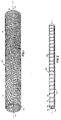
- FIG. 1 discloses one embodiment of tubular endoprothesis, or a stent 10, in expanded form and constructed in accordance with the disclosure of the previously identified United States Letters Patent No. 4,922,905.
- the stent 10 comprises a single filament 11 that is knitted into a mesh cylinder 12 extending coaxially with an axis 13 and comprising a fabric of loosely interlocked filament loops that form the wall of the cylinder 12.
- the filament can be selected from two groups of materials depending upon the ultimate characteristics of the stent 10.
- the filament 11 should be formed of a biocompatible material.
- the structure When expanded to a final form as shown in FIG. 1, the structure should be resistant to subsequent deformation.
- these materials normally are taken from a group of shape memory metals that maintain the stent in an expanded form.
- the material preferably is radiopaque.
- a self-expanding material such as a super elastic material is selected so that compaction produces internal restoring forces within the material.
- Nitinol is an example of such a super elastic material that is particularly adapted for self-expanding stents.
- the stent 10 is self-expanding, it will be necessary to contain such self-expanding stents in compact form. The stent 10 will return to the shape shown in FIG.1 when it is freed from any containment.
- the stent 10 may be comprised of a material from a group of plastic deformable materials that include stainless steel and tantalum.
- the stent 10 in FIG. 1 is compacted into a stent assembly 20 as shown in FIG. 2.
- compaction can produce a reduction in the overall radius of the stent 10 by a 10:1 with about a 30% increase in the overall length of the stent 10.
- the stent assembly 20 also includes a cured, dissolvable material that readily shifts between liquid and solid phases at a melting temperature in the range of 30°C to 40°C. This material impregnates the interstices of the mesh stent 10 and has sufficient strength to contain the stent 10 in its compact form.
- Gelatin is particularly adapted for use in accordance with this invention as it transforms from a liquid form on cooling into a cured, solid mass.
- the mass has sufficient strength to contain the stent 10 in its compact form, even when the stent 10 is formed of a self-expanding material.
- Gelatin also has the property of liquefying when heated above some predetermined temperature that is normally less than 37°C.
- certain enzymes such as those found in the body, will attack the gelatin and cause it to lose its strength and viscosity.
- the rate of thermal decomposition of gelatin depends upon the type and quality of the gelatin, the temperature of the gelatin and the nature of any enzymes that may attack the solution. All these parameters can be controlled by the selection of gelatins with particular properties. Particularly, it has been found that Vee Gee Extra Fine 100 Bloom Type A gelatin or Vee Gee 100 Bloom Type B gelatin from the Vyse Gelatin Company produce satisfactory gelatins for impregnating a mesh stent.
- the stent assembly 20 may be constructed with pure gelatin or like dissolvable materials that only contain the stent, other constituents can be added for producing other functions.
- the gelatin or other material could entrain any of a number of encapsulated medicines for a timed release into the body as the material dissolves, particularly if a gelatin is designed to dissolve over a longer time period.
- the axial distribution could be used to control the physical profile of a the stent as it expands.
- a stent When a stent is impregnated with a cured gelatin or other material, it becomes rigid. This rigidity impairs the ability of the stent assembly 20 to pass through a tortious path to a vessel.
- a helical groove 22 in the outer cylindrical surface 23 of the stent assembly 20 facilitates bending of the stent assembly 20.
- the gelatin 21 could be located at discrete, separated axial positions along the length of the compact stent and achieve the same general results while also improving flexibility.
- a groove could be formed on an inner cylindrical surface 24 of the stent assembly 20.
- the exact method of manufacture of a given stent assembly in accordance with this invention depends upon several factors. Two major factors are the final application for the stent and whether the stent 10 is formed of a self-expanding material or an expansible material that requires some external force to expand it.
- the manufacturing process begins with a selection of a stent 10 shown in FIG. 3A and represented by steps 41 and 42 in FIG. 4. That is, in accordance with step 41 the stent 10 in FIG. 3A would be formed of an expansible plastic deformable material, such as stainless steel or tantalum. In step 42 the stent would be selected from any of the self-expanding super elastic alloys for stent material such as Nitinol.
- a next step is optional and dependent upon the end application.
- step 43 it is possible to select a mandrel 30 in FIG. 3B. If the stent 10 is already in a compact form, it may be possible that no mandrel is required at all. In other applications, the mandrel 30 might become an integral part of the final stent assembly 20. In such an application the mandrel might constitute a balloon portion of a balloon catheter. In still other applications, the mandrel 30 might be used only for manufacture and then removed from the final stent assembly 20. If the stent is to be manufactured as a self-expanding stent, the mandrel 30 might be selected as a tube insert formed of an extruded polymer material as shown in step 44.
- Step 45 in FIG.4, is also an optional step in which radiopaque markers 31 and 32 are attached to the mandrel 30, as shown in FIG. 3C.
- the spacing between the markers 31 and 32 corresponds to the axial length of the stent 10 of FIG. 3A in its compact form.
- step 46 the stent 10, if in an expanded form, is compacted onto the mandrel 30 by applying tension in an axial direction simultaneously with radial compression so the stent will have a low profile that facilitates its introduction into a body passageway.
- a supplementary mandrel 33 can be positioned in the mandrel 30 for added support.
- a filament 34 may be wrapped around the compacted stent 10 and tied to the mandrel 30 in step 47. This filament 34 contains the stent 10 in its compact form for subsequent processing.
- the filament 34 can comprise any number of materials that contain the stent in its compact form during the processing and do not adhere to the gelatin or other material that impregnates the stent.
- Elastic filaments containing polymeric silicons are preferred because of advantages in subsequent processing steps; Silastic® filaments are examples.
- step 50 liquid gelatin 35, or a similar liquid, is poured from a container 36 onto the stent 10 while the entire assembly rotates on the mandrel 33.
- the liquid 35 fills the spaces formed by the interstices of the mesh and the spaces between the filament 34.
- the material 35 fills the interstices of the compact stent 10, it cools and begins to form a semi-rigid mass.
- step 51 excess material 35 is wiped from the stent 10 and the material 35 cures to produce an interdisposed restraining structure for maintaining the stent in its compact form.
- the material 35 cures, it is possible to remove the filament 34 from the assembly. If this is an elastic material, then applying tension to the filament 34 reduces its diameter slightly and facilitates its removal from the cured material 35. This leaves the helical groove 22 shown in FIG. 3F that improves the overall flexibility of the stent assembly 20.
- the stent 10 remains in a compact form because the cured dissolvable material 35, such as cured gelatin, has sufficient strength to contain the stent 10.
- step 53 is used to install various end and tip bushings as needed on the mandrel 30, and step 54 to affix a positioning device in the end bushing and to locate the stent assembly in a sheath.
- step 55 is used to remove the mandrel 30 if that mandrel is not required in the final assembly. If that mandrel is formed of a Silastic material, its removal is facilitated as tensioning the material in an axial direction reduces its diameter and facilitates its removal from a central aperture along the axis of the assembly. In that case the structure that results from the manufacture appears as the structure in FIG. 2 that is adapted for later installation on an expansion or other device.
- Step 56 represents procedures for finally positioning the stent assembly 20 on a support device.
- FIG. 5 discloses an embodiment of a stent delivery system that is adapted for positioning a self-expanding stent assembly in a vessel.
- the impregnated stent assembly 20 is mounted on a tubular mandrel 30 with markers 31 and 32.
- a central aperture 60 through the tubular mandrel 30 enables the tube to slide over a guide wire 61.
- a tip bushing 62 includes a hollow shank portion 63 and an end portion 64.
- the shank portion 63 has an outer diameter that interfits with a distal end of a sheath 65 and a center aperture 66 that fits snugly over the tubular mandrel 30.
- a central aperture 67 in the tip 61 aligns with the central aperture 60 thereby to allow the guide wire 61 to pass through the tip 62.
- the proximal end of the sheath 65 terminates at a steering bushing 70 that includes a shank portion 71 that receives the proximal end of the sheath 65 and a head portion 72.
- the steering bushing 70 has a central aperture or through hole 73 that allows the passage of a pusher tube 74 therethrough.
- the pusher tube 74 terminates in a handle or thumb pad 75.
- the tube 74 engages an end bushing 80.
- the end bushing 80 has a proximal shank portion 81 and a distal head portion 82.
- An aperture 83 is coextensive with at least the head portion 82 and receives the proximal end of the mandrel 30.
- the shank portion 81 has another aperture 84 that receives the distal end of the pusher tube 74.
- the diameter of the head portion 82 is selected so it can slide freely within the sheath 65.
- the guide wire 61 will be located in a body as shown in FIG. 6. Then the assembly, shown in FIG. 5, can be slid over the guide wire 61.
- the tip bushing 62 seals the end of the stent delivery system and prevents any body fluids 85 from reaching the stent assembly 20 as the stent assembly passes through various vessels 86 in tissue 87.
- Radiographic or fluoroscopic techniques provide final location information by imaging the markers 31 and 32. The physician can then withdraw the steering bushing 70 toward the pusher tube 74 thereby withdrawing the sheath 65 from the tip bushing 62. This exposes the stent assembly 20 to the body fluids. The fluids, through their temperature and constituents, dissolve the material 21, such as gelatin, over a controlled time interval.
- the stent 10 has a much larger diameter than the overall diameter of the stent delivery system including the tip bushing 62, so the entire stent delivery system can be withdrawn along the guide wire 61 and removed from the body.
- FIG. 7 depicts an embodiment in which a balloon catheter 91 supports a stent assembly 20 as an example of a stent that requires an external force to expand it.
- a balloon 92 could constitute a mandrel 30 in FIG. 3B to support the stent assembly 20.
- the remaining portions of the balloon catheter include a central supporting catheter 93 typically with two lumens.
- a central lumen 94 receives a guide wire 61.
- a second lumen 95 provides a passage for allowing a balloon control system 96 to inflate and deflate the balloon 92.
- FIG. 7 also includes the markers 31 and 32 at the opposite ends of the stent assembly 20.
- the delivery system in FIG. 7 may or may not be constructed with a protective sheath. If the dissolvable material is selected properly, it is possible to introduce the stent assembly into the body without any protective sheath. In such an embodiment, the body fluids and the temperature will produce slow initial dissolution at the circumferential surface 97 of the stent 10. This surface is relatively smooth and the slight melting produces a lubricating function thereby to allow the structure to transfer through the vessels with minimal trauma.
- a sheath if used, is withdrawn.
- the stent 10 will be freed from the balloon catheter and pumping the balloon catheter expands the balloon 92 thereby forcing the stent 10 into its final position.
- the balloon control system 96 deflates the balloon 92 and the entire balloon catheter 91 can be withdrawn along the guide wire 61.
- this invention provides an improved stent assembly that uses a cured, dissolvable material to retain a stent in a compact form until it is properly oriented within a vessel.
- Specific materials for containing the stent are disclosed. Others may also exist or be developed that will shift from a liquid state to a solid state at room temperature and shift back to a liquid state at a controlled rate at temperatures normally encountered in the body. The same material can be utilized with both self-expanding stents and stents that require some external means for expansion.
- a stent may be formed in compact form or be compacted from a final form.
- Different stents can comprise a wide variety of materials or combinations of materials.
- the stents may be knitted, woven, formed, rolled, extruded or machined.
- the term "mesh" is exemplary only.
- Some delivery systems may include external sheaths around the stent assembly; others may not. When a sheath is desirable, the sheath can be very thin because it only needs to provide a smooth exterior surface. There is no requirement for the sheath having sufficient strength to contain a stent. As a result, the overall size of a stent delivery system decreases so it can transfer a stent assembly into smaller vessels.
- Other configurations of catheters and delivery systems could be substituted for either self-expanding stents or stents requiring some external expansion means.
Abstract
Description
Claims (9)
- A tubular endoprosthesis (20) for inserting in a lumen of a body comprising:an expansible wall structure (12) formed of a filament material (11) said wall structure having a first relatively small diameter form for low profile introduction into the lumen, and being expansible in the lumen to form a wall structure having an expanded profile,
said endoprosthesis being characterised by additionally comprising a cured, solid dissolvable means (21) impregnating said wall structure (12) for containing said wall structure in its first relatively small diameter form, said dissolvable means transforming to a liquid state when said tubular endoprosthesis is in position in the lumen thereby to free said wall structure and enable its expansion in the lumen. - A tubular endoprosthesis as recited in claim 1, wherein said expansible wall structure comprises an open fabric of a filament material and has the capability of expanding radially in the body lumen, said cured dissolvable means, in its solid state, retaining said wall structure in its first relatively small diameter form.
- A tubular endoprosthesis as recited in any of claims 1 and 2, in combination with a delivery system for positioning said tubular endoprosthesis in the body lumen, wherein said delivery system includes a cylindrical sheath (65) for overlying said endoprosthesis, and being retractable from a position overlying said endoprosthesis so as to expose said endoprosthesis and said cured dissolvable means in the body lumen.
- A tubular endoprosthesis as recited in any of claims 1 through 3, wherein said wall structure is formed by a filament material taken from the group of materials consisting of self-expanding, super-elastic materials, including Nitinol.
- A tubular endoprosthesis as recited in claim 3, or claim 3 in combination with claim 4, wherein said delivery system additionally includes:i. support means (30) for carrying said wall structure,ii. distal tip means (62) and proximal bushing means (80) mounted to said support means for preventing axial motion of said wall structure relative to said support means,iii. steering means (74) connected to said proximal bushing means for moving said sheath (65) and contained wall structure to a predetermined position in the body lumen, andiv. means (70) for moving said sheath relative to said steering means to retract said sheath from said wall structure thereby to enable said cured dissolvable means to dissolve and said wall structure to expand in the body lumen.
- A tubular endoprosthesis as recited in any of claims 1 through 3, wherein said wall structure is formed by a filament material (11) taken from the group of materials consisting of plastic deformable materials, including stainless steel and tantalum.
- A tubular endoprosthesis as recited in claim 3, or claim 3 in combination with claim 6, wherein said delivery system additionally includes:i. support means (91) for carrying said wall structure,ii. distal tip means (62) and proximal bushing means (80) mounted to said support means for preventing axial motion of said wall structure relative to said support means,iii. steering means (74) connected to said proximal bushing means for moving said sheath (65) and contained wall structure to a predetermined position in the body lumen,iv. means (70) for moving said sheath relative to said steering means to retract said sheath from said wall structure thereby to enable said cured dissolvable means to dissolve, andv. expansion means (92) for expanding said wall structure in the body lumen.
- A tubular endoprosthesis as recited in any of claims 1 through 7, wherein said cured dissolvable means is formed into discrete axial segments, or is grooved, for improving the flexibility of said tubular endoprosthesis.
- A tubular endoprosthesis as recited in any of claims 1 through 8, wherein said cured dissolvable means entrains a disparate constituent for release into the body as said cured dissolvable means dissolves.
Applications Claiming Priority (3)
| Application Number | Priority Date | Filing Date | Title |
|---|---|---|---|
| US07/773,847 US5234457A (en) | 1991-10-09 | 1991-10-09 | Impregnated stent |
| US773847 | 1991-10-09 | ||
| PCT/US1992/008719 WO1993006781A1 (en) | 1991-10-09 | 1992-10-06 | Impregnated stent |
Publications (3)
| Publication Number | Publication Date |
|---|---|
| EP0680278A4 EP0680278A4 (en) | 1994-10-24 |
| EP0680278A1 EP0680278A1 (en) | 1995-11-08 |
| EP0680278B1 true EP0680278B1 (en) | 1999-01-20 |
Family
ID=25099501
Family Applications (1)
| Application Number | Title | Priority Date | Filing Date |
|---|---|---|---|
| EP92921719A Expired - Lifetime EP0680278B1 (en) | 1991-10-09 | 1992-10-06 | Impregnated stent |
Country Status (6)
| Country | Link |
|---|---|
| US (1) | US5234457A (en) |
| EP (1) | EP0680278B1 (en) |
| JP (1) | JP3600235B2 (en) |
| CA (1) | CA2119371C (en) |
| DE (1) | DE69228260T2 (en) |
| WO (1) | WO1993006781A1 (en) |
Cited By (3)
| Publication number | Priority date | Publication date | Assignee | Title |
|---|---|---|---|---|
| DE102004008459A1 (en) * | 2004-02-17 | 2005-09-01 | Aesculap Ag & Co. Kg | Implant, useful as stents, comprises a fabric and at least a radiopaque marker, which passes in a direction along the implant |
| US7306625B1 (en) | 1999-06-24 | 2007-12-11 | Abbott Laboratories | Balloon expandable stent |
| CN107349038A (en) * | 2017-07-03 | 2017-11-17 | 山东省药学科学院 | A kind of preparation method of vivo inserted support |
Families Citing this family (340)
| Publication number | Priority date | Publication date | Assignee | Title |
|---|---|---|---|---|
| US5843089A (en) * | 1990-12-28 | 1998-12-01 | Boston Scientific Corporation | Stent lining |
| US5439446A (en) * | 1994-06-30 | 1995-08-08 | Boston Scientific Corporation | Stent and therapeutic delivery system |
| US5674192A (en) | 1990-12-28 | 1997-10-07 | Boston Scientific Corporation | Drug delivery |
| US5500013A (en) * | 1991-10-04 | 1996-03-19 | Scimed Life Systems, Inc. | Biodegradable drug delivery vascular stent |
| US5662713A (en) * | 1991-10-09 | 1997-09-02 | Boston Scientific Corporation | Medical stents for body lumens exhibiting peristaltic motion |
| US5876445A (en) * | 1991-10-09 | 1999-03-02 | Boston Scientific Corporation | Medical stents for body lumens exhibiting peristaltic motion |
| US5683366A (en) * | 1992-01-07 | 1997-11-04 | Arthrocare Corporation | System and method for electrosurgical tissue canalization |
| US5405378A (en) | 1992-05-20 | 1995-04-11 | Strecker; Ernst P. | Device with a prosthesis implantable in the body of a patient |
| US6336938B1 (en) | 1992-08-06 | 2002-01-08 | William Cook Europe A/S | Implantable self expanding prosthetic device |
| WO1994003127A1 (en) * | 1992-08-06 | 1994-02-17 | William Cook Europe A/S | A prosthetic device for sustaining a blood-vessel or hollow organ lumen |
| US5707376A (en) * | 1992-08-06 | 1998-01-13 | William Cook Europe A/S | Stent introducer and method of use |
| CA2146156C (en) * | 1992-10-13 | 2004-11-30 | Erik Andersen | Medical stents for body lumens exhibiting peristaltic motion |
| DE59206251D1 (en) * | 1992-10-31 | 1996-06-13 | Schneider Europ Ag | Arrangement for implanting self-expanding endoprostheses |
| ES2059202T3 (en) * | 1992-12-16 | 1994-11-01 | Schneider Europ Ag | DEVICE TO IMPLEMENT A SELF-EXPANDABLE ENDOPROTESIS IN A VESSEL. |
| US5443458A (en) * | 1992-12-22 | 1995-08-22 | Advanced Cardiovascular Systems, Inc. | Multilayered biodegradable stent and method of manufacture |
| US5964744A (en) * | 1993-01-04 | 1999-10-12 | Menlo Care, Inc. | Polymeric medical device systems having shape memory |
| US5599291A (en) * | 1993-01-04 | 1997-02-04 | Menlo Care, Inc. | Softening expanding ureteral stent |
| WO1994023786A1 (en) * | 1993-04-13 | 1994-10-27 | Boston Scientific Corporation | Prosthesis delivery system |
| WO1994023669A1 (en) * | 1993-04-13 | 1994-10-27 | Boston Scientific Corporation | Prosthesis delivery system with dilating tip |
| IT1276342B1 (en) * | 1993-06-04 | 1997-10-30 | Ist Naz Stud Cura Dei Tumori | METAL STENT COVERED WITH BIOCOMPATIBLE POLYMERIC MATERIAL |
| DE4333836C2 (en) * | 1993-10-05 | 1998-07-02 | Angiomed Ag | Device for bridging a bag |
| US5989280A (en) * | 1993-10-22 | 1999-11-23 | Scimed Lifesystems, Inc | Stent delivery apparatus and method |
| ATE288298T1 (en) * | 1993-10-22 | 2005-02-15 | Scimed Life Systems Inc | STENT DELIVERY APPARATUS AND METHOD |
| US5445646A (en) * | 1993-10-22 | 1995-08-29 | Scimed Lifesystems, Inc. | Single layer hydraulic sheath stent delivery apparatus and method |
| US5571135A (en) * | 1993-10-22 | 1996-11-05 | Scimed Life Systems Inc. | Stent delivery apparatus and method |
| US5607444A (en) * | 1993-12-02 | 1997-03-04 | Advanced Cardiovascular Systems, Inc. | Ostial stent for bifurcations |
| JP2703510B2 (en) | 1993-12-28 | 1998-01-26 | アドヴァンスド カーディオヴァスキュラー システムズ インコーポレーテッド | Expandable stent and method of manufacturing the same |
| NL9400436A (en) * | 1994-03-18 | 1995-11-01 | Benedict Marie Doorschodt | Fallopian tube blocking device and blocking assembly. |
| ATE310839T1 (en) * | 1994-04-29 | 2005-12-15 | Scimed Life Systems Inc | STENT WITH COLLAGEN |
| CA2189006A1 (en) * | 1994-04-29 | 1995-11-09 | David L. Sandock | Medical prosthetic stent and method of manufacture |
| US5499995C1 (en) * | 1994-05-25 | 2002-03-12 | Paul S Teirstein | Body passageway closure apparatus and method of use |
| US5857998A (en) | 1994-06-30 | 1999-01-12 | Boston Scientific Corporation | Stent and therapeutic delivery system |
| US6123715A (en) * | 1994-07-08 | 2000-09-26 | Amplatz; Curtis | Method of forming medical devices; intravascular occlusion devices |
| DE4424242A1 (en) * | 1994-07-09 | 1996-01-11 | Ernst Peter Prof Dr M Strecker | Endoprosthesis implantable percutaneously in a patient's body |
| FR2722413B1 (en) * | 1994-07-13 | 1997-02-07 | Marian Devonec | THERAPEUTIC IMPLANT INTENDED FOR THE SELECTIVE CYTOREDUCTIVE TREATMENT OF LIGHT OR NATURAL PATH OBSTRUCTION OF A HUMAN OR ANIMAL BODY |
| US5649977A (en) * | 1994-09-22 | 1997-07-22 | Advanced Cardiovascular Systems, Inc. | Metal reinforced polymer stent |
| US5707385A (en) * | 1994-11-16 | 1998-01-13 | Advanced Cardiovascular Systems, Inc. | Drug loaded elastic membrane and method for delivery |
| US5637113A (en) * | 1994-12-13 | 1997-06-10 | Advanced Cardiovascular Systems, Inc. | Polymer film for wrapping a stent structure |
| EP0810845A2 (en) * | 1995-02-22 | 1997-12-10 | Menlo Care Inc. | Covered expanding mesh stent |
| US5749851A (en) * | 1995-03-02 | 1998-05-12 | Scimed Life Systems, Inc. | Stent installation method using balloon catheter having stepped compliance curve |
| US5605696A (en) * | 1995-03-30 | 1997-02-25 | Advanced Cardiovascular Systems, Inc. | Drug loaded polymeric material and method of manufacture |
| US5709713A (en) * | 1995-03-31 | 1998-01-20 | Cardiovascular Concepts, Inc. | Radially expansible vascular prosthesis having reversible and other locking structures |
| US5643278A (en) * | 1995-04-06 | 1997-07-01 | Leocor, Inc. | Stent delivery system |
| US5591228A (en) * | 1995-05-09 | 1997-01-07 | Edoga; John K. | Methods for treating abdominal aortic aneurysms |
| US5776161A (en) | 1995-10-16 | 1998-07-07 | Instent, Inc. | Medical stents, apparatus and method for making same |
| US6287336B1 (en) | 1995-10-16 | 2001-09-11 | Medtronic, Inc. | Variable flexibility stent |
| WO1997014375A1 (en) * | 1995-10-20 | 1997-04-24 | Bandula Wijay | Vascular stent |
| US6929659B2 (en) | 1995-11-07 | 2005-08-16 | Scimed Life Systems, Inc. | Method of preventing the dislodgment of a stent-graft |
| US5741293A (en) * | 1995-11-28 | 1998-04-21 | Wijay; Bandula | Locking stent |
| AT404557B (en) * | 1995-12-11 | 1998-12-28 | Hassan Ali Dr | Device (stent) for stabilizing stenosed or angioplastically treated partial regions of a vessel wall |
| US6203569B1 (en) | 1996-01-04 | 2001-03-20 | Bandula Wijay | Flexible stent |
| JP2001502605A (en) | 1996-01-30 | 2001-02-27 | メドトロニック,インコーポレーテッド | Articles and methods for making a stent |
| US5814820A (en) * | 1996-02-09 | 1998-09-29 | The Board Of Trustees Of The University Of Illinois | Pump probe cross correlation fluorescence frequency domain microscope and microscopy |
| US5707387A (en) * | 1996-03-25 | 1998-01-13 | Wijay; Bandula | Flexible stent |
| US6162244A (en) * | 1996-03-29 | 2000-12-19 | Willy Ruesch Ag | Layered stent |
| DE19707642A1 (en) * | 1996-03-29 | 1997-10-02 | Ruesch Willy Ag | Stent |
| US5725548A (en) * | 1996-04-08 | 1998-03-10 | Iowa India Investments Company Limited | Self-locking stent and method for its production |
| US5713949A (en) * | 1996-08-06 | 1998-02-03 | Jayaraman; Swaminathan | Microporous covered stents and method of coating |
| US6027528A (en) * | 1996-05-28 | 2000-02-22 | Cordis Corporation | Composite material endoprosthesis |
| US5733326A (en) * | 1996-05-28 | 1998-03-31 | Cordis Corporation | Composite material endoprosthesis |
| US7686846B2 (en) * | 1996-06-06 | 2010-03-30 | Devax, Inc. | Bifurcation stent and method of positioning in a body lumen |
| US8728143B2 (en) * | 1996-06-06 | 2014-05-20 | Biosensors International Group, Ltd. | Endoprosthesis deployment system for treating vascular bifurcations |
| US7238197B2 (en) * | 2000-05-30 | 2007-07-03 | Devax, Inc. | Endoprosthesis deployment system for treating vascular bifurcations |
| US5928279A (en) | 1996-07-03 | 1999-07-27 | Baxter International Inc. | Stented, radially expandable, tubular PTFE grafts |
| US5800517A (en) * | 1996-08-19 | 1998-09-01 | Scimed Life Systems, Inc. | Stent delivery system with storage sleeve |
| US7749585B2 (en) | 1996-10-08 | 2010-07-06 | Alan Zamore | Reduced profile medical balloon element |
| AU4896797A (en) | 1996-11-04 | 1998-05-29 | Davidson, Charles | Extendible stent apparatus and method for deploying the same |
| US6692483B2 (en) | 1996-11-04 | 2004-02-17 | Advanced Stent Technologies, Inc. | Catheter with attached flexible side sheath |
| US8211167B2 (en) | 1999-12-06 | 2012-07-03 | Boston Scientific Scimed, Inc. | Method of using a catheter with attached flexible side sheath |
| US7591846B2 (en) | 1996-11-04 | 2009-09-22 | Boston Scientific Scimed, Inc. | Methods for deploying stents in bifurcations |
| US7341598B2 (en) | 1999-01-13 | 2008-03-11 | Boston Scientific Scimed, Inc. | Stent with protruding branch portion for bifurcated vessels |
| US6835203B1 (en) | 1996-11-04 | 2004-12-28 | Advanced Stent Technologies, Inc. | Extendible stent apparatus |
| US5858556A (en) * | 1997-01-21 | 1999-01-12 | Uti Corporation | Multilayer composite tubular structure and method of making |
| US5827321A (en) * | 1997-02-07 | 1998-10-27 | Cornerstone Devices, Inc. | Non-Foreshortening intraluminal prosthesis |
| US20040267350A1 (en) * | 2002-10-30 | 2004-12-30 | Roubin Gary S. | Non-foreshortening intraluminal prosthesis |
| WO1998035616A1 (en) * | 1997-02-13 | 1998-08-20 | Boston Scientific Ireland Limited, Barbados Head Office | Percutaneous and hiatal devices and methods for use in minimally invasive pelvic surgery |
| US8172897B2 (en) | 1997-04-15 | 2012-05-08 | Advanced Cardiovascular Systems, Inc. | Polymer and metal composite implantable medical devices |
| US6240616B1 (en) | 1997-04-15 | 2001-06-05 | Advanced Cardiovascular Systems, Inc. | Method of manufacturing a medicated porous metal prosthesis |
| US10028851B2 (en) | 1997-04-15 | 2018-07-24 | Advanced Cardiovascular Systems, Inc. | Coatings for controlling erosion of a substrate of an implantable medical device |
| US6776792B1 (en) | 1997-04-24 | 2004-08-17 | Advanced Cardiovascular Systems Inc. | Coated endovascular stent |
| US6272370B1 (en) | 1998-08-07 | 2001-08-07 | The Regents Of University Of Minnesota | MR-visible medical device for neurological interventions using nonlinear magnetic stereotaxis and a method imaging |
| CA2241558A1 (en) | 1997-06-24 | 1998-12-24 | Advanced Cardiovascular Systems, Inc. | Stent with reinforced struts and bimodal deployment |
| US6042592A (en) | 1997-08-04 | 2000-03-28 | Meadox Medicals, Inc. | Thin soft tissue support mesh |
| US5899935A (en) | 1997-08-04 | 1999-05-04 | Schneider (Usa) Inc. | Balloon expandable braided stent with restraint |
| US5824059A (en) * | 1997-08-05 | 1998-10-20 | Wijay; Bandula | Flexible stent |
| US5897911A (en) * | 1997-08-11 | 1999-04-27 | Advanced Cardiovascular Systems, Inc. | Polymer-coated stent structure |
| US6186985B1 (en) | 1997-10-03 | 2001-02-13 | Boston Scientific Corporation | Gastro-intestinal tube with dissolvable support bolster |
| US6273908B1 (en) | 1997-10-24 | 2001-08-14 | Robert Ndondo-Lay | Stents |
| JP4583597B2 (en) | 1998-05-05 | 2010-11-17 | ボストン サイエンティフィック リミテッド | Smooth end stent |
| US6463317B1 (en) | 1998-05-19 | 2002-10-08 | Regents Of The University Of Minnesota | Device and method for the endovascular treatment of aneurysms |
| US6117117A (en) | 1998-08-24 | 2000-09-12 | Advanced Cardiovascular Systems, Inc. | Bifurcated catheter assembly |
| US6666865B2 (en) * | 1998-09-29 | 2003-12-23 | Sherwood Services Ag | Swirling system for ionizable gas coagulator |
| US6113608A (en) * | 1998-11-20 | 2000-09-05 | Scimed Life Systems, Inc. | Stent delivery device |
| US6340366B2 (en) | 1998-12-08 | 2002-01-22 | Bandula Wijay | Stent with nested or overlapping rings |
| US7655030B2 (en) | 2003-07-18 | 2010-02-02 | Boston Scientific Scimed, Inc. | Catheter balloon systems and methods |
| US6350277B1 (en) | 1999-01-15 | 2002-02-26 | Scimed Life Systems, Inc. | Stents with temporary retaining bands |
| US7018401B1 (en) | 1999-02-01 | 2006-03-28 | Board Of Regents, The University Of Texas System | Woven intravascular devices and methods for making the same and apparatus for delivery of the same |
| US6096056A (en) | 1999-03-04 | 2000-08-01 | Scimed Life Systems, Inc. | Fugitive stent securement means |
| US6136021A (en) * | 1999-03-23 | 2000-10-24 | Cardiac Pacemakers, Inc. | Expandable electrode for coronary venous leads |
| US6730116B1 (en) | 1999-04-16 | 2004-05-04 | Medtronic, Inc. | Medical device for intraluminal endovascular stenting |
| US6464723B1 (en) | 1999-04-22 | 2002-10-15 | Advanced Cardiovascular Systems, Inc. | Radiopaque stents |
| US6884258B2 (en) | 1999-06-04 | 2005-04-26 | Advanced Stent Technologies, Inc. | Bifurcation lesion stent delivery using multiple guidewires |
| US6136025A (en) * | 1999-07-27 | 2000-10-24 | Barbut; Denise R. | Endoscopic arterial pumps for treatment of cardiac insufficiency and venous pumps for right-sided cardiac support |
| US6585757B1 (en) | 1999-09-15 | 2003-07-01 | Advanced Cardiovascular Systems, Inc. | Endovascular stent with radiopaque spine |
| US6221042B1 (en) | 1999-09-17 | 2001-04-24 | Scimed Life Systems, Inc. | Balloon with reversed cones |
| US6616660B1 (en) * | 1999-10-05 | 2003-09-09 | Sherwood Services Ag | Multi-port side-fire coagulator |
| US6475217B1 (en) * | 1999-10-05 | 2002-11-05 | Sherwood Services Ag | Articulating ionizable gas coagulator |
| US6334868B1 (en) | 1999-10-08 | 2002-01-01 | Advanced Cardiovascular Systems, Inc. | Stent cover |
| US6331189B1 (en) | 1999-10-18 | 2001-12-18 | Medtronic, Inc. | Flexible medical stent |
| US6475235B1 (en) | 1999-11-16 | 2002-11-05 | Iowa-India Investments Company, Limited | Encapsulated stent preform |
| US6251136B1 (en) | 1999-12-08 | 2001-06-26 | Advanced Cardiovascular Systems, Inc. | Method of layering a three-coated stent using pharmacological and polymeric agents |
| US6602287B1 (en) | 1999-12-08 | 2003-08-05 | Advanced Cardiovascular Systems, Inc. | Stent with anti-thrombogenic coating |
| US6702849B1 (en) | 1999-12-13 | 2004-03-09 | Advanced Cardiovascular Systems, Inc. | Method of processing open-celled microcellular polymeric foams with controlled porosity for use as vascular grafts and stent covers |
| AU2001229631A1 (en) | 2000-01-19 | 2001-07-31 | Johns Hopkins University | Method and apparatus for coating an endoprosthesis |
| US7875283B2 (en) * | 2000-04-13 | 2011-01-25 | Advanced Cardiovascular Systems, Inc. | Biodegradable polymers for use with implantable medical devices |
| US8109994B2 (en) | 2003-01-10 | 2012-02-07 | Abbott Cardiovascular Systems, Inc. | Biodegradable drug delivery material for stent |
| US6527801B1 (en) | 2000-04-13 | 2003-03-04 | Advanced Cardiovascular Systems, Inc. | Biodegradable drug delivery material for stent |
| US7771482B1 (en) * | 2000-05-09 | 2010-08-10 | Ben-Zion Karmon | Method for tissue expansion and regeneration using bioresorbable inflatable devices |
| US8622739B2 (en) | 2001-05-09 | 2014-01-07 | Ben-Zion Karmon | Method for enlarging a jaw bone using a hollow dental implant having a side perforation |
| EP1289429B1 (en) * | 2000-06-05 | 2006-03-15 | Boston Scientific Limited | devices for the treatment of urinary incontinence |
| US6652579B1 (en) | 2000-06-22 | 2003-11-25 | Advanced Cardiovascular Systems, Inc. | Radiopaque stent |
| US6629992B2 (en) * | 2000-08-04 | 2003-10-07 | Advanced Cardiovascular Systems, Inc. | Sheath for self-expanding stent |
| US6652574B1 (en) | 2000-09-28 | 2003-11-25 | Vascular Concepts Holdings Limited | Product and process for manufacturing a wire stent coated with a biocompatible fluoropolymer |
| WO2002028319A2 (en) | 2000-10-05 | 2002-04-11 | Boston Scientific Limited | Stent delivery system with membrane |
| US6582394B1 (en) | 2000-11-14 | 2003-06-24 | Advanced Cardiovascular Systems, Inc. | Stent and catheter assembly and method for treating bifurcated vessels |
| US20020103526A1 (en) * | 2000-12-15 | 2002-08-01 | Tom Steinke | Protective coating for stent |
| US6641607B1 (en) | 2000-12-29 | 2003-11-04 | Advanced Cardiovascular Systems, Inc. | Double tube stent |
| US6764504B2 (en) * | 2001-01-04 | 2004-07-20 | Scimed Life Systems, Inc. | Combined shaped balloon and stent protector |
| US20030215564A1 (en) * | 2001-01-18 | 2003-11-20 | Heller Phillip F. | Method and apparatus for coating an endoprosthesis |
| US6699274B2 (en) | 2001-01-22 | 2004-03-02 | Scimed Life Systems, Inc. | Stent delivery system and method of manufacturing same |
| US9149261B2 (en) | 2001-03-09 | 2015-10-06 | Boston Scientific Scimed, Inc. | Systems, methods and devices relating to delivery of medical implants |
| US8915927B2 (en) | 2001-03-09 | 2014-12-23 | Boston Scientific Scimed, Inc. | Systems, methods and devices relating to delivery of medical implants |
| US7364541B2 (en) | 2001-03-09 | 2008-04-29 | Boston Scientific Scimed, Inc. | Systems, methods and devices relating to delivery of medical implants |
| EP1365679B1 (en) | 2001-03-09 | 2007-11-14 | Boston Scientific Limited | Medical slings |
| US8617231B2 (en) * | 2001-05-18 | 2013-12-31 | Boston Scientific Scimed, Inc. | Dual guidewire exchange catheter system |
| US6605154B1 (en) * | 2001-05-31 | 2003-08-12 | Advanced Cardiovascular Systems, Inc. | Stent mounting device |
| US7727221B2 (en) | 2001-06-27 | 2010-06-01 | Cardiac Pacemakers Inc. | Method and device for electrochemical formation of therapeutic species in vivo |
| US6695920B1 (en) * | 2001-06-27 | 2004-02-24 | Advanced Cardiovascular Systems, Inc. | Mandrel for supporting a stent and a method of using the mandrel to coat a stent |
| US6565659B1 (en) * | 2001-06-28 | 2003-05-20 | Advanced Cardiovascular Systems, Inc. | Stent mounting assembly and a method of using the same to coat a stent |
| US6673154B1 (en) * | 2001-06-28 | 2004-01-06 | Advanced Cardiovascular Systems, Inc. | Stent mounting device to coat a stent |
| US6527863B1 (en) | 2001-06-29 | 2003-03-04 | Advanced Cardiovascular Systems, Inc. | Support device for a stent and a method of using the same to coat a stent |
| US8075606B2 (en) * | 2001-07-06 | 2011-12-13 | Angiomed Gmbh & Co. Medizintechnik Kg | Delivery system having a rapid pusher assembly for self-expanding stent, and stent exchange configuration |
| US7285304B1 (en) | 2003-06-25 | 2007-10-23 | Advanced Cardiovascular Systems, Inc. | Fluid treatment of a polymeric coating on an implantable medical device |
| US7989018B2 (en) | 2001-09-17 | 2011-08-02 | Advanced Cardiovascular Systems, Inc. | Fluid treatment of a polymeric coating on an implantable medical device |
| US6863683B2 (en) | 2001-09-19 | 2005-03-08 | Abbott Laboratoris Vascular Entities Limited | Cold-molding process for loading a stent onto a stent delivery system |
| US20030065386A1 (en) * | 2001-09-28 | 2003-04-03 | Weadock Kevin Shaun | Radially expandable endoprosthesis device with two-stage deployment |
| US6896665B2 (en) | 2001-12-10 | 2005-05-24 | Applied Medical Research | Gastrostomy device package and method of assembly |
| US7105198B2 (en) * | 2002-01-14 | 2006-09-12 | Medtronic Vascular, Inc. | Method for coating stent |
| US6865810B2 (en) * | 2002-06-27 | 2005-03-15 | Scimed Life Systems, Inc. | Methods of making medical devices |
| US20050214343A1 (en) * | 2002-07-18 | 2005-09-29 | Patrice Tremble | Medical devices comprising a protein-tyrosine kinase inhibitor to inhibit restonosis |
| US7399311B2 (en) | 2002-08-05 | 2008-07-15 | Boston Scientific Scimed, Inc. | Medical devices |
| CA2705609C (en) | 2002-08-14 | 2016-10-25 | Boston Scientific Limited | Systems, methods and devices relating to delivery of medical implants |
| US7011676B2 (en) | 2002-09-05 | 2006-03-14 | Scimed Life Systems, Inc. | Flat knitted stent and method of making the same |
| DE10244847A1 (en) | 2002-09-20 | 2004-04-01 | Ulrich Prof. Dr. Speck | Medical device for drug delivery |
| US6818063B1 (en) * | 2002-09-24 | 2004-11-16 | Advanced Cardiovascular Systems, Inc. | Stent mandrel fixture and method for minimizing coating defects |
| US7776381B1 (en) * | 2002-09-26 | 2010-08-17 | Advanced Cardiovascular Systems, Inc. | Stent mandrel fixture and method for reducing coating defects |
| US6638301B1 (en) * | 2002-10-02 | 2003-10-28 | Scimed Life Systems, Inc. | Medical device with radiopacity |
| US7335265B1 (en) | 2002-10-08 | 2008-02-26 | Advanced Cardiovascular Systems Inc. | Apparatus and method for coating stents |
| DE60231843D1 (en) | 2002-11-08 | 2009-05-14 | Jacques Seguin | ENDOPROTHESIS FOR VESSEL FORKING |
| JP4467059B2 (en) * | 2002-11-12 | 2010-05-26 | カーモン ベン−ジオン | Expansion device and method for tissue expansion, regeneration and fixation |
| US7435255B1 (en) | 2002-11-13 | 2008-10-14 | Advnaced Cardiovascular Systems, Inc. | Drug-eluting stent and methods of making |
| US7144422B1 (en) * | 2002-11-13 | 2006-12-05 | Advanced Cardiovascular Systems, Inc. | Drug-eluting stent and methods of making the same |
| US7416609B1 (en) * | 2002-11-25 | 2008-08-26 | Advanced Cardiovascular Systems, Inc. | Support assembly for a stent |
| US7074276B1 (en) | 2002-12-12 | 2006-07-11 | Advanced Cardiovascular Systems, Inc. | Clamp mandrel fixture and a method of using the same to minimize coating defects |
| US8435550B2 (en) | 2002-12-16 | 2013-05-07 | Abbot Cardiovascular Systems Inc. | Anti-proliferative and anti-inflammatory agent combination for treatment of vascular disorders with an implantable medical device |
| US7758881B2 (en) | 2004-06-30 | 2010-07-20 | Advanced Cardiovascular Systems, Inc. | Anti-proliferative and anti-inflammatory agent combination for treatment of vascular disorders with an implantable medical device |
| US7628859B1 (en) * | 2002-12-27 | 2009-12-08 | Advanced Cardiovascular Systems, Inc. | Mounting assembly for a stent and a method of using the same to coat a stent |
| US7468050B1 (en) | 2002-12-27 | 2008-12-23 | L. Vad Technology, Inc. | Long term ambulatory intra-aortic balloon pump |
| US7105018B1 (en) * | 2002-12-30 | 2006-09-12 | Advanced Cardiovascular Systems, Inc. | Drug-eluting stent cover and method of use |
| US7354480B1 (en) * | 2003-02-26 | 2008-04-08 | Advanced Cardiovascular Systems, Inc. | Stent mandrel fixture and system for reducing coating defects |
| US7487579B2 (en) * | 2003-03-12 | 2009-02-10 | Boston Scientific Scimed, Inc. | Methods of making medical devices |
| US6929663B2 (en) * | 2003-03-26 | 2005-08-16 | Boston Scientific Scimed, Inc. | Longitudinally expanding medical device |
| US7323209B1 (en) * | 2003-05-15 | 2008-01-29 | Advanced Cardiovascular Systems, Inc. | Apparatus and method for coating stents |
| ES2364555T3 (en) | 2003-05-23 | 2011-09-06 | Boston Scientific Limited | CANNULAS WITH INCORPORATED LOOP TERMINATIONS. |
| US7374531B1 (en) | 2003-06-11 | 2008-05-20 | L. Vad Technology, Inc. | Long term ambulatory intra-aortic balloon pump with three dimensional tortuous shape |
| US7186789B2 (en) * | 2003-06-11 | 2007-03-06 | Advanced Cardiovascular Systems, Inc. | Bioabsorbable, biobeneficial polyester polymers for use in drug eluting stent coatings |
| US8298280B2 (en) | 2003-08-21 | 2012-10-30 | Boston Scientific Scimed, Inc. | Stent with protruding branch portion for bifurcated vessels |
| US7198675B2 (en) | 2003-09-30 | 2007-04-03 | Advanced Cardiovascular Systems | Stent mandrel fixture and method for selectively coating surfaces of a stent |
| WO2005044361A1 (en) | 2003-11-07 | 2005-05-19 | Merlin Md Pte Ltd | Implantable medical devices with enhanced visibility, mechanical properties and biocompatibility |
| US7344557B2 (en) | 2003-11-12 | 2008-03-18 | Advanced Stent Technologies, Inc. | Catheter balloon systems and methods |
| US8042485B1 (en) | 2003-12-30 | 2011-10-25 | Advanced Cardiovascular Systems, Inc. | Stent mandrel fixture and method for coating stents |
| US7572255B2 (en) * | 2004-02-03 | 2009-08-11 | Covidien Ag | Gas-enhanced surgical instrument |
| US7628787B2 (en) * | 2004-02-03 | 2009-12-08 | Covidien Ag | Self contained, gas-enhanced surgical instrument |
| US8226643B2 (en) | 2004-02-03 | 2012-07-24 | Covidien Ag | Gas-enhanced surgical instrument with pressure safety feature |
| US7833222B2 (en) | 2004-02-03 | 2010-11-16 | Covidien Ag | Gas-enhanced surgical instrument with pressure safety feature |
| US8157795B2 (en) * | 2004-02-03 | 2012-04-17 | Covidien Ag | Portable argon system |
| US8349388B1 (en) | 2004-03-18 | 2013-01-08 | Advanced Cardiovascular Systems, Inc. | Method of coating a stent |
| US20050215950A1 (en) * | 2004-03-26 | 2005-09-29 | Scimed Life Systems, Inc. | Balloon catheter with radiopaque portion |
| US20050214339A1 (en) | 2004-03-29 | 2005-09-29 | Yiwen Tang | Biologically degradable compositions for medical applications |
| US8715340B2 (en) | 2004-03-31 | 2014-05-06 | Merlin Md Pte Ltd. | Endovascular device with membrane |
| US8500751B2 (en) | 2004-03-31 | 2013-08-06 | Merlin Md Pte Ltd | Medical device |
| EP1734897A4 (en) | 2004-03-31 | 2010-12-22 | Merlin Md Pte Ltd | A method for treating aneurysms |
| EP1737391A2 (en) * | 2004-04-13 | 2007-01-03 | Cook Incorporated | Implantable frame with variable compliance |
| US7998060B2 (en) | 2004-04-19 | 2011-08-16 | The Invention Science Fund I, Llc | Lumen-traveling delivery device |
| US8000784B2 (en) | 2004-04-19 | 2011-08-16 | The Invention Science Fund I, Llc | Lumen-traveling device |
| US8337482B2 (en) | 2004-04-19 | 2012-12-25 | The Invention Science Fund I, Llc | System for perfusion management |
| US8361013B2 (en) | 2004-04-19 | 2013-01-29 | The Invention Science Fund I, Llc | Telescoping perfusion management system |
| US8092549B2 (en) | 2004-09-24 | 2012-01-10 | The Invention Science Fund I, Llc | Ciliated stent-like-system |
| US8024036B2 (en) | 2007-03-19 | 2011-09-20 | The Invention Science Fund I, Llc | Lumen-traveling biological interface device and method of use |
| US9011329B2 (en) | 2004-04-19 | 2015-04-21 | Searete Llc | Lumenally-active device |
| US8353896B2 (en) | 2004-04-19 | 2013-01-15 | The Invention Science Fund I, Llc | Controllable release nasal system |
| US8512219B2 (en) | 2004-04-19 | 2013-08-20 | The Invention Science Fund I, Llc | Bioelectromagnetic interface system |
| US7850676B2 (en) * | 2004-04-19 | 2010-12-14 | The Invention Science Fund I, Llc | System with a reservoir for perfusion management |
| US8568469B1 (en) | 2004-06-28 | 2013-10-29 | Advanced Cardiovascular Systems, Inc. | Stent locking element and a method of securing a stent on a delivery system |
| US8241554B1 (en) | 2004-06-29 | 2012-08-14 | Advanced Cardiovascular Systems, Inc. | Method of forming a stent pattern on a tube |
| US8747878B2 (en) | 2006-04-28 | 2014-06-10 | Advanced Cardiovascular Systems, Inc. | Method of fabricating an implantable medical device by controlling crystalline structure |
| US7971333B2 (en) | 2006-05-30 | 2011-07-05 | Advanced Cardiovascular Systems, Inc. | Manufacturing process for polymetric stents |
| US8747879B2 (en) | 2006-04-28 | 2014-06-10 | Advanced Cardiovascular Systems, Inc. | Method of fabricating an implantable medical device to reduce chance of late inflammatory response |
| US8778256B1 (en) | 2004-09-30 | 2014-07-15 | Advanced Cardiovascular Systems, Inc. | Deformation of a polymer tube in the fabrication of a medical article |
| US7731890B2 (en) | 2006-06-15 | 2010-06-08 | Advanced Cardiovascular Systems, Inc. | Methods of fabricating stents with enhanced fracture toughness |
| US9283099B2 (en) | 2004-08-25 | 2016-03-15 | Advanced Cardiovascular Systems, Inc. | Stent-catheter assembly with a releasable connection for stent retention |
| US7229471B2 (en) | 2004-09-10 | 2007-06-12 | Advanced Cardiovascular Systems, Inc. | Compositions containing fast-leaching plasticizers for improved performance of medical devices |
| US8043553B1 (en) | 2004-09-30 | 2011-10-25 | Advanced Cardiovascular Systems, Inc. | Controlled deformation of a polymer tube with a restraining surface in fabricating a medical article |
| US8173062B1 (en) | 2004-09-30 | 2012-05-08 | Advanced Cardiovascular Systems, Inc. | Controlled deformation of a polymer tube in fabricating a medical article |
| US7875233B2 (en) | 2004-09-30 | 2011-01-25 | Advanced Cardiovascular Systems, Inc. | Method of fabricating a biaxially oriented implantable medical device |
| US20060079927A1 (en) * | 2004-10-08 | 2006-04-13 | Medtronic Vascular, Inc., A Delaware Corporation | Detachable joint catheter and method |
| WO2006044194A2 (en) | 2004-10-18 | 2006-04-27 | Tyco Healthcare Group, Lp | Compression anastomosis device and method |
| US8337543B2 (en) * | 2004-11-05 | 2012-12-25 | Boston Scientific Scimed, Inc. | Prosthesis anchoring and deploying device |
| US20060106421A1 (en) * | 2004-11-16 | 2006-05-18 | Clifford Teoh | Expansible neck bridge |
| US7892592B1 (en) | 2004-11-30 | 2011-02-22 | Advanced Cardiovascular Systems, Inc. | Coating abluminal surfaces of stents and other implantable medical devices |
| EP1846080A4 (en) * | 2005-01-19 | 2010-05-19 | Sentinel Group Llc | Medical agent delivery system and method |
| US8852083B2 (en) * | 2005-02-04 | 2014-10-07 | Uti Limited Partnership | Self-stabilized encapsulated imaging system |
| US20060276882A1 (en) * | 2005-04-11 | 2006-12-07 | Cook Incorporated | Medical device including remodelable material attached to frame |
| US7381048B2 (en) | 2005-04-12 | 2008-06-03 | Advanced Cardiovascular Systems, Inc. | Stents with profiles for gripping a balloon catheter and molds for fabricating stents |
| US7291166B2 (en) | 2005-05-18 | 2007-11-06 | Advanced Cardiovascular Systems, Inc. | Polymeric stent patterns |
| US20060292690A1 (en) * | 2005-06-22 | 2006-12-28 | Cesco Bioengineering Co., Ltd. | Method of making cell growth surface |
| US7823533B2 (en) | 2005-06-30 | 2010-11-02 | Advanced Cardiovascular Systems, Inc. | Stent fixture and method for reducing coating defects |
| US7735449B1 (en) | 2005-07-28 | 2010-06-15 | Advanced Cardiovascular Systems, Inc. | Stent fixture having rounded support structures and method for use thereof |
| US7658880B2 (en) | 2005-07-29 | 2010-02-09 | Advanced Cardiovascular Systems, Inc. | Polymeric stent polishing method and apparatus |
| US7297758B2 (en) | 2005-08-02 | 2007-11-20 | Advanced Cardiovascular Systems, Inc. | Method for extending shelf-life of constructs of semi-crystallizable polymers |
| US9101949B2 (en) | 2005-08-04 | 2015-08-11 | Eilaz Babaev | Ultrasonic atomization and/or seperation system |
| US7815562B2 (en) * | 2005-08-11 | 2010-10-19 | Boston Scientific Scimed, Inc. | Tubular implantable sling and related delivery systems, methods and devices |
| US7476245B2 (en) | 2005-08-16 | 2009-01-13 | Advanced Cardiovascular Systems, Inc. | Polymeric stent patterns |
| US7896539B2 (en) | 2005-08-16 | 2011-03-01 | Bacoustics, Llc | Ultrasound apparatus and methods for mixing liquids and coating stents |
| US9248034B2 (en) | 2005-08-23 | 2016-02-02 | Advanced Cardiovascular Systems, Inc. | Controlled disintegrating implantable medical devices |
| US7867547B2 (en) | 2005-12-19 | 2011-01-11 | Advanced Cardiovascular Systems, Inc. | Selectively coating luminal surfaces of stents |
| US7513865B2 (en) * | 2005-12-20 | 2009-04-07 | Boston Scientific Scimed, Inc. | Flattened tubular mesh sling and related methods |
| US20070156230A1 (en) | 2006-01-04 | 2007-07-05 | Dugan Stephen R | Stents with radiopaque markers |
| US8840660B2 (en) | 2006-01-05 | 2014-09-23 | Boston Scientific Scimed, Inc. | Bioerodible endoprostheses and methods of making the same |
| US7951185B1 (en) | 2006-01-06 | 2011-05-31 | Advanced Cardiovascular Systems, Inc. | Delivery of a stent at an elevated temperature |
| US20080004689A1 (en) * | 2006-01-19 | 2008-01-03 | Linda Jahnke | Systems and Methods for Making Medical Devices |
| US8089029B2 (en) | 2006-02-01 | 2012-01-03 | Boston Scientific Scimed, Inc. | Bioabsorbable metal medical device and method of manufacture |
| AU2006338324A1 (en) * | 2006-02-13 | 2007-08-23 | Merlin Md Pte Ltd | Endovascular device with membrane |
| US8821561B2 (en) | 2006-02-22 | 2014-09-02 | Boston Scientific Scimed, Inc. | Marker arrangement for bifurcation catheter |
| US7691102B2 (en) * | 2006-03-03 | 2010-04-06 | Covidien Ag | Manifold for gas enhanced surgical instruments |
| US7648503B2 (en) * | 2006-03-08 | 2010-01-19 | Covidien Ag | Tissue coagulation method and device using inert gas |
| US7964210B2 (en) | 2006-03-31 | 2011-06-21 | Abbott Cardiovascular Systems Inc. | Degradable polymeric implantable medical devices with a continuous phase and discrete phase |
| US20120035438A1 (en) | 2006-04-12 | 2012-02-09 | Searete Llc, A Limited Liability Corporation Of The State Of Delaware | Path selection by a lumen traveling device in a body tub tree based on previous path |
| US8936629B2 (en) | 2006-04-12 | 2015-01-20 | Invention Science Fund I Llc | Autofluorescent imaging and target ablation |
| US8048150B2 (en) | 2006-04-12 | 2011-11-01 | Boston Scientific Scimed, Inc. | Endoprosthesis having a fiber meshwork disposed thereon |
| US8003156B2 (en) | 2006-05-04 | 2011-08-23 | Advanced Cardiovascular Systems, Inc. | Rotatable support elements for stents |
| US7985441B1 (en) | 2006-05-04 | 2011-07-26 | Yiwen Tang | Purification of polymers for coating applications |
| US7594928B2 (en) | 2006-05-17 | 2009-09-29 | Boston Scientific Scimed, Inc. | Bioabsorbable stents with reinforced filaments |
| US7761968B2 (en) | 2006-05-25 | 2010-07-27 | Advanced Cardiovascular Systems, Inc. | Method of crimping a polymeric stent |
| US8752268B2 (en) | 2006-05-26 | 2014-06-17 | Abbott Cardiovascular Systems Inc. | Method of making stents with radiopaque markers |
| US7951194B2 (en) | 2006-05-26 | 2011-05-31 | Abbott Cardiovascular Sysetms Inc. | Bioabsorbable stent with radiopaque coating |
| US7842737B2 (en) | 2006-09-29 | 2010-11-30 | Abbott Cardiovascular Systems Inc. | Polymer blend-bioceramic composite implantable medical devices |
| US7959940B2 (en) | 2006-05-30 | 2011-06-14 | Advanced Cardiovascular Systems, Inc. | Polymer-bioceramic composite implantable medical devices |
| US8343530B2 (en) | 2006-05-30 | 2013-01-01 | Abbott Cardiovascular Systems Inc. | Polymer-and polymer blend-bioceramic composite implantable medical devices |
| US8486135B2 (en) | 2006-06-01 | 2013-07-16 | Abbott Cardiovascular Systems Inc. | Implantable medical devices fabricated from branched polymers |
| US8034287B2 (en) | 2006-06-01 | 2011-10-11 | Abbott Cardiovascular Systems Inc. | Radiation sterilization of medical devices |
| US8603530B2 (en) | 2006-06-14 | 2013-12-10 | Abbott Cardiovascular Systems Inc. | Nanoshell therapy |
| US8048448B2 (en) | 2006-06-15 | 2011-11-01 | Abbott Cardiovascular Systems Inc. | Nanoshells for drug delivery |
| US8535372B1 (en) | 2006-06-16 | 2013-09-17 | Abbott Cardiovascular Systems Inc. | Bioabsorbable stent with prohealing layer |
| US8333000B2 (en) | 2006-06-19 | 2012-12-18 | Advanced Cardiovascular Systems, Inc. | Methods for improving stent retention on a balloon catheter |
| US8017237B2 (en) | 2006-06-23 | 2011-09-13 | Abbott Cardiovascular Systems, Inc. | Nanoshells on polymers |
| US9072820B2 (en) | 2006-06-26 | 2015-07-07 | Advanced Cardiovascular Systems, Inc. | Polymer composite stent with polymer particles |
| US8128688B2 (en) | 2006-06-27 | 2012-03-06 | Abbott Cardiovascular Systems Inc. | Carbon coating on an implantable device |
| US7794776B1 (en) | 2006-06-29 | 2010-09-14 | Abbott Cardiovascular Systems Inc. | Modification of polymer stents with radiation |
| US7740791B2 (en) | 2006-06-30 | 2010-06-22 | Advanced Cardiovascular Systems, Inc. | Method of fabricating a stent with features by blow molding |
| US7823263B2 (en) | 2006-07-11 | 2010-11-02 | Abbott Cardiovascular Systems Inc. | Method of removing stent islands from a stent |
| US7998404B2 (en) | 2006-07-13 | 2011-08-16 | Advanced Cardiovascular Systems, Inc. | Reduced temperature sterilization of stents |
| US7757543B2 (en) | 2006-07-13 | 2010-07-20 | Advanced Cardiovascular Systems, Inc. | Radio frequency identification monitoring of stents |
| US7794495B2 (en) | 2006-07-17 | 2010-09-14 | Advanced Cardiovascular Systems, Inc. | Controlled degradation of stents |
| US7886419B2 (en) | 2006-07-18 | 2011-02-15 | Advanced Cardiovascular Systems, Inc. | Stent crimping apparatus and method |
| US8016879B2 (en) | 2006-08-01 | 2011-09-13 | Abbott Cardiovascular Systems Inc. | Drug delivery after biodegradation of the stent scaffolding |
| JP2009545407A (en) | 2006-08-02 | 2009-12-24 | ボストン サイエンティフィック サイムド,インコーポレイテッド | End prosthesis with 3D decomposition control |
| US9173733B1 (en) | 2006-08-21 | 2015-11-03 | Abbott Cardiovascular Systems Inc. | Tracheobronchial implantable medical device and methods of use |
| US8123744B2 (en) | 2006-08-29 | 2012-02-28 | Covidien Ag | Wound mediating device |
| US7923022B2 (en) | 2006-09-13 | 2011-04-12 | Advanced Cardiovascular Systems, Inc. | Degradable polymeric implantable medical devices with continuous phase and discrete phase |
| WO2008034013A2 (en) | 2006-09-15 | 2008-03-20 | Boston Scientific Limited | Medical devices and methods of making the same |
| JP2010503489A (en) | 2006-09-15 | 2010-02-04 | ボストン サイエンティフィック リミテッド | Biodegradable endoprosthesis and method for producing the same |
| DE602007011114D1 (en) | 2006-09-15 | 2011-01-20 | Boston Scient Scimed Inc | BIODEGRADABLE ENDOPROTHESIS WITH BIOSTABILES INORGANIC LAYERS |
| WO2008034066A1 (en) | 2006-09-15 | 2008-03-20 | Boston Scientific Limited | Bioerodible endoprostheses and methods of making the same |
| WO2008036548A2 (en) | 2006-09-18 | 2008-03-27 | Boston Scientific Limited | Endoprostheses |
| US7997226B2 (en) | 2006-10-18 | 2011-08-16 | Innovational Holdings Llc | Systems and methods for producing a medical device |
| EP3329882B1 (en) | 2006-10-22 | 2023-09-20 | IDEV Technologies, INC. | Methods for securing strand ends and the resulting devices |
| US8099849B2 (en) | 2006-12-13 | 2012-01-24 | Abbott Cardiovascular Systems Inc. | Optimizing fracture toughness of polymeric stent |
| ES2506144T3 (en) | 2006-12-28 | 2014-10-13 | Boston Scientific Limited | Bioerodible endoprosthesis and their manufacturing procedure |
| US8262723B2 (en) | 2007-04-09 | 2012-09-11 | Abbott Cardiovascular Systems Inc. | Implantable medical devices fabricated from polymer blends with star-block copolymers |
| US7829008B2 (en) | 2007-05-30 | 2010-11-09 | Abbott Cardiovascular Systems Inc. | Fabricating a stent from a blow molded tube |
| US7959857B2 (en) | 2007-06-01 | 2011-06-14 | Abbott Cardiovascular Systems Inc. | Radiation sterilization of medical devices |
| US8293260B2 (en) | 2007-06-05 | 2012-10-23 | Abbott Cardiovascular Systems Inc. | Elastomeric copolymer coatings containing poly (tetramethyl carbonate) for implantable medical devices |
| US8202528B2 (en) | 2007-06-05 | 2012-06-19 | Abbott Cardiovascular Systems Inc. | Implantable medical devices with elastomeric block copolymer coatings |
| US8425591B1 (en) | 2007-06-11 | 2013-04-23 | Abbott Cardiovascular Systems Inc. | Methods of forming polymer-bioceramic composite medical devices with bioceramic particles |
| US8048441B2 (en) | 2007-06-25 | 2011-11-01 | Abbott Cardiovascular Systems, Inc. | Nanobead releasing medical devices |
| US7901452B2 (en) | 2007-06-27 | 2011-03-08 | Abbott Cardiovascular Systems Inc. | Method to fabricate a stent having selected morphology to reduce restenosis |
| US7955381B1 (en) | 2007-06-29 | 2011-06-07 | Advanced Cardiovascular Systems, Inc. | Polymer-bioceramic composite implantable medical device with different types of bioceramic particles |
| US7753285B2 (en) | 2007-07-13 | 2010-07-13 | Bacoustics, Llc | Echoing ultrasound atomization and/or mixing system |
| US7780095B2 (en) | 2007-07-13 | 2010-08-24 | Bacoustics, Llc | Ultrasound pumping apparatus |
| US8303640B2 (en) | 2007-07-30 | 2012-11-06 | Audubon Technologies, Llc | Device for maintaining patent paranasal sinus ostia |
| US8486134B2 (en) | 2007-08-01 | 2013-07-16 | Boston Scientific Scimed, Inc. | Bifurcation treatment system and methods |
| DE102007040868A1 (en) * | 2007-08-29 | 2009-04-16 | Innora Gmbh | Balloon catheter with protection against unfolding |
| US20090076505A1 (en) * | 2007-09-13 | 2009-03-19 | Arts Gene H | Electrosurgical instrument |
| US8052745B2 (en) | 2007-09-13 | 2011-11-08 | Boston Scientific Scimed, Inc. | Endoprosthesis |
| US20090138036A1 (en) * | 2007-10-22 | 2009-05-28 | Boston Scientific Scimed, Inc. | Bioabsorbable detachable coil and methods of use and manufacture |
| US8936567B2 (en) | 2007-11-14 | 2015-01-20 | Boston Scientific Scimed, Inc. | Balloon bifurcated lumen treatment |
| WO2009088953A2 (en) | 2007-12-31 | 2009-07-16 | Boston Scientific Scimed Inc. | Bifurcation stent delivery system and methods |
| US7998192B2 (en) | 2008-05-09 | 2011-08-16 | Boston Scientific Scimed, Inc. | Endoprostheses |
| US8377108B2 (en) | 2008-06-02 | 2013-02-19 | Boston Scientific Scimed, Inc. | Staggered two balloon bifurcation catheter assembly and methods |
| JP5662310B2 (en) | 2008-06-05 | 2015-01-28 | ボストン サイエンティフィック サイムド,インコーポレイテッドBoston Scientific Scimed,Inc. | Shrinkable branch device and method of manufacturing the same |
| US8236046B2 (en) | 2008-06-10 | 2012-08-07 | Boston Scientific Scimed, Inc. | Bioerodible endoprosthesis |
| US7985252B2 (en) | 2008-07-30 | 2011-07-26 | Boston Scientific Scimed, Inc. | Bioerodible endoprosthesis |
| US8226642B2 (en) * | 2008-08-14 | 2012-07-24 | Tyco Healthcare Group Lp | Surgical gas plasma ignition apparatus and method |
| US20100042088A1 (en) * | 2008-08-14 | 2010-02-18 | Arts Gene H | Surgical Gas Plasma Ignition Apparatus and Method |
| US8262692B2 (en) * | 2008-09-05 | 2012-09-11 | Merlin Md Pte Ltd | Endovascular device |
| KR20110056539A (en) * | 2008-09-10 | 2011-05-30 | 이브이쓰리 인크. | Stents and catheters having improved stent deployment |
| US8382824B2 (en) | 2008-10-03 | 2013-02-26 | Boston Scientific Scimed, Inc. | Medical implant having NANO-crystal grains with barrier layers of metal nitrides or fluorides |
| EP2403546A2 (en) | 2009-03-02 | 2012-01-11 | Boston Scientific Scimed, Inc. | Self-buffering medical implants |
| US8808353B2 (en) | 2010-01-30 | 2014-08-19 | Abbott Cardiovascular Systems Inc. | Crush recoverable polymer scaffolds having a low crossing profile |
| US8568471B2 (en) | 2010-01-30 | 2013-10-29 | Abbott Cardiovascular Systems Inc. | Crush recoverable polymer scaffolds |
| US8974519B2 (en) | 2010-02-19 | 2015-03-10 | Cardiovascular Systems, Inc. | Therapeutic agent delivery system, device and method for localized application of therapeutic substances to a biological conduit |
| US8668732B2 (en) | 2010-03-23 | 2014-03-11 | Boston Scientific Scimed, Inc. | Surface treated bioerodible metal endoprostheses |
| WO2012078769A1 (en) * | 2010-12-07 | 2012-06-14 | Northeastern University | Microvascular anastomotic coupler and methods of using the same |
| ES2566105T3 (en) * | 2011-04-04 | 2016-04-11 | Allium Medical Solutions Ltd. | System and method of manufacturing a stent |
| US8726483B2 (en) | 2011-07-29 | 2014-05-20 | Abbott Cardiovascular Systems Inc. | Methods for uniform crimping and deployment of a polymer scaffold |
| US9808605B2 (en) | 2011-10-06 | 2017-11-07 | W. L. Gore & Associates, Inc. | Controlled porosity devices for tissue treatments, methods of use, and methods of manufacture |
| US10940167B2 (en) | 2012-02-10 | 2021-03-09 | Cvdevices, Llc | Methods and uses of biological tissues for various stent and other medical applications |
| WO2013128016A1 (en) | 2012-03-01 | 2013-09-06 | Medical Device Works Nv | Kit and devices for organ perfusion |
| ES2943709T3 (en) | 2012-04-06 | 2023-06-15 | Merlin Md Pte Ltd | Devices to treat an aneurysm |
| AU2014214700B2 (en) | 2013-02-11 | 2018-01-18 | Cook Medical Technologies Llc | Expandable support frame and medical device |
| JP6449166B2 (en) * | 2013-10-15 | 2019-01-09 | 小野薬品工業株式会社 | Drug-eluting stent graft |
| US9999527B2 (en) | 2015-02-11 | 2018-06-19 | Abbott Cardiovascular Systems Inc. | Scaffolds having radiopaque markers |
| US9730773B2 (en) | 2015-04-22 | 2017-08-15 | Maxillent Ltd. | Bone graft injection methods |
| US9700443B2 (en) | 2015-06-12 | 2017-07-11 | Abbott Cardiovascular Systems Inc. | Methods for attaching a radiopaque marker to a scaffold |
| US10596660B2 (en) | 2015-12-15 | 2020-03-24 | Howmedica Osteonics Corp. | Porous structures produced by additive layer manufacturing |
| IL243401A (en) | 2015-12-29 | 2017-12-31 | Zion Karmon Ben | Devices and methods for elevating the schneiderian membrane |
| IL248472A0 (en) | 2016-10-13 | 2017-01-31 | Zion Karmon Ben | Devices for tissue regeneration |
| US11628517B2 (en) | 2017-06-15 | 2023-04-18 | Howmedica Osteonics Corp. | Porous structures produced by additive layer manufacturing |
| EP3479798B1 (en) | 2017-11-03 | 2023-06-21 | Howmedica Osteonics Corp. | Flexible construct for femoral reconstruction |
Family Cites Families (21)
| Publication number | Priority date | Publication date | Assignee | Title |
|---|---|---|---|---|
| GB892980A (en) * | 1958-07-31 | 1962-04-04 | Us Catheter & Instr Corp | Blood vessel prosthesis and process of making same |
| US3868956A (en) * | 1972-06-05 | 1975-03-04 | Ralph J Alfidi | Vessel implantable appliance and method of implanting it |
| SE445884B (en) * | 1982-04-30 | 1986-07-28 | Medinvent Sa | DEVICE FOR IMPLANTATION OF A RODFORM PROTECTION |
| US4512338A (en) * | 1983-01-25 | 1985-04-23 | Balko Alexander B | Process for restoring patency to body vessels |
| US4629459A (en) * | 1983-12-28 | 1986-12-16 | Shiley Inc. | Alternate stent covering for tissue valves |
| US4580568A (en) * | 1984-10-01 | 1986-04-08 | Cook, Incorporated | Percutaneous endovascular stent and method for insertion thereof |
| US4799479A (en) * | 1984-10-24 | 1989-01-24 | The Beth Israel Hospital Association | Method and apparatus for angioplasty |
| US4690684A (en) * | 1985-07-12 | 1987-09-01 | C. R. Bard, Inc. | Meltable stent for anastomosis |
| US4979947A (en) * | 1985-10-10 | 1990-12-25 | Berman Irwin R | Encapsulated expandible continence device |
| US4733665C2 (en) * | 1985-11-07 | 2002-01-29 | Expandable Grafts Partnership | Expandable intraluminal graft and method and apparatus for implanting an expandable intraluminal graft |
| DE3640745A1 (en) * | 1985-11-30 | 1987-06-04 | Ernst Peter Prof Dr M Strecker | Catheter for producing or extending connections to or between body cavities |
| US4665918A (en) * | 1986-01-06 | 1987-05-19 | Garza Gilbert A | Prosthesis system and method |
| US4878906A (en) * | 1986-03-25 | 1989-11-07 | Servetus Partnership | Endoprosthesis for repairing a damaged vessel |
| SE453258B (en) * | 1986-04-21 | 1988-01-25 | Medinvent Sa | ELASTIC, SELF-EXPANDING PROTEST AND PROCEDURE FOR ITS MANUFACTURING |
| JPS6446477A (en) * | 1987-08-13 | 1989-02-20 | Terumo Corp | Catheter |
| US5133732A (en) * | 1987-10-19 | 1992-07-28 | Medtronic, Inc. | Intravascular stent |
| US5092877A (en) * | 1988-09-01 | 1992-03-03 | Corvita Corporation | Radially expandable endoprosthesis |
| US4913141A (en) * | 1988-10-25 | 1990-04-03 | Cordis Corporation | Apparatus and method for placement of a stent within a subject vessel |
| US4950227A (en) * | 1988-11-07 | 1990-08-21 | Boston Scientific Corporation | Stent delivery system |
| DE9010130U1 (en) * | 1989-07-13 | 1990-09-13 | American Medical Systems, Inc., Minnetonka, Minn., Us | |
| US5078720A (en) * | 1990-05-02 | 1992-01-07 | American Medical Systems, Inc. | Stent placement instrument and method |
-
1991
- 1991-10-09 US US07/773,847 patent/US5234457A/en not_active Expired - Lifetime
-
1992
- 1992-10-06 DE DE69228260T patent/DE69228260T2/en not_active Expired - Fee Related
- 1992-10-06 WO PCT/US1992/008719 patent/WO1993006781A1/en active IP Right Grant
- 1992-10-06 CA CA002119371A patent/CA2119371C/en not_active Expired - Fee Related
- 1992-10-06 JP JP50723793A patent/JP3600235B2/en not_active Expired - Fee Related
- 1992-10-06 EP EP92921719A patent/EP0680278B1/en not_active Expired - Lifetime
Cited By (5)
| Publication number | Priority date | Publication date | Assignee | Title |
|---|---|---|---|---|
| US7306625B1 (en) | 1999-06-24 | 2007-12-11 | Abbott Laboratories | Balloon expandable stent |
| US7794775B2 (en) | 1999-06-24 | 2010-09-14 | Biocompatibles Limited | Balloon expandable stent |
| US8052746B2 (en) | 1999-06-24 | 2011-11-08 | Biocompatibles Limited | Balloon expandable stent |
| DE102004008459A1 (en) * | 2004-02-17 | 2005-09-01 | Aesculap Ag & Co. Kg | Implant, useful as stents, comprises a fabric and at least a radiopaque marker, which passes in a direction along the implant |
| CN107349038A (en) * | 2017-07-03 | 2017-11-17 | 山东省药学科学院 | A kind of preparation method of vivo inserted support |
Also Published As
| Publication number | Publication date |
|---|---|
| CA2119371A1 (en) | 1993-04-15 |
| WO1993006781A1 (en) | 1993-04-15 |
| DE69228260D1 (en) | 1999-03-04 |
| DE69228260T2 (en) | 1999-08-12 |
| CA2119371C (en) | 2003-08-05 |
| EP0680278A1 (en) | 1995-11-08 |
| EP0680278A4 (en) | 1994-10-24 |
| JPH07500265A (en) | 1995-01-12 |
| US5234457A (en) | 1993-08-10 |
| JP3600235B2 (en) | 2004-12-15 |
Similar Documents
| Publication | Publication Date | Title |
|---|---|---|
| EP0680278B1 (en) | Impregnated stent | |
| US6380457B1 (en) | Apparatus for deploying body implantable stents | |
| EP0952795B1 (en) | Splittable sleeve, stent deployment device | |
| EP0941716B1 (en) | A delivery apparatus for a self-expanding stent | |
| US6425898B1 (en) | Delivery apparatus for a self-expanding stent | |
| US5645559A (en) | Multiple layer stent | |
| US7309349B2 (en) | Friction reducing lubricant for stent loading and stent delivery systems | |
| US5797952A (en) | System and method for delivering helical stents | |
| AU2002366382B2 (en) | Stent delivery apparatus and method | |
| EP1067886B1 (en) | Reversible-action endoprosthesis delivery device | |
| US5776142A (en) | Controllable stent delivery system and method | |
| US5702418A (en) | Stent delivery system | |
| EP1508313B1 (en) | Double sheath deployment system | |
| EP1658827A1 (en) | Sheath of biaxially oriented polymer | |
| EP1773247A1 (en) | Stent delivery system allowing controlled release of a stent | |
| WO1997048343A9 (en) | System and method for delivering helical stents | |
| MXPA03001642A (en) | Self-expanding stent delivery system. | |
| WO2001034061A1 (en) | Implant delivery device | |
| US20100145429A1 (en) | Introducer sheath and method of manufacture | |
| CA1274740A (en) | Intravascular stent and percutaneous catheter system |
Legal Events
| Date | Code | Title | Description |
|---|---|---|---|
| A4 | Supplementary search report drawn up and despatched | ||
| AK | Designated contracting states |
Kind code of ref document: A4 Designated state(s): DE FR GB |
|
| PUAI | Public reference made under article 153(3) epc to a published international application that has entered the european phase |
Free format text: ORIGINAL CODE: 0009012 |
|
| 17P | Request for examination filed |
Effective date: 19940503 |
|
| AK | Designated contracting states |
Kind code of ref document: A1 Designated state(s): DE FR GB |
|
| RAP1 | Party data changed (applicant data changed or rights of an application transferred) |
Owner name: BOSTON SCIENTIFIC CORPORATION |
|
| RAP3 | Party data changed (applicant data changed or rights of an application transferred) |
Owner name: BOSTON SCIENTIFIC CORPORATION |
|
| 17Q | First examination report despatched |
Effective date: 19970513 |
|
| GRAG | Despatch of communication of intention to grant |
Free format text: ORIGINAL CODE: EPIDOS AGRA |
|
| GRAG | Despatch of communication of intention to grant |
Free format text: ORIGINAL CODE: EPIDOS AGRA |
|
| GRAH | Despatch of communication of intention to grant a patent |
Free format text: ORIGINAL CODE: EPIDOS IGRA |
|
| RIN1 | Information on inventor provided before grant (corrected) |
Inventor name: STRECKER, ERNEST PETER Inventor name: ANDERSEN, ERIK |
|
| GRAH | Despatch of communication of intention to grant a patent |
Free format text: ORIGINAL CODE: EPIDOS IGRA |
|
| GRAA | (expected) grant |
Free format text: ORIGINAL CODE: 0009210 |
|
| AK | Designated contracting states |
Kind code of ref document: B1 Designated state(s): DE FR GB |
|
| REF | Corresponds to: |
Ref document number: 69228260 Country of ref document: DE Date of ref document: 19990304 |
|
| PG25 | Lapsed in a contracting state [announced via postgrant information from national office to epo] |
Ref country code: DE Free format text: LAPSE BECAUSE OF FAILURE TO SUBMIT A TRANSLATION OF THE DESCRIPTION OR TO PAY THE FEE WITHIN THE PRESCRIBED TIME-LIMIT Effective date: 19990421 |
|
| ET | Fr: translation filed | ||
| PLBE | No opposition filed within time limit |
Free format text: ORIGINAL CODE: 0009261 |
|
| STAA | Information on the status of an ep patent application or granted ep patent |
Free format text: STATUS: NO OPPOSITION FILED WITHIN TIME LIMIT |
|
| 26N | No opposition filed | ||
| REG | Reference to a national code |
Ref country code: GB Ref legal event code: IF02 |
|
| PGFP | Annual fee paid to national office [announced via postgrant information from national office to epo] |
Ref country code: GB Payment date: 20080915 Year of fee payment: 17 |
|
| PGFP | Annual fee paid to national office [announced via postgrant information from national office to epo] |
Ref country code: DE Payment date: 20081031 Year of fee payment: 17 |
|
| PGFP | Annual fee paid to national office [announced via postgrant information from national office to epo] |
Ref country code: FR Payment date: 20081006 Year of fee payment: 17 |
|
| REG | Reference to a national code |
Ref country code: FR Ref legal event code: ST Effective date: 20100630 |
|
| PG25 | Lapsed in a contracting state [announced via postgrant information from national office to epo] |
Ref country code: FR Free format text: LAPSE BECAUSE OF NON-PAYMENT OF DUE FEES Effective date: 20091102 Ref country code: DE Free format text: LAPSE BECAUSE OF NON-PAYMENT OF DUE FEES Effective date: 20100501 |
|
| PG25 | Lapsed in a contracting state [announced via postgrant information from national office to epo] |
Ref country code: GB Free format text: LAPSE BECAUSE OF NON-PAYMENT OF DUE FEES Effective date: 20091006 |