EP0671111B1 - Radio system and a subscriber terminal for a radio system - Google Patents
Radio system and a subscriber terminal for a radio system Download PDFInfo
- Publication number
- EP0671111B1 EP0671111B1 EP94927683A EP94927683A EP0671111B1 EP 0671111 B1 EP0671111 B1 EP 0671111B1 EP 94927683 A EP94927683 A EP 94927683A EP 94927683 A EP94927683 A EP 94927683A EP 0671111 B1 EP0671111 B1 EP 0671111B1
- Authority
- EP
- European Patent Office
- Prior art keywords
- subscriber terminal
- subscriber
- radio
- fixed network
- power source
- Prior art date
- Legal status (The legal status is an assumption and is not a legal conclusion. Google has not performed a legal analysis and makes no representation as to the accuracy of the status listed.)
- Expired - Lifetime
Links
Images

Classifications
-
- H—ELECTRICITY
- H04—ELECTRIC COMMUNICATION TECHNIQUE
- H04W—WIRELESS COMMUNICATION NETWORKS
- H04W24/00—Supervisory, monitoring or testing arrangements
-
- H—ELECTRICITY
- H04—ELECTRIC COMMUNICATION TECHNIQUE
- H04W—WIRELESS COMMUNICATION NETWORKS
- H04W52/00—Power management, e.g. TPC [Transmission Power Control], power saving or power classes
- H04W52/02—Power saving arrangements
- H04W52/0209—Power saving arrangements in terminal devices
- H04W52/0261—Power saving arrangements in terminal devices managing power supply demand, e.g. depending on battery level
- H04W52/0296—Power saving arrangements in terminal devices managing power supply demand, e.g. depending on battery level switching to a backup power supply
-
- H—ELECTRICITY
- H04—ELECTRIC COMMUNICATION TECHNIQUE
- H04W—WIRELESS COMMUNICATION NETWORKS
- H04W84/00—Network topologies
- H04W84/02—Hierarchically pre-organised networks, e.g. paging networks, cellular networks, WLAN [Wireless Local Area Network] or WLL [Wireless Local Loop]
- H04W84/10—Small scale networks; Flat hierarchical networks
- H04W84/14—WLL [Wireless Local Loop]; RLL [Radio Local Loop]
-
- Y—GENERAL TAGGING OF NEW TECHNOLOGICAL DEVELOPMENTS; GENERAL TAGGING OF CROSS-SECTIONAL TECHNOLOGIES SPANNING OVER SEVERAL SECTIONS OF THE IPC; TECHNICAL SUBJECTS COVERED BY FORMER USPC CROSS-REFERENCE ART COLLECTIONS [XRACs] AND DIGESTS
- Y02—TECHNOLOGIES OR APPLICATIONS FOR MITIGATION OR ADAPTATION AGAINST CLIMATE CHANGE
- Y02D—CLIMATE CHANGE MITIGATION TECHNOLOGIES IN INFORMATION AND COMMUNICATION TECHNOLOGIES [ICT], I.E. INFORMATION AND COMMUNICATION TECHNOLOGIES AIMING AT THE REDUCTION OF THEIR OWN ENERGY USE
- Y02D30/00—Reducing energy consumption in communication networks
- Y02D30/70—Reducing energy consumption in communication networks in wireless communication networks
Definitions
- the invention relates to a radio system providing a wireless local loop, the system comprising a fixed network including at least one exchange, at least one subscriber database and base stations, and subscriber terminals communicating with the fixed network via a radio path, each subscriber terminal comprising a radio transceiver, a power source with a battery backup unit, means for measuring the signal level and signal quality on the radio path between a base station and the subscriber terminal, and means for measuring the charge level of the battery backup unit of the power source.
- the most expensive and the most time-consuming part in setting up conventional cable-based telecommunication networks is cabling, which connects each subscriber to the local exchange.
- PSTN public switched telephone network
- the subscriber network comprises, in the same way as a normal mobile telephone network, base stations connected to the exchange, the subscriber terminals (mobile telephones) having a radio connection with said base stations.
- WLL wireless local loop
- a WLL radio system Since a WLL radio system is generally an extension of the normal public switched telephone network, it typically uses the normal numbering of a phone network. Alternatively, it is possible to use the numbering of a mobile telephone network.
- a call to the phone number of a WLL subscriber generally causes the routing of the call always to one and the same exchange and base station connected to it, the base station paging the subscriber via a radio path. It is possible to connect any conventional telephone set to the WLL radio system, and thus the radio path is invisible to the user and provides, through the base station, a point-to-point connection between the WLL telephone set and the exchange.
- the WLL network operator is usually responsible for the equipment at both ends of the radio path.
- the base station equipment is connected directly to the network and thus it is relatively easy to monitor.
- the operator should also be able to monitor the subscriber terminal at the other end of the radio path. If the level or quality of the signal received by the subscriber terminal is too low, the quality of the call is poor or calls to the subscriber terminal will be completely prevented. This corresponds to a poor or a disconnected subscriber line in a fixed network.
- the operator cannot provide power supply for the subscriber terminal through the subscriber line as in a cabled phone network, but the power supply has to be organized locally in the location of the subscriber terminal.
- the subscriber terminal has to be provided with a battery backup unit to ensure the connection in all situations, for example during a power failure. Therefore, it should be possible to monitor also the power supply of the subscriber terminal, the charge level of the battery backup unit and preferably also any malfunctions related to the supply of charging current.
- EP-A-0 544 635 discloses a mobile telecommunication network wherein information with respect to network performance is transmitted from the mobile subscriber terminals to the fixed part of the network.
- Mobile telephones for conventional mobile telephone networks conduct, in an idle state, some kind of measurements on the received signal level and quality of the radio channel.
- a typical mobile telephone also measures the charge level of the battery. These measurements are conducted, however, only for the user of the mobile telephone, who is responsible for the condition of his own mobile telephone in a conventional mobile phone network. The measured information is shown to the user on the display of the mobile telephone, and if some failure is detected, the user is alarmed.
- US Patent 5,142,563 discloses a similar application, where the portable part of a wireless telephone monitors the voltage level of its battery power source, and when the voltage level drops, sends a signal to the fixed part, the so-called base station, of the wireless telephone, the signal directing the base station to a quick-charging state to wait for the wireless telephone to be positioned on the charging device of the base station.
- the base station is meant to be connected to a normal subscriber line of a wired telephone network.
- the operator of a conventional mobile telephone network or a fixed network is not responsible, however, for the working condition of the wireless terminal equipment or the mobile telephone of the subscriber, but, instead, what is provided is only a local indication about the condition of the terminal equipment, given to the user or intended for the internal use of the terminal equipment.
- a local indication is not suitable, however, for the operator of a WLL network, since its utilization would require repeated visits to the mobile telephone or the wireless telephone, and would thus be extremely difficult and would mean long intervals between the checks.
- the operator of a WLL network needs such information centralized in one place, so that the operator could control the accessibility of the network and the need for maintenance.
- the object of the invention is a radio system providing a wireless local loop and collecting the aforementioned information.
- the subscriber terminal transmits the test results concerning the battery backup unit and/or the state of the power supply to the fixed network in a predetermined report message at predetermined intervals or in response to a predetermined test result, and that said at least one subscriber database of the radio network maintains information about the state of the power supply of the subscriber terminals and/or the charge levels of the batteries, and about the signal level and signal quality measured by the subscriber terminal.
- the subscriber terminal reports the test results concerning the power supply and/or the battery backup unit and the level and quality of the received signal to the network in a special test report message.
- This message can be transmitted whenever a signalling connection is established, at suitable intervals and in special situations.
- the test report messages are used for updating the subscriber database of the fixed network, the database containing information about the state of the power supply of the subscriber terminals and/or the charge levels of the battery backup units and about the signal level and quality measured by the subscriber terminal in order to detect malfunctions concerning the battery backup unit.
- the invention provides a method which prevents overloading of the network as a result of a general power failure, but which ensures transmission of the desired information about an individual break in the charging current before the battery backup unit will be used up.
- the combined processing of information concerning both the battery backup unit and the quality of the connection can provide in some situations essential information in a WLL system. Such a situation may occur for example when power supply is provided by different methods at different times, for example by an aggregate and by solar cells. Equipment malfunctions possibly caused by an individual method are discovered, if the reports giving information about the bad quality of a connection always include a part identifying the specific power supply method.
- the test results can be sent to the fixed network at predetermined intervals under the control of a timer.
- the timer is preferably a periodic location updating timer, and the test report message is always transmitted during this procedure.
- a WLL network where the subscriber terminals are positioned in fixed locations, it is not necessary to use any kind of periodic location updating procedure; however, it is advantageous to utilize this procedure for the control procedure according to the invention.
- the network operator can control the interval between two successive test report messages in an idle state by means of a periodic location updating timer arrangement.
- test report messages can be transmitted in response to predetermined test results. If the status of the battery changes during a call, the test report message is transmitted immediately. If the status changes or the radio path measurements indicate faulty conditions in an idle state, the test report message is transmitted when the next signalling connection is established.
- the subscriber terminal which indicates a failure in the battery can also start the location updating procedure to inform the network about the failure.
- the present invention can be applied in any radio system which is used as a wireless local loop (WLL) to replace the cabled subscriber lines between a fixed network and the subscribers.
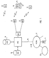
- FIG 1 shows a general view of one cellular radio system according to the invention which is based on the utilization of known radio networks, such as the GSM.
- a WLL network can even be realized as part of a conventional mobile telephone network, in which case there are both WLL subscribers and mobile telephone subscribers in the same network.
- the invention will be explained by using as an example the application of a WLL network in the Pan-European mobile phone network GSM, without restricting the invention, however, thereto.
- the radio system shown in Figure 1 comprises an exchange MSC, a base station controller BSC, a number of base stations BTS and a large number of subscriber terminals SE.
- the exchange MSC comprises a switch for connecting calls, and a call control computer, which controls all signalling between the subscriber terminals and the radio network when a call is established, during the call and when it is ended, and which allocates radio channels for the calls, for the radio connections between a base station BTS and subscriber terminals SE.
- the exchange MSC of the radio system also has a connection 15 to a public switched telephone network PSTN 12 and, through that, to PSTN subscribers 11 or to other networks 22 and their subscribers.
- the base station BTS can also be realized in the same way as a base station of a conventional mobile telephone system, but its basic units are naturally a set of transceivers, the exact number of which is determined by the traffic capacity requirements.
- a WLL subscriber terminal SE typically comprises a mobile telephone unit 13 and a conventional telephone set 14.
- the mobile telephone unit operates as an interface unit to the radio path and provides the user with a normal subscriber line, to which the user can connect his conventional telephone set 14.
- the subscriber terminal can also be a portable mobile telephone, as will be explained below in connection with Figure 2.
- the exchange MSC makes a fixed association between the telephone number of a subscriber terminal and a subscriber terminal SE located in the location area formed by one particular base station BTS or by several base stations.
- the exchange MSC starts paging for the subscriber terminal in the area of the base station BTS indicated by the telephone number or in the location area containing several base stations. Since the location of the subscriber is assumed to be fairly permanent, mobility management functions and location updating are not necessarily needed in the radio system.
- At least one subscriber database in the radio system for example a visitor location register VLR associated with the exchange MSC, the VLR maintaining information about the subscribers in the area of the exchange, or a home location register HLR, where information about the subscribers in the entire network is centralized.
- a visitor location register VLR associated with the exchange MSC the VLR maintaining information about the subscribers in the area of the exchange
- a home location register HLR where information about the subscribers in the entire network is centralized.
- FIG. 2 shows a mobile telephone applicable as a subscriber terminal SE according to the invention.
- the SE comprises an antenna 3, a duplex filter 28, a receiver 21, a transmitter 29 and a synthesizer 27.
- an A/D converter 22, a detector 23, de-interleaving 24, a channel decoder 25, a speech coder 26 and a loudspeaker are connected in series with the receiver 21.
- a modulator 30, TDMA burst formation 31, interleaving 32, a channel coder 33, a speech coder 34 and a microphone are connected in series in front of the transmitter. All the aforementioned blocks are controlled by a timing and control unit 35, which handles all outbound and inbound messages.
- the power source 3 forms the operating voltage V cc for the entire subscriber terminal from an external power source, such as supply voltage provided by the mains, a solar cell or an aggregate, or from the voltage of a battery 10 operating as a backup power source.
- the power source 3 also operates as the charging device for the battery 10 when the external power source is connected.
- the power source 3 continuously measures the charge level of the battery 10, its charging current and/or the state of an external power source 2, and reports the test result to the control unit 35.
- the receiver 21 measures the level of the signal received from the base station through the radio path and reports the test results to the control unit 35.
- the channel decoder 25 measures the signal quality of the control channel of the base station by means of, for example, the number of lost information blocks and reports the test result to the control unit 35.
- the control unit 35 collects and analyzes the test results.
- the control unit 35 can possibly show the test results for the user on the display (not shown in the Figure) of the subscriber terminal, and if some failure or malfunction is detected,
- the subscriber terminal reports the test results to the fixed network in a special message, hereafter called a test report message.
- This message can be transmitted whenever a signalling connection is established between a subscriber terminal and the base station.
- the control unit 35 detects a change in the status of the battery 10, a break in the charging current of the battery and/or a failure in the external power supply during a call, it immediately generates and transmits a test report message. If the status of the battery changes, its charging current breaks and/or if there is a failure in the external power supply or if the measurements on the radio path indicate a malfunction when the subscriber terminal is in an idle state, the control unit 35 generates and transmits a test report message when the next signalling connection is established.
- the subscriber terminal transmits the test results to the fixed network at predetermined intervals.
- the control unit 35 of the subscriber terminal comprises a special timer; expiring of the timer initiates transmission of a new test report message.
- This timer is preferably a periodic location updating timer of a subscriber terminal, in which case a test report is always transmitted during a location updating procedure, when the timer reaches the predetermined time.
- a WLL network where the subscriber terminals are in fixed locations, does not necessarily require the use of any kind of periodic location updating procedure, but the functions of this procedure can be used for the reporting according to the invention.
- the base station BTS receives the test report messages transmitted by the subscriber terminal SE and forwards them to the exchange MSC, which forwards the test results to the subscriber database of the network, for example to a visitor location register VLR.
- the visitor location register VLR maintains information about the charge levels of the batteries of the subscriber terminals, the status of their charging current and/or failures in the external power supply, and about the signal level and signal quality measured by the subscriber terminal. This information can be maintained advantageously by the same mechanism as the location data of a normal mobile telephone subscriber.
- the test results can also be forwarded to the operation and maintenance centre OMC of the radio network.
- the VLR also comprises a timer, preferably a periodic location updating timer, which controls the time that elapses in an idle state between two successive test report messages transmitted by the subscriber terminal. If no test report message is received within a predetermined time after the previous report message, the VLR assumes that there is a failure in the subscriber terminal or it is disconnected.
- a timer preferably a periodic location updating timer
- Figure 3 represents a test report message applicable in the GSM system.
- the information elements of the message, beginning from the first line, are:
Abstract
Description
- The invention relates to a radio system providing a wireless local loop, the system comprising a fixed network including at least one exchange, at least one subscriber database and base stations, and subscriber terminals communicating with the fixed network via a radio path, each subscriber terminal comprising a radio transceiver, a power source with a battery backup unit, means for measuring the signal level and signal quality on the radio path between a base station and the subscriber terminal, and means for measuring the charge level of the battery backup unit of the power source.
- The most expensive and the most time-consuming part in setting up conventional cable-based telecommunication networks is cabling, which connects each subscriber to the local exchange. In many cases it is preferable to replace fixed subscriber cables with a radio connection which can be established easily and quickly to connect the subscribers to the public switched telephone network (PSTN) in areas where no subscriber lines are available and it is too expensive, too slow or otherwise impractical to install them. Thus the subscriber network comprises, in the same way as a normal mobile telephone network, base stations connected to the exchange, the subscriber terminals (mobile telephones) having a radio connection with said base stations. Such a system is called a wireless local loop (WLL). Since a WLL radio system is generally an extension of the normal public switched telephone network, it typically uses the normal numbering of a phone network. Alternatively, it is possible to use the numbering of a mobile telephone network. A call to the phone number of a WLL subscriber generally causes the routing of the call always to one and the same exchange and base station connected to it, the base station paging the subscriber via a radio path. It is possible to connect any conventional telephone set to the WLL radio system, and thus the radio path is invisible to the user and provides, through the base station, a point-to-point connection between the WLL telephone set and the exchange.
- The WLL network operator is usually responsible for the equipment at both ends of the radio path. The base station equipment is connected directly to the network and thus it is relatively easy to monitor. However, the operator should also be able to monitor the subscriber terminal at the other end of the radio path. If the level or quality of the signal received by the subscriber terminal is too low, the quality of the call is poor or calls to the subscriber terminal will be completely prevented. This corresponds to a poor or a disconnected subscriber line in a fixed network. In addition, in WLL applications the operator cannot provide power supply for the subscriber terminal through the subscriber line as in a cabled phone network, but the power supply has to be organized locally in the location of the subscriber terminal. This means that the subscriber terminal has to be provided with a battery backup unit to ensure the connection in all situations, for example during a power failure. Therefore, it should be possible to monitor also the power supply of the subscriber terminal, the charge level of the battery backup unit and preferably also any malfunctions related to the supply of charging current.
- EP-A-0 544 635 discloses a mobile telecommunication network wherein information with respect to network performance is transmitted from the mobile subscriber terminals to the fixed part of the network.
- Mobile telephones for conventional mobile telephone networks conduct, in an idle state, some kind of measurements on the received signal level and quality of the radio channel. A typical mobile telephone also measures the charge level of the battery. These measurements are conducted, however, only for the user of the mobile telephone, who is responsible for the condition of his own mobile telephone in a conventional mobile phone network. The measured information is shown to the user on the display of the mobile telephone, and if some failure is detected, the user is alarmed. US Patent 5,142,563 discloses a similar application, where the portable part of a wireless telephone monitors the voltage level of its battery power source, and when the voltage level drops, sends a signal to the fixed part, the so-called base station, of the wireless telephone, the signal directing the base station to a quick-charging state to wait for the wireless telephone to be positioned on the charging device of the base station. The base station is meant to be connected to a normal subscriber line of a wired telephone network. The operator of a conventional mobile telephone network or a fixed network is not responsible, however, for the working condition of the wireless terminal equipment or the mobile telephone of the subscriber, but, instead, what is provided is only a local indication about the condition of the terminal equipment, given to the user or intended for the internal use of the terminal equipment. Such a local indication is not suitable, however, for the operator of a WLL network, since its utilization would require repeated visits to the mobile telephone or the wireless telephone, and would thus be extremely difficult and would mean long intervals between the checks. The operator of a WLL network needs such information centralized in one place, so that the operator could control the accessibility of the network and the need for maintenance.
- The object of the invention is a radio system providing a wireless local loop and collecting the aforementioned information.
- This object is achieved by means of a radio system similar to the one described in the introductory paragraph, the system being characterized according to the invention in that the subscriber terminal transmits the test results concerning the battery backup unit and/or the state of the power supply to the fixed network in a predetermined report message at predetermined intervals or in response to a predetermined test result, and that said at least one subscriber database of the radio network maintains information about the state of the power supply of the subscriber terminals and/or the charge levels of the batteries, and about the signal level and signal quality measured by the subscriber terminal.
- According to the invention, the subscriber terminal reports the test results concerning the power supply and/or the battery backup unit and the level and quality of the received signal to the network in a special test report message. This message can be transmitted whenever a signalling connection is established, at suitable intervals and in special situations. The test report messages are used for updating the subscriber database of the fixed network, the database containing information about the state of the power supply of the subscriber terminals and/or the charge levels of the battery backup units and about the signal level and quality measured by the subscriber terminal in order to detect malfunctions concerning the battery backup unit. If for example reports about a break in the charging current of the battery backup unit are desired from subscriber terminals, the invention provides a method which prevents overloading of the network as a result of a general power failure, but which ensures transmission of the desired information about an individual break in the charging current before the battery backup unit will be used up.
- The combined processing of information concerning both the battery backup unit and the quality of the connection can provide in some situations essential information in a WLL system. Such a situation may occur for example when power supply is provided by different methods at different times, for example by an aggregate and by solar cells. Equipment malfunctions possibly caused by an individual method are discovered, if the reports giving information about the bad quality of a connection always include a part identifying the specific power supply method.
- The test results can be sent to the fixed network at predetermined intervals under the control of a timer. The timer is preferably a periodic location updating timer, and the test report message is always transmitted during this procedure. In a WLL network, where the subscriber terminals are positioned in fixed locations, it is not necessary to use any kind of periodic location updating procedure; however, it is advantageous to utilize this procedure for the control procedure according to the invention. Thus, it is possible to exploit, with slight modifications, the location updating characteristics provided in the present subscriber terminals and radio networks. The network operator can control the interval between two successive test report messages in an idle state by means of a periodic location updating timer arrangement.
- In addition to periodic reporting, test report messages can be transmitted in response to predetermined test results. If the status of the battery changes during a call, the test report message is transmitted immediately. If the status changes or the radio path measurements indicate faulty conditions in an idle state, the test report message is transmitted when the next signalling connection is established. The subscriber terminal which indicates a failure in the battery can also start the location updating procedure to inform the network about the failure.
- The invention will be described by means of illustrative embodiments with reference to the accompanying drawings, in which
- Figure 1 represents a radio system according to the invention,
- Figure 2 is a block diagram of a subscriber terminal according to the invention.
-
- The present invention can be applied in any radio system which is used as a wireless local loop (WLL) to replace the cabled subscriber lines between a fixed network and the subscribers. Figure 1 shows a general view of one cellular radio system according to the invention which is based on the utilization of known radio networks, such as the GSM. A WLL network can even be realized as part of a conventional mobile telephone network, in which case there are both WLL subscribers and mobile telephone subscribers in the same network. In the following, the invention will be explained by using as an example the application of a WLL network in the Pan-European mobile phone network GSM, without restricting the invention, however, thereto.
- The radio system shown in Figure 1 comprises an exchange MSC, a base station controller BSC, a number of base stations BTS and a large number of subscriber terminals SE. In the same way as a conventional mobile exchange, the exchange MSC comprises a switch for connecting calls, and a call control computer, which controls all signalling between the subscriber terminals and the radio network when a call is established, during the call and when it is ended, and which allocates radio channels for the calls, for the radio connections between a base station BTS and subscriber terminals SE. The exchange MSC of the radio system also has a
connection 15 to a public switchedtelephone network PSTN 12 and, through that, to PSTN subscribers 11 or toother networks 22 and their subscribers. - The base station BTS can also be realized in the same way as a base station of a conventional mobile telephone system, but its basic units are naturally a set of transceivers, the exact number of which is determined by the traffic capacity requirements.
- A WLL subscriber terminal SE typically comprises a
mobile telephone unit 13 and aconventional telephone set 14. The mobile telephone unit operates as an interface unit to the radio path and provides the user with a normal subscriber line, to which the user can connect hisconventional telephone set 14. However, the subscriber terminal can also be a portable mobile telephone, as will be explained below in connection with Figure 2. - In WLL radio systems, the exchange MSC makes a fixed association between the telephone number of a subscriber terminal and a subscriber terminal SE located in the location area formed by one particular base station BTS or by several base stations. When there is a call to the telephone number, the exchange MSC starts paging for the subscriber terminal in the area of the base station BTS indicated by the telephone number or in the location area containing several base stations. Since the location of the subscriber is assumed to be fairly permanent, mobility management functions and location updating are not necessarily needed in the radio system. However, there is at least one subscriber database in the radio system, for example a visitor location register VLR associated with the exchange MSC, the VLR maintaining information about the subscribers in the area of the exchange, or a home location register HLR, where information about the subscribers in the entire network is centralized.
- Figure 2 shows a mobile telephone applicable as a subscriber terminal SE according to the invention. The SE comprises an
antenna 3, aduplex filter 28, areceiver 21, atransmitter 29 and a synthesizer 27. In the receiving direction, an A/D converter 22, adetector 23,de-interleaving 24, achannel decoder 25, aspeech coder 26 and a loudspeaker are connected in series with thereceiver 21. In the transmitting direction, amodulator 30, TDMA burstformation 31, interleaving 32, achannel coder 33, aspeech coder 34 and a microphone are connected in series in front of the transmitter. All the aforementioned blocks are controlled by a timing andcontrol unit 35, which handles all outbound and inbound messages. Thepower source 3 forms the operating voltage Vcc for the entire subscriber terminal from an external power source, such as supply voltage provided by the mains, a solar cell or an aggregate, or from the voltage of abattery 10 operating as a backup power source. Thepower source 3 also operates as the charging device for thebattery 10 when the external power source is connected. Thepower source 3 continuously measures the charge level of thebattery 10, its charging current and/or the state of anexternal power source 2, and reports the test result to thecontrol unit 35. Thereceiver 21 measures the level of the signal received from the base station through the radio path and reports the test results to thecontrol unit 35. Thechannel decoder 25 measures the signal quality of the control channel of the base station by means of, for example, the number of lost information blocks and reports the test result to thecontrol unit 35. Thecontrol unit 35 collects and analyzes the test results. Thecontrol unit 35 can possibly show the test results for the user on the display (not shown in the Figure) of the subscriber terminal, and if some failure or malfunction is detected, it can alarm the user. - According to the invention, the subscriber terminal reports the test results to the fixed network in a special message, hereafter called a test report message. This message can be transmitted whenever a signalling connection is established between a subscriber terminal and the base station. If the
control unit 35 detects a change in the status of thebattery 10, a break in the charging current of the battery and/or a failure in the external power supply during a call, it immediately generates and transmits a test report message. If the status of the battery changes, its charging current breaks and/or if there is a failure in the external power supply or if the measurements on the radio path indicate a malfunction when the subscriber terminal is in an idle state, thecontrol unit 35 generates and transmits a test report message when the next signalling connection is established. Under normal circumstances, the subscriber terminal transmits the test results to the fixed network at predetermined intervals. For this purpose thecontrol unit 35 of the subscriber terminal comprises a special timer; expiring of the timer initiates transmission of a new test report message. This timer is preferably a periodic location updating timer of a subscriber terminal, in which case a test report is always transmitted during a location updating procedure, when the timer reaches the predetermined time. A WLL network, where the subscriber terminals are in fixed locations, does not necessarily require the use of any kind of periodic location updating procedure, but the functions of this procedure can be used for the reporting according to the invention. - The base station BTS receives the test report messages transmitted by the subscriber terminal SE and forwards them to the exchange MSC, which forwards the test results to the subscriber database of the network, for example to a visitor location register VLR. The visitor location register VLR maintains information about the charge levels of the batteries of the subscriber terminals, the status of their charging current and/or failures in the external power supply, and about the signal level and signal quality measured by the subscriber terminal. This information can be maintained advantageously by the same mechanism as the location data of a normal mobile telephone subscriber. Advantageously, the test results can also be forwarded to the operation and maintenance centre OMC of the radio network. The VLR also comprises a timer, preferably a periodic location updating timer, which controls the time that elapses in an idle state between two successive test report messages transmitted by the subscriber terminal. If no test report message is received within a predetermined time after the previous report message, the VLR assumes that there is a failure in the subscriber terminal or it is disconnected.
- Figure 3 represents a test report message applicable in the GSM system. The information elements of the message, beginning from the first line, are:
- line A: transaction identifier and protocol discriminator;
- lines C, D, E: test results of the radio path; in line C the length of the information element (Length), in line D the lowest received power level during a test period (C1 low), in line E the lowest value describing the signal quality (e.g. Downlink signalling radio counter DSC) during a test period (DSC low);
- lines F, G and H contain the test results concerning the battery unit. Line F contains the length of the information element (Length); line G, the status of the battery (Alarm status); line H, the current charge level of the battery (Charge level).
-
- The figures and the description related thereto are only meant to illustrate the present invention. The details of the radio system and subscriber terminal according to the invention can vary within the scope of the appended claims.
Claims (11)
- A radio system providing a wireless local loop, the system comprising a fixed network including at least one exchange (MSC), at least one subscriber database (VLR, HLR) and base stations (BTS), and subscriber terminals (SE) communicating with the fixed network via a radio path, each subscriber terminal comprising a radio transceiver (21, 22), a power source (10) with a battery backup unit, means (21, 25) for measuring the signal level and signal quality on the radio path between a base station and the subscriber terminal, and means (3) for measuring the charge level of the battery backup unit of the power source, characterized in that the subscriber terminal (SE) is adapted to transmit the test results concerning the battery backup unit and/or the state of the power supply to the fixed network in a predetermined report message at predetermined intervals or in response to a predetermined test result, and that said at least one subscriber database (VLR, HLR) of the radio network is adapted to maintain information about the charge levels of the batteries and/or the state of the power supply of the subscriber terminals, and about the signal level and signal quality measured by the subscriber terminal.
- A radio system according to claim 1, characterized in that the subscriber terminal comprises a timer device (35) which initiates transmission of test results to the fixed network at predetermined intervals.
- A radio system according to claim 1 or 2, characterized in that the fixed network comprises a timer device (VLR), which measures the interval between successive transmissions of report messages from the subscriber terminal.
- A radio system according to claim 2 or 3, characterized in that the timer device is a periodic location updating timer, and that the report message is transmitted during the location updating procedure.
- A radio system according to claim 1, 2, 3, or 4, characterized in that the subscriber terminal comprises means (35) for assessing the test results and for transmitting the test result to the fixed network immediately after the next signalling connection has been established, if the test result shows an essential change in the charge level of the battery power source, a break in its charging current and/or a failure in the power supply, or a change in the condition of the radio path.
- A radio system according to any one of the preceding claims, characterized in that the report message contains the lowest signal level measured during the test period, the lowest signal quality measured during the test period and the current charge level of the battery power source.
- A subscriber terminal for a radio system providing a wireless local loop, the system comprising a fixed network including at least one exchange (MSC), at least one subscriber database (VLR, HLR) and base stations (BTS), said subscriber terminal communicating via a radio path with the fixed network and comprising a radio transceiver (21, 22), a battery power source (10), means (21, 25) for measuring the signal level and signal quality on the radio path between a base station and the subscriber terminal, and means (3) for measuring the charge level of the power source with the battery backup unit, characterized in that the subscriber terminal is adapted to transmit the test results concerning the battery backup unit and/or the power supply to the fixed network in a predetermined report message at predetermined intervals, or in response to a predetermined test result.
- A subscriber terminal according to claim 7, characterized in that the subscriber terminal comprises a timer device (35), which initiates transmission of test results to the fixed network at predetermined intervals.
- A subscriber terminal according to claim 8, characterized in that the timer device is a periodic location updating timer, and that the report message is transmitted during the location updating procedure.
- A subscriber terminal according claim 7, 8 or 9, characterized in that the subscriber terminal comprises means (35) for assessing the test results and for transmitting the test result to the fixed network immediately if the test result shows an essential change in the charge level of the battery power source or in the condition of the radio path.
- A subscriber terminal according to any one of the claims 7, 8, 9 or 10, characterized in that the report message contains the lowest signal level measured during the test period, the lowest signal quality measured during the test period, and the current charge level of the battery power source.
Applications Claiming Priority (3)
| Application Number | Priority Date | Filing Date | Title |
|---|---|---|---|
| FI934232 | 1993-09-27 | ||
| FI934232A FI106505B (en) | 1993-09-27 | 1993-09-27 | A radio system implementing a wireless subscriber line and a subscriber unit for a radio system |
| PCT/FI1994/000436 WO1995009512A1 (en) | 1993-09-27 | 1994-09-27 | Radio system and a subscriber terminal for a radio system |
Publications (2)
| Publication Number | Publication Date |
|---|---|
| EP0671111A1 EP0671111A1 (en) | 1995-09-13 |
| EP0671111B1 true EP0671111B1 (en) | 1999-05-12 |
Family
ID=8538670
Family Applications (1)
| Application Number | Title | Priority Date | Filing Date |
|---|---|---|---|
| EP94927683A Expired - Lifetime EP0671111B1 (en) | 1993-09-27 | 1994-09-27 | Radio system and a subscriber terminal for a radio system |
Country Status (10)
| Country | Link |
|---|---|
| US (1) | US5603095A (en) |
| EP (1) | EP0671111B1 (en) |
| JP (1) | JP2983061B2 (en) |
| CN (1) | CN1066003C (en) |
| AT (1) | ATE180135T1 (en) |
| AU (1) | AU676611B2 (en) |
| DE (1) | DE69418449T2 (en) |
| FI (1) | FI106505B (en) |
| NO (1) | NO952089L (en) |
| WO (1) | WO1995009512A1 (en) |
Families Citing this family (81)
| Publication number | Priority date | Publication date | Assignee | Title |
|---|---|---|---|---|
| FI100076B (en) * | 1995-01-04 | 1997-09-15 | Nokia Telecommunications Oy | Radio system for wireless subscriber connection |
| FI100077B (en) * | 1995-01-04 | 1997-09-15 | Nokia Telecommunications Oy | Radio system for wireless subscriber connection |
| GB2301743B (en) * | 1995-06-02 | 2000-01-26 | Dsc Communications | Subscriber terminal for a wireless telecommunications system |
| WO1997001942A1 (en) * | 1995-06-28 | 1997-01-16 | Mci Communications Corporation | Method and apparatus for improved call connectivity in an intelligent wireless network |
| US5982854A (en) | 1996-02-23 | 1999-11-09 | Alcatel Usa, Inc. | Fiber optic based subscriber terminal |
| FI103167B (en) * | 1996-03-07 | 1999-04-30 | Nokia Telecommunications Oy | A method for determining the condition of a subscriber unit |
| FI102124B1 (en) * | 1996-03-07 | 1998-10-15 | Nokia Telecommunications Oy | Remote testing of a local loop in a radio system implemented by a wireless local loop |
| KR100310100B1 (en) * | 1996-07-10 | 2001-12-17 | 윤종용 | Power supply apparatus for portable computer and dc input selection circuit adapted to same |
| SE517413C2 (en) * | 1996-07-25 | 2002-06-04 | Telia Ab | Improvements in, or relating to, the measurement of the quality of telecommunications connections |
| US5859838A (en) * | 1996-07-30 | 1999-01-12 | Qualcomm Incorporated | Load monitoring and management in a CDMA wireless communication system |
| US6370149B1 (en) * | 1998-07-20 | 2002-04-09 | Ameritech Corporation | Telecommunication system, method and subscriber unit for use therein |
| US7187686B1 (en) * | 1996-11-01 | 2007-03-06 | Sbc Properties, B.P. | Telecommunication system, method and subscriber unit for use therein |
| US5960327A (en) * | 1996-12-06 | 1999-09-28 | Motorola | Method for a transceiver to select a channel |
| CA2274660C (en) * | 1996-12-11 | 2005-12-06 | Telefonaktiebolaget Lm Ericsson | Mobile communication apparatus uplink message transmission of battery output level information |
| US5933421A (en) | 1997-02-06 | 1999-08-03 | At&T Wireless Services Inc. | Method for frequency division duplex communications |
| US6085114A (en) | 1997-02-06 | 2000-07-04 | At&T Wireless Systems Inc. | Remote wireless unit having reduced power operating mode |
| US6501771B2 (en) | 1997-02-11 | 2002-12-31 | At&T Wireless Services, Inc. | Delay compensation |
| WO1998037653A2 (en) * | 1997-02-19 | 1998-08-27 | At & T Wireless Services, Inc. | Remote wireless unit having reduced power operating mode for a discrete multitone spread spectrum communications system |
| US6584144B2 (en) | 1997-02-24 | 2003-06-24 | At&T Wireless Services, Inc. | Vertical adaptive antenna array for a discrete multitone spread spectrum communications system |
| US6826394B1 (en) * | 1997-04-22 | 2004-11-30 | Ericsson Inc. | Interaction between an adjunct positioning system and a radiocommunication system |
| US6347217B1 (en) * | 1997-05-22 | 2002-02-12 | Telefonaktiebolaget Lm Ericsson (Publ) | Link quality reporting using frame erasure rates |
| JP3158077B2 (en) * | 1997-05-23 | 2001-04-23 | 松下電器産業株式会社 | Wireless local loop system |
| JP3260657B2 (en) * | 1997-05-23 | 2002-02-25 | 松下電器産業株式会社 | Wireless fixed terminal |
| US5949763A (en) | 1997-07-17 | 1999-09-07 | Ameritech Corporation | Method and apparatus for providing broadband access conferencing services |
| US6104909A (en) * | 1997-07-30 | 2000-08-15 | Motorola, Inc. | Method and apparatus for reporting status information in a fixed wireless terminal |
| GB2328842B (en) * | 1997-08-29 | 2002-06-19 | Nokia Mobile Phones Ltd | Monitoring signal quality in a wireless local loop communication system |
| SE512115C2 (en) * | 1997-09-08 | 2000-01-24 | Ericsson Telefon Ab L M | Test transmitter and method of manufacturing a mobile test transmitter for a mobile telecommunication system |
| US5974327A (en) * | 1997-10-21 | 1999-10-26 | At&T Corp. | Adaptive frequency channel assignment based on battery power level in wireless access protocols |
| US6141356A (en) | 1997-11-10 | 2000-10-31 | Ameritech Corporation | System and method for distributing voice and data information over wireless and wireline networks |
| ATE358951T1 (en) * | 1997-12-10 | 2007-04-15 | Xircom Wireless Inc | COMMUNICATION SYSTEM AND METHOD FOR ADDRESSING MULTI-CAPACITY WIRELESS CONNECTION LINES |
| AU1823799A (en) | 1997-12-29 | 1999-07-19 | Ameritech Corporation | System and method for home automation and security |
| US7349682B1 (en) * | 1998-06-12 | 2008-03-25 | Sbc Properties, L.P. | Home gateway system for automation and security |
| US9294629B2 (en) | 1998-04-16 | 2016-03-22 | At&T Intellectual Property I, L.P. | Home gateway system with telephony functions and method |
| US6115370A (en) | 1998-05-26 | 2000-09-05 | Nera Wireless Broadband Access As | Method and system for protocols for providing voice, data, and multimedia services in a wireless local loop system |
| US6131012A (en) | 1998-05-26 | 2000-10-10 | Nera Wireless Broadband Access As | Method and system for a micro-channel bank for providing voice, data, and multimedia services in a wireless local loop system |
| US6144645A (en) * | 1998-05-26 | 2000-11-07 | Nera Wireless Broadband Access As | Method and system for an air interface for providing voice, data, and multimedia services in a wireless local loop system |
| US6188912B1 (en) | 1998-06-05 | 2001-02-13 | World Access, Inc. | System for a base station for providing voice, data, and multimedia services in a wireless local loop system |
| GB2339646A (en) | 1998-07-15 | 2000-02-02 | Ericsson Telefon Ab L M | Reduction of Interference between Radio Links |
| GB9820271D0 (en) * | 1998-09-17 | 1998-11-11 | Simoco Int Ltd | A method of and apparatus for monitoring the condition of batteries used by a mobile radio telecommunications fleet |
| US6389283B1 (en) * | 1998-10-15 | 2002-05-14 | Telefonaktiebolaget Lm Ericsson (Publ) | Release of remaining activities in VPLMNs |
| US6480727B1 (en) * | 1999-01-12 | 2002-11-12 | Tellabs Operations, Inc. | Using inactivity levels to extend subscriber equipment battery life |
| JP4120903B2 (en) * | 1999-03-19 | 2008-07-16 | 富士通株式会社 | Wireless local loop system and radio link control method |
| US6285671B1 (en) | 1999-04-22 | 2001-09-04 | Ameritech Corporation | Method and system for providing facsimile service over a digital subscriber line |
| US6335936B1 (en) * | 1999-04-22 | 2002-01-01 | Ameritech Corporation | Wide area communication networking |
| US6434129B1 (en) | 1999-12-01 | 2002-08-13 | Nera Wireless Broadband Access As | Method and system for an air interface for providing voice, data, and multimedia services in a wireless local loop system |
| US7346347B2 (en) | 2001-01-19 | 2008-03-18 | Raze Technologies, Inc. | Apparatus, and an associated method, for providing WLAN service in a fixed wireless access communication system |
| US20090111457A1 (en) | 2007-10-31 | 2009-04-30 | Raze Technologies, Inc. | Wireless communication system and device for coupling a base station and mobile stations |
| IT1321104B1 (en) * | 2000-12-15 | 2003-12-30 | Cselt Centro Studi Lab Telecom | METHOD FOR REPORTING AN IMMINENT DEACTIVATION OF A MOBILE EQUIPMENT IN A TELECOMMUNICATIONS AND SYSTEM AND EQUIPMENT NETWORK |
| JP3528799B2 (en) * | 2001-01-24 | 2004-05-24 | 日本電気株式会社 | Terminal device, terminal monitoring system, and terminal monitoring method |
| JP2002281128A (en) | 2001-03-16 | 2002-09-27 | Nec Corp | Portable telephone terminal, its battery capacity notifying method and its program |
| KR100556241B1 (en) * | 2002-01-25 | 2006-03-03 | 삼성전자주식회사 | Portable computer and method of controlling the same |
| KR100987651B1 (en) * | 2002-06-27 | 2010-10-13 | 코닌클리즈케 필립스 일렉트로닉스 엔.브이. | Measurement of channel characteristics in a communication system |
| KR20050026093A (en) * | 2002-08-01 | 2005-03-14 | 인터디지탈 테크날러지 코포레이션 | Power control of point to multipoint physical channels |
| US7117007B2 (en) | 2002-09-10 | 2006-10-03 | Axesstel, Inc. | Enhanced mobility wireless local loop phone |
| US7010329B2 (en) * | 2003-03-11 | 2006-03-07 | Interdigital Technology Corp. | System and method for battery conservation with assistance from the network and radio resource management |
| AU2004237951A1 (en) * | 2003-05-16 | 2004-11-25 | Pfizer Products Inc. | Therapeutic combinations of atypical antipsychotics with GABA modulators, anticonvulsants or benzodiazapines |
| US7529544B1 (en) * | 2004-02-23 | 2009-05-05 | Sprint Spectrum L.P. | Method and system for initiating a communication with a network entity to communicate information regarding a fixed wireless device |
| KR100594080B1 (en) * | 2004-03-08 | 2006-06-30 | 삼성전자주식회사 | System and mothod for controlling displaying origination number |
| EP1596616A1 (en) * | 2004-05-14 | 2005-11-16 | Research In Motion Limited | Method and apparatus for expeditiously releasing network resources for a mobile station based on low battery and lost signal conditions |
| US7130667B2 (en) * | 2004-05-14 | 2006-10-31 | Research In Motion Limited | Methods and apparatus for expeditiously releasing network resources for a mobile station based on low battery and lost signal conditions |
| JP4421946B2 (en) * | 2004-05-31 | 2010-02-24 | 京セラ株式会社 | Communication terminal device and communication method thereof |
| CN100384294C (en) * | 2004-09-30 | 2008-04-23 | 华为技术有限公司 | Method for realizing roaming limitation |
| US7561877B2 (en) * | 2005-03-18 | 2009-07-14 | Qualcomm Incorporated | Apparatus and methods for managing malfunctions on a wireless device |
| CA2666199C (en) | 2006-03-27 | 2015-08-25 | Nielsen Media Research, Inc. | Methods and systems to meter media content presented on a wireless communication device |
| US8260252B2 (en) * | 2006-10-02 | 2012-09-04 | The Nielsen Company (Us), Llc | Method and apparatus for collecting information about portable device usage |
| US8014726B1 (en) | 2006-10-02 | 2011-09-06 | The Nielsen Company (U.S.), Llc | Method and system for collecting wireless information transparently and non-intrusively |
| US20080221968A1 (en) * | 2007-03-07 | 2008-09-11 | Tamara Gaffney | Method and system for interacting with users of portable devices |
| US8321556B1 (en) | 2007-07-09 | 2012-11-27 | The Nielsen Company (Us), Llc | Method and system for collecting data on a wireless device |
| US20090150217A1 (en) | 2007-11-02 | 2009-06-11 | Luff Robert A | Methods and apparatus to perform consumer surveys |
| US8532001B2 (en) * | 2008-03-11 | 2013-09-10 | Intel Corporation | Beaconing and frame structure for directional antenna communications |
| US8503991B2 (en) * | 2008-04-03 | 2013-08-06 | The Nielsen Company (Us), Llc | Methods and apparatus to monitor mobile devices |
| CA2761391A1 (en) | 2009-05-08 | 2010-11-11 | Zokem Oy | System and method for behavioural and contextual data analytics |
| US8543659B2 (en) | 2010-03-02 | 2013-09-24 | Qualcomm Incorporated | Apparatus and method for user equipment battery information reporting |
| KR101650993B1 (en) | 2010-06-24 | 2016-08-24 | 더 닐슨 컴퍼니 (유에스) 엘엘씨 | Network server arrangement for processing non-parametric, multi-dimensional, spatial and temporal human behavior or technical observations measured pervasively, and related method for the same |
| US8340685B2 (en) | 2010-08-25 | 2012-12-25 | The Nielsen Company (Us), Llc | Methods, systems and apparatus to generate market segmentation data with anonymous location data |
| EP2753112A4 (en) * | 2011-10-28 | 2014-11-26 | Huawei Tech Co Ltd | User equipment processing method, mobility management entity processing method, user equipment, and mobility management entity and communication system |
| WO2013099229A2 (en) | 2011-12-30 | 2013-07-04 | Makita Corporation | Battery system for a power tool, as well as battery holder therefor, charger, and charging system |
| US9173185B1 (en) | 2012-04-10 | 2015-10-27 | Sprint Spectrum L.P. | Methods and systems for managing registration signaling based on off-time duration |
| US9781496B2 (en) | 2012-10-25 | 2017-10-03 | Milwaukee Electric Tool Corporation | Worksite audio device with wireless interface |
| USD741795S1 (en) | 2013-10-25 | 2015-10-27 | Milwaukee Electric Tool Corporation | Radio charger |
| US10083459B2 (en) | 2014-02-11 | 2018-09-25 | The Nielsen Company (Us), Llc | Methods and apparatus to generate a media rank |
Family Cites Families (5)
| Publication number | Priority date | Publication date | Assignee | Title |
|---|---|---|---|---|
| US4367458A (en) * | 1980-08-29 | 1983-01-04 | Ultrak Inc. | Supervised wireless security system |
| JPH07121023B2 (en) * | 1989-11-13 | 1995-12-20 | 松下電器産業株式会社 | Cordless phone |
| JPH0815267B2 (en) * | 1991-09-27 | 1996-02-14 | 松下電器産業株式会社 | Wireless phone |
| US5291411A (en) * | 1991-11-12 | 1994-03-01 | Bianco James S | Apparatus and method for reviewing path of travel |
| SE469460B (en) * | 1991-11-27 | 1993-07-05 | Televerket | PROCEDURE AND DEVICE FOR TERMINAL-ORIENTED QUALITY MONITORING IN THE TELECOMMUNICATIONS |
-
1993
- 1993-09-27 FI FI934232A patent/FI106505B/en active
-
1994
- 1994-09-27 AT AT94927683T patent/ATE180135T1/en not_active IP Right Cessation
- 1994-09-27 EP EP94927683A patent/EP0671111B1/en not_active Expired - Lifetime
- 1994-09-27 CN CN94190722A patent/CN1066003C/en not_active Expired - Fee Related
- 1994-09-27 JP JP7510130A patent/JP2983061B2/en not_active Expired - Lifetime
- 1994-09-27 AU AU77006/94A patent/AU676611B2/en not_active Ceased
- 1994-09-27 US US08/436,468 patent/US5603095A/en not_active Expired - Lifetime
- 1994-09-27 DE DE69418449T patent/DE69418449T2/en not_active Expired - Fee Related
- 1994-09-27 WO PCT/FI1994/000436 patent/WO1995009512A1/en active IP Right Grant
-
1995
- 1995-05-26 NO NO952089A patent/NO952089L/en not_active Application Discontinuation
Also Published As
| Publication number | Publication date |
|---|---|
| FI934232A0 (en) | 1993-09-27 |
| AU676611B2 (en) | 1997-03-13 |
| WO1995009512A1 (en) | 1995-04-06 |
| DE69418449D1 (en) | 1999-06-17 |
| EP0671111A1 (en) | 1995-09-13 |
| JPH08504071A (en) | 1996-04-30 |
| NO952089D0 (en) | 1995-05-26 |
| CN1114851A (en) | 1996-01-10 |
| FI106505B (en) | 2001-02-15 |
| AU7700694A (en) | 1995-04-18 |
| CN1066003C (en) | 2001-05-16 |
| DE69418449T2 (en) | 1999-10-28 |
| JP2983061B2 (en) | 1999-11-29 |
| FI934232A (en) | 1995-03-28 |
| ATE180135T1 (en) | 1999-05-15 |
| US5603095A (en) | 1997-02-11 |
| NO952089L (en) | 1995-07-26 |
Similar Documents
| Publication | Publication Date | Title |
|---|---|---|
| EP0671111B1 (en) | Radio system and a subscriber terminal for a radio system | |
| JP3019061B2 (en) | Mobile communication system and radio channel control method therefor | |
| WO1999023848A2 (en) | Network element monitoring in a radio telecommunication network | |
| RU2006103261A (en) | SYSTEM AND METHOD FOR INSTALLING A QUICK CALL IN A MOBILE COMMUNICATION SYSTEM | |
| WO2002041511A1 (en) | Operations, administration and maintenance of components in a mobility network | |
| KR100369796B1 (en) | Method for alarming cell secession in mobile station of mobile telecommunication system | |
| US7328008B2 (en) | Means and method for measuring the status of a core interface between two core subnetworks in a telecommunication system | |
| US5475736A (en) | Radio communication system which displays status of wired lines | |
| JP2979199B2 (en) | Communication traffic adaptive wireless zone configuration method | |
| JP2000506337A (en) | Method and system for testing the status of a subscriber station in a wireless system | |
| US6697618B1 (en) | System and method for detecting failures in a wireless phone/modem jack to prevent telephone line seizures | |
| JPH06276164A (en) | Inter-base station mutual monitoring system | |
| KR100307305B1 (en) | Monitoring system of the repeater and method thereof | |
| JP3797842B2 (en) | Wireless device failure diagnosis method | |
| JP2609660B2 (en) | Failure detection method | |
| JP3003286B2 (en) | Mobile radio system with control channel switching function | |
| JP2646964B2 (en) | Mobile switching system | |
| JP4314379B2 (en) | Traffic concentration reduction method using pager | |
| JPH04260232A (en) | Control channel monitor system for mobile communication system | |
| JP2605619B2 (en) | Notification method of maintenance operation information | |
| JP2023074169A (en) | Communication monitoring device, communication monitoring system, communication monitoring method, and program | |
| EP0930591A1 (en) | Automatically locating individuals utilizing a combination of wireless media | |
| JP2927260B2 (en) | Status monitoring method | |
| JPH06224831A (en) | Mobile radio communication system | |
| JPH04371033A (en) | Mobile radio telephone system |
Legal Events
| Date | Code | Title | Description |
|---|---|---|---|
| PUAI | Public reference made under article 153(3) epc to a published international application that has entered the european phase |
Free format text: ORIGINAL CODE: 0009012 |
|
| AK | Designated contracting states |
Kind code of ref document: A1 Designated state(s): AT BE CH DE DK ES FR GB GR IE IT LI LU MC NL PT SE |
|
| 17P | Request for examination filed |
Effective date: 19950928 |
|
| RAP1 | Party data changed (applicant data changed or rights of an application transferred) |
Owner name: NOKIA TELECOMMUNICATIONS OY |
|
| GRAG | Despatch of communication of intention to grant |
Free format text: ORIGINAL CODE: EPIDOS AGRA |
|
| 17Q | First examination report despatched |
Effective date: 19980724 |
|
| GRAG | Despatch of communication of intention to grant |
Free format text: ORIGINAL CODE: EPIDOS AGRA |
|
| GRAH | Despatch of communication of intention to grant a patent |
Free format text: ORIGINAL CODE: EPIDOS IGRA |
|
| GRAH | Despatch of communication of intention to grant a patent |
Free format text: ORIGINAL CODE: EPIDOS IGRA |
|
| GRAA | (expected) grant |
Free format text: ORIGINAL CODE: 0009210 |
|
| AK | Designated contracting states |
Kind code of ref document: B1 Designated state(s): AT BE CH DE DK ES FR GB GR IE IT LI LU MC NL PT SE |
|
| PG25 | Lapsed in a contracting state [announced via postgrant information from national office to epo] |
Ref country code: GR Free format text: LAPSE BECAUSE OF NON-PAYMENT OF DUE FEES Effective date: 19990512 |
|
| REF | Corresponds to: |
Ref document number: 180135 Country of ref document: AT Date of ref document: 19990515 Kind code of ref document: T |
|
| REG | Reference to a national code |
Ref country code: CH Ref legal event code: NV Representative=s name: ICB INGENIEURS CONSEILS EN BREVETS SA Ref country code: CH Ref legal event code: EP |
|
| REG | Reference to a national code |
Ref country code: IE Ref legal event code: FG4D |
|
| REF | Corresponds to: |
Ref document number: 69418449 Country of ref document: DE Date of ref document: 19990617 |
|
| ET | Fr: translation filed | ||
| PG25 | Lapsed in a contracting state [announced via postgrant information from national office to epo] |
Ref country code: PT Free format text: LAPSE BECAUSE OF FAILURE TO SUBMIT A TRANSLATION OF THE DESCRIPTION OR TO PAY THE FEE WITHIN THE PRESCRIBED TIME-LIMIT Effective date: 19990812 Ref country code: DK Free format text: LAPSE BECAUSE OF FAILURE TO SUBMIT A TRANSLATION OF THE DESCRIPTION OR TO PAY THE FEE WITHIN THE PRESCRIBED TIME-LIMIT Effective date: 19990812 |
|
| PGFP | Annual fee paid to national office [announced via postgrant information from national office to epo] |
Ref country code: ES Payment date: 19990920 Year of fee payment: 6 |
|
| PGFP | Annual fee paid to national office [announced via postgrant information from national office to epo] |
Ref country code: IE Payment date: 19990927 Year of fee payment: 6 |
|
| PG25 | Lapsed in a contracting state [announced via postgrant information from national office to epo] |
Ref country code: ES Free format text: LAPSE BECAUSE OF FAILURE TO SUBMIT A TRANSLATION OF THE DESCRIPTION OR TO PAY THE FEE WITHIN THE PRESCRIBED TIME-LIMIT Effective date: 19991118 |
|
| RAP2 | Party data changed (patent owner data changed or rights of a patent transferred) |
Owner name: NOKIA NETWORKS OY |
|
| NLT2 | Nl: modifications (of names), taken from the european patent patent bulletin |
Owner name: NOKIA NETWORKS OY |
|
| PLBE | No opposition filed within time limit |
Free format text: ORIGINAL CODE: 0009261 |
|
| STAA | Information on the status of an ep patent application or granted ep patent |
Free format text: STATUS: NO OPPOSITION FILED WITHIN TIME LIMIT |
|
| 26N | No opposition filed | ||
| PGFP | Annual fee paid to national office [announced via postgrant information from national office to epo] |
Ref country code: LU Payment date: 20000925 Year of fee payment: 7 |
|
| PG25 | Lapsed in a contracting state [announced via postgrant information from national office to epo] |
Ref country code: IE Free format text: LAPSE BECAUSE OF NON-PAYMENT OF DUE FEES Effective date: 20000927 |
|
| PGFP | Annual fee paid to national office [announced via postgrant information from national office to epo] |
Ref country code: MC Payment date: 20001002 Year of fee payment: 7 |
|
| REG | Reference to a national code |
Ref country code: IE Ref legal event code: MM4A |
|
| PGFP | Annual fee paid to national office [announced via postgrant information from national office to epo] |
Ref country code: SE Payment date: 20010906 Year of fee payment: 8 |
|
| PGFP | Annual fee paid to national office [announced via postgrant information from national office to epo] |
Ref country code: FR Payment date: 20010911 Year of fee payment: 8 |
|
| PGFP | Annual fee paid to national office [announced via postgrant information from national office to epo] |
Ref country code: AT Payment date: 20010912 Year of fee payment: 8 |
|
| PG25 | Lapsed in a contracting state [announced via postgrant information from national office to epo] |
Ref country code: MC Free format text: LAPSE BECAUSE OF NON-PAYMENT OF DUE FEES Effective date: 20010927 Ref country code: LU Free format text: LAPSE BECAUSE OF NON-PAYMENT OF DUE FEES Effective date: 20010927 |
|
| PGFP | Annual fee paid to national office [announced via postgrant information from national office to epo] |
Ref country code: NL Payment date: 20010927 Year of fee payment: 8 |
|
| PGFP | Annual fee paid to national office [announced via postgrant information from national office to epo] |
Ref country code: CH Payment date: 20011015 Year of fee payment: 8 |
|
| PGFP | Annual fee paid to national office [announced via postgrant information from national office to epo] |
Ref country code: BE Payment date: 20011116 Year of fee payment: 8 |
|
| REG | Reference to a national code |
Ref country code: GB Ref legal event code: IF02 |
|
| REG | Reference to a national code |
Ref country code: GB Ref legal event code: 732E |
|
| PG25 | Lapsed in a contracting state [announced via postgrant information from national office to epo] |
Ref country code: AT Free format text: LAPSE BECAUSE OF NON-PAYMENT OF DUE FEES Effective date: 20020927 |
|
| PG25 | Lapsed in a contracting state [announced via postgrant information from national office to epo] |
Ref country code: SE Free format text: LAPSE BECAUSE OF NON-PAYMENT OF DUE FEES Effective date: 20020928 |
|
| PG25 | Lapsed in a contracting state [announced via postgrant information from national office to epo] |
Ref country code: LI Free format text: LAPSE BECAUSE OF NON-PAYMENT OF DUE FEES Effective date: 20020930 Ref country code: CH Free format text: LAPSE BECAUSE OF NON-PAYMENT OF DUE FEES Effective date: 20020930 Ref country code: BE Free format text: LAPSE BECAUSE OF NON-PAYMENT OF DUE FEES Effective date: 20020930 |
|
| BERE | Be: lapsed |
Owner name: *NOKIA TELECOMMUNICATIONS OY Effective date: 20020930 |
|
| PG25 | Lapsed in a contracting state [announced via postgrant information from national office to epo] |
Ref country code: NL Free format text: LAPSE BECAUSE OF NON-PAYMENT OF DUE FEES Effective date: 20030401 |
|
| EUG | Se: european patent has lapsed | ||
| REG | Reference to a national code |
Ref country code: CH Ref legal event code: PL |
|
| PG25 | Lapsed in a contracting state [announced via postgrant information from national office to epo] |
Ref country code: FR Free format text: LAPSE BECAUSE OF NON-PAYMENT OF DUE FEES Effective date: 20030603 |
|
| REG | Reference to a national code |
Ref country code: FR Ref legal event code: ST |
|
| PGFP | Annual fee paid to national office [announced via postgrant information from national office to epo] |
Ref country code: GB Payment date: 20040922 Year of fee payment: 11 |
|
| PG25 | Lapsed in a contracting state [announced via postgrant information from national office to epo] |
Ref country code: IT Free format text: LAPSE BECAUSE OF NON-PAYMENT OF DUE FEES;WARNING: LAPSES OF ITALIAN PATENTS WITH EFFECTIVE DATE BEFORE 2007 MAY HAVE OCCURRED AT ANY TIME BEFORE 2007. THE CORRECT EFFECTIVE DATE MAY BE DIFFERENT FROM THE ONE RECORDED. Effective date: 20050927 Ref country code: GB Free format text: LAPSE BECAUSE OF NON-PAYMENT OF DUE FEES Effective date: 20050927 |
|
| GBPC | Gb: european patent ceased through non-payment of renewal fee |
Effective date: 20050927 |
|
| PGFP | Annual fee paid to national office [announced via postgrant information from national office to epo] |
Ref country code: DE Payment date: 20060922 Year of fee payment: 13 |
|
| PG25 | Lapsed in a contracting state [announced via postgrant information from national office to epo] |
Ref country code: DE Free format text: LAPSE BECAUSE OF NON-PAYMENT OF DUE FEES Effective date: 20080401 |