EP0670541A2 - System and method for computer cursor control - Google Patents
System and method for computer cursor control Download PDFInfo
- Publication number
- EP0670541A2 EP0670541A2 EP95103086A EP95103086A EP0670541A2 EP 0670541 A2 EP0670541 A2 EP 0670541A2 EP 95103086 A EP95103086 A EP 95103086A EP 95103086 A EP95103086 A EP 95103086A EP 0670541 A2 EP0670541 A2 EP 0670541A2
- Authority
- EP
- European Patent Office
- Prior art keywords
- cursor
- border
- indicator signal
- display
- movement
- Prior art date
- Legal status (The legal status is an assumption and is not a legal conclusion. Google has not performed a legal analysis and makes no representation as to the accuracy of the status listed.)
- Withdrawn
Links
Images

Classifications
-
- G—PHYSICS
- G06—COMPUTING; CALCULATING OR COUNTING
- G06F—ELECTRIC DIGITAL DATA PROCESSING
- G06F3/00—Input arrangements for transferring data to be processed into a form capable of being handled by the computer; Output arrangements for transferring data from processing unit to output unit, e.g. interface arrangements
- G06F3/01—Input arrangements or combined input and output arrangements for interaction between user and computer
- G06F3/048—Interaction techniques based on graphical user interfaces [GUI]
- G06F3/0481—Interaction techniques based on graphical user interfaces [GUI] based on specific properties of the displayed interaction object or a metaphor-based environment, e.g. interaction with desktop elements like windows or icons, or assisted by a cursor's changing behaviour or appearance
- G06F3/04812—Interaction techniques based on cursor appearance or behaviour, e.g. being affected by the presence of displayed objects
Definitions
- the invention relates generally to a system and method for control of a cursor on a computer display screen.
- Computers have become common in the work place and at home. Early computer systems required extensive knowledge of computer programming to effectively operate the computer. Newer computers have been designed to permit simplified use by those without formal background in computer science. Operating systems, such as the Microsoft® WindowsTM operating system provide a graphical environment that can be used by persons with little or no previous experience in the use of computers. Thus, computers have become easier to operate and their use has become more pervasive.
- a cursor pointing device such as a mouse, trackball, or the like
- a cursor pointing device permits the easy manipulation of a cursor on the visual display coupled to the computer.
- a cursor pointing device such as a mouse, trackball, or the like
- the movement of the cursor with a mouse becomes inefficient.
- the movement of the cursor from one side of the visual display to the opposite side of the visual display requires extensive manipulation of the mouse.
- some prior art systems permit the movement of the cursor off one side of the visual display and cause the cursor to reappear on the opposite side of the visual display. This technique, known as screen wrapping, can simplify the movement of the cursor.
- the present invention is embodied in a system and method for controlling cursor movement using a display having first and second opposing borders, and means for restricting the movement of the cursor beyond the first border.
- Signal generation means generate an indicator signal in response to a user effort to move the cursor beyond the first barrier.
- Wrapping means enabled by the indicator signal, wrap the cursor from a location in the vicinity of the first border on the display to a location in the vicinity of the second border.
- the first and second borders may be visually detectable to the user.
- the indicator signal may be generated by a variety of means such as continued movement of the cursor against the first border.
- the indicator signal may be generated when the cursor is moved against the first border for a predetermined period of time or for a predetermined distance.
- the indicator signal may be generated in response to the detection of a rate of movement with which the cursor approaches the first border.
- the rate of movement may be a velocity.
- the indicator signal may be generated when the velocity is below a predetermined velocity.
- the detected rate of movement may be an acceleration.
- the indicator signal may be generated when the acceleration is below a predetermined acceleration.
- the system may further include a command entry device operable by the user, with the indicator signal beam generated by the user activating the command entry device.
- the system has selectively enabled wrapping means for wrapping the cursor from a location in the vicinity of the first border to a location in the vicinity of the second border.
- the wrapping means having enabled mode for restricting movement of the cursor beyond the first border in a disabled mode for permitting the movement of the cursor beyond the first border.
- the signal generation means generate an indicator signal in response to a user effort to move the cursor beyond the first border with the indicator signal placing the wrapping means in the disabled mode.
- the signal generation means may initially place the wrapping means in a disabled mode with the first crossing of the first border causing the signal generation means to place the wrapping means in the enabled mode.
- the signal generation means may subsequently return the wrapping means to the disabled mode by the generation of the indicator signal.
- the indicator signal is generated by the continued movement of the cursor against the first border for a first predetermined period of time.
- the system may also include adjustment means for increasing the first predetermined period of time following the generation of the indicator signal for a first time such that the indicator signal is generated a second time by continued movement of the cursor against one of the first or second borders for an increased period of time.
- the adjustment means may increase the first predetermined period of time each time that the cursor recrosses one of the first and second borders within a second predetermined period of time.
- the adjustment means may also decrease the increased period of time when the indicator signal is not generated within the second predetermined period of time.
- the system may include adjustment means for increasing the first predetermined distance following the generation of the indicator signal a first time such that the indicator signal is generated a second time by continued movement of the cursor against one of the first and second borders for the increased distance.
- the adjustment means may increase the first predetermined distance each time that the cursor recrosses one of the first and second borders within a predetermined period of time.
- the adjustment means can decrease the increased distance when the indicator signal is not generated within the predetermined period of time.
- Figure 1 is a functional block diagram of a system according to the present invention.
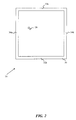
- Figure 2 illustrates the screen wrap barrier used by the system of Figure 1.
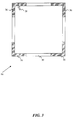
- Figure 3 illustrates a partial screen wrap barrier used by the system of Figure 1.
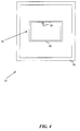
- Figure 4 illustrates the screen wrap barrier used by the system of Figure 1 when an additional window is visible on the computer display.
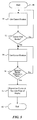
- Figure 5 is a flow chart of the operation of the system of Figure 1.
- the present invention implements a screen wrap barrier to limit the inadvertent wrapping of the cursor as is common in the prior art.
- the system of the present invention permits screen wrapping only after it has determined that a user probably intends to wrap the cursor to the opposite side of the visual display. There are a number of different techniques, described in detail below, by which the system can make such a determination.
- the present invention is embodied in a system 10 shown in the block diagram of Figure 1.
- a central processing unit (CPU) 12 performs the analysis functions that will be described below.
- the CPU 12 can be any number of well known devices.
- the system 10 includes a memory 14, which may comprise both random access memory (RAM) and read-only memory (ROM).
- the memory 14 stores a software program that forms a portion of the system 10.
- the display 16 may be an integral part of the system 10, such as when the system is incorporated into a laptop computer, or may be a stand alone device.
- the system 10 also includes a cursor control device 18 that controls the position of a cursor generated on the display 16.
- the cursor control device 18 may be a mouse, joystick, trackball, keyboard, or the like.
- the present invention is not limited by the specific form of the cursor control device 18.
- the system 10 also includes a command entry device 20, which may be a button on the cursor control device 18 or on a keyboard (not shown).
- the system 10 may also include a second command entry device 21, such as a second button on the cursor control device 18 or on the keyboard (not shown).
- the user can position the cursor at a desired location on the display 16 using the cursor control device 18 and then press the command entry device 20 to activate a computer command associated with the selected location on the display.
- the various components of the system 10 are coupled together by a bus 22, which may carry power as well as data signals.
- a cursor location storage area 24 of the system 10 contains a pointer to the location of the cursor on the display 16.
- the display 16 displays the cursor at the position corresponding to the data within the current location storage area 24.
- the current location storage area 24 may be part of the memory 14.
- the cursor control device 18 generates electrical signals indicative of the desired movement of the cursor.
- the CPU 12 interprets the electrical signals from the cursor control device 18 and alters the current location storage area 24 accordingly. Each time that the CPU alters the current location storage area 24, the position of the cursor on the display 16 is changed in a corresponding fashion.
- the display 16 is generally rectangular in shape and has an electronic border 30 displayed around the edges of the display.
- the border 30 may have the same color as the background graphics displayed on the display 16, or may have a different color so as to make the border 30 visually detectable by the user.
- the advantages of a visible border 30 will be discussed below.
- the system 10 permits the user to determine the color of the border 30.
- the border 30 has two sets of opposing borders, comprising a top border 32a and an opposing bottom border 32b, and a left border 34a and an opposing right border 34b. It should be noted that the border 30 is shown in Figure 2 with exaggerated dimensions relative to the overall size of the display 16 in order to more clearly depict the operation of the present invention.
- the border 30 is a single pixel wide on all four opposing borders 32a, 32b, 34a, and 34b.
- the border 30 can have an arbitrary thickness that may be specified by the user.
- the border 30 may be five pixels wide on all four opposing borders 32a, 32b, 34a, and 34b, or may have a different width for each of the four opposing borders.
- the system 10 causes the movement of the cursor 28 to slow down or stop altogether.
- the system will not permit additional movement of the cursor 28 beyond the border 30 unless a barrier penetration indicator signal is generated.
- the cursor 28 With a one pixel border 30, the cursor 28 can be positioned on the border, but cannot move beyond the border unless the indicator signal is generated. If the border 30 is more than one pixel wide, the system 10 causes the movement of the cursor 28 to slow down or stop within the border. If the indicator signal is generated, the system 10 "lowers the barrier” by deactivating the border 30 and permits the cursor 28 to wrap to the opposite side of the display 16 in a conventional manner.
- the system 10 generates the indicator signal only if it determines that the user probably intends to wrap the cursor 28 to the opposite side of the display 16.
- the generation of the indicator signal may be controlled by a variety of factors. For example, continued efforts by the user to move the cursor 28 beyond the border 30 are interpreted by the system 10 as an indication that the user probably intends to wrap the cursor 28 to the opposite side of the display 16.
- the continued or repetitive effort to move of the cursor 28 against the border 30 is detected by the system 10 by analysis of the electrical signals from the cursor control device 18.
- the continued movement of the cursor 28 against the border 30 may be detected by measuring the time over which the user moves the cursor against the border, or, alternatively, by measuring the distance, based on the continued movement of the cursor against the border, that the cursor 28 would have traveled if no border 30 were in place to serve as a barrier ( i.e. , the distance that the cursor 28 would have moved were it not for the presence of the border 30). If the user continues to move the cursor 28 against the border 30 for a predetermined period of time, the system 10 will generate the indicator signal and permit the cursor 28 to move across the border and then to the opposite side of the display 16.
- the system will generate the indicator signal and permit the cursor 28 to wrap to the opposite side of the display 16.
- the system 10 measures the velocity with which the cursor 28 approaches the border 30 in order to determine whether or not to generate the indicator signal.
- the velocity of the cursor 28 can be determined by measuring the distance over which the cursor is moved in a given time period in response to the user manipulating the cursor control device 18. If the velocity of the cursor 28 is below a predetermined velocity, the system 10 interprets this as an indication that the user actually intends to wrap the cursor 28 to the opposite side of the display 16 because the user is intentionally moving the cursor against the border 30. On the other hand, a high velocity of the cursor 28 against the border 30 indicates that the user may not have intended the cursor 28 to wrap to the opposite side of the display 16.
- the system 10 will prevent the cursor 28 from wrapping unless the indicator signal is generated based on detecting the continued movement of the cursor against the border 30, as described above.
- the velocity can be analyzed such that a velocity that exceeds the predetermined threshold could be interpreted by the system 10 as an indicator that the user actually intends to cause the cursor 28 to wrap to the opposite side of the display 16.
- the system 10 considers this an indication that the user actually intends to wrap the cursor 28 to the opposite side of the display 16. This is similar to the velocity measurement described above. In this embodiment, the velocity is zero at the border 30 and thus the system 10 will generate the indicator signal.
- the acceleration of the cursor 28 may also be used as an indicator of the user's intent. For example, a decreasing acceleration in the vicinity of the border 30 is interpreted by the system 10 as an indication that the user intends to cause the cursor 28 to wrap to the opposite of the display 16. If the acceleration is above a predetermined acceleration, the system 10 interprets this as an indication that the user did not intend to cause the cursor 28 to wrap to the opposite side of the display 16.
- the acceleration may be measured by determining the change in the velocity of the cursor 28 over a given period of time in response to the user manipulating the cursor control device 18. Alternatively, the acceleration can be analyzed such that an acceleration that exceeds the predetermined threshold could be interpreted by the system 10 as an indicator that the user actually intends to cause the cursor 28 to wrap to the opposite side of the display 16.
- the system 10 can analyze the various factors in number of different ways to determine whether or not to generate the indicator signal.
- the system 10 can also use a combination of factors to determine whether or not to generate the indicator signal.
- One such example of a combination of factors is time and distance. If the user continues to manipulate the cursor control device 18 to move the cursor 28 against the border 30 for a predetermined combination of time and distance (i.e. , the distance that the cursor 28 would have moved were it not for the presence of the border 30), the system 10 will generate the indicator signal.
- the user manually generates the indicator signal by manipulating the cursor control device 18 to move the cursor 28 against the border 30 while simultaneously depressing a control switch such as the command entry device 20.
- the simultaneous activation of the command entry device 20 and the movement of the cursor 28 against the border 30 causes the system 10 to generate the indicator signal.
- the system 10 will only allow the cursor 28 to wrap to the opposite side of the display 16 if the user manually generates the indicator signal.
- the system 10 selectively activates and deactivates the border 30 displayed around the edges of the display 16.
- the border 30 is initially deactivated, thus permitting the cursor 28 to wrap from one side of the display to the opposite side without requiring the generation of the indicator signal.
- the indicator signal can serve to deactivate or disable the border 30, while the border is active or enabled whenever the indicator signal is not present.
- the border 30 is defined by an enabled mode, in which the border prevents the wrapping of the cursor 28, and a disabled mode when the presence of the indicator signal permits the wrapping of the cursor 28.
- the system 10 interprets this as an indication that the user inadvertently caused the cursor 28 to wrap. In such a situation, the system 10 will activate the border 30 to prevent further inadvertent screen wrapping.
- the system 10 can be configured to activate the entire border 30 or just the border 34a which the user inadvertently crossed. The user must then subsequently cause the cursor 28 to wrap to the opposite side of the display 16 in one of the manners described above.
- the system 10 deactivates the border 30 to permit the user to wrap the cursor 28 without requiring the generation of the indicator signal. If the user wraps the cursor 28 and does not rewrap the cursor within the first predetermined period of time, the system 10 will not activate the border 30 and will continue to permit the cursor to wrap without requiring the generation of the indicator signal.
- the system 10 interprets this action as an indication that the user actually intended to wrap the cursor 28 to the opposite side of the display 16. In such a situation, the system 10 will not activate the border 30 and will not require the generation of the indicator signal until such time when the user wraps the cursor 28 and rewraps within the first predetermined period of time.
- This embodiment permits the simple wrapping of the cursor 28 without the delay that may be required to generate the indicator signal, but will activate the border 30 if the user's activity indicates that an inadvertent wrapping of the cursor 28 has occurred.
- the system 10 has a plurality of border activation levels that are incrementally altered each time that the cursor 28 wraps within the first predetermined period of time. For example, the system 10 initially deactivates the border 30. However, the first time that the user causes the cursor 28 to wrap from one side of the display 16 to the opposite side of the display, the system 10 activates the border 30 to a first activation level. Each time that the cursor 28 rewraps during the predetermined period of time causes the border 30 to have an incrementally higher border activation level thus making it increasingly more difficult to wrap the cursor 28. The user can penetrate the barrier by causing the system 10 to generate the indicator signal as discussed above.
- the border activation level decreases incrementally for each first predetermined period of time in which the cursor 28 is not wrapped.
- the system 10 can deactivate the border 30 altogether if no subsequent wrapping occurs within the predetermined period of time.
- the system 10 initially starts with the border 30 in an inactive state and activates the border when the user causes the cursor 28 to cross the border the first time.
- the cursor 28 would be prevented from inadvertently rewrapping.
- the system 10 measures a predetermined period of time after the cursor 28 first crosses the border 30. If there is no additional wrapping of the cursor 28 within the predetermined period of time, the system 10 will deactivate the border 30 and return the system to its original state.
- the user may also designate portions of the border 30 as impenetrable so that the designated portion of the border cannot be penetrated even upon continued movement of the cursor 28 against the designated portion of the border.
- the user may designate corners 36, shown in Figure 3, of the border 30 as having no screen wrap capability. Thus, even continued movement of the cursor 28 against the corners 36 will not cause the cursor to wrap to the opposite side of the display 16.
- the corners 36 are displayed in a different color than the border 30 on the display 16 to indicate to the user that no screen wrap will occur in these corner areas.
- the user may designate any portion of the border 30 as impenetrable.
- the user may cause a small window 40 with a border 42 to appear on the display 16, as shown in Figure 4.
- the principles of the system may apply equally to the window 40.
- the border 42 surrounding the window 40 can prevent the user from inadvertently causing the cursor 28 from wrapping from one side of the window 40 to the opposite side.
- the operation of the present invention is illustrated in the flowchart of Figure 5.
- the system 10 begins processing data at start 48.
- step 50 the system 10 gets a current cursor position from the cursor location storage area 24. Techniques for determining the current cursor position are well-known in the art and will not be discussed herein.
- decision 52 the system determines whether the current cursor position is near the border 30. If the current cursor position is not near the border 30, the result of decision 52 is NO and the system 10 returns to step 50. If the current cursor position is near the border 30, the result of decision 52 is YES. In that event, the system 10 gets an updated cursor position in step 54.
- decision 56 the system 10 determines whether or not to generate the indicator signal and permit the cursor 28 to wrap across the border 30.
- This decision step is intended to encompass the broad range of techniques described above, including enabled and disabled modes, variable border activation levels, time, distance, acceleration, velocity, and the like. The factors used in the determination of whether or nor to generate the indicator signal are discussed in detail above.
- the system 10 If the system 10 does not generate the indicator signal, the result of decision 56 is NO, and the system returns to step 54. If the system 10 does generate the indicator signal, the result of decision 56 is YES. In that event, the system 10 repositions the cursor 28 at the opposite edge of the display 16. The system 10 ends the process of indicator in step 60.
- the present invention permits the full use of screen wrapping capabilities available in the prior art without the drawback of inadvertent screen wrapping.
- the present invention describes a variety of factors used to determine whether or not to generate the indicator signal. These techniques may be used individually or in combination, and may be selected by the user to customize the system 10 to the particular user's needs. While the above examples are related to the movement of the cursor 28 through a cursor control device 18 such as a computer mouse, those skilled in the art will readily appreciate that the principles of the present invention are equally applicable to any cursor control device such as a joystick, trackball, keyboard, or the like.
Abstract
Description
- The invention relates generally to a system and method for control of a cursor on a computer display screen.
- Computers have become common in the work place and at home. Early computer systems required extensive knowledge of computer programming to effectively operate the computer. Newer computers have been designed to permit simplified use by those without formal background in computer science. Operating systems, such as the Microsoft® Windows™ operating system provide a graphical environment that can be used by persons with little or no previous experience in the use of computers. Thus, computers have become easier to operate and their use has become more pervasive.
- As computers become even more common, it is important that the operation of the computer become even easier and efficient to operate for the person using the computer. For example, the use of a cursor pointing device, such as a mouse, trackball, or the like, permits the easy manipulation of a cursor on the visual display coupled to the computer. However, there are situations in which even the movement of the cursor with a mouse becomes inefficient. For example, the movement of the cursor from one side of the visual display to the opposite side of the visual display requires extensive manipulation of the mouse. To simplify such movement, some prior art systems permit the movement of the cursor off one side of the visual display and cause the cursor to reappear on the opposite side of the visual display. This technique, known as screen wrapping, can simplify the movement of the cursor.
- While screen wrapping can improve the efficiency of cursor movement, a common complaint of the screen wrap feature is that the cursor sometimes wraps to the opposite side of the visual display when the user did not intend the cursor to wrap. This inadvertent screen wrapping can cause a great deal of frustration, especially when the user must manipulate the cursor near one edge of the visual display. Therefore, it can be appreciated that there is a great need for a system and method for controlling the positioning of a cursor on the computer display that simplifies the positioning of the cursor on the visual display, particularly when moving the cursor near the edges of the visual display.
- The present invention is embodied in a system and method for controlling cursor movement using a display having first and second opposing borders, and means for restricting the movement of the cursor beyond the first border. Signal generation means generate an indicator signal in response to a user effort to move the cursor beyond the first barrier. Wrapping means, enabled by the indicator signal, wrap the cursor from a location in the vicinity of the first border on the display to a location in the vicinity of the second border.
- The first and second borders may be visually detectable to the user. The indicator signal may be generated by a variety of means such as continued movement of the cursor against the first border. The indicator signal may be generated when the cursor is moved against the first border for a predetermined period of time or for a predetermined distance. The indicator signal may be generated in response to the detection of a rate of movement with which the cursor approaches the first border. The rate of movement may be a velocity. The indicator signal may be generated when the velocity is below a predetermined velocity. Alternatively, the detected rate of movement may be an acceleration. The indicator signal may be generated when the acceleration is below a predetermined acceleration. Alternatively, the system may further include a command entry device operable by the user, with the indicator signal beam generated by the user activating the command entry device.
- In an alternative embodiment, the system has selectively enabled wrapping means for wrapping the cursor from a location in the vicinity of the first border to a location in the vicinity of the second border. The wrapping means having enabled mode for restricting movement of the cursor beyond the first border in a disabled mode for permitting the movement of the cursor beyond the first border. The signal generation means generate an indicator signal in response to a user effort to move the cursor beyond the first border with the indicator signal placing the wrapping means in the disabled mode.
- The signal generation means may initially place the wrapping means in a disabled mode with the first crossing of the first border causing the signal generation means to place the wrapping means in the enabled mode. The signal generation means may subsequently return the wrapping means to the disabled mode by the generation of the indicator signal.
- In one embodiment, the indicator signal is generated by the continued movement of the cursor against the first border for a first predetermined period of time. The system may also include adjustment means for increasing the first predetermined period of time following the generation of the indicator signal for a first time such that the indicator signal is generated a second time by continued movement of the cursor against one of the first or second borders for an increased period of time. The adjustment means may increase the first predetermined period of time each time that the cursor recrosses one of the first and second borders within a second predetermined period of time. The adjustment means may also decrease the increased period of time when the indicator signal is not generated within the second predetermined period of time. Similarly, when the indicator signal is generated by continued movement of the cursor against the first border for a first predetermined distance, the system may include adjustment means for increasing the first predetermined distance following the generation of the indicator signal a first time such that the indicator signal is generated a second time by continued movement of the cursor against one of the first and second borders for the increased distance. The adjustment means may increase the first predetermined distance each time that the cursor recrosses one of the first and second borders within a predetermined period of time. The adjustment means can decrease the increased distance when the indicator signal is not generated within the predetermined period of time.
- Figure 1 is a functional block diagram of a system according to the present invention.
- Figure 2 illustrates the screen wrap barrier used by the system of Figure 1.
- Figure 3 illustrates a partial screen wrap barrier used by the system of Figure 1.
- Figure 4 illustrates the screen wrap barrier used by the system of Figure 1 when an additional window is visible on the computer display.
- Figure 5 is a flow chart of the operation of the system of Figure 1.
- The present invention implements a screen wrap barrier to limit the inadvertent wrapping of the cursor as is common in the prior art. The system of the present invention permits screen wrapping only after it has determined that a user probably intends to wrap the cursor to the opposite side of the visual display. There are a number of different techniques, described in detail below, by which the system can make such a determination.
- The present invention is embodied in a
system 10 shown in the block diagram of Figure 1. A central processing unit (CPU) 12 performs the analysis functions that will be described below. TheCPU 12 can be any number of well known devices. Thesystem 10 includes amemory 14, which may comprise both random access memory (RAM) and read-only memory (ROM). Thememory 14 stores a software program that forms a portion of thesystem 10. A computervisual display 16, such as an LED or CRT display, is also included in thesystem 10. Thedisplay 16 may be an integral part of thesystem 10, such as when the system is incorporated into a laptop computer, or may be a stand alone device. - The
system 10 also includes acursor control device 18 that controls the position of a cursor generated on thedisplay 16. Thecursor control device 18 may be a mouse, joystick, trackball, keyboard, or the like. The present invention is not limited by the specific form of thecursor control device 18. Thesystem 10 also includes acommand entry device 20, which may be a button on thecursor control device 18 or on a keyboard (not shown). Thesystem 10 may also include a second command entry device 21, such as a second button on thecursor control device 18 or on the keyboard (not shown). The user can position the cursor at a desired location on thedisplay 16 using thecursor control device 18 and then press thecommand entry device 20 to activate a computer command associated with the selected location on the display. The various components of thesystem 10 are coupled together by abus 22, which may carry power as well as data signals. - A cursor
location storage area 24 of thesystem 10 contains a pointer to the location of the cursor on thedisplay 16. Thedisplay 16 displays the cursor at the position corresponding to the data within the currentlocation storage area 24. The currentlocation storage area 24 may be part of thememory 14. - The
cursor control device 18 generates electrical signals indicative of the desired movement of the cursor. TheCPU 12 interprets the electrical signals from thecursor control device 18 and alters the currentlocation storage area 24 accordingly. Each time that the CPU alters the currentlocation storage area 24, the position of the cursor on thedisplay 16 is changed in a corresponding fashion. - As seen in Figure 2, the
display 16 is generally rectangular in shape and has anelectronic border 30 displayed around the edges of the display. Theborder 30 may have the same color as the background graphics displayed on thedisplay 16, or may have a different color so as to make theborder 30 visually detectable by the user. The advantages of avisible border 30 will be discussed below. In one embodiment, thesystem 10 permits the user to determine the color of theborder 30. - A
cursor 28 is visible on thedisplay 16; the position of thecursor 28 is controlled by the cursor control device 18 (see Figure 1). Theborder 30 has two sets of opposing borders, comprising atop border 32a and an opposingbottom border 32b, and aleft border 34a and an opposingright border 34b. It should be noted that theborder 30 is shown in Figure 2 with exaggerated dimensions relative to the overall size of thedisplay 16 in order to more clearly depict the operation of the present invention. In the presently preferred embodiment, theborder 30 is a single pixel wide on all fouropposing borders border 30 can have an arbitrary thickness that may be specified by the user. For example, theborder 30 may be five pixels wide on all fouropposing borders - As the
cursor 28 is moved using thecursor control device 18 to approach theborder 30, thesystem 10 causes the movement of thecursor 28 to slow down or stop altogether. Thus, even though the user may continue to attempt to move thecursor 28 by manipulating thecursor control device 18, the system will not permit additional movement of thecursor 28 beyond theborder 30 unless a barrier penetration indicator signal is generated. With a onepixel border 30, thecursor 28 can be positioned on the border, but cannot move beyond the border unless the indicator signal is generated. If theborder 30 is more than one pixel wide, thesystem 10 causes the movement of thecursor 28 to slow down or stop within the border. If the indicator signal is generated, thesystem 10 "lowers the barrier" by deactivating theborder 30 and permits thecursor 28 to wrap to the opposite side of thedisplay 16 in a conventional manner. - The
system 10 generates the indicator signal only if it determines that the user probably intends to wrap thecursor 28 to the opposite side of thedisplay 16. The generation of the indicator signal may be controlled by a variety of factors. For example, continued efforts by the user to move thecursor 28 beyond theborder 30 are interpreted by thesystem 10 as an indication that the user probably intends to wrap thecursor 28 to the opposite side of thedisplay 16. The continued or repetitive effort to move of thecursor 28 against theborder 30 is detected by thesystem 10 by analysis of the electrical signals from thecursor control device 18. The continued movement of thecursor 28 against theborder 30 may be detected by measuring the time over which the user moves the cursor against the border, or, alternatively, by measuring the distance, based on the continued movement of the cursor against the border, that thecursor 28 would have traveled if noborder 30 were in place to serve as a barrier (i.e., the distance that thecursor 28 would have moved were it not for the presence of the border 30). If the user continues to move thecursor 28 against theborder 30 for a predetermined period of time, thesystem 10 will generate the indicator signal and permit thecursor 28 to move across the border and then to the opposite side of thedisplay 16. Alternatively, if the user continues to manipulate thecursor control device 18, such that thecursor 28 would have moved more than a predetermined distance beyond theborder 30 were it not for the presence of the border, the system will generate the indicator signal and permit thecursor 28 to wrap to the opposite side of thedisplay 16. - In another embodiment, the
system 10 measures the velocity with which thecursor 28 approaches theborder 30 in order to determine whether or not to generate the indicator signal. The velocity of thecursor 28 can be determined by measuring the distance over which the cursor is moved in a given time period in response to the user manipulating thecursor control device 18. If the velocity of thecursor 28 is below a predetermined velocity, thesystem 10 interprets this as an indication that the user actually intends to wrap thecursor 28 to the opposite side of thedisplay 16 because the user is intentionally moving the cursor against theborder 30. On the other hand, a high velocity of thecursor 28 against theborder 30 indicates that the user may not have intended thecursor 28 to wrap to the opposite side of thedisplay 16. In such a situation, thesystem 10 will prevent thecursor 28 from wrapping unless the indicator signal is generated based on detecting the continued movement of the cursor against theborder 30, as described above. Alternatively, the velocity can be analyzed such that a velocity that exceeds the predetermined threshold could be interpreted by thesystem 10 as an indicator that the user actually intends to cause thecursor 28 to wrap to the opposite side of thedisplay 16. - In yet another alternative, if the user moves the
cursor 28 against theborder 30, stops at the border, and then move the cursor against the border again, thesystem 10 considers this an indication that the user actually intends to wrap thecursor 28 to the opposite side of thedisplay 16. This is similar to the velocity measurement described above. In this embodiment, the velocity is zero at theborder 30 and thus thesystem 10 will generate the indicator signal. - The acceleration of the
cursor 28 may also be used as an indicator of the user's intent. For example, a decreasing acceleration in the vicinity of theborder 30 is interpreted by thesystem 10 as an indication that the user intends to cause thecursor 28 to wrap to the opposite of thedisplay 16. If the acceleration is above a predetermined acceleration, thesystem 10 interprets this as an indication that the user did not intend to cause thecursor 28 to wrap to the opposite side of thedisplay 16. The acceleration may be measured by determining the change in the velocity of thecursor 28 over a given period of time in response to the user manipulating thecursor control device 18. Alternatively, the acceleration can be analyzed such that an acceleration that exceeds the predetermined threshold could be interpreted by thesystem 10 as an indicator that the user actually intends to cause thecursor 28 to wrap to the opposite side of thedisplay 16. - The above examples are presented to indicate the variety of factors that can be used by the
system 10 to determine whether or not to generate the indicator signal. As will be appreciated by those of ordinary skill in the art, thesystem 10 can analyze the various factors in number of different ways to determine whether or not to generate the indicator signal. Thesystem 10 can also use a combination of factors to determine whether or not to generate the indicator signal. One such example of a combination of factors is time and distance. If the user continues to manipulate thecursor control device 18 to move thecursor 28 against theborder 30 for a predetermined combination of time and distance (i.e., the distance that thecursor 28 would have moved were it not for the presence of the border 30), thesystem 10 will generate the indicator signal. - Other techniques may also be used to prevent the inadvertent wrapping of the
cursor 28. In one embodiment, for example, the user manually generates the indicator signal by manipulating thecursor control device 18 to move thecursor 28 against theborder 30 while simultaneously depressing a control switch such as thecommand entry device 20. The simultaneous activation of thecommand entry device 20 and the movement of thecursor 28 against theborder 30 causes thesystem 10 to generate the indicator signal. Thus, thesystem 10 will only allow thecursor 28 to wrap to the opposite side of thedisplay 16 if the user manually generates the indicator signal. - In yet another embodiment, the
system 10 selectively activates and deactivates theborder 30 displayed around the edges of thedisplay 16. For example, in this embodiment theborder 30 is initially deactivated, thus permitting thecursor 28 to wrap from one side of the display to the opposite side without requiring the generation of the indicator signal. The indicator signal can serve to deactivate or disable theborder 30, while the border is active or enabled whenever the indicator signal is not present. Thus, theborder 30 is defined by an enabled mode, in which the border prevents the wrapping of thecursor 28, and a disabled mode when the presence of the indicator signal permits the wrapping of thecursor 28. If the user manipulates thecursor control device 18 to cause thecursor 28 in Figure 2 to cross theborder 34a and appear on the opposite side of the display nearborder 34b, and then causes thecursor 28 to rewrap acrossborder 34b to theopposite border 34a within a predetermined short first period of time, thesystem 10 interprets this as an indication that the user inadvertently caused thecursor 28 to wrap. In such a situation, thesystem 10 will activate theborder 30 to prevent further inadvertent screen wrapping. Thesystem 10 can be configured to activate theentire border 30 or just theborder 34a which the user inadvertently crossed. The user must then subsequently cause thecursor 28 to wrap to the opposite side of thedisplay 16 in one of the manners described above. - After a second predetermined period of time, the
system 10 deactivates theborder 30 to permit the user to wrap thecursor 28 without requiring the generation of the indicator signal. If the user wraps thecursor 28 and does not rewrap the cursor within the first predetermined period of time, thesystem 10 will not activate theborder 30 and will continue to permit the cursor to wrap without requiring the generation of the indicator signal. - In the example above, if the user manipulates the
cursor control device 18 to cause thecursor 28 to cross theborder 34a and appear on the opposite side of the display nearborder 34b, but does not rewrap the cursor within the first predetermined period of time, thesystem 10 interprets this action as an indication that the user actually intended to wrap thecursor 28 to the opposite side of thedisplay 16. In such a situation, thesystem 10 will not activate theborder 30 and will not require the generation of the indicator signal until such time when the user wraps thecursor 28 and rewraps within the first predetermined period of time. This embodiment permits the simple wrapping of thecursor 28 without the delay that may be required to generate the indicator signal, but will activate theborder 30 if the user's activity indicates that an inadvertent wrapping of thecursor 28 has occurred. - In another embodiment, the
system 10 has a plurality of border activation levels that are incrementally altered each time that thecursor 28 wraps within the first predetermined period of time. For example, thesystem 10 initially deactivates theborder 30. However, the first time that the user causes thecursor 28 to wrap from one side of thedisplay 16 to the opposite side of the display, thesystem 10 activates theborder 30 to a first activation level. Each time that thecursor 28 rewraps during the predetermined period of time causes theborder 30 to have an incrementally higher border activation level thus making it increasingly more difficult to wrap thecursor 28. The user can penetrate the barrier by causing thesystem 10 to generate the indicator signal as discussed above. However, for each increase in the border activation level the user must move thecursor 28 against theborder 30 for a greater period of time than with a lower border activation level or move a greater distance (i.e., the distance that thecursor 28 would have moved were it not for the presence of the border 30) if factors such as time and/or distance are used to generate the indicator signal. The border activation level decreases incrementally for each first predetermined period of time in which thecursor 28 is not wrapped. Alternatively, thesystem 10 can deactivate theborder 30 altogether if no subsequent wrapping occurs within the predetermined period of time. - Alternatively, the
system 10 initially starts with theborder 30 in an inactive state and activates the border when the user causes thecursor 28 to cross the border the first time. In this embodiment, thecursor 28 would be prevented from inadvertently rewrapping. Thesystem 10 measures a predetermined period of time after thecursor 28 first crosses theborder 30. If there is no additional wrapping of thecursor 28 within the predetermined period of time, thesystem 10 will deactivate theborder 30 and return the system to its original state. - The user may also designate portions of the
border 30 as impenetrable so that the designated portion of the border cannot be penetrated even upon continued movement of thecursor 28 against the designated portion of the border. For example, the user may designatecorners 36, shown in Figure 3, of theborder 30 as having no screen wrap capability. Thus, even continued movement of thecursor 28 against thecorners 36 will not cause the cursor to wrap to the opposite side of thedisplay 16. In this embodiment, thecorners 36 are displayed in a different color than theborder 30 on thedisplay 16 to indicate to the user that no screen wrap will occur in these corner areas. Alternatively, the user may designate any portion of theborder 30 as impenetrable. - In a graphical environment such as the Windows™ operating system, the user may cause a
small window 40 with aborder 42 to appear on thedisplay 16, as shown in Figure 4. The principles of the system may apply equally to thewindow 40. Theborder 42 surrounding thewindow 40 can prevent the user from inadvertently causing thecursor 28 from wrapping from one side of thewindow 40 to the opposite side. - The operation of the present invention is illustrated in the flowchart of Figure 5. The
system 10 begins processing data atstart 48. Instep 50, thesystem 10 gets a current cursor position from the cursorlocation storage area 24. Techniques for determining the current cursor position are well-known in the art and will not be discussed herein. Indecision 52, the system determines whether the current cursor position is near theborder 30. If the current cursor position is not near theborder 30, the result ofdecision 52 is NO and thesystem 10 returns to step 50. If the current cursor position is near theborder 30, the result ofdecision 52 is YES. In that event, thesystem 10 gets an updated cursor position instep 54. Indecision 56, thesystem 10 determines whether or not to generate the indicator signal and permit thecursor 28 to wrap across theborder 30. This decision step is intended to encompass the broad range of techniques described above, including enabled and disabled modes, variable border activation levels, time, distance, acceleration, velocity, and the like. The factors used in the determination of whether or nor to generate the indicator signal are discussed in detail above. - If the
system 10 does not generate the indicator signal, the result ofdecision 56 is NO, and the system returns to step 54. If thesystem 10 does generate the indicator signal, the result ofdecision 56 is YES. In that event, thesystem 10 repositions thecursor 28 at the opposite edge of thedisplay 16. Thesystem 10 ends the process of indicator instep 60. - Thus, the present invention permits the full use of screen wrapping capabilities available in the prior art without the drawback of inadvertent screen wrapping. The present invention describes a variety of factors used to determine whether or not to generate the indicator signal. These techniques may be used individually or in combination, and may be selected by the user to customize the
system 10 to the particular user's needs. While the above examples are related to the movement of thecursor 28 through acursor control device 18 such as a computer mouse, those skilled in the art will readily appreciate that the principles of the present invention are equally applicable to any cursor control device such as a joystick, trackball, keyboard, or the like. - It is to be understood that even though various embodiments and advantages of the present invention have been set forth in the foregoing description, the above disclosure is illustrative only, and changes may be made in detail, yet remain within the broad principles of the invention. Therefore, the present invention is to be limited only by the appended claims.
Claims (39)
- A system for controlling the movement of a cursor, the system comprising:
a display having first and second opposing borders;
means for restricting the movement of the cursor beyond said first border;
signal generation means for generating an indicator signal in response to a user effort to move the cursor beyond said first border; and
wrapping means, enabled by said indicator signal, for wrapping the cursor from a location in the vicinity of said first border on said display to a location in the vicinity of said second border on said display. - A system for controlling the position of a cursor, comprising:
a display having first and second opposing borders;
selectively enabled wrapping means for wrapping the cursor from a location in the vicinity of said first border on said display to a location in the vicinity of said second border on said display, said wrapping means having an enabled mode for restricting the movement of the cursor beyond said first border and a disabled mode for permitting the movement of the cursor beyond said first border; and
signal generation means for generating an indicator signal in response to a user effort to move the cursor beyond said first border, said indicator signal placing said wrapping means in said disabled mode. - The system of claim 2 wherein said wrapping means are initially placed in said disabled mode by said signal generation means, said signal generation means selectively placing said wrapping means in said enabled mode by the cursor making a first crossing of said first border to wrap the cursor to said second border.
- The system of claim 3 wherein said signal generation means selectively returns said wrapping means to said disabled mode by the generation of said indicator signal.
- The system of claim 2 wherein said wrapping means are initially in said disabled mode and are placed in said enabled mode by said signal generation means upon the cursor making a first crossing of said one border to wrap the cursor to said second border followed by the cursor making a recrossing of said second border to wrap the cursor to said first border.
- The system of claim 5 wherein said signal generation means places said wrapping means in said enabled mode only if said recrossing occurs within a predetermined period of time.
- The system of claim 2, further including detection means for detecting the position of the cursor on said display, said wrapping means initially being in said enabled mode, said signal generation means generating said indicator signal upon said detection means detecting the cursor encountering said first border a first time, detecting no movement of the cursor for a predetermined period of time, and subsequently detecting the cursor to encountering said first border a second time.
- A system for controlling the position of a cursor, comprising:
a display having first and second opposing borders;
selectively enabled barrier means having an enabled mode for restricting the movement of the cursor beyond at least a first portion of said first border and a disabled mode for permitting the movement of the cursor beyond said first portion;
signal generation means for generating, in response to a user effort to move the cursor beyond said first border, an indicator signal to place said barrier means in said disabled mode, said barrier means permitting the cursor to move beyond said first portion to said second border when in said disabled mode and preventing the movement of the cursor beyond said first portion to said second border when in said enabled mode; and
wrapping means for wrapping the cursor from a location in the vicinity of said first portion on said display to a location in the vicinity of said second border on said display when said barrier means is in said disabled mode, whereby the cursor wraps from said first portion to said second border if said barrier means are disabled. - The system of claim 8 wherein said first portion is visually detectable to the user.
- The system of claim 8, further including a second portion of said first border having an impenetrable border that does not have said disabled mode, whereby the cursor cannot cross said second portion.
- The system of any of the preceding claims 1, 2, or 8 wherein said first and second borders are visually detectable to the user.
- The system of any of the preceding claims 1, 2, or 8 wherein said indicator signal is generated by continued movement of the cursor against said first border.
- The system of any of the preceding claims 1, 2, or 8 wherein said indicator signal is generated when the cursor is moved against said first border for a predetermined period of time.
- The system of any of the preceding claims 1, 2, or 8 wherein said indicator signal is generated when the cursor is moved against said first border for a predetermined distance.
- The system of any of the preceding claims 1, 2, or 8 wherein said indicator signal is generated in response to detecting a rate of movement with which the cursor approaches said first border.
- The system of claim 15 wherein said detected rate of movement is a velocity.
- The system of claim 16 wherein said indicator signal is generated by said signal generation means when said velocity is below a predetermined velocity.
- The system of claim 15 wherein said detected rate of movement is an acceleration.
- The system of claim 18 wherein said indicator signal is generated by said signal generation means when said acceleration is below a predetermined acceleration.
- The system of any of the preceding claims 1, 2, or 8 further including a command entry device operable by the user, said indicator signal being generated by the user activating said command entry device.
- The system of any of the preceding claims 1, 2, or 8 wherein said indicator signal is generated by continued movement of the cursor against said first border for a first predetermined period of time, the system further including adjustment means for increasing said first predetermined period of time following the generation of said indicator signal a first time, whereby said indicator signal is generated a second time by continued movement of the cursor against one of said first and second borders for said increased period of time.
- The system of claim 21 wherein said adjustment means increases said first predetermined period of time each time that the cursor recrosses one of said first and second borders within a second predetermined period of time.
- The system of claim 21 wherein said adjustment means decreases said increased period of time when said indicator signal is not generated within a second predetermined period of time.
- The system of any of the preceding claims 1, 2, or 8 wherein said indicator signal is generated by continued movement of the cursor against said first border for a first predetermined distance, the system further including adjustment means for increasing said first predetermined distance following the generation of said indicator signal a first time, whereby said indicator signal is generated a second time by continued movement of the cursor against one of said first and second borders for said increased distance.
- The system of claim 24 wherein said adjustment means increases said first predetermined distance each time that the cursor recrosses one of said first and second borders within a predetermined period of time.
- The system of claim 24 wherein said adjustment means decreases said increased distance when said indicator signal is not generated within a predetermined period of time.
- A method for controlling the position of a cursor on a display coupled to a computer, comprising the steps of:
detecting the position of the cursor on the display;
restricting the movement of the cursor beyond first and second opposing borders on the display;
generating an indicator signal to permit the cursor to move beyond said first border to said second border in response to a user effort to move the cursor beyond said first border; and
in response to said indicator signal, wrapping the cursor from a location in the vicinity of said first border on the display to a location in the vicinity of said second border on the display. - The method of claim 27 wherein said indicator signal is generated by continued movement of the cursor against said first border.
- The method of claim 27 wherein said indicator signal is generated when the cursor is moved against said first border for a predetermined period of time.
- The method of claim 27 wherein said indicator signal is generated when the cursor is moved against said first border for a predetermined distance.
- The method of claim 27 wherein said indicator signal is generated by the user activating a command entry device.
- The method of claim 27 wherein said indicator signal is generated in response to detecting a rate of movement with which the cursor approaches said first border.
- The method of claim 32 wherein said detected rate of movement is a velocity.
- The method of claim 33 wherein said indicator signal is generated by said signal generation means when said velocity is below a predetermined velocity.
- The method of claim 32 wherein said detected rate of movement is an acceleration.
- The method of claim 35 wherein said indicator signal is generated by said signal generation means when said acceleration is below a predetermined acceleration.
- The method of claim 27 wherein said step of restricting the movement of the cursor beyond first and second opposing borders on the display is selectively enabled and has an enabled mode for preventing the movement of the cursor beyond said first border and a disabled mode for permitting the movement of the cursor beyond said first border.
- The method of claim 37 wherein said step of restricting the movement of the cursor beyond first and second opposing borders on the display is initially placed in said disabled mode, said step of restricting the movement of the cursor beyond first and second opposing borders on the display entering said enabled mode by the cursor making a first crossing of said first border to wrap the cursor to said second border.
- The method of claim 37 wherein said step of generating said indicator signal selectively returns said step of preventing the movement of the cursor beyond first and second opposing borders on the display said disabled mode by the generation of said indicator signal.
Applications Claiming Priority (2)
| Application Number | Priority Date | Filing Date | Title |
|---|---|---|---|
| US206543 | 1994-03-04 | ||
| US08/206,543 US5929840A (en) | 1994-03-04 | 1994-03-04 | System and method for computer cursor control |
Publications (2)
| Publication Number | Publication Date |
|---|---|
| EP0670541A2 true EP0670541A2 (en) | 1995-09-06 |
| EP0670541A3 EP0670541A3 (en) | 1997-02-12 |
Family
ID=22766853
Family Applications (1)
| Application Number | Title | Priority Date | Filing Date |
|---|---|---|---|
| EP95103086A Withdrawn EP0670541A3 (en) | 1994-03-04 | 1995-03-03 | System and method for computer cursor control. |
Country Status (3)
| Country | Link |
|---|---|
| US (1) | US5929840A (en) |
| EP (1) | EP0670541A3 (en) |
| JP (1) | JPH0836478A (en) |
Cited By (3)
| Publication number | Priority date | Publication date | Assignee | Title |
|---|---|---|---|---|
| WO1998021645A1 (en) * | 1996-11-12 | 1998-05-22 | Legaltech, Inc. | Computer input device and controller therefor |
| FR2860308A1 (en) * | 2003-09-26 | 2005-04-01 | Inst Nat Rech Inf Automat | CURSOR POSITION MODULATION IN VIDEO DATA FOR COMPUTER SCREEN |
| EP2044505A2 (en) * | 2006-07-10 | 2009-04-08 | Danger, Inc. | Trackball system and method for a mobile data processing device |
Families Citing this family (31)
| Publication number | Priority date | Publication date | Assignee | Title |
|---|---|---|---|---|
| US6867790B1 (en) * | 1996-08-09 | 2005-03-15 | International Business Machines Corporation | Method and apparatus to conditionally constrain pointer movement on a computer display using visual cues, controlled pointer speed and barriers on the display which stop or restrict pointer movement |
| US6920619B1 (en) * | 1997-08-28 | 2005-07-19 | Slavoljub Milekic | User interface for removing an object from a display |
| USRE43318E1 (en) * | 1997-08-28 | 2012-04-17 | Flatworld Interactives, Llc | User interface for removing an object from a display |
| US6295049B1 (en) * | 1999-03-03 | 2001-09-25 | Richard T. Minner | Computer system utilizing graphical user interface with hysteresis to inhibit accidental selection of a region due to unintended cursor motion and method |
| FR2795997B1 (en) * | 1999-07-05 | 2001-10-19 | Cit Alcatel | METHOD FOR MANUFACTURING AN INDEX GRADIENT PLASTIC OPTICAL FIBER |
| JP4501209B2 (en) | 2000-03-08 | 2010-07-14 | ソニー株式会社 | Information processing apparatus, information processing method, and remote control commander |
| US20020084981A1 (en) * | 2000-11-14 | 2002-07-04 | Flack James F. | Cursor navigation system and method for a display |
| US6819313B2 (en) * | 2001-03-08 | 2004-11-16 | International Business Machines Corporation | User interactive cursor control in a computer controlled display system with supplemental mouse lighting to aid in cursor positioning |
| US7187049B2 (en) * | 2002-05-13 | 2007-03-06 | Micron Technology, Inc. | Data download to imager chip using image sensor as a receptor |
| US20040070616A1 (en) * | 2002-06-02 | 2004-04-15 | Hildebrandt Peter W. | Electronic whiteboard |
| US7454707B2 (en) * | 2002-09-30 | 2008-11-18 | Canon Kabushiki Kaisha | Image editing method, image editing apparatus, program for implementing image editing method, and recording medium recording program |
| US7761814B2 (en) * | 2004-09-13 | 2010-07-20 | Microsoft Corporation | Flick gesture |
| US8013837B1 (en) * | 2005-10-11 | 2011-09-06 | James Ernest Schroeder | Process and apparatus for providing a one-dimensional computer input interface allowing movement in one or two directions to conduct pointer operations usually performed with a mouse and character input usually performed with a keyboard |
| US7782302B2 (en) * | 2006-07-10 | 2010-08-24 | Microsoft Corporation | Trackball for a mobile device |
| GB2443010B (en) * | 2006-10-10 | 2009-09-02 | Promethean Technologies Group | Interactive display system |
| US10504285B2 (en) * | 2007-09-26 | 2019-12-10 | Autodesk, Inc. | Navigation system for a 3D virtual scene |
| US8686991B2 (en) | 2007-09-26 | 2014-04-01 | Autodesk, Inc. | Navigation system for a 3D virtual scene |
| JP5707015B2 (en) * | 2007-09-27 | 2015-04-22 | 株式会社日立メディコ | Information display device |
| US9244587B2 (en) * | 2008-01-30 | 2016-01-26 | Gvbb Holdings S.A.R.L. | Pointer controlling apparatus, method thereof, and pointer controlling program to prevent erroneous operation |
| US8176434B2 (en) * | 2008-05-12 | 2012-05-08 | Microsoft Corporation | Virtual desktop view scrolling |
| US8806381B2 (en) * | 2009-11-18 | 2014-08-12 | International Business Machines Corporation | Method and system to improve GUI use efficiency |
| JP2012156797A (en) * | 2011-01-26 | 2012-08-16 | Sony Corp | Image processing apparatus and image processing method |
| US20140168126A1 (en) * | 2012-12-14 | 2014-06-19 | Jeffrey N. Yu | Dynamic border control systems and methods |
| US20150074564A1 (en) * | 2013-09-10 | 2015-03-12 | Lenovo (Singapore) Pte. Ltd. | Feedback for cursor location in multiple monitor device contexts |
| US10664162B2 (en) * | 2013-11-18 | 2020-05-26 | Red Hat, Inc. | Multiple display management |
| EP2887184A1 (en) * | 2013-12-23 | 2015-06-24 | Movea | Air pointer with improved user experience |
| GB201408258D0 (en) * | 2014-05-09 | 2014-06-25 | British Sky Broadcasting Ltd | Television display and remote control |
| US20160239085A1 (en) | 2015-02-18 | 2016-08-18 | Lenovo (Singapore) Pte, Ltd. | Force indication of a boundary |
| US10423293B2 (en) * | 2015-11-25 | 2019-09-24 | International Business Machines Corporation | Controlling cursor motion |
| US11093101B2 (en) * | 2018-06-14 | 2021-08-17 | International Business Machines Corporation | Multiple monitor mouse movement assistant |
| CN111447484B (en) * | 2020-03-31 | 2022-04-08 | 北京小米移动软件有限公司 | Loading method and device of electronic program guide EPG and storage medium |
Citations (2)
| Publication number | Priority date | Publication date | Assignee | Title |
|---|---|---|---|---|
| DE3632601A1 (en) * | 1985-09-27 | 1987-04-23 | Olympus Optical Co | DEVICE FOR DISPLAYING A POSITION BRAND ON SEVERAL SCREENS |
| US5208906A (en) * | 1988-12-30 | 1993-05-04 | Chipsoft Ca, Corp. | Method and apparatus for representing bordered areas of a generic form with records |
Family Cites Families (4)
| Publication number | Priority date | Publication date | Assignee | Title |
|---|---|---|---|---|
| US5195179A (en) * | 1986-01-29 | 1993-03-16 | Hitachi, Ltd. | Coordinate input apparatus |
| JP2784032B2 (en) * | 1989-04-04 | 1998-08-06 | 株式会社日立製作所 | Screen display switching method and screen display switching device |
| JPH02294687A (en) * | 1989-05-10 | 1990-12-05 | Fujitsu Ltd | Cursor controller |
| US5263134A (en) * | 1989-10-25 | 1993-11-16 | Apple Computer, Inc. | Method and apparatus for controlling computer displays by using a two dimensional scroll palette |
-
1994
- 1994-03-04 US US08/206,543 patent/US5929840A/en not_active Expired - Lifetime
-
1995
- 1995-03-03 JP JP7044412A patent/JPH0836478A/en not_active Withdrawn
- 1995-03-03 EP EP95103086A patent/EP0670541A3/en not_active Withdrawn
Patent Citations (2)
| Publication number | Priority date | Publication date | Assignee | Title |
|---|---|---|---|---|
| DE3632601A1 (en) * | 1985-09-27 | 1987-04-23 | Olympus Optical Co | DEVICE FOR DISPLAYING A POSITION BRAND ON SEVERAL SCREENS |
| US5208906A (en) * | 1988-12-30 | 1993-05-04 | Chipsoft Ca, Corp. | Method and apparatus for representing bordered areas of a generic form with records |
Cited By (6)
| Publication number | Priority date | Publication date | Assignee | Title |
|---|---|---|---|---|
| WO1998021645A1 (en) * | 1996-11-12 | 1998-05-22 | Legaltech, Inc. | Computer input device and controller therefor |
| US5870079A (en) * | 1996-11-12 | 1999-02-09 | Legaltech, Inc. | Computer input device and controller therefor |
| FR2860308A1 (en) * | 2003-09-26 | 2005-04-01 | Inst Nat Rech Inf Automat | CURSOR POSITION MODULATION IN VIDEO DATA FOR COMPUTER SCREEN |
| WO2005031556A1 (en) * | 2003-09-26 | 2005-04-07 | Inria Institut National De Recherche En Informatique Et En Automatique | Modulation of cursor position in video data for a computer screen |
| EP2044505A2 (en) * | 2006-07-10 | 2009-04-08 | Danger, Inc. | Trackball system and method for a mobile data processing device |
| EP2044505A4 (en) * | 2006-07-10 | 2013-01-09 | Microsoft Corp | Trackball system and method for a mobile data processing device |
Also Published As
| Publication number | Publication date |
|---|---|
| JPH0836478A (en) | 1996-02-06 |
| EP0670541A3 (en) | 1997-02-12 |
| US5929840A (en) | 1999-07-27 |
Similar Documents
| Publication | Publication Date | Title |
|---|---|---|
| US5929840A (en) | System and method for computer cursor control | |
| US5508717A (en) | Computer pointing device with dynamic sensitivity | |
| US5611060A (en) | Auto-scrolling during a drag and drop operation | |
| US5943052A (en) | Method and apparatus for scroll bar control | |
| US6567109B1 (en) | Automatic target enlargement for simplified selection | |
| JP3297365B2 (en) | Method, computer system and selection system for improving object selection on a computer display by providing stickiness characteristics to a cursor control | |
| US5053758A (en) | Touchscreen control panel with sliding touch control | |
| US6025841A (en) | Method for managing simultaneous display of multiple windows in a graphical user interface | |
| US5821930A (en) | Method and system for generating a working window in a computer system | |
| US5956019A (en) | Touch-pad cursor control device | |
| US6411283B1 (en) | Computer touch screen adapted to facilitate selection of features at edge of screen | |
| US5396590A (en) | Non-modal method and apparatus for manipulating graphical objects | |
| US5568604A (en) | Method and system for generating a working window in a computer system | |
| EP1052566A1 (en) | Graphical user interface | |
| US5686937A (en) | User interface system and method for creating and removing a scrolling icon from a display based upon user past and present interaction with the icon | |
| US20040261038A1 (en) | Computer interface having a virtual single-layer mode for viewing overlapping objects | |
| JPH04276821A (en) | Operating method for computer display control system and computer display system, control method in computer display system and computer display control apparatus | |
| JPH06314167A (en) | Adaptive touch recognition | |
| KR20100085957A (en) | Pointer controlling apparatus | |
| US5646647A (en) | Automatic parking of cursor in a graphical environment | |
| KR960010927B1 (en) | Touch screen control panel | |
| US8140972B2 (en) | Sticky functionality | |
| JPH02242323A (en) | Method and device for selecting pop-up menu | |
| JP3064123B2 (en) | Information processing device and input control device | |
| US20070198953A1 (en) | Target acquisition |
Legal Events
| Date | Code | Title | Description |
|---|---|---|---|
| PUAI | Public reference made under article 153(3) epc to a published international application that has entered the european phase |
Free format text: ORIGINAL CODE: 0009012 |
|
| AK | Designated contracting states |
Kind code of ref document: A2 Designated state(s): DE FR GB |
|
| RIN1 | Information on inventor provided before grant (corrected) |
Inventor name: MCROBERT, ALAN W. Inventor name: CLAFIN, ANTHONY R. Inventor name: ROBERTSON, KENNETH R. Inventor name: HENDERSON, PAUL E. JR. Inventor name: BREWER, TIMOTHY T. |
|
| PUAL | Search report despatched |
Free format text: ORIGINAL CODE: 0009013 |
|
| AK | Designated contracting states |
Kind code of ref document: A3 Designated state(s): DE FR GB |
|
| 17P | Request for examination filed |
Effective date: 19970807 |
|
| STAA | Information on the status of an ep patent application or granted ep patent |
Free format text: STATUS: THE APPLICATION IS DEEMED TO BE WITHDRAWN |
|
| 18D | Application deemed to be withdrawn |
Effective date: 19991001 |