EP0661867B1 - Scan type laser marking device - Google Patents
Scan type laser marking device Download PDFInfo
- Publication number
- EP0661867B1 EP0661867B1 EP94119056A EP94119056A EP0661867B1 EP 0661867 B1 EP0661867 B1 EP 0661867B1 EP 94119056 A EP94119056 A EP 94119056A EP 94119056 A EP94119056 A EP 94119056A EP 0661867 B1 EP0661867 B1 EP 0661867B1
- Authority
- EP
- European Patent Office
- Prior art keywords
- mark
- marking device
- scan type
- coordinate
- laser marking
- Prior art date
- Legal status (The legal status is an assumption and is not a legal conclusion. Google has not performed a legal analysis and makes no representation as to the accuracy of the status listed.)
- Expired - Lifetime
Links
Images


Classifications
-
- B—PERFORMING OPERATIONS; TRANSPORTING
- B23—MACHINE TOOLS; METAL-WORKING NOT OTHERWISE PROVIDED FOR
- B23K—SOLDERING OR UNSOLDERING; WELDING; CLADDING OR PLATING BY SOLDERING OR WELDING; CUTTING BY APPLYING HEAT LOCALLY, e.g. FLAME CUTTING; WORKING BY LASER BEAM
- B23K15/00—Electron-beam welding or cutting
-
- H—ELECTRICITY
- H04—ELECTRIC COMMUNICATION TECHNIQUE
- H04N—PICTORIAL COMMUNICATION, e.g. TELEVISION
- H04N1/00—Scanning, transmission or reproduction of documents or the like, e.g. facsimile transmission; Details thereof
- H04N1/04—Scanning arrangements, i.e. arrangements for the displacement of active reading or reproducing elements relative to the original or reproducing medium, or vice versa
- H04N1/047—Detection, control or error compensation of scanning velocity or position
-
- B—PERFORMING OPERATIONS; TRANSPORTING
- B23—MACHINE TOOLS; METAL-WORKING NOT OTHERWISE PROVIDED FOR
- B23K—SOLDERING OR UNSOLDERING; WELDING; CLADDING OR PLATING BY SOLDERING OR WELDING; CUTTING BY APPLYING HEAT LOCALLY, e.g. FLAME CUTTING; WORKING BY LASER BEAM
- B23K26/00—Working by laser beam, e.g. welding, cutting or boring
- B23K26/08—Devices involving relative movement between laser beam and workpiece
- B23K26/083—Devices involving movement of the workpiece in at least one axial direction
- B23K26/0838—Devices involving movement of the workpiece in at least one axial direction by using an endless conveyor belt
-
- G—PHYSICS
- G06—COMPUTING; CALCULATING OR COUNTING
- G06K—GRAPHICAL DATA READING; PRESENTATION OF DATA; RECORD CARRIERS; HANDLING RECORD CARRIERS
- G06K15/00—Arrangements for producing a permanent visual presentation of the output data, e.g. computer output printers
- G06K15/02—Arrangements for producing a permanent visual presentation of the output data, e.g. computer output printers using printers
- G06K15/028—Arrangements for producing a permanent visual presentation of the output data, e.g. computer output printers using printers by thermal printers
- G06K15/029—Arrangements for producing a permanent visual presentation of the output data, e.g. computer output printers using printers by thermal printers using optical beams
-
- G—PHYSICS
- G06—COMPUTING; CALCULATING OR COUNTING
- G06K—GRAPHICAL DATA READING; PRESENTATION OF DATA; RECORD CARRIERS; HANDLING RECORD CARRIERS
- G06K15/00—Arrangements for producing a permanent visual presentation of the output data, e.g. computer output printers
- G06K15/02—Arrangements for producing a permanent visual presentation of the output data, e.g. computer output printers using printers
- G06K15/12—Arrangements for producing a permanent visual presentation of the output data, e.g. computer output printers using printers by photographic printing, e.g. by laser printers
- G06K15/1228—Arrangements for producing a permanent visual presentation of the output data, e.g. computer output printers using printers by photographic printing, e.g. by laser printers involving the fast moving of a light beam in two directions
-
- H—ELECTRICITY
- H04—ELECTRIC COMMUNICATION TECHNIQUE
- H04N—PICTORIAL COMMUNICATION, e.g. TELEVISION
- H04N1/00—Scanning, transmission or reproduction of documents or the like, e.g. facsimile transmission; Details thereof
- H04N1/04—Scanning arrangements, i.e. arrangements for the displacement of active reading or reproducing elements relative to the original or reproducing medium, or vice versa
- H04N1/113—Scanning arrangements, i.e. arrangements for the displacement of active reading or reproducing elements relative to the original or reproducing medium, or vice versa using oscillating or rotating mirrors
-
- H—ELECTRICITY
- H04—ELECTRIC COMMUNICATION TECHNIQUE
- H04N—PICTORIAL COMMUNICATION, e.g. TELEVISION
- H04N1/00—Scanning, transmission or reproduction of documents or the like, e.g. facsimile transmission; Details thereof
- H04N1/04—Scanning arrangements, i.e. arrangements for the displacement of active reading or reproducing elements relative to the original or reproducing medium, or vice versa
- H04N1/12—Scanning arrangements, i.e. arrangements for the displacement of active reading or reproducing elements relative to the original or reproducing medium, or vice versa using the sheet-feed movement or the medium-advance or the drum-rotation movement as the slow scanning component, e.g. arrangements for the main-scanning
-
- H—ELECTRICITY
- H04—ELECTRIC COMMUNICATION TECHNIQUE
- H04N—PICTORIAL COMMUNICATION, e.g. TELEVISION
- H04N2201/00—Indexing scheme relating to scanning, transmission or reproduction of documents or the like, and to details thereof
- H04N2201/04—Scanning arrangements
- H04N2201/0402—Arrangements not specific to a particular one of the scanning methods covered by groups H04N1/04 - H04N1/207
- H04N2201/0416—Performing a pre-scan
-
- H—ELECTRICITY
- H04—ELECTRIC COMMUNICATION TECHNIQUE
- H04N—PICTORIAL COMMUNICATION, e.g. TELEVISION
- H04N2201/00—Indexing scheme relating to scanning, transmission or reproduction of documents or the like, and to details thereof
- H04N2201/04—Scanning arrangements
- H04N2201/047—Detection, control or error compensation of scanning velocity or position
- H04N2201/04701—Detection of scanning velocity or position
- H04N2201/0471—Detection of scanning velocity or position using dedicated detectors
-
- H—ELECTRICITY
- H04—ELECTRIC COMMUNICATION TECHNIQUE
- H04N—PICTORIAL COMMUNICATION, e.g. TELEVISION
- H04N2201/00—Indexing scheme relating to scanning, transmission or reproduction of documents or the like, and to details thereof
- H04N2201/04—Scanning arrangements
- H04N2201/047—Detection, control or error compensation of scanning velocity or position
- H04N2201/04701—Detection of scanning velocity or position
- H04N2201/04731—Detection of scanning velocity or position in the sub-scan direction
-
- H—ELECTRICITY
- H04—ELECTRIC COMMUNICATION TECHNIQUE
- H04N—PICTORIAL COMMUNICATION, e.g. TELEVISION
- H04N2201/00—Indexing scheme relating to scanning, transmission or reproduction of documents or the like, and to details thereof
- H04N2201/04—Scanning arrangements
- H04N2201/047—Detection, control or error compensation of scanning velocity or position
- H04N2201/04701—Detection of scanning velocity or position
- H04N2201/04743—Detection of scanning velocity or position by detecting the image directly
-
- H—ELECTRICITY
- H04—ELECTRIC COMMUNICATION TECHNIQUE
- H04N—PICTORIAL COMMUNICATION, e.g. TELEVISION
- H04N2201/00—Indexing scheme relating to scanning, transmission or reproduction of documents or the like, and to details thereof
- H04N2201/04—Scanning arrangements
- H04N2201/047—Detection, control or error compensation of scanning velocity or position
- H04N2201/04753—Control or error compensation of scanning position or velocity
- H04N2201/04755—Control or error compensation of scanning position or velocity by controlling the position or movement of a scanning element or carriage, e.g. of a polygonal mirror, of a drive motor
-
- H—ELECTRICITY
- H04—ELECTRIC COMMUNICATION TECHNIQUE
- H04N—PICTORIAL COMMUNICATION, e.g. TELEVISION
- H04N2201/00—Indexing scheme relating to scanning, transmission or reproduction of documents or the like, and to details thereof
- H04N2201/04—Scanning arrangements
- H04N2201/047—Detection, control or error compensation of scanning velocity or position
- H04N2201/04753—Control or error compensation of scanning position or velocity
- H04N2201/04789—Control or error compensation of scanning position or velocity in the main-scan direction
-
- H—ELECTRICITY
- H04—ELECTRIC COMMUNICATION TECHNIQUE
- H04N—PICTORIAL COMMUNICATION, e.g. TELEVISION
- H04N2201/00—Indexing scheme relating to scanning, transmission or reproduction of documents or the like, and to details thereof
- H04N2201/04—Scanning arrangements
- H04N2201/047—Detection, control or error compensation of scanning velocity or position
- H04N2201/04753—Control or error compensation of scanning position or velocity
- H04N2201/04791—Control or error compensation of scanning position or velocity in the sub-scan direction
Definitions
- This invention relates to laser marking devices which apply a laser beam to an object to form marks such as characters and symbols on it, and more particularly a scan type laser marking device.
- a scan type laser marking device outputs a laser beam in such a manner that the laser beam is applied to the surface of an object such as an article or product while being deflected in a predetermined area in a scanning mode, for instance shown in Unexamined Japanese Patent Publication Sho. JP-A-1-11083.
- a scan type laser marking device of this type a conveyor is provided to convey objects successively. In this case, it is necessary to take the speed of the conveyor into consideration to determine the scanning speed; that is, it is necessary to accomplish the marking operation while the object is in the laser beam radiation area. However, it is difficult to set the scanning speed to a suitable value so that the laser beam irradiation time is fully utilized, and the scanning speed is generally higher than required.
- the spot of the laser beam is shifted from the aimed position because of a delay in response of the optical system.
- patterns such as characters and graphic forms marked on the object are blurred; that is, they are low in picture quality.
- the laser beam application time per area is decreased, and therefore it is necessary to increase the output of the laser.
- Another laser marking device has a laser source such an for instance a CO 2 laser. Roughly stated, the device operates as follows: The output laser beam of the CO 2 laser is applied to the surface of an object through a scanner made up of a galvano-mirror. Under this condition, the beam deflecting operation of the scanner is controlled with the aid of a computer so that a graphic form is described on the surface of the object.
- the conventional laser marking device of this type operates as follows: When the object 181, being conveyed by the conveying stand, comes under a marking head 180, the conveying stand 141 is stopped. Under this condition, the output laser beam of the marking head 180 is deflected both in the direction of X-axis and in the direction of Y-axis while being applied to the surface of the object 181.
- the object In the case of the conventional laser marking device, the object must remain at rest while the mark is being formed on it. Therefore, in the case where it is required to put a pattern on a plurality of objects 181 one after another which are conveyed by the conveying stand 141, it is necessary to stop the conveying stand 141 for every object. This means that the device is low in productive efficiency.
- an object of the invention is to solve the above-described problem. More specifically, an object of the invention is to provide a scan type laser marking device in which the scanning speed can be decreased as far as it permits a necessary marking operation; that is, it can be set to a suitable value. This object is solved by the subject-matter of the claims 1, 3 or 5.
- the present invention provides a scan type laser marking device which scans the surface of an object conveyed in a predetermined area and applies a laser beam to the surface of the object to form a mark on the surface of the object
- the scan type laser marking device comprising: an area storing section for storing the area; a start point coordinate storing section for storing coordinates of an irradiation start point in the area, the irradiation start point being located upstream relating to the direction of conveyance of the object; an end point coordinate storing section for storing coordinates of an irradiation end point in the area, the irradiation being located downstream relating to the direction of conveyance of the object; a mark reference point section for storing the coordinates of a reference point on the mark; and speed setting means for setting scanning speeds so that a marking operation is started when the mark reference point reaches the irradiation start point, and is ended when the mark reference point reaches the irradiation end point.
- the invetion provides a scan type laser marking device comprising: measuring means for measuring a time which is required for performing a marking operation with a reference scanning speed; and scanning speed calculating means for utilizing the time thus measured, a marking target time, and the reference scanning speed to calculate individual scanning speeds which are to be actually used.
- the invention provides a scan type laser marking device comprising: a maximum area storing section for storing a maximum area where a marking operation is allowed; a target area storing section for storing a target area smaller than the maximum area; and speed setting means for setting a scanning speed with which a marking operation is accomplished within the target area.
- mark reference points O 1 , O 2 and O 3 when applicable
- mark reference points O 1 , O 2 and O 3 when applicable
- the coordinates of an irradiation start point S T in a target area A T which is located on the upstream side of the latter as viewed in the direction of movement of the workpiece W are stored, and the coordinates of an irradiation end point E in the target area A T which is located on the downstream side of the latter are also stored.
- the workpiece W is conveyed in the direction of the arrow B.
- a scanning speed is so determined that when the mark reference point O 1 located upstream as viewed in the direction of movement of the workpiece W reaches the irradiation start point S T , a marking operation is started.
- the mark reference point O 3 located downstream reaches the irradiation end point E, the marking operation is ended.
- the marking operation is performed while the workpiece W moves a relatively long distance (a + b), and accordingly the scanning speed can be made slower than in the case where a scanning speed is fixedly set to a high value.
- the individual scanning speeds S can be obtained according to the above-described target time T, reference scanning speed S 0 , and measured time T 0 .
- the target time T depends on the mark; however, by increasing the target time T as much as permitted, the individual scanning speeds S can be made lower than the reference scanning speed S 0 .
- the maximum area A M including the target area A T , is larger than the latter.
- the laser beam is applied obliquely, and therefore the distance from the spot of the laser beam is relatively long. Accordingly, in the peripheral portion of the maximum area, outside the target area A T , the laser beam is not sufficiently focused, and the laser beam energy per unitary area is small.
- the scanning speed should be so determined that the marking operation is accomplished within the time which is required for the workpiece W to pass through the target area A T .
- the scanning speed can be relatively low, and the marking operation can be achieved in the maximum area A M although the conveying speed of the workpiece W involves some variation.
- the laser marking device of the invention scanning the surface of the object with the laser beam is carried out with the object being moved on.
- the displacement data on the displacement of the object is applied to the control system every moment.
- the coordinate data provided by the coordinate producing means represent the relative coordinates of dots with respect to the object which is at rest.
- the optical scanning system should deflect the laser beam in the direction of X-axis (or Y-axis) according to the coordinate data from the coordinate producing means
- the X-axis coordinate value (or Y-axis coordinate value) of each of the dots forming the graphic pattern is corrected as much as the displacement of the object in the direction of X-axis (or Y-axis), so that the relative coordinate system on the object is transformed into an absolute coordinate system.
- coordinate data (corrected coordinate data) of the absolute coordinate system a graphic pattern can be accurately described on an object which is in motion.
- the laser marking device of the invention With the laser marking device of the invention, a graphic form can be accurately described on an object which is in motion. Thus, the device shows a high productive efficiency in marking a plurality of objects successively.
- FIGS. 1 through 3D show a scan type laser marking device, which constitutes a first embodiment of the invention.
- reference numeral 1 designates a laser oscillator which is for instance a CO 2 laser.
- the laser oscillator 1 when energized by a drive power source circuit 2, oscillates to emit a laser beam LB.
- the laser beam LB is reflected by a pair of galvano-mirrors 3a and 3b, and applied through a condenser lens 4 to the surface of a workpiece (or an object) W.
- the galvano-mirrors 3a and 3b form a scanning optical system 3, and is driven by an optical system driving device 5 which is made up of a pair of galvano-meters 5a and 5b.
- the laser beam LB while being deflected in a maximum irradiation area A M (hereinafter referred to as "a maximum area A M ", when applicable) in a scanning mode, is applied to the surface of the workpiece W which is being conveyed, so that the latter W is marked by the energy of the laser beam.
- the workpiece W is conveyed in the direction of the arrow B into the maximum area A M by a conveying device 6 such as a conveyor.
- a workpiece detector 7 When the workpiece W reaches the maximum area A M in this manner, it is detected by a workpiece detector 7.
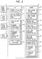
- the laser marking device comprises: a control device 8 made up of a microcomputer; and an input device 9.
- the control device 8 includes a CPU 10, and memory means 20.
- the CPU 10 includes a control section 11, relative coordinate calculating means 12, speed setting means 13, and timer means (or measuring means) 14.
- the memory means 20 includes a mark storing section 27, a mark reference point storing section 21, a maximum area storing section 22, an target area storing section 23, a start point coordinate storing section 24, an end point coordinate storing section 25, and a scanning speed storing section 26.
- the control device 8 is coupled through an interface (not shown) to the input device 9.
- the coordinates representing the configuration of a mark M as shown in FIG. 3B, and the coordinates of reference points O 1 , O 2 and O 3 of the mark M have been stored in the mark storing section 27 and the reference point storing section 21, respectively, being inputted by the input device 9 shown in FIG. 2.
- the coordinates of the maximum area A M has been stored in the maximum area storing section 22.
- a target area A T has been stored in the target area storing section 23.
- the target area is included in the maximum area A M , thus being smaller than the latter A M .
- the target area A T is for instance a square c ⁇ c, and it is coaxial with the maximum area A M .
- the laser beam is substantially accurately focused on the workpiece, so that the mark formed on the latter is high in picture quality.
- the reference scanning speed S 0 is set, for instance, to the maximum scanning speed of the marking device.
- the individual scanning speeds S are determined according to the kind of workpiece to be handled; that is, according to a mark to be described on the workpiece, and are set by the speed setting means 13 as described later.
- the relative coordinate calculating means 12 operates to transform the coordinates of the mark M and the mark reference points O 1 , O 2 and O 3 shown in FIG. 3B, which are read out of the mark storing section 27 and the mark reference point storing section 21 respectively, into relative coordinates which are irradiated by the laser beam in the target area A T as shown in FIG. 3C. This coordinate transformation is carried out with the conveying speed v of the conveying device 6 (FIG. 1) taken into account.
- the control section 11 shown in FIG. 2 operates to control the drive power source circuit 2 and the optical system driving device 5 so that the laser beam LB (FIG. 1) is applied to positions corresponding to the above-described relative coordinates with the individual scanning speed S or with the reference scanning speed S 0 .
- the speed setting means 13 has scanning speed calculating means 13a for calculating the individual scanning speeds S. That is, the speed setting means 13 operates to determine the individual scanning speeds S so that the marking operation is started when the mark reference point O 1 located upstream as viewed in the direction of conveyance in FIG. 3C reaches the irradiation start point S T , and it is ended when the mark reference point O 3 located downstream as viewed in the same direction reaches the irradiation end point E.
- the speed setting means 13 (FIG. 2) determines the individual scanning speeds S so that the marking operation is accomplished while the workpiece is in the target area A T instead of the maximum area A M .
- the reference scanning speed S 0 is read from the scanning speed storing section 26; and with the optical system driving device 5 operated, the time T 0 is measured which is required for describing the mark on the workpiece with the reference scanning speed S 0 .
- the time T 0 is measured by the timer means 14.
- the laser oscillator 1 preferably output no laser beam; however, it may output the laser beam as the case may be.
- the marking operation is carried out during the period of time which elapses from the time instant that the upstream-side mark reference point O 1 of the workpiece W reaches the irradiation start point S T until the downstream-side mark reference point O 3 comes to the irradiation end point E.
- Equation (1) is established between the above-described target time T, measured time T 0 , individual scanning speed S, and reference scanning speed S 0 :
- S ⁇ T S 0 ⁇ T 0
- the scanning speed calculating means 13a shown in FIG. 2 calculates the individual scanning speeds S according to the above-descried Equations (1) and (2).
- the individual scanning speeds S thus calculated are stored in an individual scanning speed storing section 13b including registers. If necessary, the individual scanning speeds S are stored in the scanning speed storing section 26.
- the laser marking device thus designed operates as follows:
- the CPU activates the laser oscillator 1 with the aid of the drive power source circuit 2 (FIG. 2) to output the laser beam, and activates the scanning optical system 3 with the aid of the optical system driving device 5 to start the marking operation.
- the CPU 10 reads the individual scanning speeds S from the scanning speed storing section 26, and the CPU 10 selects one of the individual scanning speeds S which are suitable for the given workpiece W and the contents of the given mark (or a mark pattern).
- the marking operation is started when the mark reference point O 1 , located upstream as viewed in the direction of the arrow B in FIG.
- the marking operation is carried out by scanning only the central portion of the target area A T with the spot of the laser beam, the marking operation should be accomplished while the workpiece W moves approximately a distance of (a + d).
- the marking operation is started when the upstream-side mark reference point O 1 reaches the irradiation start point S T , and it is ended when the downstream-side mark reference point O 3 reaches the irradiation end point E.
- the amount of movement of the workpiece W is as long as (a + b); that is, the marking time T is as long as (a + b)/v, and the individual scanning speeds S can be decreased as much, with a result that the mark formed on the workpiece is high in picture quality.
- the timer means 14 measures the time T 0 which is required for a marking operation performed with the reference scanning speed
- the scanning speed calculating means 13a calculates according to the above-described Equations (1) and (2) the individual scanning speeds S which are required for describing a given mark.
- the individual scanning speeds S can be obtained with ease, and the printing operation can be carried out with the scanning speeds which are made sufficiently slow in correspondence to a given mark. Therefore, the resultant mark on the workpiece is high in picture quality.
- the target time T it is not always necessary to obtain the target time T according to the aforementioned Equations (1) and (2); that is, it can be obtained by using the measured time T 0 , the reference scanning speed S 0 , and the individual scanning speeds S.
- the individual scanning speeds S may be slightly higher than those which are obtained from Equations (1) and (2).
- the target area A T is provided in the maximum area A M , so that the marking operation is achieved merely by scanning the target area A T only. That is, with the laser marking device, as a rule, no marking operation is carried out when the workpiece is outside the target area A T , being away from the center of the maximum area A M . This means that the laser beam is well focused on the workpiece, and the resultant mark is fine in picture quality.
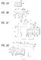
- FIGS. 4A to 4C show modifications of the first embodiment, in which the direction of conveyance is changed.
- FIG. 4A shows one of the modifications in which the direction of conveyance B is opposite to that in the case of FIGS. 3A to 3D.
- the marking operation is started when the mark reference point O 3 reaches the irradiation start point S T , and the marking operation is ended when the mark reference point O 1 reaches the irradiation end point E.
- FIG. 4B shows another modification in which the direction of conveyance B forms 90° with that in the case of FIGS. 3A to 3D.
- the marking operation is started when the mark reference point O 1 reaches the irradiation start point S T , and the marking operation is ended when the mark reference point O 4 reaches the irradiation end point E.
- FIG. 4C shows another modification in which the direction of conveyance B is opposite to that in the modification shown in FIG. 4B.
- the marking operation is started when the mark reference point O 4 reaches the irradiation start point S T , and the marking operation is ended when the mark reference point O 1 reaches the irradiation end point E.
- the target area A T is provided in the maximum area A M .
- the target area A T may be eliminated; that is, only the maximum area A M may be provided and stored.
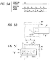
- FIGS. 5A to 5C show a second embodiment of the invention.
- the conveying speed v is not uniform, or unknown.
- a position sensor 30 is provided as indicated by the broken line in FIGS. 5B and 5C. The position sensor 30 outputs a position pulse signal as shown in FIG. 5A whenever the conveying surface moves a predetermined distance, irrespective of the conveying speed v of the conveying device 6.
- the marking operation may last longer as much as the difference (b - d) than in the case of FIGS. 3A to 3D.
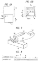
- FIGS. 6A to 6B show one modification of the second embodiment, in which the direction of conveyance B is perpendicular to that in the second embodiment shown in FIGS. 5A to 5C.
- the marking operation is started when the mark reference point O 1 shown in FIG. 6A reaches the irradiation start point S T , and it is ended when the mark reference point O 7 shown in FIG. 6B reaches the irradiation end point E.
- the workpiece W (FIG. 1) is moved during the marking operation; however, the technical concept of the invention may be applied to the case where the workpiece W is held at rest.
- the conveying device 6 is able to intermittently convey the workpiece W, and after the workpiece W enters the maximum area A M , the conveying device 6 is stopped for a predetermined time, and the marking operation is carried out during the predetermined time; the scanning speeds may be set most suitable for the predetermined time for which the conveying device is held stopped.
- the target time T is set shorter than the time for which the workpiece W is held stopped.
- the technical concept of the invention may be applied to the case where workpieces W are automatically supplied to the laser marking device one at a time, and the scanning speeds should be set most suitable for the workpiece supply cycle.
- the target time T should be set equal to or shorter than the time which is allowed for the marking operation.
- a mark of has a plurality of mark reference points O 1 through O N as shown in FIGS. 3A to 3D; however, the invention is not limited thereto or thereby. That is, the technical concept of the invention is applicable to the case where a mark has only one mark reference point (O 1 ).
- the laser marking device is modified so that the marking operation is accomplished within the period of time which elapses from the time instant the mark reference point O 1 shown in FIG. 3C reaches the irradiation start point S T until it reaches the irradiation end point E.
- the amount of movement L is (a + b) in the first embodiment shown in FIGS. 3A to 3D, and it is (a + d) in the second embodiment shown in FiGS. 5A to 5C.
- the amount of movement L may be set to a suitable valve in the following range: (a + d) ⁇ L ⁇ (a + b).
- objects 181 are conveyed in one direction by a conveying stand 141.
- the conveying speed is for instance 40 m/min.
- the conveying stand 141 is provided with a position detector 142 made up of a rotary encoder or the like, to measure the amount of movement (distance) of an object 181.
- the position detector 142 outputs encoder pulses P according to the movement of the conveying stand as shown in the part (a) of FIG. 8.
- a marking head 180 including a CO 2 laser and an optical scanning system is set above the conveying stand 141 with the aid of a supporting arm 143.
- the marking head 180 has a beam outlet directed towards the object 181.
- the marking head 180 is connected to a controller 140 (described later), to control the on/off operation of the CO 2 laser and the beam deflecting operation of the optical scanning system.
- the laser scanning speed of the marking head 180 is for instance 3000 mm/sec.
- the position detection signal outputted by the position detector 142 is applied to the controller 140, so as to allow the latter to control the optical scanning system.
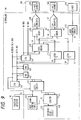
- FIG. 9 shows the internal arrangement of the controller 140.
- a CPU 101 has an address bus line and a data bus line which ore connected to a ROM 102 and a RAM 103, and to a GDC (graphic display controller) 104 made up of a graphic LSI.
- the GDC 104 may be one " ⁇ PC72123" manufactured by NEC Company.
- the graphic data include various line elements (straight lines, ellipses, etc.), the coordinates of the start and end points of each of the line elements, and the coordinates of the center of and the lengths of the major and minor axes of each of the ellipses.
- the graphic data further include laser on/off basic data for turning on and off the laser respectively at the start and end of each of the line elements.
- the CPU 101 executes a computer program stored in the ROM 102, to form a graphic-form describing command including the above-described graphic data, and applies it to the GDC 104.
- the GDC 104 calculates the coordinate data of a number of locus points between the start and end point of the line element according to the command, and calculates laser on/off data corresponding to the locus points according to the aforementioned laser on/off basic data.
- the data outputting speed of the GDC 104 is such that, for instance in the case of describing one straight line, one coordinate data outputting time is 0.2 ⁇ s. That is, the data outputting speed of the GDC 104 is much higher than the operating speed (5.0 ⁇ s or more per coordinate point) of an X-axis scanner 108 or a Y-axis scanner 109 (described later).
- the coordinate data and the laser on/off data provided by the GDC 104 are applied respectively through a graphic address bus line GA and a graphic data bus line GD to an FIFO (first-in first-out) memory 105.
- the FIFO memory 105 is able to store data on sixtyfour (64) locus points for instance. Those data are sequentially stored in addresses, respectively, and are read from them at a constant rate.
- X-axis coordinate data Ax are applied to a first input terminal of an X-adder 150
- Y-axis coordinate data Ay are applied to a first input terminal of a Y-adder 151.
- the laser on/off data D read from the FIFO memory 105 is applied to a laser control circuit 113, where it is utilized to form a control signal for on-off control of a CO 2 laser 114.
- the encoder pulse P provided by the position detector 142 is applied to the timing signal input terminals of a latch circuit 120 and of a reset signal forming circuit 144.
- the latch circuit 120 has a data input port which is connected through a counter 121 to a reference clock circuit 122.
- the counter 121 receives a reset signal RE from the reset signal forming circuit 144.
- the counter 121 while being reset by the reset signal RE every period t of the encoder pulse P, counts the clock pulses CLK which the reference clock circuit 122 outputs for the period t as shown in the part (b) of FIG. 8, and applies the count value to the latch circuit 120.
- the CPU 101 applies a data read instruction through the address bus line to the latch circuit 120, the data latched in the latch circuit 120 is read into the CPU 101 through the data bus line.
- the CPU 101 calculates position correcting data Bx in the direction of X-axis (hereinafter referred to as "X-direction position correcting data Bx", when applicable) and position correcting data By in the direction of Y-axis (hereinafter referred to as “Y-axis position correcting data By”, when applicable) as described later.
- the data bus line of the CPU 101 is connected to a latch-X 110 adapted to latch the X-axis position correcting data Bx and to a latch-Y 111 adapted to latch the Y-axis position correcting data By.
- the output terminals of those latches 110 and 111 are connected to second input terminals of the X-adder 150 and of the Y-adder 151, respectively.
- the output terminals of the X-adder 150 and the Y-adder 151 are connected through D/A (digital-to-analog) converters 106 and 107 to an X-axis scanner 108 and a Y-axis scanner 109, respectively.
- D/A digital-to-analog
- the position detector 142 outputs an encoder pulse P as shown in the part (a) of FIG. 8 according to the movement of the conveying stand 141.
- the encoder pulse P is applied to the reset signal forming circuit 144, so that the counter 121 is reset.
- the counter 121 starts counting the clock pulses CLK provided by the reference clock circuit 122.
- the next encoder pulse P when produced, is applied to the latch circuit 120, so that the count value of the counter 121 is latched by the latch circuit 120.
- the CPU 101 makes access to the latch circuit 120 to fetch the count value. And the CPU 101 converts the count value into time to obtain the period t .
- the CPU 101 further operates as follows: That is, the CPU 101 calculates the X-axis position correcting data Bx and the Y-axis position correcting data By.
- a graphic form can be described on the object 181 which is moving, by the following method: That is, for every time g , the position correcting data Bx for increasing the coordinate data as much as one (7) dot is calculated, and the X-axis scanner 108 is operated according to the corrected coordinate data which is obtained by adding the position correcting data to the original coordinate data.
- the position correcting data Bx is transmitted from the latch-x 110 to the X-adder 150 with the timing that the coordinate data Ax is applied from the FIFO memory 105 to the X-adder 150.
- the coordinate data Ax is added to the position correcting data Bx, to form corrected coordinate data Ax' which is applied through the D/A converter 106 to the X-axis scanner 108.
- the position correcting data By is calculated, and the Y-axis scanner 109 is operated according to corrected coordinate data which is obtained by adding the position correcting data By to the original coordinate data. That is, after the position correcting data Bx provided by the CPU 101 is latched by the latch-Y 111, the position correcting data By is transmitted from the latch-Y 111 to the Y-adder 151 with the timing that the coordinate data Ay is applied from the FIFO memory 105 to the Y-adder 151. As a result, the Y-adder 151 operates to add the coordinate data Ay to the position correcting data By, to form corrected coordinate data Ay' which is applied through the D/A converter 107 to the Y-axis scanner 108.
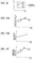
- the coordinate data Ax changes in the direction of X-axis as shown in FIG. 11A.
- the position of the object 181 changes as shown in FIG. 11B.
- the aforementioned coordinate data Ax' is calculated.
- the object is scanned in the direction of X-axis according to the data Ax' thus calculated.
- the position detector 142 is provided for the conveying stand 141 to detect the change in position of the object 181.
- the position correcting data is formed according to the time g , and then the corrected coordinate data is calculated.
- the scanning speed is so determined that the marking operation is started when the mark reference point reaches the irradiation start point located upstream as viewed in the direction of movement of the workpiece, and it is ended when the mark reference point reach the irradiation end point.
- the marking operation can be achieved while the workpiece moves a relatively long distance.
- the scanning speed can be decreased when compared with the case where the scanning speed is fixedly set to a high value; that is, the scanning speed can be set to a suitable value. That is, with a low laser output, a mark can be described on the workpiece within a given period of time which is high in picture quality.
- the scan type laser marking device of the invention With the scan type laser marking device of the invention, the time is measured which is required for the marking operation carried out with the reference scanning speed, and the individual scanning speeds are obtained according to the time thus measured, the reference scanning speed, and the target time. Hence, with the device, a mark high in picture quality can be described on the workpiece by using suitable individual scanning speeds, which can be readily obtained.
- the target area is provided inside the maximum area.
- the marking operation is normally carried out in the target area so that a mark high in picture quality is formed on the workpiece. And even in the case where a marking operation is forced to be performed outside the target area because the workpiece conveying speed is not uniform, the mark can be described on the workpiece.
Description
Claims (7)
- A scan type laser marking device which scans the surface of an object (W) conveyed in a predetermined area (AT,AM) and applies a laser beam (LB) to the surface of the object (W) to form a mark (M) on the surface of the object (W), said scan type laser marking device comprising:an area storing section (23,22) for storing said predetermined area (AT,AM);a start point coordinate storing section (24) for storing coordinates of an irradiation start point (ST) in said predetermined area (AT,AM), the irradiation start point (ST) being located on the upstream side relating to the direction of conveyance of the object (W);an end point coordinate storing section (25) for storing coordinates of an irradiation end point (E) in said predetermined area, the irradiation end point (E) being located on the downstream side relating to the direction of conveyance of the object (W);a mark reference point section (21) for storing the coordinates of a reference point (O1,O2,O3) on the mark (M);and speed setting means (13) for setting scanning speeds so that a marking operation is started when the mark reference point (O1) reaches the irradiation start point (ST), and is ended when the mark reference point (O3) reaches the irradiation end point (E).
- A scan type laser marking device according to claim 1, wherein a conveyance distance of the object (W) during the marking operation satisfies following equations:where L is the conveyance distance of the object (W); a is a length from a front line of the frontmost mark to a rear line of the rearmost mark; c is a length of said predetermined area relating to the direction of conveyance of the object (W); and d is a length of the mark.
- A scan type laser marking device which scans the surface of an object (W) conveyed in a predetermined area and applies a laser beam (LB) on the surface of the object (W) to form a mark (M) on the surface of the object (W), said scan type laser marking device comprising:measuring means (14) for measuring a time (T0) which is required for performing a marking operation with a reference scanning speed (S0); andscanning speed calculating means (13a) for utilizing the time thus measured, a marking target time (T) which is the time required for the object (W) to move across the predetermined area, and said reference scanning speed (S0) to calculate individual scanning speeds (S) which are to be actually used.
- A scan type laser marking device according to claim 3, wherein the target time is set as a value that the object (W) is conveyed a distance L, and wherein L satisfies following equations:where a is a length from a front line of the frontmost mark to a rear line of the rearmost mark; c is a length of said predetermined area relating to the direction of conveyance of the object (W); and d is a length of the mark.
- A scan type laser marking device which scans the surface of an object (W) conveyed in a predetermined area and applies a laser beam (LB) on the surface of the object (W) to form a mark (M) on the surface of the object (W), said scanning type laser marking device comprising:a maximum area storing section (22) for storing a maximum area (AM) where a marking operation is allowed;a target area storing section (23) for storing a target area (AT) smaller than the maximum area; andspeed setting means (13) for setting a scanning speed (S) so that a marking operation is accomplished within the target area (AT).
- A scan type laser marking device according to claim 5, wherein a conveyance distance of the object (W) during the marking operation satisfies following equations:where L is the conveyance distance of the object (W); a is a length from a front line of the frontmost mark to a rear line of the rearmost mark; c is a length of the target area relating to the direction of conveyance of the object (W); and d is a length of the mark.
- A scan type laser marking device which, while applying a laser beam to the surface of a moving object, scans the laser beam two-dimensionally to describe graphic forms having a plurality of dots, said laser marking device comprising:a laser source emitting the laser beam;an optical scanning system for deflecting two-dimensionally the laser beam emitted by said laser source;a control system for controlling the operation of said optical scanning system; andmeans for inputting displacement data on a displacement of the object,
said control system including:wherein the coordinate date corrected by said coordinate correcting means is applied to said optical scanning system.coordinate producing means for producing coordinate data on the dots forming the graphic form; andcoordinate correcting means for correcting, according to the displacement data, the coordinate data as much as the displacement of the object in the direction of displacement thereof,
Priority Applications (1)
| Application Number | Priority Date | Filing Date | Title |
|---|---|---|---|
| EP98114830A EP0883277A3 (en) | 1993-12-03 | 1994-12-02 | Scan type laser marking device |
Applications Claiming Priority (6)
| Application Number | Priority Date | Filing Date | Title |
|---|---|---|---|
| JP1993064800U JP2565096Y2 (en) | 1993-12-03 | 1993-12-03 | Laser marking device |
| JP64800/93U | 1993-12-03 | ||
| JP6480093U | 1993-12-03 | ||
| JP34081393A JP3311452B2 (en) | 1993-12-08 | 1993-12-08 | Scanning laser mark device |
| JP34081393 | 1993-12-08 | ||
| JP340813/93 | 1993-12-08 |
Related Child Applications (1)
| Application Number | Title | Priority Date | Filing Date |
|---|---|---|---|
| EP98114830.7 Division-Into | 1998-08-06 |
Publications (3)
| Publication Number | Publication Date |
|---|---|
| EP0661867A2 EP0661867A2 (en) | 1995-07-05 |
| EP0661867A3 EP0661867A3 (en) | 1996-01-17 |
| EP0661867B1 true EP0661867B1 (en) | 2000-06-07 |
Family
ID=26405900
Family Applications (2)
| Application Number | Title | Priority Date | Filing Date |
|---|---|---|---|
| EP94119056A Expired - Lifetime EP0661867B1 (en) | 1993-12-03 | 1994-12-02 | Scan type laser marking device |
| EP98114830A Withdrawn EP0883277A3 (en) | 1993-12-03 | 1994-12-02 | Scan type laser marking device |
Family Applications After (1)
| Application Number | Title | Priority Date | Filing Date |
|---|---|---|---|
| EP98114830A Withdrawn EP0883277A3 (en) | 1993-12-03 | 1994-12-02 | Scan type laser marking device |
Country Status (5)
| Country | Link |
|---|---|
| US (2) | US5734412A (en) |
| EP (2) | EP0661867B1 (en) |
| KR (1) | KR100302806B1 (en) |
| DE (1) | DE69424852T2 (en) |
| TW (1) | TW267961B (en) |
Families Citing this family (42)
| Publication number | Priority date | Publication date | Assignee | Title |
|---|---|---|---|---|
| US5936710A (en) * | 1996-01-05 | 1999-08-10 | Canon Kabushiki Kaisha | Scanning type exposure apparatus, position control apparatus, and method therefor |
| DE19727957A1 (en) * | 1996-07-02 | 1998-01-08 | Miyachi Technos Kk | Scanning laser marker |
| DE19711243A1 (en) * | 1997-03-18 | 1998-10-01 | Wolfgang Deutscher | Laser printing arrangement |
| US6160568A (en) * | 1997-05-27 | 2000-12-12 | Sdl, Inc. | Laser marking system and method of energy control |
| US6075223A (en) * | 1997-09-08 | 2000-06-13 | Thermark, Llc | High contrast surface marking |
| US6852948B1 (en) | 1997-09-08 | 2005-02-08 | Thermark, Llc | High contrast surface marking using irradiation of electrostatically applied marking materials |
| US6154628A (en) * | 1997-09-29 | 2000-11-28 | Matsushita Electric Industrial Co., Ltd. | Image forming device with misregistration correction achieved by photo-conductor speed controlled variation of latent image tilt |
| DE19816992A1 (en) * | 1998-04-17 | 1999-11-04 | Daimler Chrysler Ag | Method for marking at least one point on an object |
| US6275250B1 (en) | 1998-05-26 | 2001-08-14 | Sdl, Inc. | Fiber gain medium marking system pumped or seeded by a modulated laser diode source and method of energy control |
| US6331691B1 (en) * | 1999-09-20 | 2001-12-18 | Automated Laser Corporation | Precision guiding apparatus for laser marking system |
| US6469729B1 (en) | 1999-10-15 | 2002-10-22 | Videojet Technologies Inc. | Laser marking device and method for marking arcuate surfaces |
| JP3429463B2 (en) * | 1999-10-22 | 2003-07-22 | サンクス株式会社 | Laser marker |
| US7050653B2 (en) * | 2000-04-05 | 2006-05-23 | Anoto Ab | Identification of virtual raster pattern |
| US6791592B2 (en) * | 2000-04-18 | 2004-09-14 | Laserink | Printing a code on a product |
| DE10042537B4 (en) * | 2000-08-30 | 2014-10-16 | Volkswagen Ag | Method for checking a surface for defective areas |
| US6776109B2 (en) | 2000-12-13 | 2004-08-17 | Columbia Insurance Company | Bow and skew control system and method |
| DE10146820B4 (en) * | 2001-09-19 | 2005-02-24 | Tampoprint Gmbh | Decorating device and method for decorating surfaces |
| US6646671B1 (en) * | 2001-12-27 | 2003-11-11 | Advanced Micro Devices, Inc. | Method and system for synchronizing lead scanners and laser marker modules |
| US7011880B2 (en) * | 2002-07-03 | 2006-03-14 | The Gates Corporation | Belt and method of marking |
| US7238396B2 (en) * | 2002-08-02 | 2007-07-03 | Rieck Albert S | Methods for vitrescent marking |
| US7951409B2 (en) | 2003-01-15 | 2011-05-31 | Newmarket Impressions, Llc | Method and apparatus for marking an egg with an advertisement, a freshness date and a traceability code |
| US20050088510A1 (en) * | 2003-10-24 | 2005-04-28 | Shlomo Assa | Low angle optics and reversed optics |
| US6958762B2 (en) * | 2003-12-09 | 2005-10-25 | Markem Corporation | Filling an area of an image marked on a material with a laser |
| US7046267B2 (en) * | 2003-12-19 | 2006-05-16 | Markem Corporation | Striping and clipping correction |
| DE102004023021B4 (en) * | 2004-05-06 | 2009-11-12 | Pro-Beam Ag & Co. Kgaa | Method for ablative processing of surface areas |
| DE102005002670B4 (en) * | 2005-01-14 | 2009-07-30 | Fraunhofer-Gesellschaft zur Förderung der angewandten Forschung e.V. | Method for machining workpieces by means of laser radiation |
| GB0508360D0 (en) * | 2005-04-25 | 2005-06-01 | Sherwood Technology Ltd | Printing system |
| FR2907370B1 (en) * | 2006-10-18 | 2017-11-17 | Tiama | METHOD AND INSTALLATION FOR HOT MARKING OF TRANSLUCENT OR TRANSPARENT OBJECTS |
| US8084712B2 (en) | 2007-03-16 | 2011-12-27 | TEN Medias LLC | Method and apparatus for laser marking objects |
| JP2009142865A (en) * | 2007-12-14 | 2009-07-02 | Keyence Corp | Laser processing apparatus, laser processing method, and method for making settings for laser processing apparatus |
| JP2009142864A (en) * | 2007-12-14 | 2009-07-02 | Keyence Corp | Laser processing apparatus, method for making settings for laser processing apparatus, program for making settings for laser processing apparatus, and computer-readable recording medium |
| US7529636B1 (en) | 2008-05-19 | 2009-05-05 | International Business Machines Corporation | Enabling safe use of high power laser for laser marking in a free space environment |
| ES2380480B8 (en) * | 2010-04-21 | 2013-11-14 | Macsa Id, S.A. | DEVICE AND PROCEDURE TO MARK THROUGH LASER A MOVING OBJECT. |
| GB201008334D0 (en) | 2010-05-19 | 2010-07-07 | Materials Solutions | Laser scan speed calibration |
| CN103639591A (en) * | 2013-11-21 | 2014-03-19 | 吕武全 | Laser marking method |
| US9744559B2 (en) | 2014-05-27 | 2017-08-29 | Paul W Harrison | High contrast surface marking using nanoparticle materials |
| KR102540188B1 (en) | 2015-06-22 | 2023-06-07 | 일렉트로 싸이언티픽 인더스트리이즈 인코포레이티드 | Multi-axis machine tools and how to control them |
| JP6829063B2 (en) | 2016-12-08 | 2021-02-10 | パナソニック デバイスSunx株式会社 | Laser processing equipment |
| KR102203579B1 (en) | 2017-12-31 | 2021-01-15 | 주식회사 에이티앤씨 | A laser marking apparatus using tray |
| US10583668B2 (en) | 2018-08-07 | 2020-03-10 | Markem-Imaje Corporation | Symbol grouping and striping for wide field matrix laser marking |
| KR20200082877A (en) | 2018-12-31 | 2020-07-08 | 주식회사 에이티앤씨 | A laser marking method using tray |
| EP3711966B1 (en) * | 2019-03-20 | 2021-12-15 | Alltec Angewandte Laserlicht Technologie GmbH | Method for applying a marking on an object and marking apparatus |
Family Cites Families (11)
| Publication number | Priority date | Publication date | Assignee | Title |
|---|---|---|---|---|
| JPS5511824A (en) * | 1978-07-12 | 1980-01-28 | Hitachi Ltd | Printing speed synchronizing device of ink jet recording device |
| JPS5526563A (en) * | 1978-08-16 | 1980-02-26 | Fuji Photo Film Co Ltd | Light beam scanner |
| JPS5853444A (en) * | 1981-09-25 | 1983-03-30 | Nec Corp | Laser marking device |
| JPS5945091A (en) * | 1982-09-07 | 1984-03-13 | Toshiba Corp | Laser printing and working device |
| US4707709A (en) * | 1986-01-17 | 1987-11-17 | Eastman Kodak Company | Image recording apparatus in which exposure levels are a function of image contents |
| JPS62187977A (en) * | 1986-02-13 | 1987-08-17 | Dainippon Screen Mfg Co Ltd | Image data processor |
| JPH01120349A (en) * | 1987-11-04 | 1989-05-12 | Nec Corp | Photoplotter |
| JPH01266749A (en) * | 1988-04-18 | 1989-10-24 | Nec Corp | Continuous laser mark device |
| JPH03113410A (en) * | 1989-09-27 | 1991-05-14 | Canon Inc | Laser scanning device |
| JP2829161B2 (en) * | 1991-09-18 | 1998-11-25 | 三菱電機株式会社 | Ignition timing control device for internal combustion engine |
| JPH05169286A (en) * | 1991-12-25 | 1993-07-09 | Fuji Electric Co Ltd | Laser beam scale marking device |
-
1994
- 1994-12-02 DE DE69424852T patent/DE69424852T2/en not_active Expired - Lifetime
- 1994-12-02 EP EP94119056A patent/EP0661867B1/en not_active Expired - Lifetime
- 1994-12-02 TW TW083111254A patent/TW267961B/zh not_active IP Right Cessation
- 1994-12-02 KR KR1019940032542A patent/KR100302806B1/en not_active IP Right Cessation
- 1994-12-02 EP EP98114830A patent/EP0883277A3/en not_active Withdrawn
- 1994-12-05 US US08/341,210 patent/US5734412A/en not_active Expired - Lifetime
-
1997
- 1997-10-28 US US08/959,164 patent/US6061081A/en not_active Expired - Lifetime
Also Published As
| Publication number | Publication date |
|---|---|
| US6061081A (en) | 2000-05-09 |
| EP0661867A2 (en) | 1995-07-05 |
| US5734412A (en) | 1998-03-31 |
| DE69424852T2 (en) | 2000-11-09 |
| DE69424852D1 (en) | 2000-07-13 |
| KR950017055A (en) | 1995-07-20 |
| EP0883277A3 (en) | 1999-08-18 |
| TW267961B (en) | 1996-01-11 |
| EP0661867A3 (en) | 1996-01-17 |
| KR100302806B1 (en) | 2001-11-22 |
| EP0883277A2 (en) | 1998-12-09 |
Similar Documents
| Publication | Publication Date | Title |
|---|---|---|
| EP0661867B1 (en) | Scan type laser marking device | |
| US20020075180A1 (en) | Autonomous moving apparatus having obstacle avoidance funtion | |
| EP0532169A1 (en) | Optical Inspection Probe | |
| EP0606083B1 (en) | Exterior view inspecting apparatus for circuit board | |
| US5481096A (en) | Bar code reader and method for its operation | |
| JP2003136260A (en) | Laser marking device | |
| JP5081557B2 (en) | Laser processing equipment | |
| KR100316827B1 (en) | Laser Mark Device | |
| JP2005211979A (en) | Laser marking apparatus and laser marking method | |
| JP2568388B2 (en) | Shape measuring device | |
| US6752318B2 (en) | Optical symbol reading device | |
| JP2004507171A (en) | Electronic correction method of image distortion in laser scanning device | |
| US6423931B1 (en) | Method of controlling the movement of a laser engraving head | |
| JP7061617B2 (en) | Scanning type optical output device and its control method | |
| JPH0733475U (en) | Laser marking device | |
| CN100540311C (en) | Method of printing | |
| JP3846621B2 (en) | Marking method and coating surface inspection device with marking function | |
| JP2001010142A (en) | Marking apparatus | |
| JP2007007699A (en) | Laser marking device | |
| JP2002019071A (en) | Printing solder inspecting system and solder printer with inspecting function | |
| KR100479580B1 (en) | Laser marking device for high speed moving workpiece | |
| JP2020091157A (en) | Optical distance measuring device and transfer system | |
| JPH1183434A (en) | Detection system using light projection type three-dimensional sensor and detection method | |
| JP3311452B2 (en) | Scanning laser mark device | |
| JP2002040352A (en) | Scanner and three-dimensional measuring device |
Legal Events
| Date | Code | Title | Description |
|---|---|---|---|
| PUAI | Public reference made under article 153(3) epc to a published international application that has entered the european phase |
Free format text: ORIGINAL CODE: 0009012 |
|
| AK | Designated contracting states |
Kind code of ref document: A2 Designated state(s): DE FR GB |
|
| PUAL | Search report despatched |
Free format text: ORIGINAL CODE: 0009013 |
|
| AK | Designated contracting states |
Kind code of ref document: A3 Designated state(s): DE FR GB |
|
| 17P | Request for examination filed |
Effective date: 19960715 |
|
| 17Q | First examination report despatched |
Effective date: 19980327 |
|
| GRAG | Despatch of communication of intention to grant |
Free format text: ORIGINAL CODE: EPIDOS AGRA |
|
| RIC1 | Information provided on ipc code assigned before grant |
Free format text: 6H 04N 1/047 A, 6H 04N 1/04 B, 6B 23K 26/00 B |
|
| GRAG | Despatch of communication of intention to grant |
Free format text: ORIGINAL CODE: EPIDOS AGRA |
|
| GRAG | Despatch of communication of intention to grant |
Free format text: ORIGINAL CODE: EPIDOS AGRA |
|
| GRAH | Despatch of communication of intention to grant a patent |
Free format text: ORIGINAL CODE: EPIDOS IGRA |
|
| GRAH | Despatch of communication of intention to grant a patent |
Free format text: ORIGINAL CODE: EPIDOS IGRA |
|
| GRAA | (expected) grant |
Free format text: ORIGINAL CODE: 0009210 |
|
| AK | Designated contracting states |
Kind code of ref document: B1 Designated state(s): DE FR GB |
|
| REF | Corresponds to: |
Ref document number: 69424852 Country of ref document: DE Date of ref document: 20000713 |
|
| ET | Fr: translation filed | ||
| PLBE | No opposition filed within time limit |
Free format text: ORIGINAL CODE: 0009261 |
|
| STAA | Information on the status of an ep patent application or granted ep patent |
Free format text: STATUS: NO OPPOSITION FILED WITHIN TIME LIMIT |
|
| 26N | No opposition filed | ||
| REG | Reference to a national code |
Ref country code: GB Ref legal event code: IF02 |
|
| PGFP | Annual fee paid to national office [announced via postgrant information from national office to epo] |
Ref country code: GB Payment date: 20091202 Year of fee payment: 16 Ref country code: FR Payment date: 20091221 Year of fee payment: 16 |
|
| PGFP | Annual fee paid to national office [announced via postgrant information from national office to epo] |
Ref country code: DE Payment date: 20101124 Year of fee payment: 17 |
|
| GBPC | Gb: european patent ceased through non-payment of renewal fee |
Effective date: 20101202 |
|
| REG | Reference to a national code |
Ref country code: FR Ref legal event code: ST Effective date: 20110831 |
|
| PG25 | Lapsed in a contracting state [announced via postgrant information from national office to epo] |
Ref country code: FR Free format text: LAPSE BECAUSE OF NON-PAYMENT OF DUE FEES Effective date: 20110103 |
|
| PG25 | Lapsed in a contracting state [announced via postgrant information from national office to epo] |
Ref country code: GB Free format text: LAPSE BECAUSE OF NON-PAYMENT OF DUE FEES Effective date: 20101202 |
|
| REG | Reference to a national code |
Ref country code: DE Ref legal event code: R119 Ref document number: 69424852 Country of ref document: DE Effective date: 20120703 |
|
| PG25 | Lapsed in a contracting state [announced via postgrant information from national office to epo] |
Ref country code: DE Free format text: LAPSE BECAUSE OF NON-PAYMENT OF DUE FEES Effective date: 20120703 |