EP0660262A2 - Transparent hologram seal - Google Patents
Transparent hologram seal Download PDFInfo
- Publication number
- EP0660262A2 EP0660262A2 EP94120761A EP94120761A EP0660262A2 EP 0660262 A2 EP0660262 A2 EP 0660262A2 EP 94120761 A EP94120761 A EP 94120761A EP 94120761 A EP94120761 A EP 94120761A EP 0660262 A2 EP0660262 A2 EP 0660262A2
- Authority
- EP
- European Patent Office
- Prior art keywords
- layer
- base member
- transparent
- refractive index
- laminated body
- Prior art date
- Legal status (The legal status is an assumption and is not a legal conclusion. Google has not performed a legal analysis and makes no representation as to the accuracy of the status listed.)
- Granted
Links
- 239000010410 layer Substances 0.000 claims abstract description 702
- 239000012790 adhesive layer Substances 0.000 claims abstract description 36
- GWEVSGVZZGPLCZ-UHFFFAOYSA-N Titan oxide Chemical compound O=[Ti]=O GWEVSGVZZGPLCZ-UHFFFAOYSA-N 0.000 claims description 62
- VYPSYNLAJGMNEJ-UHFFFAOYSA-N Silicium dioxide Chemical compound O=[Si]=O VYPSYNLAJGMNEJ-UHFFFAOYSA-N 0.000 claims description 61
- 239000000377 silicon dioxide Substances 0.000 claims description 30
- 235000012239 silicon dioxide Nutrition 0.000 claims description 30
- 239000004408 titanium dioxide Substances 0.000 claims description 25
- 229910001635 magnesium fluoride Inorganic materials 0.000 claims description 24
- 229910010293 ceramic material Inorganic materials 0.000 claims description 22
- 239000010409 thin film Substances 0.000 claims description 21
- ORUIBWPALBXDOA-UHFFFAOYSA-L magnesium fluoride Chemical compound [F-].[F-].[Mg+2] ORUIBWPALBXDOA-UHFFFAOYSA-L 0.000 claims description 20
- 229910052984 zinc sulfide Inorganic materials 0.000 claims description 19
- 239000005083 Zinc sulfide Substances 0.000 claims description 16
- DRDVZXDWVBGGMH-UHFFFAOYSA-N zinc;sulfide Chemical compound [S-2].[Zn+2] DRDVZXDWVBGGMH-UHFFFAOYSA-N 0.000 claims description 16
- MCMNRKCIXSYSNV-UHFFFAOYSA-N ZrO2 Inorganic materials O=[Zr]=O MCMNRKCIXSYSNV-UHFFFAOYSA-N 0.000 claims description 14
- OKTJSMMVPCPJKN-UHFFFAOYSA-N Carbon Chemical compound [C] OKTJSMMVPCPJKN-UHFFFAOYSA-N 0.000 claims description 12
- 229910052799 carbon Inorganic materials 0.000 claims description 12
- RVTZCBVAJQQJTK-UHFFFAOYSA-N oxygen(2-);zirconium(4+) Chemical compound [O-2].[O-2].[Zr+4] RVTZCBVAJQQJTK-UHFFFAOYSA-N 0.000 claims description 11
- PXHVJJICTQNCMI-UHFFFAOYSA-N Nickel Chemical compound [Ni] PXHVJJICTQNCMI-UHFFFAOYSA-N 0.000 claims description 10
- 229910052782 aluminium Inorganic materials 0.000 claims description 9
- XAGFODPZIPBFFR-UHFFFAOYSA-N aluminium Chemical compound [Al] XAGFODPZIPBFFR-UHFFFAOYSA-N 0.000 claims description 9
- HBMJWWWQQXIZIP-UHFFFAOYSA-N silicon carbide Chemical compound [Si+]#[C-] HBMJWWWQQXIZIP-UHFFFAOYSA-N 0.000 claims description 6
- 229910010271 silicon carbide Inorganic materials 0.000 claims description 6
- VYZAMTAEIAYCRO-UHFFFAOYSA-N Chromium Chemical compound [Cr] VYZAMTAEIAYCRO-UHFFFAOYSA-N 0.000 claims description 5
- PCHJSUWPFVWCPO-UHFFFAOYSA-N gold Chemical compound [Au] PCHJSUWPFVWCPO-UHFFFAOYSA-N 0.000 claims description 5
- 229910052737 gold Inorganic materials 0.000 claims description 5
- 239000010931 gold Substances 0.000 claims description 5
- 239000000395 magnesium oxide Substances 0.000 claims description 5
- CPLXHLVBOLITMK-UHFFFAOYSA-N magnesium oxide Inorganic materials [Mg]=O CPLXHLVBOLITMK-UHFFFAOYSA-N 0.000 claims description 5
- AXZKOIWUVFPNLO-UHFFFAOYSA-N magnesium;oxygen(2-) Chemical compound [O-2].[Mg+2] AXZKOIWUVFPNLO-UHFFFAOYSA-N 0.000 claims description 5
- 229910052759 nickel Inorganic materials 0.000 claims description 5
- XLOMVQKBTHCTTD-UHFFFAOYSA-N Zinc monoxide Chemical compound [Zn]=O XLOMVQKBTHCTTD-UHFFFAOYSA-N 0.000 claims description 4
- 150000004767 nitrides Chemical class 0.000 claims description 4
- CETPSERCERDGAM-UHFFFAOYSA-N ceric oxide Chemical compound O=[Ce]=O CETPSERCERDGAM-UHFFFAOYSA-N 0.000 claims description 3
- QCCDYNYSHILRDG-UHFFFAOYSA-K cerium(3+);trifluoride Chemical compound [F-].[F-].[F-].[Ce+3] QCCDYNYSHILRDG-UHFFFAOYSA-K 0.000 claims description 3
- 229910000422 cerium(IV) oxide Inorganic materials 0.000 claims description 3
- TWNQGVIAIRXVLR-UHFFFAOYSA-N oxo(oxoalumanyloxy)alumane Chemical compound O=[Al]O[Al]=O TWNQGVIAIRXVLR-UHFFFAOYSA-N 0.000 claims description 3
- IRPGOXJVTQTAAN-UHFFFAOYSA-N 2,2,3,3,3-pentafluoropropanal Chemical compound FC(F)(F)C(F)(F)C=O IRPGOXJVTQTAAN-UHFFFAOYSA-N 0.000 claims description 2
- KLZUFWVZNOTSEM-UHFFFAOYSA-K Aluminum fluoride Inorganic materials F[Al](F)F KLZUFWVZNOTSEM-UHFFFAOYSA-K 0.000 claims description 2
- 229910052580 B4C Inorganic materials 0.000 claims description 2
- INAHAJYZKVIDIZ-UHFFFAOYSA-N boron carbide Chemical compound B12B3B4C32B41 INAHAJYZKVIDIZ-UHFFFAOYSA-N 0.000 claims description 2
- WUKWITHWXAAZEY-UHFFFAOYSA-L calcium difluoride Chemical compound [F-].[F-].[Ca+2] WUKWITHWXAAZEY-UHFFFAOYSA-L 0.000 claims description 2
- 229910001634 calcium fluoride Inorganic materials 0.000 claims description 2
- 229910003437 indium oxide Inorganic materials 0.000 claims description 2
- PJXISJQVUVHSOJ-UHFFFAOYSA-N indium(iii) oxide Chemical compound [O-2].[O-2].[O-2].[In+3].[In+3] PJXISJQVUVHSOJ-UHFFFAOYSA-N 0.000 claims description 2
- BPUBBGLMJRNUCC-UHFFFAOYSA-N oxygen(2-);tantalum(5+) Chemical compound [O-2].[O-2].[O-2].[O-2].[O-2].[Ta+5].[Ta+5] BPUBBGLMJRNUCC-UHFFFAOYSA-N 0.000 claims description 2
- 229910001936 tantalum oxide Inorganic materials 0.000 claims description 2
- 239000011787 zinc oxide Substances 0.000 claims description 2
- 239000000919 ceramic Substances 0.000 abstract description 13
- 238000010030 laminating Methods 0.000 abstract description 11
- 239000010408 film Substances 0.000 description 77
- 238000002474 experimental method Methods 0.000 description 67
- 229920005989 resin Polymers 0.000 description 51
- 239000011347 resin Substances 0.000 description 51
- 229920006267 polyester film Polymers 0.000 description 39
- 238000010521 absorption reaction Methods 0.000 description 28
- 230000005540 biological transmission Effects 0.000 description 27
- 230000003287 optical effect Effects 0.000 description 26
- 239000000463 material Substances 0.000 description 24
- 238000001429 visible spectrum Methods 0.000 description 24
- 238000000034 method Methods 0.000 description 22
- -1 acryl Chemical group 0.000 description 21
- XUIMIQQOPSSXEZ-UHFFFAOYSA-N Silicon Chemical compound [Si] XUIMIQQOPSSXEZ-UHFFFAOYSA-N 0.000 description 19
- 230000008859 change Effects 0.000 description 19
- 239000011888 foil Substances 0.000 description 19
- 239000003921 oil Substances 0.000 description 19
- 239000010703 silicon Substances 0.000 description 19
- 229910052710 silicon Inorganic materials 0.000 description 19
- 229920001169 thermoplastic Polymers 0.000 description 19
- 239000004416 thermosoftening plastic Substances 0.000 description 19
- JOYRKODLDBILNP-UHFFFAOYSA-N Ethyl urethane Chemical compound CCOC(N)=O JOYRKODLDBILNP-UHFFFAOYSA-N 0.000 description 15
- 238000001228 spectrum Methods 0.000 description 15
- 230000000694 effects Effects 0.000 description 14
- 238000012546 transfer Methods 0.000 description 14
- 230000032900 absorption of visible light Effects 0.000 description 12
- 230000003405 preventing effect Effects 0.000 description 11
- 238000001514 detection method Methods 0.000 description 10
- 229910052751 metal Inorganic materials 0.000 description 10
- 239000002184 metal Substances 0.000 description 10
- 238000007639 printing Methods 0.000 description 10
- 238000005259 measurement Methods 0.000 description 8
- 239000004820 Pressure-sensitive adhesive Substances 0.000 description 7
- NIXOWILDQLNWCW-UHFFFAOYSA-M Acrylate Chemical compound [O-]C(=O)C=C NIXOWILDQLNWCW-UHFFFAOYSA-M 0.000 description 6
- 229910052582 BN Inorganic materials 0.000 description 6
- PZNSFCLAULLKQX-UHFFFAOYSA-N Boron nitride Chemical compound N#B PZNSFCLAULLKQX-UHFFFAOYSA-N 0.000 description 6
- 239000000853 adhesive Substances 0.000 description 6
- 238000000926 separation method Methods 0.000 description 6
- 238000005299 abrasion Methods 0.000 description 5
- 238000000576 coating method Methods 0.000 description 5
- 238000005429 filling process Methods 0.000 description 5
- 238000012986 modification Methods 0.000 description 5
- 230000004048 modification Effects 0.000 description 5
- 229920006254 polymer film Polymers 0.000 description 5
- 239000004800 polyvinyl chloride Substances 0.000 description 5
- 229920000915 polyvinyl chloride Polymers 0.000 description 5
- 230000003595 spectral effect Effects 0.000 description 5
- 229910000831 Steel Inorganic materials 0.000 description 4
- 229910052681 coesite Inorganic materials 0.000 description 4
- 238000010276 construction Methods 0.000 description 4
- 229910052906 cristobalite Inorganic materials 0.000 description 4
- 229920003023 plastic Polymers 0.000 description 4
- 230000004044 response Effects 0.000 description 4
- 239000010959 steel Substances 0.000 description 4
- 229910052682 stishovite Inorganic materials 0.000 description 4
- 229910052905 tridymite Inorganic materials 0.000 description 4
- YXFVVABEGXRONW-UHFFFAOYSA-N Toluene Chemical compound CC1=CC=CC=C1 YXFVVABEGXRONW-UHFFFAOYSA-N 0.000 description 3
- 239000011248 coating agent Substances 0.000 description 3
- 229920001577 copolymer Polymers 0.000 description 3
- 239000004033 plastic Substances 0.000 description 3
- 229920000098 polyolefin Polymers 0.000 description 3
- 231100000241 scar Toxicity 0.000 description 3
- 229910001928 zirconium oxide Inorganic materials 0.000 description 3
- 229920000877 Melamine resin Polymers 0.000 description 2
- 239000004793 Polystyrene Substances 0.000 description 2
- 239000004372 Polyvinyl alcohol Substances 0.000 description 2
- 229920002433 Vinyl chloride-vinyl acetate copolymer Polymers 0.000 description 2
- 230000001070 adhesive effect Effects 0.000 description 2
- 239000003795 chemical substances by application Substances 0.000 description 2
- 238000004040 coloring Methods 0.000 description 2
- 230000008602 contraction Effects 0.000 description 2
- 230000002542 deteriorative effect Effects 0.000 description 2
- 238000011161 development Methods 0.000 description 2
- 239000010432 diamond Substances 0.000 description 2
- 229910003460 diamond Inorganic materials 0.000 description 2
- 238000005516 engineering process Methods 0.000 description 2
- 239000003822 epoxy resin Substances 0.000 description 2
- 239000011521 glass Substances 0.000 description 2
- 238000007646 gravure printing Methods 0.000 description 2
- 239000011229 interlayer Substances 0.000 description 2
- 229920000620 organic polymer Polymers 0.000 description 2
- 238000000059 patterning Methods 0.000 description 2
- 229920000647 polyepoxide Polymers 0.000 description 2
- 229920002223 polystyrene Polymers 0.000 description 2
- 229920002451 polyvinyl alcohol Polymers 0.000 description 2
- 230000008569 process Effects 0.000 description 2
- 229920001187 thermosetting polymer Polymers 0.000 description 2
- 230000000007 visual effect Effects 0.000 description 2
- 210000002268 wool Anatomy 0.000 description 2
- JYEUMXHLPRZUAT-UHFFFAOYSA-N 1,2,3-triazine Chemical compound C1=CN=NN=C1 JYEUMXHLPRZUAT-UHFFFAOYSA-N 0.000 description 1
- 239000004925 Acrylic resin Substances 0.000 description 1
- 229920000178 Acrylic resin Polymers 0.000 description 1
- 229920002134 Carboxymethyl cellulose Polymers 0.000 description 1
- 208000032544 Cicatrix Diseases 0.000 description 1
- RYGMFSIKBFXOCR-UHFFFAOYSA-N Copper Chemical compound [Cu] RYGMFSIKBFXOCR-UHFFFAOYSA-N 0.000 description 1
- 239000004593 Epoxy Substances 0.000 description 1
- 229920000663 Hydroxyethyl cellulose Polymers 0.000 description 1
- 239000004354 Hydroxyethyl cellulose Substances 0.000 description 1
- 239000004640 Melamine resin Substances 0.000 description 1
- 239000000020 Nitrocellulose Substances 0.000 description 1
- CTQNGGLPUBDAKN-UHFFFAOYSA-N O-Xylene Chemical compound CC1=CC=CC=C1C CTQNGGLPUBDAKN-UHFFFAOYSA-N 0.000 description 1
- 239000004952 Polyamide Substances 0.000 description 1
- 239000004743 Polypropylene Substances 0.000 description 1
- 229920001328 Polyvinylidene chloride Polymers 0.000 description 1
- CDBYLPFSWZWCQE-UHFFFAOYSA-L Sodium Carbonate Chemical compound [Na+].[Na+].[O-]C([O-])=O CDBYLPFSWZWCQE-UHFFFAOYSA-L 0.000 description 1
- 229920002472 Starch Polymers 0.000 description 1
- BZHJMEDXRYGGRV-UHFFFAOYSA-N Vinyl chloride Chemical compound ClC=C BZHJMEDXRYGGRV-UHFFFAOYSA-N 0.000 description 1
- 239000002253 acid Substances 0.000 description 1
- 229920000122 acrylonitrile butadiene styrene Polymers 0.000 description 1
- 230000015572 biosynthetic process Effects 0.000 description 1
- 238000005229 chemical vapour deposition Methods 0.000 description 1
- VZWXIQHBIQLMPN-UHFFFAOYSA-N chromane Chemical compound C1=CC=C2CCCOC2=C1 VZWXIQHBIQLMPN-UHFFFAOYSA-N 0.000 description 1
- 239000003086 colorant Substances 0.000 description 1
- 230000000295 complement effect Effects 0.000 description 1
- 230000010485 coping Effects 0.000 description 1
- 229910052802 copper Inorganic materials 0.000 description 1
- 239000010949 copper Substances 0.000 description 1
- 230000000593 degrading effect Effects 0.000 description 1
- 230000001419 dependent effect Effects 0.000 description 1
- 238000000151 deposition Methods 0.000 description 1
- 235000014113 dietary fatty acids Nutrition 0.000 description 1
- 238000010894 electron beam technology Methods 0.000 description 1
- 238000004049 embossing Methods 0.000 description 1
- 238000005530 etching Methods 0.000 description 1
- 238000011156 evaluation Methods 0.000 description 1
- 239000000194 fatty acid Substances 0.000 description 1
- 229930195729 fatty acid Natural products 0.000 description 1
- 150000004665 fatty acids Chemical class 0.000 description 1
- 235000019447 hydroxyethyl cellulose Nutrition 0.000 description 1
- 230000002401 inhibitory effect Effects 0.000 description 1
- 229910010272 inorganic material Inorganic materials 0.000 description 1
- 239000011147 inorganic material Substances 0.000 description 1
- JDSHMPZPIAZGSV-UHFFFAOYSA-N melamine Chemical compound NC1=NC(N)=NC(N)=N1 JDSHMPZPIAZGSV-UHFFFAOYSA-N 0.000 description 1
- 239000000113 methacrylic resin Substances 0.000 description 1
- 229920001220 nitrocellulos Polymers 0.000 description 1
- 238000007645 offset printing Methods 0.000 description 1
- 239000011368 organic material Substances 0.000 description 1
- 238000005240 physical vapour deposition Methods 0.000 description 1
- 239000002985 plastic film Substances 0.000 description 1
- 229920001483 poly(ethyl methacrylate) polymer Polymers 0.000 description 1
- 229920003229 poly(methyl methacrylate) Polymers 0.000 description 1
- 229920002647 polyamide Polymers 0.000 description 1
- 229920005668 polycarbonate resin Polymers 0.000 description 1
- 239000004431 polycarbonate resin Substances 0.000 description 1
- 229920000728 polyester Polymers 0.000 description 1
- 229920001225 polyester resin Polymers 0.000 description 1
- 239000004645 polyester resin Substances 0.000 description 1
- 229920000139 polyethylene terephthalate Polymers 0.000 description 1
- 239000005020 polyethylene terephthalate Substances 0.000 description 1
- 229920000642 polymer Polymers 0.000 description 1
- 239000004926 polymethyl methacrylate Substances 0.000 description 1
- 229920005862 polyol Polymers 0.000 description 1
- 150000003077 polyols Chemical class 0.000 description 1
- 229920001155 polypropylene Polymers 0.000 description 1
- 229920005990 polystyrene resin Polymers 0.000 description 1
- 239000005033 polyvinylidene chloride Substances 0.000 description 1
- 230000002265 prevention Effects 0.000 description 1
- 238000010526 radical polymerization reaction Methods 0.000 description 1
- 150000003254 radicals Chemical class 0.000 description 1
- 230000037387 scars Effects 0.000 description 1
- 238000007650 screen-printing Methods 0.000 description 1
- 230000035945 sensitivity Effects 0.000 description 1
- 229910052814 silicon oxide Inorganic materials 0.000 description 1
- 239000002356 single layer Substances 0.000 description 1
- 239000002904 solvent Substances 0.000 description 1
- 238000004528 spin coating Methods 0.000 description 1
- 238000004544 sputter deposition Methods 0.000 description 1
- 239000008107 starch Substances 0.000 description 1
- 235000019698 starch Nutrition 0.000 description 1
- 239000000126 substance Substances 0.000 description 1
- 239000002344 surface layer Substances 0.000 description 1
- 238000003856 thermoforming Methods 0.000 description 1
- 229920005992 thermoplastic resin Polymers 0.000 description 1
- 229920006337 unsaturated polyester resin Polymers 0.000 description 1
- 238000001771 vacuum deposition Methods 0.000 description 1
- 238000007740 vapor deposition Methods 0.000 description 1
- 238000012795 verification Methods 0.000 description 1
- 239000008096 xylene Substances 0.000 description 1
- XOOUIPVCVHRTMJ-UHFFFAOYSA-L zinc stearate Chemical compound [Zn+2].CCCCCCCCCCCCCCCCCC([O-])=O.CCCCCCCCCCCCCCCCCC([O-])=O XOOUIPVCVHRTMJ-UHFFFAOYSA-L 0.000 description 1
Images


Classifications
-
- G—PHYSICS
- G03—PHOTOGRAPHY; CINEMATOGRAPHY; ANALOGOUS TECHNIQUES USING WAVES OTHER THAN OPTICAL WAVES; ELECTROGRAPHY; HOLOGRAPHY
- G03H—HOLOGRAPHIC PROCESSES OR APPARATUS
- G03H1/00—Holographic processes or apparatus using light, infrared or ultraviolet waves for obtaining holograms or for obtaining an image from them; Details peculiar thereto
- G03H1/02—Details of features involved during the holographic process; Replication of holograms without interference recording
- G03H1/0252—Laminate comprising a hologram layer
- G03H1/0256—Laminate comprising a hologram layer having specific functional layer
-
- B—PERFORMING OPERATIONS; TRANSPORTING
- B32—LAYERED PRODUCTS
- B32B—LAYERED PRODUCTS, i.e. PRODUCTS BUILT-UP OF STRATA OF FLAT OR NON-FLAT, e.g. CELLULAR OR HONEYCOMB, FORM
- B32B33/00—Layered products characterised by particular properties or particular surface features, e.g. particular surface coatings; Layered products designed for particular purposes not covered by another single class
-
- G—PHYSICS
- G03—PHOTOGRAPHY; CINEMATOGRAPHY; ANALOGOUS TECHNIQUES USING WAVES OTHER THAN OPTICAL WAVES; ELECTROGRAPHY; HOLOGRAPHY
- G03H—HOLOGRAPHIC PROCESSES OR APPARATUS
- G03H1/00—Holographic processes or apparatus using light, infrared or ultraviolet waves for obtaining holograms or for obtaining an image from them; Details peculiar thereto
- G03H1/22—Processes or apparatus for obtaining an optical image from holograms
- G03H1/24—Processes or apparatus for obtaining an optical image from holograms using white light, e.g. rainbow holograms
-
- G—PHYSICS
- G06—COMPUTING; CALCULATING OR COUNTING
- G06K—GRAPHICAL DATA READING; PRESENTATION OF DATA; RECORD CARRIERS; HANDLING RECORD CARRIERS
- G06K19/00—Record carriers for use with machines and with at least a part designed to carry digital markings
- G06K19/06—Record carriers for use with machines and with at least a part designed to carry digital markings characterised by the kind of the digital marking, e.g. shape, nature, code
- G06K19/06009—Record carriers for use with machines and with at least a part designed to carry digital markings characterised by the kind of the digital marking, e.g. shape, nature, code with optically detectable marking
- G06K19/06046—Constructional details
-
- G—PHYSICS
- G06—COMPUTING; CALCULATING OR COUNTING
- G06K—GRAPHICAL DATA READING; PRESENTATION OF DATA; RECORD CARRIERS; HANDLING RECORD CARRIERS
- G06K19/00—Record carriers for use with machines and with at least a part designed to carry digital markings
- G06K19/06—Record carriers for use with machines and with at least a part designed to carry digital markings characterised by the kind of the digital marking, e.g. shape, nature, code
- G06K19/08—Record carriers for use with machines and with at least a part designed to carry digital markings characterised by the kind of the digital marking, e.g. shape, nature, code using markings of different kinds or more than one marking of the same kind in the same record carrier, e.g. one marking being sensed by optical and the other by magnetic means
- G06K19/10—Record carriers for use with machines and with at least a part designed to carry digital markings characterised by the kind of the digital marking, e.g. shape, nature, code using markings of different kinds or more than one marking of the same kind in the same record carrier, e.g. one marking being sensed by optical and the other by magnetic means at least one kind of marking being used for authentication, e.g. of credit or identity cards
- G06K19/16—Record carriers for use with machines and with at least a part designed to carry digital markings characterised by the kind of the digital marking, e.g. shape, nature, code using markings of different kinds or more than one marking of the same kind in the same record carrier, e.g. one marking being sensed by optical and the other by magnetic means at least one kind of marking being used for authentication, e.g. of credit or identity cards the marking being a hologram or diffraction grating
-
- B—PERFORMING OPERATIONS; TRANSPORTING
- B32—LAYERED PRODUCTS
- B32B—LAYERED PRODUCTS, i.e. PRODUCTS BUILT-UP OF STRATA OF FLAT OR NON-FLAT, e.g. CELLULAR OR HONEYCOMB, FORM
- B32B2307/00—Properties of the layers or laminate
- B32B2307/40—Properties of the layers or laminate having particular optical properties
-
- B—PERFORMING OPERATIONS; TRANSPORTING
- B32—LAYERED PRODUCTS
- B32B—LAYERED PRODUCTS, i.e. PRODUCTS BUILT-UP OF STRATA OF FLAT OR NON-FLAT, e.g. CELLULAR OR HONEYCOMB, FORM
- B32B2315/00—Other materials containing non-metallic inorganic compounds not provided for in groups B32B2311/00 - B32B2313/04
- B32B2315/02—Ceramics
-
- G—PHYSICS
- G03—PHOTOGRAPHY; CINEMATOGRAPHY; ANALOGOUS TECHNIQUES USING WAVES OTHER THAN OPTICAL WAVES; ELECTROGRAPHY; HOLOGRAPHY
- G03H—HOLOGRAPHIC PROCESSES OR APPARATUS
- G03H1/00—Holographic processes or apparatus using light, infrared or ultraviolet waves for obtaining holograms or for obtaining an image from them; Details peculiar thereto
- G03H1/0005—Adaptation of holography to specific applications
- G03H1/0011—Adaptation of holography to specific applications for security or authentication
-
- G—PHYSICS
- G03—PHOTOGRAPHY; CINEMATOGRAPHY; ANALOGOUS TECHNIQUES USING WAVES OTHER THAN OPTICAL WAVES; ELECTROGRAPHY; HOLOGRAPHY
- G03H—HOLOGRAPHIC PROCESSES OR APPARATUS
- G03H1/00—Holographic processes or apparatus using light, infrared or ultraviolet waves for obtaining holograms or for obtaining an image from them; Details peculiar thereto
- G03H1/02—Details of features involved during the holographic process; Replication of holograms without interference recording
- G03H1/024—Hologram nature or properties
- G03H1/0244—Surface relief holograms
-
- G—PHYSICS
- G03—PHOTOGRAPHY; CINEMATOGRAPHY; ANALOGOUS TECHNIQUES USING WAVES OTHER THAN OPTICAL WAVES; ELECTROGRAPHY; HOLOGRAPHY
- G03H—HOLOGRAPHIC PROCESSES OR APPARATUS
- G03H2250/00—Laminate comprising a hologram layer
- G03H2250/10—Laminate comprising a hologram layer arranged to be transferred onto a carrier body
-
- G—PHYSICS
- G03—PHOTOGRAPHY; CINEMATOGRAPHY; ANALOGOUS TECHNIQUES USING WAVES OTHER THAN OPTICAL WAVES; ELECTROGRAPHY; HOLOGRAPHY
- G03H—HOLOGRAPHIC PROCESSES OR APPARATUS
- G03H2250/00—Laminate comprising a hologram layer
- G03H2250/12—Special arrangement of layers
-
- Y—GENERAL TAGGING OF NEW TECHNOLOGICAL DEVELOPMENTS; GENERAL TAGGING OF CROSS-SECTIONAL TECHNOLOGIES SPANNING OVER SEVERAL SECTIONS OF THE IPC; TECHNICAL SUBJECTS COVERED BY FORMER USPC CROSS-REFERENCE ART COLLECTIONS [XRACs] AND DIGESTS
- Y10—TECHNICAL SUBJECTS COVERED BY FORMER USPC
- Y10S—TECHNICAL SUBJECTS COVERED BY FORMER USPC CROSS-REFERENCE ART COLLECTIONS [XRACs] AND DIGESTS
- Y10S428/00—Stock material or miscellaneous articles
- Y10S428/914—Transfer or decalcomania
- Y10S428/915—Fraud or tamper detecting
-
- Y—GENERAL TAGGING OF NEW TECHNOLOGICAL DEVELOPMENTS; GENERAL TAGGING OF CROSS-SECTIONAL TECHNOLOGIES SPANNING OVER SEVERAL SECTIONS OF THE IPC; TECHNICAL SUBJECTS COVERED BY FORMER USPC CROSS-REFERENCE ART COLLECTIONS [XRACs] AND DIGESTS
- Y10—TECHNICAL SUBJECTS COVERED BY FORMER USPC
- Y10S—TECHNICAL SUBJECTS COVERED BY FORMER USPC CROSS-REFERENCE ART COLLECTIONS [XRACs] AND DIGESTS
- Y10S428/00—Stock material or miscellaneous articles
- Y10S428/917—Electroluminescent
-
- Y—GENERAL TAGGING OF NEW TECHNOLOGICAL DEVELOPMENTS; GENERAL TAGGING OF CROSS-SECTIONAL TECHNOLOGIES SPANNING OVER SEVERAL SECTIONS OF THE IPC; TECHNICAL SUBJECTS COVERED BY FORMER USPC CROSS-REFERENCE ART COLLECTIONS [XRACs] AND DIGESTS
- Y10—TECHNICAL SUBJECTS COVERED BY FORMER USPC
- Y10T—TECHNICAL SUBJECTS COVERED BY FORMER US CLASSIFICATION
- Y10T428/00—Stock material or miscellaneous articles
- Y10T428/24—Structurally defined web or sheet [e.g., overall dimension, etc.]
- Y10T428/24942—Structurally defined web or sheet [e.g., overall dimension, etc.] including components having same physical characteristic in differing degree
-
- Y—GENERAL TAGGING OF NEW TECHNOLOGICAL DEVELOPMENTS; GENERAL TAGGING OF CROSS-SECTIONAL TECHNOLOGIES SPANNING OVER SEVERAL SECTIONS OF THE IPC; TECHNICAL SUBJECTS COVERED BY FORMER USPC CROSS-REFERENCE ART COLLECTIONS [XRACs] AND DIGESTS
- Y10—TECHNICAL SUBJECTS COVERED BY FORMER USPC
- Y10T—TECHNICAL SUBJECTS COVERED BY FORMER US CLASSIFICATION
- Y10T428/00—Stock material or miscellaneous articles
- Y10T428/30—Self-sustaining carbon mass or layer with impregnant or other layer
Definitions
- the present invention relates to a laminated body having an optical multi-layered film, and more particularly to a transparent hologram seal affixed to an article and used for determining the real or imitation of the article.
- a complicated and fine pattern may be formed in an article, for example, a stock and bond such as a bank note, the coloring with a color tone which cannot be easily imitated may be made therein, or a special material may be used as the material thereof. This makes it difficult to forge the article by imitation thereof, dishonest usage of printing technique or illegal copying by use of a copying machine.
- the measure is attained by simply affixing an accessory to the article and is widely used.
- a transparent hologram seal having an image of relief type hologram formed therein is affixed to an article such as a credit card, bank note, or certificate, for example, as the proof of the real article.
- the hologram seal can be produced on a large scale by forming a hologram image having an uneven surface and embossing the same.
- the seal can be formed such that it will be difficult to remove the seal or it will be difficult to use the seal again after it is removed.
- the seal is affixed and then removed, at least part of the hologram is destroyed so that not only the forgery but also any modification or change of the article can be clearly recognized at a glance.
- a "reuse preventing certificate stamp" described in Japanese Utility Model Application KOKOKU Publication No. 46-4432 is provided.
- the reuse preventing certificate stamp is formed by partially or entirely coating a releasing or separating layer on the rear surface of a transparent plastic film, forming a desired printing pattern on the same and forming a pressure sensitive adhesive layer on the printing pattern.
- a "pressure sensitive adhesive sheet for passport” described in Japanese Utility Model Application KOKOKU Publication No. 3-7372 is provided.
- the pressure sensitive adhesive sheet for passport is formed by partially forming a transparent release agent layer on the rear surface of a transparent film base member, forming a print displaying section layer on the rear surface of the release agent layer and forming a transparent pressure sensitive adhesive layer which is adhered to the ground paper of the passport on the remaining portion of the rear surface of the transparent film base member and the above layers.
- a "re-adhesion preventing pressure sensitive adhesive sheet" described in Japanese Utility Model Application KOKOKU Publication No. 4-17554 is provided. This discloses a re-adhesion prevented pressure sensitive adhesive sheet which has a transparent inter-layer separation or release resin layer formed between a transparent film base member and a transparent pressure sensitive adhesive layer and in which an opaque print displaying section is partially formed on the lower side of the inter-layer release resin layer.
- the present invention has been made to solve the above problems and an object thereof is to provide a laminated body which is simple in construction and which can be used to easily determine the real or imitation.
- Another object of the present invention is to provide a multi-layer body which is simple in construction and which can be used to easily determine the real or imitation.
- a laminated body comprising: a base member; a hologram layer formed on the base member; a transparent evaporated layer formed on the hologram layer and constructed by a laminated structure of first and second ceramic materials having different refractive indices; and an adhesive layer formed on the transparent evaporated layer.
- another laminated body comprising: a base member; a separating layer formed on the base member; a hologram layer formed on the separating layer; a transparent evaporated layer formed on the hologram layer and constructed by a laminated structure of first and second ceramic materials having different refractive indices; and an adhesive layer formed on the transparent evaporated layer.
- a further laminated body comprising: a base member; a hologram layer formed on the base member; a transparent evaporated layer formed on the hologram layer and constructed by a laminated structure of first and second ceramic materials having different refractive indices; a separating layer formed on the transparent evaporated layer; and an adhesive layer formed on the separating layer.
- a still another laminated body comprising: a base member; a transparent evaporated layer formed on the base member and constructed by a laminated structure of first and second ceramic materials having different refractive indices; and a print layer formed on the transparent evaporated layer and having a predetermined printed pattern.
- a still further laminated body comprising: a reflective base member; and a transparent evaporated layer formed on the base member and constructed by a laminated structure of first and second ceramic materials having different refractive indices.
- a still further laminated body comprising: a base member; a print layer formed on the base member and having a predetermined printed pattern; and a transparent evaporated layer formed on the print layer and constructed by a laminated structure of first and second ceramic materials having different refractive indices.
- a still further laminated body comprising: a reflective base member; and a transparent evaporated layer partially formed on parts of the base member and constructed by a laminated structure of first and second ceramic materials having different refractive indices.
- a still further laminated body comprising: a reflective base member; and a transparent evaporated layer partially formed on the base member and constructed by a laminated structure of first and second ceramic materials having different refractive indices, the number of the laminated structure being different on parts of the base member.
- a still further laminated body comprising: a reflective base member; and a transparent evaporated layer partially formed on the base member and constructed by a laminated structure of first and second ceramic materials having different refractive indices, the thickness of the laminated structure being different on parts of the base member.
- FIG. 1 is a cross sectional view showing the structure of the first embodiment.
- a hologram forming layer 4, transparent evaporated layer 10, colored layer 12, adhesion anchor layer 14, and adhesive layer 16 are sequentially laminated on the under surface of a base member 2.
- the seal is affixed to an article by the adhesive layer 16 and can be observed from above the surface of the base member 2 (upper side in the drawing). It can be determined that the article having the seal is the real of the article and the article not having the seal is the imitation of the article.
- the base member 2 Since the underlying layer is observed via the base member 2, the base member 2 must be made sufficiently transparent and is preferably formed to have adequate rigidity (flexibility, tensile strength) and surface flatness. For this reason, the material is not limited to a specified one, but a high polymer film such as a polyester film, or polyolefine film may be used, for example. Further, it is possible to form a printing layer such as a pattern or characters if it does not obstruct the visual observation. It is also possible to form a protection film on the base member 2 for protecting the surface. It is preferable to set the thickness of the base member 2 to such a thickness as to maintain the flexibility. A method for forming the print layer is not limitative, but since the function of the present invention cannot be attained if the print layer is formed on the entire surface of the base member, it is preferable to print only a simple pattern or characters on the base member.
- the hologram forming layer 4 may be formed of thermoplastic resin such as polycarbonate resin, polystyrene resin, or polyvinyl chloride resin, thermosetting resin such as unsaturated polyester resin, melamine resin, epoxy resin, urethane (meta) acrylate, polystyrene (meta) acrylate, epoxy (meta) acrylate, polyol (meta) acrylate, melamine (meta) acrylate, or triazine (meta) acrylate, a combination of the above materials, or thermoforming resin having a radical polymerization unsaturated radical. Any of the above materials can be used if it can be used to stably form a hologram image.
- a relief type hologram image having an image formed of a fine uneven surface is used, but it is not limitative.
- the adhesion anchor layer 14 is provided to attain the stable adhesion of the colored layer 12 to the adhesive layer 16.
- the adhesion anchor layer 14 may be formed of any material if it does not change the quality of the transparent evaporated layer 10 or erode the layer.
- epoxy resin may be used.
- an adhesive agent usually used can be used if it does not change the quality of the transparent evaporated layer 10 or erode the layer.
- vinyl chloride-vinyl acetate copolymer, acrylic-series adhesive agent, polyester-series polyamide or the like can be used.
- the base member 2 a polyester film with a thickness of 12 ⁇ m;
- the low-refractive index layer 8 magnesium fluoride;
- the high-refractive index layer 6 zinc sulfide;
- the number of layers of the layer 10 3;
- the thickness of the layer 10 1 ⁇ m.
- FIG. 4 is a cross sectional view showing the structure of the second embodiment.
- a hologram forming layer 4, transparent evaporated layer 10, colored layer 12, adhesion anchor layer 14, separating or releasing layer 18, and adhesive layer 16 are sequentially laminated on the under surface of a base member 2.
- the colored layer and adhesion anchor layer may be omitted.
- the adhesive strength of the separating or releasing layer 18 must be set smaller than that of the adhesive layer 16 with respect to a to-be-affixed object to which the seal is affixed, for example, paper or plastic, and may be formed of any material if it satisfies the above condition and has sufficient stability in the succeeding processes. It may be an organic material or inorganic material.
- thermoplastic acryl resin chlorinated rubber-series resin, vinyl chloride-vinyl acetate copolymer, cellulosic resin, chlorinated polypropylene, or the above material to which oil silicon, fatty acid amide, or zinc stearate is added may be preferably used. Therefore, the adhesive strength of the adhesive layer may be set larger than that of the releasing layer in a releasing portion (a portion to be left on the to-be-affixed object) and adhesion of the transparent evaporated layer to the base member must be high in a portion to be left on the base member.
- the second embodiment is an embodiment relating to a brittle seal which cannot be used again after it is separated
- the position of the releasing layer 18 is not limited to the position of FIG. 4 and the releasing layer 18 may be arranged between the base member 2 and the hologram forming layer 4 as shown in FIG. 5. Further, the releasing layer 18 may be arranged between the hologram forming layer 4 and the transparent evaporated layer 10, between the transparent evaporated layer 10 and the colored layer 12, or between the colored layer 12 and the adhesion anchor layer 14.
- the base member a polyester film with a thickness of 12 ⁇ m;
- the releasing layer thermoplastic acryl resin having oil silicon added thereto (the releasing layer is formed in a pattern form by gravure);
- the low-refractive index layer magnesium fluoride;
- the high-refractive index layer zinc sulfide;
- the number of layers of the layer 10 3;
- the thickness of the layer 10 1 ⁇ m.
- the base member a polyester film with a thickness of 12 ⁇ m;
- the releasing layer thermoplastic acryl resin having oil silicon added thereto (the releasing layer is formed in a pattern form by gravure);
- the low-refractive index layer magnesium fluoride;
- the high-refractive index layer zinc sulfide;
- the number of the layers of the layer 10 7;
- the thickness of the layer 10 1 ⁇ m.
- FIG. 8 is a cross sectional view showing a transparent hologram transfer foil according to a third embodiment.
- the hologram transfer foil is similar to the brittle hologram seal.
- the separating or releasing layer 18 can be freely arranged in the case of the brittle hologram seal but it must be arranged below the base member in the case of the hologram transfer foil.
- a hologram forming layer 4, transparent evaporated layer 10, colored layer 12, adhesion anchor layer 14, separating or releasing layer 18, and adhesive layer 16 are sequentially laminated on the under surface of a base member 2. Also, in the third embodiment, the colored layer and adhesion anchor layer may be omitted. Further, in order to protect the hologram forming layer 4 after transfer, a transparent protection layer may be provided between the releasing layer 18 and the hologram forming layer 4. As the protection layer, plastic such as polyolefine, polyvinyl chloride, polyvinylidene chloride, polyvinyl alcohol, or polyethylene terephthalate may be used.
- the adhesion layer 16 is affixed to a to-be-affixed object, only the base member 2 is separated and the layers under the hologram forming layer 4 are left on the to-be-affixed object when the seal is pealed from the to-be-affixed object.
- the releasing layer 18 can be uniformly formed on the entire surface or formed in a predetermined pattern form in the same manner as in the case of the brittle hologram seal. An embodiment in which the patterned releasing layer is formed will be described next.
- FIG. 9A shows the structure of a transfer foil according to a fourth embodiment and the state thereof before and after transfer.
- a base member 2, a releasing layer 18 having a pattern formed therein, a hologram forming layer 4, a transparent evaporated layer 10, and an adhesive layer 16 are sequentially laminated.
- an adhesion anchor layer 14 can be formed between the transparent evaporated layer 10 and the adhesive layer 16 as shown in FIG. 9B.
- a colored layer can be formed as in the case of the above embodiments.
- the base member 2 a polyester film with a thickness of 12 ⁇ m;
- the releasing layer 18 thermoplastic acryl resin having oil silicon added thereto (the releasing layer is formed in a pattern form by gravure);
- the hologram forming layer 4 urethane metaacrylate resin;
- the low-refractive index layer 8 silicon dioxide;
- the high-refractive index layer 6 zinc sulfide;
- the number of the layers of the layer 10 5;
- the thickness of the layer 10 1 ⁇ m.
- the base member 2 a polyester film with a thickness of 12 ⁇ m;
- the releasing layer 18 thermoplastic acryl resin having oil silicon added thereto (the releasing layer is formed in a pattern form by gravure);
- the hologram forming layer 4 urethane metaacrylate resin;
- the low-refractive index layer 8 magnesium fluoride;
- the high-refractive index layer 6 zirconium dioxide;
- the number of the layers of the layer 10 5;
- the thickness of the layer 10 1 ⁇ m.
- the base member a polyester film with a thickness of 12 ⁇ m;
- the releasing layer thermoplastic acryl resin having oil silicon added thereto (the releasing layer is formed in a pattern form by gravure);
- the hologram forming layer urethane metaacrylate resin;
- the low-refractive index layer magnesium fluoride;
- the high-refractive index layer titanium dioxide;
- the number of the layers of the evaporated layer : 3;
- the thickness of the evaporated layer 1 ⁇ m.
- the base member a polyester film with a thickness of 12 ⁇ m;
- the releasing layer thermoplastic acryl resin having oil silicon added thereto (the releasing layer is formed in a pattern form by gravure);
- the hologram forming layer urethane metaacrylate resin;
- the low-refractive index layer magnesium fluoride;
- the high-refractive index layer titanium dioxide;
- the number of the layers of the evaporated layer : 7;
- the thickness of the evaporated layer 1 ⁇ m.
- FIG. 12 shows the visible spectrum of the experiment 41.
- the central wavelength of absorption of visible light incident at right angles was 550 nm, and the spectrum obtained when the visible light was made incident in an oblique direction at an angle of 45 degrees was shifted towards the short-wavelength side as indicated by broken lines and a color change occurred. Further, the transferability was high.
- the central wavelength of absorption of visible light incident at right angles was 550 nm, and the spectrum obtained when the visible light was made incident in an oblique direction at an angle of 45 degrees was shifted towards the short-wavelength side and a color change occurred. Further, the transferability was high.
- FIG. 13 shows the visible spectrum of the experiment 50.
- the central wavelength of absorption of visible light incident at right angles was 550 nm, and the spectrum obtained when the visible light was made incident in an oblique direction at an angle of 45 degrees was shifted towards the short-wavelength side as indicated by broken lines and a color change occurred. Further, the transferability was high.
- the central wavelength of absorption of visible light incident at right angles was 550 nm, and the spectrum obtained when the visible light was made incident in an oblique direction at an angle of 45 degrees was shifted towards the short-wavelength side as indicated by broken lines and the color change was not clear. Further, the strength of adhesion to the to-be-affixed object was high.
- the seal of the comparison example 42 had a large number of layers, the strength of adhesion of the transparent evaporated layer to the base member was weak and cracks occurred in the transparent evaporated layer when it was partly transferred or bent.
- the hologram seal exhibits the property of permitting a light of specified wavelength range to be reflected or transmitted, and since the film thickness is changed according to a viewing angle, the optical path length in the thin film is changed and the transmission light or reflected light is observed as a light of different color. As a result, since the color looks different, it is possible to easily determine the real or imitation of the seal, thus providing an extremely highly reliable forgery preventing effect. Further, since the seal is formed as the transfer foil, it can be easily transferred to a three-dimensional object such as a compact.
- FIG. 15 is a cross sectional view showing the structure of the fifth embodiment.
- a transparent evaporated layer 10, print layer 28 and protection layer 30 are sequentially laminated on a base member 82.
- the above embodiments relate to the transparent hologram seal or hologram transfer foil attached to another article, but in this embodiment, no hologram is used and the print layer 28 formed in the pattern form is used. Further, this embodiment has no adhesive layer and relates to a laminated body for real article verification provided as a single unit. However, if the base member 82 is affixed to the surface of an article, this embodiment becomes the same as the above embodiments.
- the protection layer 30 is used to protect the whole portion of the laminated body and is required to give no optical influence.
- the protection layer 30 exhibits the light transmission property for light in the specified wavelength range, and is formed of resin or the like having good abrasion resistance to provide the protection effect against friction or flaw from the exterior, and hydroxyethyl cellulose, carboxylmethyl cellulose, polyvinyl alcohol, starch, styrene-myelen acid copolymer, single body or copolymer of methacrylic resin such as polymethyl methacrylate or polyethyl methacrylate, resin such as polystyrene, acrylic-styrene copolymer, acrylic resin, polyester resin, chroman resin, ABS resin, or nitrocellulose, resin having fluorine-series resin or silicon-series resin mixed therein, or solution obtained by dissolving or dispersing the resin into solvent such as toluene or xylene is formed by use of the coating or printing method such as the spin-coating method, roll-coating method, knife-edge method, offset printing method, gravure printing method, or screen printing method.
- setting resin such as thermosetting resin, ultraviolet-ray setting resin, electron-beam setting resin can be used, and glass or the like can be used if it has the above property. Further, it is necessary to take the thickness into consideration when the refractive index takes a special value.
- a predetermined pattern or the like is printed on the print layer 28, but it is necessary to permit the transparent evaporated layer 10 to be observed via a portion other than the pattern portion of the print layer 28.
- the print layer 28 can be formed by use of the conventionally known printing method or coating method such as gravure printing method.
- the base member 82 is formed of a material which has the property of absorbing light, and since an optical multi-layer film 10 is formed on the base member 82, a color obtained when observing the thin film along a vertical direction or a color extremely similar to the color is used when the print layer is printed in one color, and at least a color obtained when observing the thin film along a vertical direction or a color extremely similar to the color is used when the print layer is printed in two or more colors.
- the transparent evaporated layer 10 is constructed by alternately laminating ceramic layers having different refractive indices to a specified thickness, the optical path length in the thin film 10 is changed and the color of the transmission light or reflected light is observed as a light of different color when the laminated body is viewed in an oblique direction, and as a result, as shown in FIG. 17B, a color difference or hue difference occurs between the transparent evaporated layer 10 and the print layer 28 whose color is kept unchanged irrespective of the viewing angle and the presence of the transparent evaporated layer 10 can be easily determined.
- the print layer and the transparent evaporated layer cannot be distinguished from each other, but when it is viewed in a different direction, the print layer and the transparent evaporated layer come to have different hues, thereby making it possible to easily determine the presence or absence of a specified transparent evaporated layer.
- the base member 82 a black polyester film with a thickness of 25 ⁇ m;
- the low-refractive index layer 8 silicon dioxide;
- the high-refractive index layer 6 titanium dioxide;
- the number of layers of the layer 10 5;
- the film thickness of the layer 10 1 ⁇ m.
- the base member a soda glass with a thickness of 1 mm;
- the low-refractive index layer 8 silicon dioxide;
- the high-refractive index layer 6 titanium dioxide;
- the number of layers of the layer 10 5;
- the thickness of the layer 10 1 ⁇ m.
- FIG. 18 shows a variation in the visible spectrum of the experiment 55.
- the central wavelength of absorption of visible light incident at right angles was 550 nm, and the spectrum obtained when the visible light was made incident in an oblique direction at an angle of 45 degrees was shifted towards the short-wavelength side as indicated by broken lines and a color change occurred.
- the print layer 28 was formed by forming a pattern of printing ink of the same color as that which was observed when the transparent evaporated layer 10 was viewed in the vertical direction, the color of the print layer 28 was not changed but the color of the transparent evaporated layer 10 was changed when the viewing angle was changed, thereby making it possible to clearly determine the pattern of the print layer 28.
- the central wavelength of absorption of visible light incident at right angles was 550 nm, and the spectrum obtained when the visible light was made incident in an oblique direction at an angle of 45 degrees was shifted towards the short-wavelength side and a color change occurred.
- the print layer is formed in the pattern form on the transparent evaporated layer and the color of the print layer is set similar to the color of the transparent evaporated layer displayed when it is viewed in a predetermined direction so that the hue difference between the transparent evaporated layer and the print layer will be changed by changing the viewing angle, and therefore, the transparent evaporated layer which could not be distinguished from the print layer comes to be easily observed or the transparent evaporated layer which could be easily observed will come to have the same color as the print layer and cannot be distinguished from the print layer. Thus, it is possible to easily determine the real or imitation of the laminated body.
- FIG. 19 is a cross sectional view showing the structure of the sixth embodiment.
- a metal deposited layer 34, transparent evaporated layer 10 and transparent protection layer 38 are sequentially laminated on a base member 2.
- the laminated body is viewed from above the protection layer 38.
- FIG. 20 it possible to form the transparent evaporated layer 10 and transparent protection layer 38 on a metal foil 36 instead of using the base member 2.
- the metal deposited layer 34 is preferably formed of a material of high reflection factor and can be formed of gold, aluminum, chrome, nickel or the like.
- the metal foil 36 is used as a reflection layer and a base member and can be formed of gold, aluminum, chrome, nickel or the like.
- the protection layer 38 is formed of a high polymer film whose refractive index is lower than that of a high-refractive index ceramic layer 6.
- the reflection layer since the reflection layer is provided, a sharp absorption characteristic can be attained for light rays of specified wavelengths.
- the half-width value of the absorption band is 20 nm or less and is outside the range of color which can be recognized by human eyes.
- the peak value of the absorption band obtained when a light ray is made incident on the laminated body at right angles is shifted towards the short-wavelength side and a color variation caused at this time cannot be recognized by the human eyes.
- the shift amount varies according to the optical thin film, but is approx. several ten nm and can be sufficiently read by use of an optical instrument. That is, in this embodiment, the real or imitation can be determined by detecting the reflected light by use of the optical instrument instead of the human eyes.
- the base member 2 a transparent polyester film with a thickness of 12 ⁇ m;
- the metal deposited layer 34 a layer obtained by vapor-depositing aluminum to a thickness of 1000 ⁇ by the vacuum deposition method;
- the low-refractive index layer 8 silicon dioxide;
- the high-refractive index layer 6 titanium dioxide;
- the number of layers of the layer 10 5;
- the thickness of the layer 10 1 ⁇ m.
- the central wavelength of maximum absorption of the visible light perpendicular to the film in the visible range in this experiment was 620 nm as shown in FIG. 21.
- the central wavelength is shifted towards the short-wavelength side as indicated by broken lines in the drawing.
- the base member an aluminum foil 36 with a thickness of 12 ⁇ m;
- the low-refractive index layer 8 silicon dioxide;
- the high-refractive index layer 6 titanium dioxide;
- the number of layers layer 10 5;
- the thickness of the layer 10 1 ⁇ m.
- the central wavelength is shifted towards the short-wavelength side when the light is made incident in a direction at an angle of 45 degrees.
- the spectrum of the reflected light is slightly changed according to the angle.
- the real or imitation of the laminated body can be determined.
- FIG. 22 is a cross sectional view showing the structure of the seventh embodiment.
- a hard protection layer 40 is formed on the top surface of a base member 2, and a transparent evaporated layer 10, a thin film layer 42 formed of an element of III to VI group, the oxide, carbide, nitride, or boride thereof, a colored layer 12, an adhesion anchor layer 14, and an adhesive layer 16 are sequentially laminated on the under surface of the base member 2.
- the colored layer 12, and adhesion anchor layer 14 can be omitted.
- a hard transparent thin film formed of a chemically stable material such as diamond, diamond-like carbon, silicon carbide, aluminum oxide, silicon oxide, or boron nitride is used, for example. This can enhance the resistance to abrasion and the resistance to chemical attack and can enhance the durability under the severe service condition. Thus, the forgery preventing ability of the seal and the decorative effect can be maintained for a long period of time.
- the adhesive layer 16 is formed to add the function of a seal after ceramics layers 6 and 8 with different refractive indices are sequentially laminated, the refractive index of the transparent evaporated layer 10 which is set in contact with the adhesive layer 16 is changed to deteriorate the optical characteristic of the transparent evaporated layer 10. Further, if the adhesion strength between the base member 2 and the transparent evaporated layer 10 is insufficient, cracks may occur in the transparent evaporated layer 10 because of the volume contraction caused by curing of the adhesive agent. For this reason, the simplicity of determination between the real or imitation of the article which is the requirement characteristic of the forgery preventing seal is lowered and the decorative effect and the color thereof obtained when it is visually observed are deteriorated.
- An object to which the seal is affixed is mainly a card, video cassette case or the like which is required to be prevented from being forged. Since these articles are daily used by various people, it is particularly required to have the excellent durability in the severe service condition. However, since a high polymer film such as polyester or polyolefine is generally used as the base member film 2 used as the top surface layer of the seal, it cannot be said that a sufficiently high performance in the severe service condition, for example, the excellent durability can be attained. By forming the protection layer 40, the above problem can be solved.
- the thin film layer 42 is formed of diamond-like carbon, silicon carbide or boron carbide, for example.
- the thin film 42 is preferably formed of a material of high refractive index.
- the base member 2 is a high polymer film formed of organic polymer, the refractive index thereof is low and it is necessary to form a layer arranged in contact with the base member 2 by use of a material of high refractive index.
- a transparent evaporated layer (multi-layer interference film) 10 is formed by alternately laminating high-refractive index layers 6 and low-refractive index layers 8 based on the optical interference theory and the spectral characteristic varies according to the number of layers. The number of layers including the base member 2 is even but the number of the multi-layer interference film 10 is odd in this embodiment.
- the thin film layer 42 is formed of an element of III to VI group, the oxide, carbide, nitride, or boride thereof.
- the adhesive layer 16 can be formed without deteriorating the spectral characteristic of the multi-layer interference layers while occurrence of a variation in the refractive index of the transparent evaporated layer set in contact with the adhesive layer 16 caused when the adhesive layer is formed can be prevented and occurrence of cracks in the transparent evaporated layer 10 due to the volume contraction caused by curing of the adhesive agent and the insufficient adhesion strength between the base member 2 and the transparent evaporated layer 10.
- the thin film layer 42 By making the thin film layer 42 transparent or opaque, the spectral characteristic of the transmission light or reflected light can be freely set according to the color of the thin film layer in addition to the number of layers and the film thickness, the decorative effect and forgery preventing effect can be enhanced and the added value can be made high.
- the base member 2 a polyester film with a thickness of 25 ⁇ m;
- the low-refractive index layer 8 silicon dioxide;
- the high-refractive index layer 6 zirconium oxide;
- the number of layers of the layer 10 5;
- the thickness of the layer 10 1 ⁇ m;
- the hard protection film transparent boron nitride.
- the central wavelength of maximum absorption of the visible light perpendicular to the film in the visible range in the transparent evaporated layer was 550 nm.
- the central wavelength is shifted towards the short-wavelength side.
- a transmission light of bluish purple color could be observed when viewing the film in the vertical direction and a transmission light of reddish purple color could be observed when viewing the film in an oblique direction at an angle of 45 degrees, and thus it was excellent in the simplicity of determination and the decorative effect.
- the adhesion strength of the transparent evaporated layer to the base member was sufficient. It is preferable to set the total film thickness of the transparent evaporated layer 10 to 1 ⁇ m or less. If it is set to be larger than 1 ⁇ m, the flexibility thereof becomes insufficient, thereby causing cracks in the transparent evaporated layer and degrading the optical characteristic thereof.
- the base member a polyester film with a thickness of 25 ⁇ m;
- the low-refractive index layer 8 magnesium fluoride;
- the high-refractive index layer 6 zinc sulfide;
- the number of layers of the layer 10 5;
- the thickness of the layer 10 1.5 ⁇ m;
- the hard protection film black and opaque diamond-like carbon.
- the visible light in the vertical direction cannot pass because of the presence of the black and opaque diamond-like carbon.
- a reflected light of golden color could be observed when viewing the film in the vertical direction and a transmission light of bluish green color could be observed when viewing the film in an oblique direction at an angle of 45 degrees, and thus it was excellent in the simplicity of determination and the decorative effect.
- the adhesion strength of the transparent evaporated layer to the base member was sufficient.
- the base member a polyester film with a thickness of 25 ⁇ m;
- the low-refractive index layer 8 silicon dioxide;
- the high-refractive index layer 6 zirconium oxide;
- the number of layer of the layer 10 5;
- the thickness of the layer 10 1 ⁇ m;
- the hard protection film transparent diamond-like carbon thinner than that of the experiment 72.
- the central wavelength of maximum absorption of the visible light perpendicular to the film in the visible range of the transparent evaporated layer was 550 nm.
- the central wavelength is shifted towards the short-wavelength side.
- a transmission light of bluish purple color (which is a complementary color of golden color in the experiment 72) could be observed when viewing the film in the vertical direction and a transmission light of reddish purple color could be observed when viewing the film in an oblique direction at an angle of 45 degrees, and thus it was excellent in the simplicity of determination and the decorative effect.
- the adhesion strength of the transparent evaporated layer to the base member was sufficient.
- the base member a polyester film with a thickness of 25 ⁇ m;
- the low-refractive index layer 8 silicon dioxide;
- the high-refractive index layer 6 titanium dioxide;
- the number of layer of the layer 10 5;
- the thickness of the layer 10 1 ⁇ m;
- the hard protection film transparent diamond-like carbon.
- the central wavelength of maximum absorption of the visible light perpendicular to the film in the visible range of the transparent evaporated layer was 550 nm.
- the central wavelength is shifted towards the short-wavelength side.
- a transmission light of bluish purple color could be observed when viewing the film in the vertical direction and a transmission light of reddish purple color could be observed when viewing the film in an oblique direction at an angle of 45 degrees, and thus it was excellent in the simplicity of determination and the decorative effect.
- the adhesion strength of the transparent evaporated layer to the base member was sufficient.
- the base member a polyester film with a thickness of 25 ⁇ m;
- the low-refractive index layer 8 cerium fluoride;
- the high-refractive index layer 6 cerium dioxide;
- the number of layer of the layer 10 5;
- the thickness of the layer 10 1 ⁇ m;
- the hard protection film transparent silicon carbide.
- the central wavelength of maximum absorption of the visible light perpendicular to the film in the visible range of the transparent evaporated layer was 550 nm.
- the central wavelength is shifted towards the short-wavelength side.
- a transmission light of bluish purple color could be observed when viewing the film in the vertical direction and a transmission light of reddish purple color could be observed when viewing the film in an oblique direction at an angle of 45 degrees, and thus it was excellent in the simplicity of determination and the decorative effect.
- the adhesion strength of the transparent evaporated layer to the base member was sufficient.
- the base member a polyester film with a thickness of 25 ⁇ m;
- the low-refractive index layer 8 silicon dioxide;
- the high-refractive index layer 6 zirconium oxide;
- the number of layer of the layer 10 5;
- the thickness of the layer 10 1 ⁇ m;
- the thin film layer transparent boron nitride;
- the hard protection film transparent boron nitride.
- the central wavelength of maximum absorption of the visible light perpendicular to the film in the visible range of the transparent evaporated layer was 550 nm.
- the central wavelength is shifted towards the short-wavelength side.
- a transmission light of bluish purple color could be observed when viewing the film in the vertical direction and a transmission light of reddish purple color could be observed when viewing the film in an oblique direction at an angle of 45 degrees, and thus it was excellent in the simplicity of determination and the decorative effect.
- the adhesion strength of the transparent evaporated layer to the base member was sufficient.
- the seal of this embodiment was affixed to a polyvinyl chloride plate and rubbed with steel wool (Bon-star (trade mark) No. 00) made by NIPPON STEEL WOOL Co., but no scar was made because of the presence of the hard protection layer and it was excellent in the resistance to abrasion.
- the base member a polyester film with a thickness of 25 ⁇ m;
- the low-refractive index layer 8 silicon dioxide;
- the high-refractive index layer 6 titanium dioxide;
- the number of layer of the layer 10 5;
- the thickness of the layer 10 1 ⁇ m;
- the hard protection film transparent diamond-like carbon.
- the central wavelength of maximum absorption of the visible light perpendicular to the film in the visible range of the transparent evaporated layer was 550 nm.
- the central wavelength is shifted towards the short-wavelength side.
- a transmission light of bluish purple color could be observed when viewing the film in the vertical direction and a transmission light of reddish purple color could be observed when viewing the film in an oblique direction at an angle of 45 degrees, and thus it was excellent in the simplicity of determination and the decorative effect.
- the adhesion strength of the transparent evaporated layer to the base member was sufficient.
- the seal of this embodiment was affixed to a polyvinyl chloride plate and rubbed with steel wool (Bon-star No. 00) made by NIPPON STEEL WOOL Co., but no scar was made because of the presence of the hard protection layer and it was excellent in the resistance to abrasion.
- the base member a polyester film with a thickness of 25 ⁇ m;
- the low-refractive index layer 8 silicon dioxide;
- the high-refractive index layer 6 titanium dioxide;
- the number of layer of the layer 10 5;
- the thickness of the layer 10 1 ⁇ m.
- the central wavelength of maximum absorption of the visible light perpendicular to the film in the visible range of the transparent evaporated layer was 550 nm.
- the central wavelength is shifted towards the short-wavelength side.
- a transmission light of light bluish purple color could be observed when viewing the film in the vertical direction and a transmission light of light reddish purple color could be observed when viewing the film in an oblique direction at an angle of 45 degrees, but the color was light and a variation in the color was not clear, and it was inferior in the simplicity of determination and the decorative effect.
- the adhesion strength of the transparent evaporated layer to the base member was sufficient.
- the base member a polyester film with a thickness of 25 ⁇ m;
- the low-refractive index layer 8 magnesium fluoride;
- the high-refractive index layer 6 zinc sulfide;
- the number of layer of the layer 10 5;
- the thickness of the layer 10 1 ⁇ m.
- the central wavelength of maximum absorption of the visible light perpendicular to the film in the visible range of the transparent evaporated layer was 550 nm.
- the central wavelength is shifted towards the short-wavelength side.
- a transmission light of light bluish purple color could be observed when viewing the film in the vertical direction and a transmission light of light reddish purple color could be observed when viewing the film in an oblique direction at an angle of 45 degrees, and a variation in the color was clear, but cracks occurred in the transparent evaporated layer and it was extremely low in the decorative effect and the quality of the seal.
- the adhesion strength of the transparent evaporated layer to the base member was insufficient.
- the base member a polyester film with a thickness of 25 ⁇ m;
- the low-refractive index layer 8 silicon dioxide;
- the high-refractive index layer 6 titanium dioxide;
- the number of layer of the layer 10 5;
- the thickness of the layer 10 1 ⁇ m.
- the central wavelength of maximum absorption of the visible light perpendicular to the film in the visible range of the transparent evaporated layer was 550 nm.
- the central wavelength is shifted towards the short-wavelength side.
- a transmission light of light bluish purple color could be observed when viewing the film in the vertical direction and a transmission light of light reddish purple color could be observed when viewing the film in an oblique direction at an angle of 45 degrees, but it was light in color and a variation in the color was not clear, and it was inferior in the simplicity of determination and the decorative effect.
- the adhesion strength of the transparent evaporated layer to the base member was sufficient. When it was rubbed, many scars were made on the entire surface and it was low in the resistance to abrasion.
- DLC indicates diamond-like carbon
- the adhesive layer can be formed without deteriorating the optical characteristic of the transparent evaporated layer.
- FIG. 23 is a cross sectional view showing the structure of the eighth embodiment relating to a copying-inhibited printed matter which can be prevented from being dishonestly copied.
- a transparent evaporated layer 10, print layer 54 and protection layer 56 are sequentially laminated on the upper surface of a base member 52.
- the base member 52 can be any type of material such as a sheet of paper, high polymer film or metal foil if it is used as a printed matter, but the surface thereof is preferably made smooth.
- a sheet of paper is used as the printed matter, it is desired to use the paper whose surface is subjected to the surface-filling process.
- a colored base member as the base member 52 in order to fully achieve the copying-inhibiting function according to the present invention.
- any metal among aluminum, chrome, nickel, copper and gold can be used.
- the thickness of the base member 52 is set to such a thickness as to maintain the flexibility thereof.
- a method for forming the print layer 54 is not limitative, but if the print layer 54 is formed on the entire surface of the base member 52, the function of the present invention cannot be attained. Therefore, preferably, it is desired to print characters or a simple pattern on the base member 52 in the present invention.
- the protection layer 56 is required to have a refractive index different from that of a layer (in this case, the high-refractive index layer 6) of the transparent evaporated layer 10 which lies on the protection layer side. Since the refractive index of 1.5 to 1.7 can be attained and is different from that of the high-refractive index layer 6 if high polymer is used, the above condition can be satisfied.
- the protection layer 54 may be formed of ceramics such as silicon dioxide or titanium dioxide, or organic hard protection film of diamond-like carbon (DLC) or the like.
- the color tone of the transparent evaporated layer 10 is dependent on the viewing angle, it can be copied only in one color when it is copied by use of a coping machine, and thus it can be used as a printed matter effective for forgery prevention.
- the position of the print layer 54 is not limited to a position between the transparent evaporated layer 10 and the protection layer 56, but may be set between the base member 52 and the transparent vapor-deposition layer 10 as shown in FIG. 24.
- the base member 52 a black polyester film with a thickness of 50 ⁇ m;
- the low-refractive index layer 8 silicon dioxide;
- the high-refractive index layer 6 titanium dioxide;
- the number of layer of the layer 10 5;
- the thickness of the layer 10 1 ⁇ m.
- the central wavelength of maximum absorption of the visible light perpendicular to the film in the visible range of the transparent evaporated layer was 580 nm.
- the central wavelength is shifted towards the short-wavelength side.
- the color of the printed matter copied in color was golden, but the color was not changed when the viewing angle was changed, and thus the real or imitation thereof could be easily determined.
- the base member 52 paper whose surface is subjected to the filling process and which has a thickness of 100 ⁇ m;
- the low-refractive index layer 8 silicon dioxide;
- the high-refractive index layer 6 titanium dioxide;
- the number of layer of the layer 10 5;
- the thickness of the layer 10 1 ⁇ m.
- the central wavelength of maximum absorption of the visible light perpendicular to the film in the visible range of the transparent evaporated layer was 580 nm.
- the central wavelength is shifted towards the short-wavelength side.
- the color of the printed matter copied in color was yellow, but the color was not changed when the viewing angle was changed, and thus the real or imitation thereof could be easily determined.
- the base member 52 an aluminum foil with a thickness of 20 ⁇ m;
- the low-refractive index layer 8 silicon dioxide;
- the high-refractive index layer 6 titanium dioxide;
- the number of layer of the layer 10 5;
- the thickness of the layer 10 1 ⁇ m.
- the central wavelength of maximum absorption of the visible light perpendicular to the film in the visible range of the transparent evaporated layer was 580 nm.
- the central wavelength is shifted towards the short-wavelength side.
- the color of the printed matter copied in color was yellow, but the color was not changed when the viewing angle was changed, and thus the real or imitation thereof could be easily determined.
- the base member 52 paper whose surface is subjected to the filling process and which has a thickness of 100 ⁇ m;
- the low-refractive index layer 8 silicon dioxide;
- the high-refractive index layer 6 titanium dioxide;
- the number of layer of the layer 10 5;
- the thickness of the layer 10 1 ⁇ m.
- the central wavelength of maximum absorption of the visible light perpendicular to the film in the visible range of the transparent evaporated layer was 580 nm.
- the central wavelength is shifted towards the short-wavelength side.
- the color of the printed matter copied in color was yellow, but the color was not changed when the viewing angle was changed, and thus the real or imitation thereof could be easily determined.
- the base member paper whose surface is subjected to the filling process and which has a thickness of 100 ⁇ m;
- the low-refractive index layer 8 silicon dioxide;
- the high-refractive index layer of the transparent evaporated layer titanium dioxide;
- the number of layer of the layer 10 5;
- the thickness of the layer 10 1 ⁇ m.
- the central wavelength of maximum absorption of the visible light perpendicular to the film in the visible range of the transparent evaporated layer was 580 nm.
- the central wavelength is shifted towards the short-wavelength side.
- the color of the printed matter copied in color was yellow, but the color was not changed when the viewing angle was changed, and thus the real or imitation thereof could be easily determined.
- O indicates a significant variation
- ⁇ indicates a recognizable variation
- ⁇ indicates a slightly recognizable variation
- X indicates that no color tone variation occurs in the copy.
- the laminated body of the above embodiment is affixed to a document which is required to be prevented from being copied and when the document is copied, the real or imitation of the document can be easily determined by checking the color of the laminated body while changing the viewing direction.
- FIG. 25 is a cross sectional view showing the structure of the ninth embodiment.
- a reflection layer 62, transparent evaporated layer 10 and protection layer 64 are sequentially laminated on a base member 60.
- the transparent evaporated layer 10 is partially formed.
- the transparent evaporated layer 10 is formed in a pattern form on the base member 60 so that the transparent evaporated layer may be formed on part of the base member and will not be formed in the remaining portion of the base member.
- the transparent evaporated layer 10 is formed of a plurality of ceramic layers having different refractive indices as described before, and part of the transparent evaporated layer 10 may be formed to have a different number of ceramic layers from that of the remaining portion or the total film thickness thereof may be made different from that of the remaining portion.
- Such a structure can be obtained by destroying the entire portion or part of the transparent evaporated layer by sputtering, etching or the like or forming the layer with a larger or smaller film thickness at the time of film formation.
- the intensity or position of the spectra of the absorption band and reflection band is changed in part of the transparent evaporated layer.
- the base member 60 can be formed of any material if it can support the transparent evaporated layer 10, and may be a plastic card such as a cash card or credit card, prepaid card used for transportation means or telephones, or a sheet of paper such as an admission ticket for the site for amusements or exhibition. Further, the type thereof can be a seal or transfer foil. As the material of the base member 60, polyvinyl chloride or the like can be used.
- the reflection layer 62 is provided to reflect the incident light from the light source of the detection device as will be described later and can be formed of gold, nickel, chrome or the like.
- the film thickness of the evaporated layer 10 is controlled so that it can have an absorption band in a specified wavelength range.
- the protection layer 64 is used to protect the transparent evaporated layer 10 when the layer 10 is formed of soft ceramic such as zinc sulfide.
- the laminated body of this embodiment is observed from the protection layer 64 side.
- FIG. 26 is a view showing-the schematic structure of the detection device for the laminated body.
- a slit 72 is disposed on the front side of a light source 71 to form a slit light source.
- the light source 71 projects a light to the laminated body 73 in the vertical direction.
- a reflected light traveling in an oblique direction at an angle of 45 degrees is detected by an optical sensor 74.
- the light source 71 and optical sensor 74 are fixed and the laminated body 73 moves with respect to the light source 71 and optical sensor 74.
- the light source 71 can preferably emit a stable light in the absorption wavelength range. Further, it is preferable that the emission light is not a homogeneous light but a light in a wide wavelength range. In this example, as the emission light, a visible light whose wavelength is in the range of 400 nm to 700 nm or 800 nm is used.
- the optical sensor 74 is formed of diffraction grating or photodiode array.
- the photodiode array In order to enhance the sensitivity of the optical sensor in the absorption wavelength range and in order to permit the precision thereof to be freely set, it is preferable to use the photodiode array.
- a plurality of photodiodes each of which can detect a light with a wavelength width of 0.5 to 2 nm are arranged to form a photodiode array.
- a light subjected to the spectral diffraction can be instantaneously detected. Further, it becomes possible to easily limit the wavelength by use of several prisms.
- the selective transmission for light in a specified wavelength range in the visible light is determined by the transparent evaporated layer 10. Since the reflection layer 62 is provided, sharp absorption is observed for light rays of specified wavelengths and the half-width value of the absorption band is 20 nm or less and is outside the range of color variation which can be recognized by human eyes.
- the peak value of the absorption band obtained when a light ray is made incident on the laminated body in an oblique direction is shifted towards the short-wavelength side in comparison with a case wherein a light ray is made incident on the laminated body at right angles and a color variation caused at this time cannot be recognized by the human eyes, but in this embodiment, the color variation is detected by use of a device.
- the shift amount and half-width value can be adjusted according to the thickness of the evaporated layer 10 and can be changed according to the application and purpose thereof.
- the base member 60 vinyl chloride;
- the reflection layer 62 aluminum;
- the pattern of the layer 10 mosaic form shown in FIG. 27A;
- the low-refractive index layer 8 silicon dioxide;
- the high-refractive index layer 6 titanium dioxide;
- the number of layers of the layer 10 5.
- the real or imitation of the laminated body can be determined by detecting the reflected light which is oblique with respect to the laminated body having the reflection layer, and an imitation of an article can be easily recognized by affixing the laminated body to the article.
- this embodiment can record a bar-code by a patterned evaporated layer 10, it can be applied to a magnetic card (the laminated body is affixed to the magnetic card). As a result, the forgery preventing function can be made more effectively and easily.
- the present invention in its broader aspects is not limited to the specific details, representative devices, and illustrated examples shown and described herein. Accordingly, various modifications may be made without departing from the spirit or scope of the general inventive concept as defined by the appended claims and their equivalents.
- the thickness or the number of ceramic layers constructing the transparent evaporated layer can be adequately set.
- a hologram forming layer (4), transparent evaporated layer (10), colored layer (12), adhesion anchor layer (14), and adhesive layer (16) are sequentially laminated on the under surface of a base member (2).
- the laminated body is used as a seal by the presence of the adhesive layer (16). It is preferable for the base member (2) to have adequate rigidity (flexibility, tensile strength) and surface flatness.
- the hologram forming layer (4) has a relief type hologram image.
- the transparent evaporated layer (10) is a multi-layered ceramic layer constructed by alternately laminating high-refractive index layers (6) and low-refractive index layers (8) and the thickness thereof is preferably set to 1 ⁇ m or less. In the transparent evaporated layer (10), the color of visible light in predetermined wavelength range is changed according to the viewing angle when it is transmitted therethrough or reflected therefrom.
Landscapes
- Physics & Mathematics (AREA)
- General Physics & Mathematics (AREA)
- Engineering & Computer Science (AREA)
- Theoretical Computer Science (AREA)
- Laminated Bodies (AREA)
- Holo Graphy (AREA)
Abstract
Description
- The present invention relates to a laminated body having an optical multi-layered film, and more particularly to a transparent hologram seal affixed to an article and used for determining the real or imitation of the article.
- Conventionally, in order to prevent the forgery of an article, it is considered to make the construction of the article complicated so that the article itself can be hardly imitated or permit the real to be distinguished from the imitation by affixing an accessory which can be hardly imitated to the article.
- In the former case, a complicated and fine pattern may be formed in an article, for example, a stock and bond such as a bank note, the coloring with a color tone which cannot be easily imitated may be made therein, or a special material may be used as the material thereof. This makes it difficult to forge the article by imitation thereof, dishonest usage of printing technique or illegal copying by use of a copying machine.
- However, with the development of the printing/copying technique or the development of the digital technology of copying machines or the like, it becomes possible to easily imitate the article even when the above fine patterning process is used or the coloring which is difficult to imitate is used, and as a result, it becomes necessary to further enhance the fine patterning technique by taking the above technique and technology into consideration so as to make the copying and forgery more difficult. Thus, the above measure in the former case does not lead to a fundamental solution.
- On the other hand, in the latter case, the measure is attained by simply affixing an accessory to the article and is widely used. For example, a transparent hologram seal having an image of relief type hologram formed therein is affixed to an article such as a credit card, bank note, or certificate, for example, as the proof of the real article. The hologram seal can be produced on a large scale by forming a hologram image having an uneven surface and embossing the same. When the layer structure is taken into consideration, the seal can be formed such that it will be difficult to remove the seal or it will be difficult to use the seal again after it is removed. Thus, if the seal is affixed and then removed, at least part of the hologram is destroyed so that not only the forgery but also any modification or change of the article can be clearly recognized at a glance.
- As a conventional example of the above device, a "reuse preventing certificate stamp" described in Japanese Utility Model Application KOKOKU Publication No. 46-4432 is provided. The reuse preventing certificate stamp is formed by partially or entirely coating a releasing or separating layer on the rear surface of a transparent plastic film, forming a desired printing pattern on the same and forming a pressure sensitive adhesive layer on the printing pattern.
- As another conventional example, a "pressure sensitive adhesive sheet for passport" described in Japanese Utility Model Application KOKOKU Publication No. 3-7372 is provided. The pressure sensitive adhesive sheet for passport is formed by partially forming a transparent release agent layer on the rear surface of a transparent film base member, forming a print displaying section layer on the rear surface of the release agent layer and forming a transparent pressure sensitive adhesive layer which is adhered to the ground paper of the passport on the remaining portion of the rear surface of the transparent film base member and the above layers.
- Further, a "re-adhesion preventing pressure sensitive adhesive sheet" described in Japanese Utility Model Application KOKOKU Publication No. 4-17554 is provided. This discloses a re-adhesion prevented pressure sensitive adhesive sheet which has a transparent inter-layer separation or release resin layer formed between a transparent film base member and a transparent pressure sensitive adhesive layer and in which an opaque print displaying section is partially formed on the lower side of the inter-layer release resin layer.
- In United States Patent No. 4,705,356 (Japanese Patent Application KOKAI Publication No. 61-105509), an optical discoloring thin film product having a considerable color shifting amount according to an angle and a method for forming the same are disclosed.
- However, in the above-described conventional examples, there is a problem that it is difficult to determine the real or imitation of the article. Since the construction of the hologram seal is complicated, it is necessary to carefully check the article by enlarging the fine portion or comparing the article with the real article. Therefore, even when a special seal for preventing the forgery is affixed, the imitation cannot be detected if there is no sufficient room in place and sufficient time to spare.
- The present invention has been made to solve the above problems and an object thereof is to provide a laminated body which is simple in construction and which can be used to easily determine the real or imitation.
- Another object of the present invention is to provide a multi-layer body which is simple in construction and which can be used to easily determine the real or imitation.
- According to the present invention, there is provided a laminated body comprising:
a base member;
a hologram layer formed on the base member;
a transparent evaporated layer formed on the hologram layer and constructed by a laminated structure of first and second ceramic materials having different refractive indices; and
an adhesive layer formed on the transparent evaporated layer. - According to the present invention, there is provided another laminated body comprising:
a base member;
a separating layer formed on the base member;
a hologram layer formed on the separating layer;
a transparent evaporated layer formed on the hologram layer and constructed by a laminated structure of first and second ceramic materials having different refractive indices; and
an adhesive layer formed on the transparent evaporated layer. - According to the present invention, there is provided a further laminated body comprising:
a base member;
a hologram layer formed on the base member;
a transparent evaporated layer formed on the hologram layer and constructed by a laminated structure of first and second ceramic materials having different refractive indices;
a separating layer formed on the transparent evaporated layer; and
an adhesive layer formed on the separating layer. - According to the present invention, there is provided a still another laminated body comprising:
a base member;
a transparent evaporated layer formed on the base member and constructed by a laminated structure of first and second ceramic materials having different refractive indices; and
a print layer formed on the transparent evaporated layer and having a predetermined printed pattern. - According to the present invention, there is provided a still further laminated body comprising:
a reflective base member; and
a transparent evaporated layer formed on the base member and constructed by a laminated structure of first and second ceramic materials having different refractive indices. - According to the present invention, there is provided a still further laminated body comprising:
a base member;
a print layer formed on the base member and having a predetermined printed pattern; and
a transparent evaporated layer formed on the print layer and constructed by a laminated structure of first and second ceramic materials having different refractive indices. - According to the present invention, there is provided a still further laminated body comprising:
a reflective base member; and
a transparent evaporated layer partially formed on parts of the base member and constructed by a laminated structure of first and second ceramic materials having different refractive indices. - According to the present invention, there is provided a still further laminated body comprising:
a reflective base member; and
a transparent evaporated layer partially formed on the base member and constructed by a laminated structure of first and second ceramic materials having different refractive indices, the number of the laminated structure being different on parts of the base member. - According to the present invention, there is provided a still further laminated body comprising:
a reflective base member; and
a transparent evaporated layer partially formed on the base member and constructed by a laminated structure of first and second ceramic materials having different refractive indices, the thickness of the laminated structure being different on parts of the base member. - Additional objects and advantages of the present invention will be set forth in the description which follows, and in part will be obvious from the description, or may be learned by practice of the present invention. The objects and advantages of the present invention may be realized and obtained by means of the instrumentalities and combinations particularly pointed out in the appended claims.
- The accompanying drawings, which are incorporated in and constitute a part of the specification, illustrate presently preferred embodiments of the present invention and, together with the general description given above and the detailed description of the preferred embodiments given below, serve to explain the principles of the present invention in which:
- FIG. 1 is a cross sectional view showing the structure of a first embodiment of a transparent hologram seal according to the present invention;
- FIG. 2 shows a variation in the visible spectrum of an experiment example of the first embodiment;
- FIG. 3 shows a variation in the visible spectrum of a comparison example of the first embodiment;
- FIG. 4 is a cross sectional view showing one structure of a second embodiment of a transparent hologram seal according to the present invention;
- FIG. 5 is a cross sectional view showing another structure of the second embodiment;
- FIG. 6 shows the state before and after the separation of the brittle seal of the second embodiment;
- FIG. 7 shows a variation in the visible spectrum of an experiment example of the second embodiment;
- FIG. 8 is a cross sectional view showing the structure of a third embodiment of a transparent hologram transfer foil according to the present invention;
- FIGS. 9A and 9B show the state before and after the transfer of the hologram transfer foil of the third embodiment;
- FIG. 10 shows a pattern for detection of forgery of the third embodiment;
- FIGS. 11A and 11B show a modification of the fourth embodiment;
- FIG. 12 shows a variation in the visible spectrum of an experiment example of the fourth embodiment;
- FIG. 13 shows a variation in the visible spectrum of another experiment example of the fourth embodiment;
- FIG. 14 shows a variation in the visible spectrum of a comparison example of the first embodiment;
- FIG. 15 is a cross sectional view showing the structure of a fifth embodiment of a laminated body according to the present invention;
- FIGS. 16A and 16B show the operation of the fifth embodiment when it is viewed in the vertical direction;
- FIGS. 17A and 17B show the operation of the fifth embodiment when it is viewed in an oblique direction;
- FIG. 18 shows a variation in the visible spectrum of an experiment example of the fifth embodiment;
- FIG. 19 is a cross sectional view showing one structure of a sixth embodiment of a laminated body according to the present invention;
- FIG. 20 is a cross sectional view showing anther structure of the sixth embodiment of a laminated body according to the present invention;
- FIG. 21 shows a variation in the visible spectrum of an experiment example of the sixth embodiment;
- FIG. 22 is a cross sectional view showing one structure of a seventh embodiment of a laminated body according to the present invention;
- FIG. 23 is a cross sectional view showing one structure of an eighth embodiment of a laminated body according to the present invention;
- FIG. 24 is a cross sectional view showing another structure of the eighth embodiment of a laminated body according to the present invention;
- FIG. 25 is a cross sectional view showing one structure of an ninth embodiment of a laminated body according to the present invention;
- FIG. 26 shows the schematic structure of a detection device for the laminated body of the ninth embodiment;
- FIG. 27A and 27B show a detection pattern of one example of the ninth embodiment;
- FIG. 28A and 28B show a detection pattern of another example of the ninth embodiment;
- FIG. 29A and 29B show a detection pattern of still another example of the ninth embodiment; and
- FIG. 30 shows a detection pattern of a comparison example of the ninth embodiment.
- A preferred embodiment of a laminated body according to the present invention will now be described with reference to the accompanying drawings.
- FIG. 1 is a cross sectional view showing the structure of the first embodiment. A
hologram forming layer 4, transparent evaporatedlayer 10,colored layer 12,adhesion anchor layer 14, andadhesive layer 16 are sequentially laminated on the under surface of abase member 2. The seal is affixed to an article by theadhesive layer 16 and can be observed from above the surface of the base member 2 (upper side in the drawing). It can be determined that the article having the seal is the real of the article and the article not having the seal is the imitation of the article. - Since the underlying layer is observed via the
base member 2, thebase member 2 must be made sufficiently transparent and is preferably formed to have adequate rigidity (flexibility, tensile strength) and surface flatness. For this reason, the material is not limited to a specified one, but a high polymer film such as a polyester film, or polyolefine film may be used, for example. Further, it is possible to form a printing layer such as a pattern or characters if it does not obstruct the visual observation. It is also possible to form a protection film on thebase member 2 for protecting the surface. It is preferable to set the thickness of thebase member 2 to such a thickness as to maintain the flexibility. A method for forming the print layer is not limitative, but since the function of the present invention cannot be attained if the print layer is formed on the entire surface of the base member, it is preferable to print only a simple pattern or characters on the base member. - The
hologram forming layer 4 may be formed of thermoplastic resin such as polycarbonate resin, polystyrene resin, or polyvinyl chloride resin, thermosetting resin such as unsaturated polyester resin, melamine resin, epoxy resin, urethane (meta) acrylate, polystyrene (meta) acrylate, epoxy (meta) acrylate, polyol (meta) acrylate, melamine (meta) acrylate, or triazine (meta) acrylate, a combination of the above materials, or thermoforming resin having a radical polymerization unsaturated radical. Any of the above materials can be used if it can be used to stably form a hologram image. As the hologram image, a relief type hologram image having an image formed of a fine uneven surface is used, but it is not limitative. - By adequately selecting the material, it is possible to combine the
base member 2 and thehologram forming layer 4 into a single layer. - The transparent evaporated
layer 10 is a multi-layered (in this example, five-layered) ceramic layer formed by alternately laminating high-refractive index layers 6 and low-refractive index layers 8. For example, as the material of the low-refractive index layer 8, magnesium oxide (refractive index n = 1.6), silicon dioxide (refractive index n = 1.5), magnesium fluoride (refractive index n = 1.4), calcium fluoride (refractive index n = 1.3 to 1.4), cerium fluoride (refractive index n = 1.6), aluminum fluoride (refractive index n = 1.3), or aluminum oxide (refractive index n = 1.6) is used, and as the material of the high-refractive index layer 6, titanium dioxide (refractive index n = 2.4), zirconium dioxide (refractive index n = 2.0), zinc sulfide (refractive index n = 2.3), zinc oxide (refractive index n = 2.1), indium oxide (refractive index n = 2.0), cerium dioxide (refractive index n = 2.3), or tantalum oxide (refractive index n = 2.1) is used. The material and the number of laminated layers are not limitative. - The transparent evaporated
layer 10 may be formed by means of any film-forming method if the thickness of the film can be controlled. Since a dry type method is superior, a physical vapor-deposition method such as a spattering or a chemical vapor-deposition method can be used. It is desired that the thickness of the transparent evaporatedlayer 10 is not greater than 1 µm. If the thickness is greater than 1 µm, the flexibility is degraded and a crack may be appeared in the layer. - Since the
hologram forming layer 4 is an organic polymer having a low-refractive index layer, it is desired that the layer below thehologram forming layer 4 is high-refractive index layer 6. - The optical path length in the transparent evaporated
layer 10 is changed if an angle at which it is viewed is changed when a visible light ray of specified wavelength range is transmitted or reflected, and the transmission light or reflected light is observed as a light of different color. Therefore, even when the seal is superficially forged, it is easy to determine the real or imitation by observing a change in color caused by changing the viewing angle. In general, the spectral characteristic varies depending on the number of layers of the evaporatedlayer 10. - As one example of the
colored layer 12, a colored layer colored by use of ceramic or colored transparent ink is provided. Since the color change can be variously attained and can be easily observed by providing thecolored layer 12, it becomes easier to detect the forgery. - The
adhesion anchor layer 14 is provided to attain the stable adhesion of thecolored layer 12 to theadhesive layer 16. Theadhesion anchor layer 14 may be formed of any material if it does not change the quality of the transparent evaporatedlayer 10 or erode the layer. For example, epoxy resin may be used. - The
colored layer 12 and theadhesion anchor layer 14 are not necessarily provided. - As the
adhesive layer 16, an adhesive agent usually used can be used if it does not change the quality of the transparent evaporatedlayer 10 or erode the layer. For example, vinyl chloride-vinyl acetate copolymer, acrylic-series adhesive agent, polyester-series polyamide or the like can be used. - Next, the results of measurements of variations in visible spectra of the transparent hologram seals with the above structure according to the present invention and hologram seals used for comparison measured by use of an invisible/visible spectrophotometer are shown.
- The base member 2 : a polyester film with a thickness of 12 µm;
The low-refractive index layer 8 of the evaporated layer 10 : magnesium fluoride;
The high-refractive index layer 6 of the evaporated layer 10 : zinc sulfide;
The number of layers of the layer 10 : 5;
The film thickness of the layer 10 : 1 µm. - The base member 2 : a polyester film with a thickness of 12 µm;
The low-refractive index layer 8 : silicon dioxide;
The high-refractive index layer 6 : titanium dioxide;
The number of layers of the layer 10 : 5;
The thickness of the layer 10 : 1 µm. - The base member 2 : a polyester film with a thickness of 12 µm;
The low-refractive index layer 8 : silicon dioxide;
The high-refractive index layer 6 : zirconium dioxide;
The number of the layers of the layer 10 : 5;
The thickness of the layers of the layer 10 : 1 µm. - The base member 2 : a polyester film with a thickness of 12 µm;
The low-refractive index layer 8 : magnesium fluoride;
The high-refractive index layer 6 : zinc sulfide;
The number of the layers of the layer 10 : 5;
The thickness of the layer 10 : 1 µm. - The base member 2 : a polyester film with a thickness of 12 µm;
The low-refractive index layer 8 : magnesium fluoride;
The high-refractive index layer 6 : zinc sulfide;
The number of layers of the layer 10 : 3;
The thickness of the layer 10 : 1 µm. - The base member 2 : a polyester film with a thickness of 12 µm;
The low-refractive index layer 8 : magnesium fluoride;
The high-refractive index layer 6 : zinc sulfide;
The number of the layers of the layer 10 : 7;
The thickness of the layer 10 : 1 µm. - Color changes of the reflected light caused when a visible light ray is made incident on the hologram seals of the above experiments and comparison examples and the incident direction is changed from the right angles to 45 degrees are shown in the following tables 1 and 2.
TABLE 1 Ex. First Layer Second Layer Third Layer Fourth Layer Fifth Layer Color Change 1 ZnS MgF₂ ZnS MgF₂ ZnS GOOD 2 TiO₂ SiO₂ TiO₂ SiO₂ TiO₂ GOOD 3 ZrO₂ SiO₂ ZrO₂ SiO₂ ZrO₂ GOOD 4 TiO₂ MgF₂ TiO₂ MgF₂ TiO₂ GOOD 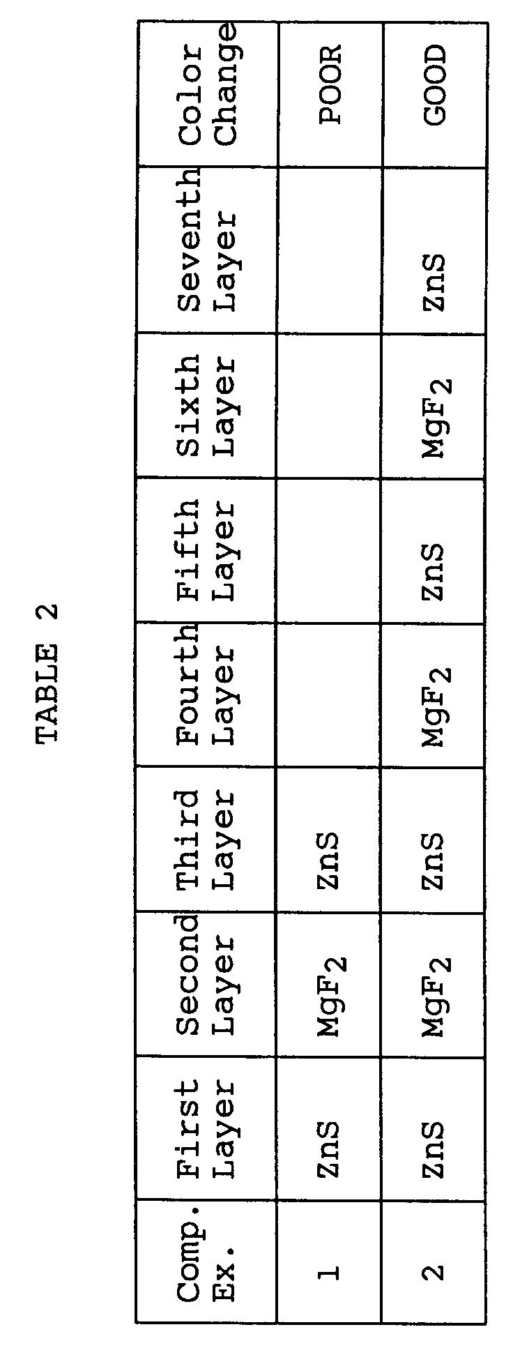
- FIG. 2 shows a variation in the visible spectrum of the experiment example 11. The central wavelength of absorption of visible light incident at right angles was 550 nm, and the spectrum obtained when the visible light was made incident in an oblique direction at an angle of 45 degrees was shifted towards the short-wavelength side as indicated by broken lines and a color change occurred.
- Also, in the experiment examples 12 to 14, the central wavelength of absorption of visible light incident at right angles was 550 nm, and the spectrum obtained when the visible light was made incident in an oblique direction at an angle of 45 degrees was shifted towards the short-wavelength side and a color change occurred, as illustrated in FIG. 2. The absorption level varies in accordance with the material of the transparent evaporated
layer 10. - FIG. 3 shows a variation in the visible spectrum of the comparison example 11. The central wavelength of absorption of visible light incident at right angles was 550 nm, and the spectrum obtained when the visible light was made incident in an oblique direction at an angle of 45 degrees was shifted towards the short-wavelength side as indicated by broken lines but a clear color change did not occur since the half-width value of the spectrum is broad.
- As described above, according to the first embodiment, the transparent hologram seal is formed by laminating the hologram forming layer, transparent evaporated layer, and adhesive layer on the base member, and when required, further laminating the colored layer and adhesion anchor layer on the base member and exhibits the property that a light of specified wavelength range is reflected or transmitted by forming the transparent evaporated layer by laminating a plurality of layers of ceramic material having different refractive indices to a specified thickness, and since the film thickness is changed according to a viewing angle, the optical path length in the thin film is changed and the transmission light or reflected light is observed as a light of different color. Therefore, it is possible to easily determine the real or imitation of the seal according to whether or not the color is changed by changing the viewing angle.
- Next, other embodiments will be explained. In the explanation of the other embodiments, portions which are the same as those of the first embodiment are denoted by the same reference numerals and the explanation therefor is omitted.
- FIG. 4 is a cross sectional view showing the structure of the second embodiment. A
hologram forming layer 4, transparent evaporatedlayer 10,colored layer 12,adhesion anchor layer 14, separating or releasinglayer 18, andadhesive layer 16 are sequentially laminated on the under surface of abase member 2. Also, in the second embodiment, the colored layer and adhesion anchor layer may be omitted. The adhesive strength of the separating or releasinglayer 18 must be set smaller than that of theadhesive layer 16 with respect to a to-be-affixed object to which the seal is affixed, for example, paper or plastic, and may be formed of any material if it satisfies the above condition and has sufficient stability in the succeeding processes. It may be an organic material or inorganic material. For example, thermoplastic acryl resin, chlorinated rubber-series resin, vinyl chloride-vinyl acetate copolymer, cellulosic resin, chlorinated polypropylene, or the above material to which oil silicon, fatty acid amide, or zinc stearate is added may be preferably used. Therefore, the adhesive strength of the adhesive layer may be set larger than that of the releasing layer in a releasing portion (a portion to be left on the to-be-affixed object) and adhesion of the transparent evaporated layer to the base member must be high in a portion to be left on the base member. - The releasing
layer 18 is not uniformly formed on the entire surface, but is formed in a predetermined pattern form. The pattern may be of any form if it can be visually determined, and a specified pattern, mark, characters can be used. The pattern can be formed by use of conventionally known printing means such as gravure or coating means and can be freely selected according to the application. - The second embodiment is an embodiment relating to a brittle seal which cannot be used again after it is separated, the position of the releasing
layer 18 is not limited to the position of FIG. 4 and the releasinglayer 18 may be arranged between thebase member 2 and thehologram forming layer 4 as shown in FIG. 5. Further, the releasinglayer 18 may be arranged between thehologram forming layer 4 and the transparent evaporatedlayer 10, between the transparent evaporatedlayer 10 and thecolored layer 12, or between thecolored layer 12 and theadhesion anchor layer 14. - The state before and after the separation is shown in FIG. 6. FIG. 6 shows an example in which the separation or releasing
layer 18 in a patterned form is arranged between thehologram forming layer 4 and the transparent evaporatedlayer 10. In FIG. 6, for the sake of simplification, a protection layer, adhesion anchor layer, printing layer, and colored layer are not shown and the evaporatedlayer 10 is not shown by a combination of a low-refractive index layer and a high-refractive index layer. - After the
adhesion layer 16 is affixed to a to-be-affixed object 20, the evaporatedlayer 10 is broken when the seal is separated from the to-be-affixed object 20. A part of the evaporatedlayer 10 which corresponds to the patterned separation or releasinglayer 18 is left on the to-be-affixed object 20 (the adhesion layer 16) and the remainder portion of the evaporatedlayer 10 on which the patterned separation or releasinglayer 18 is not formed is affixed to thehologram forming layer 4. As a result, the hologram seal cannot be reused or re-affixed after it is pealed from the to-be-affixed object, thereby preventing an illegal use of the seal. - Next, the results of measurements of variations in visible spectra of the transparent hologram seals with the above structure according to the present invention and hologram seals used for comparison measured by use of an invisible/visible spectrophotometer are shown.
- The base member 2 : a polyester film with a thickness of 12 µm;
The releasing layer 18 : thermoplastic acryl resin having oil silicon added thereto (the releasing layer is formed in a pattern form by gravure);
The low-refractive index layer : magnesium fluoride;
The high-refractive index layer : zinc sulfide;
The number of the layers of the layer 10 : 5;
The thickness of the layer 10 : 1 µm. - The base member 2 : a polyester film with a thickness of 12 µm;
The releasing layer 18 : thermoplastic acryl resin having oil silicon added thereto (the releasing layer is formed in a pattern form by gravure);
The low-refractive index layer : magnesium fluoride;
The high-refractive index layer : zinc sulfide;
The number of the layers of the layer 10 : 7;
The thickness of the layer 10 : 1 µm. - The base member : a polyester film with a thickness of 12 µm;
The releasing layer : thermoplastic acryl resin having oil silicon added thereto (the releasing layer is formed in a pattern form by gravure);
The low-refractive index layer : magnesium fluoride;
The high-refractive index layer : zinc sulfide;
The number of layers of the layer 10 : 3;
The thickness of the layer 10 : 1 µm. - The base member : a polyester film with a thickness of 12 µm;
The releasing layer : thermoplastic acryl resin having oil silicon added thereto (the releasing layer is formed in a pattern form by gravure);
The low-refractive index layer : magnesium fluoride;
The high-refractive index layer : zinc sulfide;
The number of the layers of the layer 10 : 7;
The thickness of the layer 10 : 1 µm. - Color changes of the reflected light caused when a visible light ray is made incident on the hologram seals of the above experiments and the comparison examples used in the first embodiment and the incident direction is changed from the right angles to 45 degrees are shown in the following tables 3 and 4.

- FIG. 7 shows a variation in the visible spectrum of the experiment 21. The central wavelength of absorption of visible light incident at right angles was 550 nm, and the spectrum obtained when the visible light was made incident in an oblique direction at an angle of 45 degrees was shifted towards the short-wavelength side as indicated by broken lines and a color change occurred.
- Also, in the
experiment 22, the central wavelength of absorption of visible light incident at right angles was 550 nm, and the spectrum obtained when the visible light was made incident in an oblique direction at an angle of 45 degrees was shifted towards the short-wavelength side and a color change occurred. - As already explained with reference to FIG. 3, in the visible spectrum of the comparison example 21, the central wavelength of absorption of visible light incident at right angles was 550 nm, and the spectrum obtained when the visible light was made incident in an oblique direction at an angle of 45 degrees was shifted towards the short-wavelength side, but a clear color change did not occur.
- Further, since the seal of the comparison example 22 had a large number of layers, the strength of adhesion of the transparent evaporated layer to the base member was weak and cracks occurred in the transparent evaporated layer when it was bent.
- As described above, according to this embodiment, the hologram seal is formed by laminating the hologram forming layer, transparent evaporated layer, and adhesive layer on the base member, and when required, further laminating the colored layer and adhesion anchor layer on the base member and exhibits the property of permitting a light of specified wavelength range to be reflected or transmitted by forming the transparent evaporated layer by laminating a plurality of layers of ceramic material having different refractive indices to a specified thickness, and since the film thickness is changed according to a viewing angle, the optical path length in the thin film is changed and the transmission light or reflected light is observed as a light of different color. As a result, since the color looks different, it is possible to easily determine the real or imitation of the seal, thus providing an extremely highly reliable forgery preventing effect. Further, since the releasing layer whose adhesion strength is weaker than that of the adhesion layer for affixing the seal to the to-be-affixed object and the seal is divided into two portions along the releasing layer when the seal is separated from the object, the seal cannot be used again.
- FIG. 8 is a cross sectional view showing a transparent hologram transfer foil according to a third embodiment. The hologram transfer foil is similar to the brittle hologram seal. However, the separating or releasing
layer 18 can be freely arranged in the case of the brittle hologram seal but it must be arranged below the base member in the case of the hologram transfer foil. - A
hologram forming layer 4, transparent evaporatedlayer 10,colored layer 12,adhesion anchor layer 14, separating or releasinglayer 18, andadhesive layer 16 are sequentially laminated on the under surface of abase member 2. Also, in the third embodiment, the colored layer and adhesion anchor layer may be omitted. Further, in order to protect thehologram forming layer 4 after transfer, a transparent protection layer may be provided between the releasinglayer 18 and thehologram forming layer 4. As the protection layer, plastic such as polyolefine, polyvinyl chloride, polyvinylidene chloride, polyvinyl alcohol, or polyethylene terephthalate may be used. - After the
adhesion layer 16 is affixed to a to-be-affixed object, only thebase member 2 is separated and the layers under thehologram forming layer 4 are left on the to-be-affixed object when the seal is pealed from the to-be-affixed object. - The releasing
layer 18 can be uniformly formed on the entire surface or formed in a predetermined pattern form in the same manner as in the case of the brittle hologram seal. An embodiment in which the patterned releasing layer is formed will be described next. - FIG. 9A shows the structure of a transfer foil according to a fourth embodiment and the state thereof before and after transfer. A
base member 2, a releasinglayer 18 having a pattern formed therein, ahologram forming layer 4, a transparent evaporatedlayer 10, and anadhesive layer 16 are sequentially laminated. Also, anadhesion anchor layer 14 can be formed between the transparent evaporatedlayer 10 and theadhesive layer 16 as shown in FIG. 9B. Further, although not shown in the drawing, a colored layer can be formed as in the case of the above embodiments. By forming the releasinglayer 18 in the pattern form, only a portion formed on the releasinglayer 18 can be transferred to a to-be-transferred object 20 when a transparenthologram transfer foil 22 is pressed against theobject 22 as shown in FIG. 10, and only those portions of thehologram forming layer 4, transparent evaporatedlayer 10 andadhesive layer 16 which are constructed in the pattern form are formed on theobject 20, thus forming apattern 24 for detection of forgery. - The fourth embodiment may be modified as shown in FIGS. 11A and 11B.
- In the modification shown in FIG. 11A, a
base member 2, a releasinglayer 18, ahologram forming layer 4, a transparent evaporatedlayer 10, and anadhesive layer 16 having a pattern formed therein are sequentially laminated. Also, anadhesion anchor layer 14 can be formed between the transparent evaporatedlayer 10 and theadhesive layer 16 as shown in FIG. 11B Further, although not shown in the drawing, a colored layer can be formed as in the case of the above embodiment. By forming theadhesive layer 16 in the pattern form, only a portion formed on theadhesive layer 18 can be transferred to a to-be-transferred object 20 when a transparenthologram transfer foil 22 is pressed against theobject 22 as shown in FIG. 10, and only those portions of thehologram forming layer 4, transparent evaporatedlayer 10 andadhesive layer 16 which are constructed in the pattern form are formed on theobject 20, thus forming apattern 24 for detection of forgery. - Next, the results of measurements of variations in visible spectra of the transparent hologram seals with the above structure according to the present invention and hologram seals used for comparison measured by use of an invisible/visible spectrophotometer are shown.
- The base member 2 : a polyester film with a thickness of 12 µm;
The releasing layer 18 : thermoplastic acryl resin having oil silicon added thereto (the releasing layer is formed in a pattern form by gravure);
The hologram forming layer 4 : urethane metaacrylate resin;
The low-refractive index layer 8 : silicon dioxide;
The high-refractive index layer 6 : zinc sulfide;
The number of the layers of the layer 10 : 5;
The thickness of the layer 10 : 1 µm. - The base member 2 : a polyester film with a thickness of 12 µm;
The releasing layer 18 : thermoplastic acryl resin having oil silicon added thereto (the releasing layer is formed in a pattern form by gravure);
The hologram forming layer 4 : urethane metaacrylate resin;
The low-refractive index layer 8 : silicon dioxide;
The high-refractive index layer 6 : titanium dioxide;
The number of the layers of the layer 10 : 5;
The thickness of the layer 10 : 1 µm. - The base member 2 : a polyester film with a thickness of 12 µm;
The releasing layer 18 : thermoplastic acryl resin having oil silicon added thereto (the releasing layer is formed in a pattern form by gravure);
The hologram forming layer 4 : urethane metaacrylate resin;
The low-refractive index layer 8 : silicon dioxide;
The high-refractive index layer 6 : zirconium dioxide;
The number of the layers of the layer 10 : 5;
The thickness of the layer 10 : 1 µm. - The base member 2 : a polyester film with a thickness of 12 µm;
The releasing layer 18 : thermoplastic acryl resin having oil silicon added trereto (the releasing layer is formed in a pattern form by gravure);
The hologram forming layer 4 : urethane metaacrylate resin;
The low-refractive index layer 8 : magnesium fluoride;
The high-refractive index layer 6 : zinc sulfide;
The number of the layers of the layer 10 : 5;
The thickness of the layer 10 : 1 µm. - The base member 2 : a polyester film with a thickness of 12 µm;
The releasing layer 18 : thermoplastic acryl resin having oil silicon added thereto (the releasing layer is formed in a pattern form by gravure);
The hologram forming layer 4 : urethane metaacrylate resin;
The low-refractive index layer 8 : magnesium fluoride;
The high-refractive index layer 6 : titanium dioxide;
The number of the layers of the layer 10 : 5;
The thickness of the layer 10 : 1 µm. - The base member 2 : a polyester film with a thickness of 12 µm;
The releasing layer 18 : thermoplastic acryl resin having oil silicon added thereto (the releasing layer is formed in a pattern form by gravure);
The hologram forming layer 4 : urethane metaacrylate resin;
The low-refractive index layer 8 : magnesium fluoride;
The high-refractive index layer 6 : zirconium dioxide;
The number of the layers of the layer 10 : 5;
The thickness of the layer 10 : 1 µm. - The base member 2 : a polyester film with a thickness of 12 µm;
The releasing layer 18 : thermoplastic acryl resin having oil silicon added thereto (the releasing layer is formed in a pattern form by gravure);
The hologram forming layer 4 : urethane metaacrylate resin;
The low-refractive index layer 8 : magnesium oxide;
The high-refractive index layer 6 : zinc sulfide;
The number of the layers of the layer 10 : 5;
The thickness of the layer 10 : 1 µm. - The base member 2 : a polyester film with a thickness of 12 µm;
The releasing layer 18 : thermoplastic acryl resin having oil silicon added thereto (the releasing layer is formed in a pattern form by gravure);
The hologram forming layer 4 : urethane metaacrylate resin;
The low-refractive index layer 8 : magnesium oxide;
The high-refractive index layer 6 : titanium dioxide;
The number of the layers of the layer 10 : 5;
The thickness of the layer 10 : 1 µm. - The base member 2 : a polyester film with a thickness of 12 µm;
The releasing layer 18 : thermoplastic acryl resin having oil silicon added thereto (the releasing layer is formed in a pattern form by gravure);
The hologram forming layer 4 : urethane metaacrylate resin;
The low-refractive index layer 8 : magnesium oxide;
The high-refractive index layer 6 : zirconium dioxide;
The number of the layers of the layer 10 : 5;
The thickness of the layer 10 : 1 µm. - The base member 2 : a polyester film with a thickness of 12 µm;
The releasing layer 18 : thermoplastic acryl resin having oil silicon added thereto (the releasing layer is formed in a pattern form by gravure);
The hologram forming layer 4 : urethane metaacrylate resin;
The low-refractive index layer 8 : magnesium fluoride;
The high-refractive index layer 6 : titanium dioxide;
The number of the layers of the layer 10 : 5;
The thickness of the layer 10 : 1 µm;
The colored layer : formed. - The base member 2 : a polyester film with a thickness of 12 µm;
The releasing layer 18 : thermoplastic acryl resin having oil silicon added thereto (the releasing layer is formed in a pattern form by gravure);
The hologram forming layer 4 : urethane metaacrylate resin;
The low-refractive index layer 8 : magnesium fluoride;
The high-refractive index layer 6 : zirconium dioxide;
The number of the layers of the layer 10 : 5;
The thickness of the layer 10 : 1 µm. - The base member 2 : a polyester film with a thickness of 12 µm;
The releasing layer 18 : thermoplastic acryl resin having oil silicon added thereto (the releasing layer is formed in a pattern form by gravure);
The hologram forming layer 4 : urethane metaacrylate resin;
The low-refractive index layer 8 : magnesium fluoride;
The high-refractive index layer 6 : zirconium dioxide;
The number of the layers of the layer 10 : 5;
The thickness of the layer 10 : 1 µm. - The base member : a polyester film with a thickness of 12 µm;
The releasing layer : thermoplastic acryl resin having oil silicon added thereto (the releasing layer is formed in a pattern form by gravure);
The hologram forming layer : urethane metaacrylate resin;
The low-refractive index layer : magnesium fluoride;
The high-refractive index layer : titanium dioxide;
The number of the layers of the evaporated layer : 3;
The thickness of the evaporated layer : 1 µm. - The base member : a polyester film with a thickness of 12 µm;
The releasing layer : thermoplastic acryl resin having oil silicon added thereto (the releasing layer is formed in a pattern form by gravure);
The hologram forming layer : urethane metaacrylate resin;
The low-refractive index layer : magnesium fluoride;
The high-refractive index layer : titanium dioxide;
The number of the layers of the evaporated layer : 7;
The thickness of the evaporated layer : 1 µm. - Color changes of the reflected light caused when a visible light ray is made incident on the hologram seals of the above experiments and the comparison examples used in the first embodiment and the incident direction is changed from the right angles to 45 degrees are shown in the following tables 5 and 6.


- FIG. 12 shows the visible spectrum of the experiment 41. The central wavelength of absorption of visible light incident at right angles was 550 nm, and the spectrum obtained when the visible light was made incident in an oblique direction at an angle of 45 degrees was shifted towards the short-wavelength side as indicated by broken lines and a color change occurred. Further, the transferability was high.
- Also, as in the case of the experiment 41, in each of the
experiments 42 to 49, 51 and 52, the central wavelength of absorption of visible light incident at right angles was 550 nm, and the spectrum obtained when the visible light was made incident in an oblique direction at an angle of 45 degrees was shifted towards the short-wavelength side and a color change occurred. Further, the transferability was high. - FIG. 13 shows the visible spectrum of the
experiment 50. The central wavelength of absorption of visible light incident at right angles was 550 nm, and the spectrum obtained when the visible light was made incident in an oblique direction at an angle of 45 degrees was shifted towards the short-wavelength side as indicated by broken lines and a color change occurred. Further, the transferability was high. - As shown in FIG. 14, in the visible spectrum of the comparison example 41, the central wavelength of absorption of visible light incident at right angles was 550 nm, and the spectrum obtained when the visible light was made incident in an oblique direction at an angle of 45 degrees was shifted towards the short-wavelength side as indicated by broken lines and the color change was not clear. Further, the strength of adhesion to the to-be-affixed object was high.
- Further, since the seal of the comparison example 42 had a large number of layers, the strength of adhesion of the transparent evaporated layer to the base member was weak and cracks occurred in the transparent evaporated layer when it was partly transferred or bent.
- As described above, like the above embodiment, according to this embodiment, the hologram seal exhibits the property of permitting a light of specified wavelength range to be reflected or transmitted, and since the film thickness is changed according to a viewing angle, the optical path length in the thin film is changed and the transmission light or reflected light is observed as a light of different color. As a result, since the color looks different, it is possible to easily determine the real or imitation of the seal, thus providing an extremely highly reliable forgery preventing effect. Further, since the seal is formed as the transfer foil, it can be easily transferred to a three-dimensional object such as a compact.
- FIG. 15 is a cross sectional view showing the structure of the fifth embodiment. A transparent evaporated
layer 10,print layer 28 andprotection layer 30 are sequentially laminated on abase member 82. The above embodiments relate to the transparent hologram seal or hologram transfer foil attached to another article, but in this embodiment, no hologram is used and theprint layer 28 formed in the pattern form is used. Further, this embodiment has no adhesive layer and relates to a laminated body for real article verification provided as a single unit. However, if thebase member 82 is affixed to the surface of an article, this embodiment becomes the same as the above embodiments. Theprotection layer 30 is used to protect the whole portion of the laminated body and is required to give no optical influence. Theprotection layer 30 exhibits the light transmission property for light in the specified wavelength range, and is formed of resin or the like having good abrasion resistance to provide the protection effect against friction or flaw from the exterior, and hydroxyethyl cellulose, carboxylmethyl cellulose, polyvinyl alcohol, starch, styrene-myelen acid copolymer, single body or copolymer of methacrylic resin such as polymethyl methacrylate or polyethyl methacrylate, resin such as polystyrene, acrylic-styrene copolymer, acrylic resin, polyester resin, chroman resin, ABS resin, or nitrocellulose, resin having fluorine-series resin or silicon-series resin mixed therein, or solution obtained by dissolving or dispersing the resin into solvent such as toluene or xylene is formed by use of the coating or printing method such as the spin-coating method, roll-coating method, knife-edge method, offset printing method, gravure printing method, or screen printing method. Further, as the material of theprotection layer 30, setting resin such as thermosetting resin, ultraviolet-ray setting resin, electron-beam setting resin can be used, and glass or the like can be used if it has the above property. Further, it is necessary to take the thickness into consideration when the refractive index takes a special value. - Like the above embodiment, it is possible to color the
base member 82 or coat the surface thereof if it does not give a bad influence on the visual determination of the transparent evaporatedlayer 10. - Unlike the above embodiment, the laminated body of this embodiment is observed from the
protection layer 30 side. - A predetermined pattern or the like is printed on the
print layer 28, but it is necessary to permit the transparent evaporatedlayer 10 to be observed via a portion other than the pattern portion of theprint layer 28. Theprint layer 28 can be formed by use of the conventionally known printing method or coating method such as gravure printing method. Thebase member 82 is formed of a material which has the property of absorbing light, and since an opticalmulti-layer film 10 is formed on thebase member 82, a color obtained when observing the thin film along a vertical direction or a color extremely similar to the color is used when the print layer is printed in one color, and at least a color obtained when observing the thin film along a vertical direction or a color extremely similar to the color is used when the print layer is printed in two or more colors. - Next, the operation of this embodiment is explained. In this embodiment, a case wherein the
print layer 28 is formed in a stripe pattern is explained. As shown in FIG. 16A, bar-form stripe print layers 28 are arranged at a regular interval and portions of the transparent evaporatedlayer 10 which lie under the print layers are exposed between the print layers 28. In this case, as described before, since the color of theprint layer 28 is the same as or extremely similar to the color of the transparent evaporatedlayer 10 observed when it is viewed in the vertical direction, it is impossible to distinguish theprint layer 28 and the transparent evaporatedlayer 10 from each other as shown in FIG. 16B when they are viewed in the vertical direction. - However, as shown in FIG. 17A, since the transparent evaporated
layer 10 is constructed by alternately laminating ceramic layers having different refractive indices to a specified thickness, the optical path length in thethin film 10 is changed and the color of the transmission light or reflected light is observed as a light of different color when the laminated body is viewed in an oblique direction, and as a result, as shown in FIG. 17B, a color difference or hue difference occurs between the transparent evaporatedlayer 10 and theprint layer 28 whose color is kept unchanged irrespective of the viewing angle and the presence of the transparent evaporatedlayer 10 can be easily determined. - Thus, when the laminated body of the present invention is viewed in a certain direction, the print layer and the transparent evaporated layer cannot be distinguished from each other, but when it is viewed in a different direction, the print layer and the transparent evaporated layer come to have different hues, thereby making it possible to easily determine the presence or absence of a specified transparent evaporated layer.
- The color of the
print layer 28 is not necessarily set similar to the color of the transparent evaporated layer displayed when it is viewed in a vertical direction and it is satisfactory only if the print layer and the transparent evaporated layer can be distinguished from each other when the viewing direction is changed. Further, theprint layer 28 can be formed in a desired pattern such as a character, numeral or pattern other than the stripe pattern. - Next, the results of measurements of variations in visible spectra of the laminated bodies with the above structure measured by use of an invisible/visible spectrophotometer are shown.
- The base member 82 : a black polyester film with a thickness of 25 µm;
The low-refractive index layer 8 : silicon dioxide;
The high-refractive index layer 6 : titanium dioxide;
The number of layers of the layer 10 : 5;
The film thickness of the layer 10 : 1 µm. - The base member : a soda glass with a thickness of 1 mm;
The low-refractive index layer 8 : silicon dioxide;
The high-refractive index layer 6 : titanium dioxide;
The number of layers of the layer 10 : 5;
The thickness of the layer 10 : 1 µm. - FIG. 18 shows a variation in the visible spectrum of the experiment 55. The central wavelength of absorption of visible light incident at right angles was 550 nm, and the spectrum obtained when the visible light was made incident in an oblique direction at an angle of 45 degrees was shifted towards the short-wavelength side as indicated by broken lines and a color change occurred. Thus, since the
print layer 28 was formed by forming a pattern of printing ink of the same color as that which was observed when the transparent evaporatedlayer 10 was viewed in the vertical direction, the color of theprint layer 28 was not changed but the color of the transparent evaporatedlayer 10 was changed when the viewing angle was changed, thereby making it possible to clearly determine the pattern of theprint layer 28. - Also, in the
experiment 56, the central wavelength of absorption of visible light incident at right angles was 550 nm, and the spectrum obtained when the visible light was made incident in an oblique direction at an angle of 45 degrees was shifted towards the short-wavelength side and a color change occurred. - As described above, according to this embodiment, the print layer is formed in the pattern form on the transparent evaporated layer and the color of the print layer is set similar to the color of the transparent evaporated layer displayed when it is viewed in a predetermined direction so that the hue difference between the transparent evaporated layer and the print layer will be changed by changing the viewing angle, and therefore, the transparent evaporated layer which could not be distinguished from the print layer comes to be easily observed or the transparent evaporated layer which could be easily observed will come to have the same color as the print layer and cannot be distinguished from the print layer. Thus, it is possible to easily determine the real or imitation of the laminated body.
- FIG. 19 is a cross sectional view showing the structure of the sixth embodiment. A metal deposited
layer 34, transparent evaporatedlayer 10 andtransparent protection layer 38 are sequentially laminated on abase member 2. In this embodiment, the laminated body is viewed from above theprotection layer 38. As shown in FIG. 20, it possible to form the transparent evaporatedlayer 10 andtransparent protection layer 38 on ametal foil 36 instead of using thebase member 2. - The metal deposited
layer 34 is preferably formed of a material of high reflection factor and can be formed of gold, aluminum, chrome, nickel or the like. Themetal foil 36 is used as a reflection layer and a base member and can be formed of gold, aluminum, chrome, nickel or the like. Theprotection layer 38 is formed of a high polymer film whose refractive index is lower than that of a high-refractive indexceramic layer 6. - Thus, in this embodiment, since the reflection layer is provided, a sharp absorption characteristic can be attained for light rays of specified wavelengths. The half-width value of the absorption band is 20 nm or less and is outside the range of color which can be recognized by human eyes. The peak value of the absorption band obtained when a light ray is made incident on the laminated body at right angles is shifted towards the short-wavelength side and a color variation caused at this time cannot be recognized by the human eyes. The shift amount varies according to the optical thin film, but is approx. several ten nm and can be sufficiently read by use of an optical instrument. That is, in this embodiment, the real or imitation can be determined by detecting the reflected light by use of the optical instrument instead of the human eyes.
- Next, the results of measurements of variations in the visible spectra of this embodiment with the above structure measured by use of an invisible/visible spectrophotometer are shown.
- The base member 2 : a transparent polyester film with a thickness of 12 µm;
The metal deposited layer 34 : a layer obtained by vapor-depositing aluminum to a thickness of 1000 Å by the vacuum deposition method;
The low-refractive index layer 8 : silicon dioxide;
The high-refractive index layer 6 : titanium dioxide;
The number of layers of the layer 10 : 5;
The thickness of the layer 10 : 1 µm. - The central wavelength of maximum absorption of the visible light perpendicular to the film in the visible range in this experiment was 620 nm as shown in FIG. 21. When the light is made incident in a direction at an angle of 45 degrees, the central wavelength is shifted towards the short-wavelength side as indicated by broken lines in the drawing.
- The base member : an
aluminum foil 36 with a thickness of 12 µm;
The low-refractive index layer 8 : silicon dioxide;
The high-refractive index layer 6 : titanium dioxide;
The number of layers layer 10 : 5;
The thickness of the layer 10 : 1 µm. - Like the characteristic shown in FIG. 21, in the optical characteristic of this experiment, the central wavelength is shifted towards the short-wavelength side when the light is made incident in a direction at an angle of 45 degrees.
- As described above, according to this embodiment, since two types of ceramic layers having different refractive indices are laminated on the metal deposited layer or metal foil, the spectrum of the reflected light is slightly changed according to the angle. By detecting the change by use of a detector, the real or imitation of the laminated body can be determined.
- FIG. 22 is a cross sectional view showing the structure of the seventh embodiment. A
hard protection layer 40 is formed on the top surface of abase member 2, and a transparent evaporatedlayer 10, athin film layer 42 formed of an element of III to VI group, the oxide, carbide, nitride, or boride thereof, acolored layer 12, anadhesion anchor layer 14, and anadhesive layer 16 are sequentially laminated on the under surface of thebase member 2. Thecolored layer 12, andadhesion anchor layer 14 can be omitted. - As the
hard protection layer 40, a hard transparent thin film formed of a chemically stable material such as diamond, diamond-like carbon, silicon carbide, aluminum oxide, silicon oxide, or boron nitride is used, for example. This can enhance the resistance to abrasion and the resistance to chemical attack and can enhance the durability under the severe service condition. Thus, the forgery preventing ability of the seal and the decorative effect can be maintained for a long period of time. - Generally, if the
adhesive layer 16 is formed to add the function of a seal after ceramics layers 6 and 8 with different refractive indices are sequentially laminated, the refractive index of the transparent evaporatedlayer 10 which is set in contact with theadhesive layer 16 is changed to deteriorate the optical characteristic of the transparent evaporatedlayer 10. Further, if the adhesion strength between thebase member 2 and the transparent evaporatedlayer 10 is insufficient, cracks may occur in the transparent evaporatedlayer 10 because of the volume contraction caused by curing of the adhesive agent. For this reason, the simplicity of determination between the real or imitation of the article which is the requirement characteristic of the forgery preventing seal is lowered and the decorative effect and the color thereof obtained when it is visually observed are deteriorated. An object to which the seal is affixed is mainly a card, video cassette case or the like which is required to be prevented from being forged. Since these articles are daily used by various people, it is particularly required to have the excellent durability in the severe service condition. However, since a high polymer film such as polyester or polyolefine is generally used as thebase member film 2 used as the top surface layer of the seal, it cannot be said that a sufficiently high performance in the severe service condition, for example, the excellent durability can be attained. By forming theprotection layer 40, the above problem can be solved. - The
thin film layer 42 is formed of diamond-like carbon, silicon carbide or boron carbide, for example. Thethin film 42 is preferably formed of a material of high refractive index. In order to form thethin film layer 42 as a transparent layer, diamond (n = 2.2 to 2.4), diamond-like carbon (n = 2.1 to 2.3), silicon carbide (n = 2.4 to 2.6), or boron nitride (n = 2.0 to 2.2) may be used as the material thereof, and in order to form thethin film layer 42 as an opaque layer, diamond-like carbon (n = 2.1 to 2.3), silicon carbide (n = 2.4 to 2.6), or boron nitride (n = 2.0 to 2.2) may be used as the material thereof. - Since the
base member 2 is a high polymer film formed of organic polymer, the refractive index thereof is low and it is necessary to form a layer arranged in contact with thebase member 2 by use of a material of high refractive index. A transparent evaporated layer (multi-layer interference film) 10 is formed by alternately laminating high-refractive index layers 6 and low-refractive index layers 8 based on the optical interference theory and the spectral characteristic varies according to the number of layers. The number of layers including thebase member 2 is even but the number of themulti-layer interference film 10 is odd in this embodiment. - The
thin film layer 42 is formed of an element of III to VI group, the oxide, carbide, nitride, or boride thereof. By thus forming thethin film 42 which is hard or rigid and chemically stable and has a high-refractive index, theadhesive layer 16 can be formed without deteriorating the spectral characteristic of the multi-layer interference layers while occurrence of a variation in the refractive index of the transparent evaporated layer set in contact with theadhesive layer 16 caused when the adhesive layer is formed can be prevented and occurrence of cracks in the transparent evaporatedlayer 10 due to the volume contraction caused by curing of the adhesive agent and the insufficient adhesion strength between thebase member 2 and the transparent evaporatedlayer 10. - By making the
thin film layer 42 transparent or opaque, the spectral characteristic of the transmission light or reflected light can be freely set according to the color of the thin film layer in addition to the number of layers and the film thickness, the decorative effect and forgery preventing effect can be enhanced and the added value can be made high. - Next, the results of measurements of variations in visible spectra of the laminated bodies of this embodiment with the above structure measured by use of an invisible/visible spectrophotometer are shown.
- The base member 2 : a polyester film with a thickness of 25 µm;
The low-refractive index layer 8 : silicon dioxide;
The high-refractive index layer 6 : zirconium oxide;
The number of layers of the layer 10 : 5;
The thickness of the layer 10 : 1 µm;
The hard protection film : transparent boron nitride. - The central wavelength of maximum absorption of the visible light perpendicular to the film in the visible range in the transparent evaporated layer was 550 nm. When the light is made incident in a direction at an angle of 45 degrees, the central wavelength is shifted towards the short-wavelength side. When visually observing the film, a transmission light of bluish purple color could be observed when viewing the film in the vertical direction and a transmission light of reddish purple color could be observed when viewing the film in an oblique direction at an angle of 45 degrees, and thus it was excellent in the simplicity of determination and the decorative effect. The adhesion strength of the transparent evaporated layer to the base member was sufficient. It is preferable to set the total film thickness of the transparent evaporated
layer 10 to 1 µm or less. If it is set to be larger than 1 µm, the flexibility thereof becomes insufficient, thereby causing cracks in the transparent evaporated layer and degrading the optical characteristic thereof. - The base member : a polyester film with a thickness of 25 µm;
The low-refractive index layer 8 : magnesium fluoride;
The high-refractive index layer 6 : zinc sulfide;
The number of layers of the layer 10 : 5;
The thickness of the layer 10 : 1.5 µm;
The hard protection film : black and opaque diamond-like carbon. - The visible light in the vertical direction cannot pass because of the presence of the black and opaque diamond-like carbon. When visually observing the film, a reflected light of golden color could be observed when viewing the film in the vertical direction and a transmission light of bluish green color could be observed when viewing the film in an oblique direction at an angle of 45 degrees, and thus it was excellent in the simplicity of determination and the decorative effect. The adhesion strength of the transparent evaporated layer to the base member was sufficient.
- The base member : a polyester film with a thickness of 25 µm;
The low-refractive index layer 8 : silicon dioxide;
The high-refractive index layer 6 : zirconium oxide;
The number of layer of the layer 10 : 5;
The thickness of the layer 10 : 1 µm;
The hard protection film : transparent diamond-like carbon thinner than that of theexperiment 72. - The central wavelength of maximum absorption of the visible light perpendicular to the film in the visible range of the transparent evaporated layer was 550 nm. When the light is made incident in a direction at an angle of 45 degrees, the central wavelength is shifted towards the short-wavelength side. When visually observing the film, a transmission light of bluish purple color (which is a complementary color of golden color in the experiment 72) could be observed when viewing the film in the vertical direction and a transmission light of reddish purple color could be observed when viewing the film in an oblique direction at an angle of 45 degrees, and thus it was excellent in the simplicity of determination and the decorative effect. The adhesion strength of the transparent evaporated layer to the base member was sufficient.
- The base member : a polyester film with a thickness of 25 µm;
The low-refractive index layer 8 : silicon dioxide;
The high-refractive index layer 6 : titanium dioxide;
The number of layer of the layer 10 : 5;
The thickness of the layer 10 : 1 µm;
The hard protection film : transparent diamond-like carbon. - The central wavelength of maximum absorption of the visible light perpendicular to the film in the visible range of the transparent evaporated layer was 550 nm. When the light is made incident in a direction at an angle of 45 degrees, the central wavelength is shifted towards the short-wavelength side. When visually observing the film, a transmission light of bluish purple color could be observed when viewing the film in the vertical direction and a transmission light of reddish purple color could be observed when viewing the film in an oblique direction at an angle of 45 degrees, and thus it was excellent in the simplicity of determination and the decorative effect. The adhesion strength of the transparent evaporated layer to the base member was sufficient.
- The base member : a polyester film with a thickness of 25 µm;
The low-refractive index layer 8 : cerium fluoride;
The high-refractive index layer 6 : cerium dioxide;
The number of layer of the layer 10 : 5;
The thickness of the layer 10 : 1 µm;
The hard protection film : transparent silicon carbide. - The central wavelength of maximum absorption of the visible light perpendicular to the film in the visible range of the transparent evaporated layer was 550 nm. When the light is made incident in a direction at an angle of 45 degrees, the central wavelength is shifted towards the short-wavelength side. When visually observing the film, a transmission light of bluish purple color could be observed when viewing the film in the vertical direction and a transmission light of reddish purple color could be observed when viewing the film in an oblique direction at an angle of 45 degrees, and thus it was excellent in the simplicity of determination and the decorative effect. The adhesion strength of the transparent evaporated layer to the base member was sufficient.
- The base member : a polyester film with a thickness of 25 µm;
The low-refractive index layer 8 : silicon dioxide;
The high-refractive index layer 6 : zirconium oxide;
The number of layer of the layer 10 : 5;
The thickness of the layer 10 : 1 µm;
The thin film layer : transparent boron nitride;
The hard protection film : transparent boron nitride. - The central wavelength of maximum absorption of the visible light perpendicular to the film in the visible range of the transparent evaporated layer was 550 nm. When the light is made incident in a direction at an angle of 45 degrees, the central wavelength is shifted towards the short-wavelength side. When visually observing the film, a transmission light of bluish purple color could be observed when viewing the film in the vertical direction and a transmission light of reddish purple color could be observed when viewing the film in an oblique direction at an angle of 45 degrees, and thus it was excellent in the simplicity of determination and the decorative effect. The adhesion strength of the transparent evaporated layer to the base member was sufficient. The seal of this embodiment was affixed to a polyvinyl chloride plate and rubbed with steel wool (Bon-star (trade mark) No. 00) made by NIPPON STEEL WOOL Co., but no scar was made because of the presence of the hard protection layer and it was excellent in the resistance to abrasion.
- The base member : a polyester film with a thickness of 25 µm;
The low-refractive index layer 8 : silicon dioxide;
The high-refractive index layer 6 : titanium dioxide;
The number of layer of the layer 10 : 5;
The thickness of the layer 10 : 1 µm;
The hard protection film : transparent diamond-like carbon. - The central wavelength of maximum absorption of the visible light perpendicular to the film in the visible range of the transparent evaporated layer was 550 nm. When the light is made incident in a direction at an angle of 45 degrees, the central wavelength is shifted towards the short-wavelength side. When visually observing the film, a transmission light of bluish purple color could be observed when viewing the film in the vertical direction and a transmission light of reddish purple color could be observed when viewing the film in an oblique direction at an angle of 45 degrees, and thus it was excellent in the simplicity of determination and the decorative effect. The adhesion strength of the transparent evaporated layer to the base member was sufficient. The seal of this embodiment was affixed to a polyvinyl chloride plate and rubbed with steel wool (Bon-star No. 00) made by NIPPON STEEL WOOL Co., but no scar was made because of the presence of the hard protection layer and it was excellent in the resistance to abrasion.
- The base member : a polyester film with a thickness of 25 µm;
The low-refractive index layer 8 : silicon dioxide;
The high-refractive index layer 6 : titanium dioxide;
The number of layer of the layer 10 : 5;
The thickness of the layer 10 : 1 µm. - The central wavelength of maximum absorption of the visible light perpendicular to the film in the visible range of the transparent evaporated layer was 550 nm. When the light is made incident in a direction at an angle of 45 degrees, the central wavelength is shifted towards the short-wavelength side. When visually observing the film, a transmission light of light bluish purple color could be observed when viewing the film in the vertical direction and a transmission light of light reddish purple color could be observed when viewing the film in an oblique direction at an angle of 45 degrees, but the color was light and a variation in the color was not clear, and it was inferior in the simplicity of determination and the decorative effect. The adhesion strength of the transparent evaporated layer to the base member was sufficient.
- The base member : a polyester film with a thickness of 25 µm;
The low-refractive index layer 8 : magnesium fluoride;
The high-refractive index layer 6 : zinc sulfide;
The number of layer of the layer 10 : 5;
The thickness of the layer 10 : 1 µm. - The central wavelength of maximum absorption of the visible light perpendicular to the film in the visible range of the transparent evaporated layer was 550 nm. When the light is made incident in a direction at an angle of 45 degrees, the central wavelength is shifted towards the short-wavelength side. When visually observing the film, a transmission light of light bluish purple color could be observed when viewing the film in the vertical direction and a transmission light of light reddish purple color could be observed when viewing the film in an oblique direction at an angle of 45 degrees, and a variation in the color was clear, but cracks occurred in the transparent evaporated layer and it was extremely low in the decorative effect and the quality of the seal. The adhesion strength of the transparent evaporated layer to the base member was insufficient.
- The base member : a polyester film with a thickness of 25 µm;
The low-refractive index layer 8 : silicon dioxide;
The high-refractive index layer 6 : titanium dioxide;
The number of layer of the layer 10 : 5;
The thickness of the layer 10 : 1 µm. - The central wavelength of maximum absorption of the visible light perpendicular to the film in the visible range of the transparent evaporated layer was 550 nm. When the light is made incident in a direction at an angle of 45 degrees, the central wavelength is shifted towards the short-wavelength side. When visually observing the film, a transmission light of light bluish purple color could be observed when viewing the film in the vertical direction and a transmission light of light reddish purple color could be observed when viewing the film in an oblique direction at an angle of 45 degrees, but it was light in color and a variation in the color was not clear, and it was inferior in the simplicity of determination and the decorative effect. The adhesion strength of the transparent evaporated layer to the base member was sufficient. When it was rubbed, many scars were made on the entire surface and it was low in the resistance to abrasion.
- Color changes of the reflected light caused when a visible light ray is made incident on the films of the above experiments and comparison examples and the incident direction is changed from the right angles to 45 degrees are shown in the following tables 7 and 8.

- In the above tables, DLC indicates diamond-like carbon.
- As described above, according to this embodiment, by forming the thin film layer which is hard or rigid and chemically stable and has a high-refractive index by use of an element of III to VI group, the oxide, carbide, nitride, or boride thereof, the adhesive layer can be formed without deteriorating the optical characteristic of the transparent evaporated layer.
- FIG. 23 is a cross sectional view showing the structure of the eighth embodiment relating to a copying-inhibited printed matter which can be prevented from being dishonestly copied. A transparent evaporated
layer 10,print layer 54 andprotection layer 56 are sequentially laminated on the upper surface of abase member 52. - The
base member 52 can be any type of material such as a sheet of paper, high polymer film or metal foil if it is used as a printed matter, but the surface thereof is preferably made smooth. Preferably, if a sheet of paper is used as the printed matter, it is desired to use the paper whose surface is subjected to the surface-filling process. More preferably, it is desired to use a colored base member as thebase member 52 in order to fully achieve the copying-inhibiting function according to the present invention. In the case of a metal foil, any metal among aluminum, chrome, nickel, copper and gold can be used. The thickness of thebase member 52 is set to such a thickness as to maintain the flexibility thereof. - A method for forming the
print layer 54 is not limitative, but if theprint layer 54 is formed on the entire surface of thebase member 52, the function of the present invention cannot be attained. Therefore, preferably, it is desired to print characters or a simple pattern on thebase member 52 in the present invention. - The
protection layer 56 is required to have a refractive index different from that of a layer (in this case, the high-refractive index layer 6) of the transparent evaporatedlayer 10 which lies on the protection layer side. Since the refractive index of 1.5 to 1.7 can be attained and is different from that of the high-refractive index layer 6 if high polymer is used, the above condition can be satisfied. Further, theprotection layer 54 may be formed of ceramics such as silicon dioxide or titanium dioxide, or organic hard protection film of diamond-like carbon (DLC) or the like. - Since the color tone of the transparent evaporated
layer 10 is dependent on the viewing angle, it can be copied only in one color when it is copied by use of a coping machine, and thus it can be used as a printed matter effective for forgery prevention. - The position of the
print layer 54 is not limited to a position between the transparent evaporatedlayer 10 and theprotection layer 56, but may be set between thebase member 52 and the transparent vapor-deposition layer 10 as shown in FIG. 24. - Next, the results of measurements of variations in visible spectra of this embodiment with the above structure measured by use of an invisible/visible spectrophotometer are shown.
- The base member 52 : a black polyester film with a thickness of 50 µm;
The low-refractive index layer 8 : silicon dioxide;
The high-refractive index layer 6 : titanium dioxide;
The number of layer of the layer 10 : 5;
The thickness of the layer 10 : 1 µm. - The central wavelength of maximum absorption of the visible light perpendicular to the film in the visible range of the transparent evaporated layer was 580 nm. When the light is made incident in a direction at an angle of 45 degrees, the central wavelength is shifted towards the short-wavelength side. The color of the printed matter copied in color was golden, but the color was not changed when the viewing angle was changed, and thus the real or imitation thereof could be easily determined.
- The base member 52 : paper whose surface is subjected to the filling process and which has a thickness of 100 µm;
The low-refractive index layer 8 : silicon dioxide;
The high-refractive index layer 6 : titanium dioxide;
The number of layer of the layer 10 : 5;
The thickness of the layer 10 : 1 µm. - The central wavelength of maximum absorption of the visible light perpendicular to the film in the visible range of the transparent evaporated layer was 580 nm. When the light is made incident in a direction at an angle of 45 degrees, the central wavelength is shifted towards the short-wavelength side. The color of the printed matter copied in color was yellow, but the color was not changed when the viewing angle was changed, and thus the real or imitation thereof could be easily determined.
- The base member 52 : an aluminum foil with a thickness of 20 µm;
The low-refractive index layer 8 : silicon dioxide;
The high-refractive index layer 6 : titanium dioxide;
The number of layer of the layer 10 : 5;
The thickness of the layer 10 : 1 µm. - The central wavelength of maximum absorption of the visible light perpendicular to the film in the visible range of the transparent evaporated layer was 580 nm. When the light is made incident in a direction at an angle of 45 degrees, the central wavelength is shifted towards the short-wavelength side. The color of the printed matter copied in color was yellow, but the color was not changed when the viewing angle was changed, and thus the real or imitation thereof could be easily determined.
- The base member 52 : paper whose surface is subjected to the filling process and which has a thickness of 100 µm;
The low-refractive index layer 8 : silicon dioxide;
The high-refractive index layer 6 : titanium dioxide;
The number of layer of the layer 10 : 5;
The thickness of the layer 10 : 1 µm. - The central wavelength of maximum absorption of the visible light perpendicular to the film in the visible range of the transparent evaporated layer was 580 nm. When the light is made incident in a direction at an angle of 45 degrees, the central wavelength is shifted towards the short-wavelength side. The color of the printed matter copied in color was yellow, but the color was not changed when the viewing angle was changed, and thus the real or imitation thereof could be easily determined.
- The base member : paper whose surface is subjected to the filling process and which has a thickness of 100 µm;
The low-refractive index layer 8 : silicon dioxide;
The high-refractive index layer of the transparent evaporated layer : titanium dioxide;
The number of layer of the layer 10 : 5;
The thickness of the layer 10 : 1 µm. - The central wavelength of maximum absorption of the visible light perpendicular to the film in the visible range of the transparent evaporated layer was 580 nm. When the light is made incident in a direction at an angle of 45 degrees, the central wavelength is shifted towards the short-wavelength side. The color of the printed matter copied in color was yellow, but the color was not changed when the viewing angle was changed, and thus the real or imitation thereof could be easily determined.
- The results of evaluation of the above experiments 81 to 86 are shown in the following table 9.
TABLE 9 Ex. Base Member Maximum Absorption Wavelength (nm) Tone Variation Possibility of Copying 81 Polyester Film 580 Ⓞ X 82 Surface-Filled Paper 580 ○ X 83 Aluminum Foil 580 △ X 84 Surface-Filled Paper 580 ○ X 85 Surface-Filled Paper 580 ○ X 86 Surface-Filled Paper 580 ○ X - In the above table, Ⓞ indicates a significant variation, ○ indicates a recognizable variation, △ indicates a slightly recognizable variation, and X indicates that no color tone variation occurs in the copy.
- If the laminated body of the above embodiment is affixed to a document which is required to be prevented from being copied and when the document is copied, the real or imitation of the document can be easily determined by checking the color of the laminated body while changing the viewing direction.
- FIG. 25 is a cross sectional view showing the structure of the ninth embodiment. A
reflection layer 62, transparent evaporatedlayer 10 andprotection layer 64 are sequentially laminated on abase member 60. The transparent evaporatedlayer 10 is partially formed. For example, the transparent evaporatedlayer 10 is formed in a pattern form on thebase member 60 so that the transparent evaporated layer may be formed on part of the base member and will not be formed in the remaining portion of the base member. Alternatively, the transparent evaporatedlayer 10 is formed of a plurality of ceramic layers having different refractive indices as described before, and part of the transparent evaporatedlayer 10 may be formed to have a different number of ceramic layers from that of the remaining portion or the total film thickness thereof may be made different from that of the remaining portion. Such a structure can be obtained by destroying the entire portion or part of the transparent evaporated layer by sputtering, etching or the like or forming the layer with a larger or smaller film thickness at the time of film formation. With the above structure, the intensity or position of the spectra of the absorption band and reflection band is changed in part of the transparent evaporated layer. - The
base member 60 can be formed of any material if it can support the transparent evaporatedlayer 10, and may be a plastic card such as a cash card or credit card, prepaid card used for transportation means or telephones, or a sheet of paper such as an admission ticket for the site for amusements or exhibition. Further, the type thereof can be a seal or transfer foil. As the material of thebase member 60, polyvinyl chloride or the like can be used. Thereflection layer 62 is provided to reflect the incident light from the light source of the detection device as will be described later and can be formed of gold, nickel, chrome or the like. - Like the above embodiment, the film thickness of the evaporated
layer 10 is controlled so that it can have an absorption band in a specified wavelength range. - The
protection layer 64 is used to protect the transparent evaporatedlayer 10 when thelayer 10 is formed of soft ceramic such as zinc sulfide. The laminated body of this embodiment is observed from theprotection layer 64 side. - FIG. 26 is a view showing-the schematic structure of the detection device for the laminated body. A
slit 72 is disposed on the front side of alight source 71 to form a slit light source. Thelight source 71 projects a light to thelaminated body 73 in the vertical direction. A reflected light traveling in an oblique direction at an angle of 45 degrees is detected by anoptical sensor 74. Thelight source 71 andoptical sensor 74 are fixed and thelaminated body 73 moves with respect to thelight source 71 andoptical sensor 74. Thelight source 71 can preferably emit a stable light in the absorption wavelength range. Further, it is preferable that the emission light is not a homogeneous light but a light in a wide wavelength range. In this example, as the emission light, a visible light whose wavelength is in the range of 400 nm to 700 nm or 800 nm is used. - The
optical sensor 74 is formed of diffraction grating or photodiode array. In order to enhance the sensitivity of the optical sensor in the absorption wavelength range and in order to permit the precision thereof to be freely set, it is preferable to use the photodiode array. In this example, a plurality of photodiodes each of which can detect a light with a wavelength width of 0.5 to 2 nm are arranged to form a photodiode array. With the photodiode array, a light subjected to the spectral diffraction can be instantaneously detected. Further, it becomes possible to easily limit the wavelength by use of several prisms. In order to detect the light, it is possible to detect the light by converting the light passing the prism into an electrical signal by a photomultiplier, but in this case, it is not preferable because a time variation is large and a relatively long time is necessary for one reading. - The selective transmission for light in a specified wavelength range in the visible light is determined by the transparent evaporated
layer 10. Since thereflection layer 62 is provided, sharp absorption is observed for light rays of specified wavelengths and the half-width value of the absorption band is 20 nm or less and is outside the range of color variation which can be recognized by human eyes. The peak value of the absorption band obtained when a light ray is made incident on the laminated body in an oblique direction is shifted towards the short-wavelength side in comparison with a case wherein a light ray is made incident on the laminated body at right angles and a color variation caused at this time cannot be recognized by the human eyes, but in this embodiment, the color variation is detected by use of a device. The shift amount and half-width value can be adjusted according to the thickness of the evaporatedlayer 10 and can be changed according to the application and purpose thereof. - Next, the results of measurements of variations in visible spectra of the embodiment with the above structure measured by use of an invisible/visible spectrophotometer are shown.
- The base member 60 : vinyl chloride;
The reflection layer 62 : aluminum;
The pattern of the layer 10 : mosaic form shown in FIG. 27A;
The low-refractive index layer 8 : silicon dioxide;
The high-refractive index layer 6 : titanium dioxide;
The number of layers of the layer 10 : 5. - When the reflected light was detected by the
optical sensor 74 in an oblique direction at 45 degrees with respect to the vertical incident light, a response signal as shown in FIG. 27B was obtained. - This is similar to the experiment 91 except that the pattern of the evaporated
layer 10 is a stripe form as shown in FIG. 28A. - When the reflected light was detected by the
optical sensor 74 in an oblique direction at 45 degrees with respect to the vertical incident light, a response signal as shown in FIG. 28B was obtained. - This is similar to the experiment 91 except that the pattern of the evaporated
layer 10 is a desired picture-like form as shown in FIG. 29A. - When the reflected light was detected by the
optical sensor 74 in an oblique direction at 45 degrees with respect to the vertical incident light, a response signal as shown in FIG. 29B was obtained. - This is similar to the experiment 91 except that the number of layers of the
layer 10 is 3. - When the reflected light was detected by the
optical sensor 74 in an oblique direction at 45 degrees with respect to the vertical incident light, a degraded response signal as shown in FIG. 30 was obtained. - As described above, according to this embodiment, the real or imitation of the laminated body can be determined by detecting the reflected light which is oblique with respect to the laminated body having the reflection layer, and an imitation of an article can be easily recognized by affixing the laminated body to the article.
- Since this embodiment can record a bar-code by a patterned evaporated
layer 10, it can be applied to a magnetic card (the laminated body is affixed to the magnetic card). As a result, the forgery preventing function can be made more effectively and easily. - Additional advantages and modifications will readily occur to those skilled in the art. Therefore, the present invention in its broader aspects is not limited to the specific details, representative devices, and illustrated examples shown and described herein. Accordingly, various modifications may be made without departing from the spirit or scope of the general inventive concept as defined by the appended claims and their equivalents. For example, the thickness or the number of ceramic layers constructing the transparent evaporated layer can be adequately set.
- A hologram forming layer (4), transparent evaporated layer (10), colored layer (12), adhesion anchor layer (14), and adhesive layer (16) are sequentially laminated on the under surface of a base member (2). The laminated body is used as a seal by the presence of the adhesive layer (16). It is preferable for the base member (2) to have adequate rigidity (flexibility, tensile strength) and surface flatness. The hologram forming layer (4) has a relief type hologram image. The transparent evaporated layer (10) is a multi-layered ceramic layer constructed by alternately laminating high-refractive index layers (6) and low-refractive index layers (8) and the thickness thereof is preferably set to 1 µm or less. In the transparent evaporated layer (10), the color of visible light in predetermined wavelength range is changed according to the viewing angle when it is transmitted therethrough or reflected therefrom.
Claims (15)
- A laminated body characterized by comprising:
a base member;
a hologram layer formed on said base member;
a transparent evaporated layer formed on said hologram layer and constructed by a laminated structure of first and second ceramic materials having different refractive indices; and
an adhesive layer formed on said transparent evaporated layer. - A laminated body characterized by comprising:
a base member;
a separating layer formed on said base member;
a hologram layer formed on said separating layer;
a transparent evaporated layer formed on said hologram layer and constructed by a laminated structure of first and second ceramic materials having different refractive indices; and
an adhesive layer formed on said transparent evaporated layer. - A laminated body characterized by comprising:
a base member;
a hologram layer formed on said base member;
a transparent evaporated layer formed on said hologram layer and constructed by a laminated structure of first and second ceramic materials having different refractive indices;
a separating layer formed on said transparent evaporated layer; and
an adhesive layer formed on said separating layer. - A laminated body characterized by comprising:
a base member;
a transparent evaporated layer formed on said base member and constructed by a laminated structure of first and second ceramic materials having different refractive indices; and
a print layer formed on said transparent evaporated layer and having a predetermined printed pattern. - A laminated body characterized by comprising:
a reflective base member; and
a transparent evaporated layer formed on said base member and constructed by a laminated structure of first and second ceramic materials having different refractive indices. - A laminated body characterized by comprising:
a base member;
a print layer formed on said base member and having a predetermined printed pattern; and
a transparent evaporated layer formed on said print layer and constructed by a laminated structure of first and second ceramic materials having different refractive indices.
- A laminated body characterized by comprising: a reflective base member; and
a transparent evaporated layer partially formed on parts of said base member and constructed by a laminated structure of first and second ceramic materials having different refractive indices. - A laminated body characterized by comprising:
a reflective base member; and
a transparent evaporated layer partially formed on said base member and constructed by a laminated structure of first and second ceramic materials having different refractive indices, the number of the laminated structure being different on parts of said base member. - A laminated body characterized by comprising:
a reflective base member; and
a transparent evaporated layer partially formed on said base member and constructed by a laminated structure of first and second ceramic materials having different refractive indices, the thickness of the laminated structure being different on parts of said base member. - The laminated body according to one of claims 1-9, characterized in that said first ceramic material is one selected from a group consisting of magnesium oxide, silicon dioxide, magnesium fluoride, calcium fluoride, cerium fluoride, aluminum fluoride, and aluminum oxide and said second ceramic material is one selected from a group consisting of titanium dioxide, zirconium dioxide, zinc sulfide, zinc oxide, indium oxide, cerium dioxide and tantalum oxide.
- The laminated body according to claim 2 or 3, characterized in that one of said adhesion layer and said separating layer is formed in a pattern form.
- The laminated body according to claim 4 or 6, characterized in that said print layer is formed in a pattern form having a color which is the same as or similar to the color of said transparent evaporated layer viewed from a specific direction.
- The laminated body according to claim 5, characterized in that said base member is one selected from a group consisting of gold, aluminum, chrome and nickel.
- The laminated body according to one of claims 1-9, characterized by further comprising a thin film layer formed on said evaporated layer and formed of an element of III to VI group, the oxide, carbide, nitride, or boride thereof.
- The laminated body according to one of claims 1-9, characterized by further comprising a protection layer on top surface of said body and formed of diamond-like carbon, silicon carbide or boron carbide.
Applications Claiming Priority (9)
| Application Number | Priority Date | Filing Date | Title |
|---|---|---|---|
| JP333543/93 | 1993-12-27 | ||
| JP33354393 | 1993-12-27 | ||
| JP33354493 | 1993-12-27 | ||
| JP5333544A JP2797944B2 (en) | 1993-12-27 | 1993-12-27 | Transparent hologram seal |
| JP333544/93 | 1993-12-27 | ||
| JP5333543A JPH07186581A (en) | 1993-12-27 | 1993-12-27 | Laminate |
| JP5333541A JPH07191595A (en) | 1993-12-27 | 1993-12-27 | Transparent hologram transfer foil |
| JP333541/93 | 1993-12-27 | ||
| JP33354193 | 1993-12-27 |
Publications (3)
| Publication Number | Publication Date |
|---|---|
| EP0660262A2 true EP0660262A2 (en) | 1995-06-28 |
| EP0660262A3 EP0660262A3 (en) | 1996-06-05 |
| EP0660262B1 EP0660262B1 (en) | 2001-09-26 |
Family
ID=27340607
Family Applications (1)
| Application Number | Title | Priority Date | Filing Date |
|---|---|---|---|
| EP94120761A Revoked EP0660262B1 (en) | 1993-12-27 | 1994-12-27 | Transparent hologram seal |
Country Status (4)
| Country | Link |
|---|---|
| US (2) | US5700550A (en) |
| EP (1) | EP0660262B1 (en) |
| KR (1) | KR0169517B1 (en) |
| CN (1) | CN1133142C (en) |
Cited By (10)
| Publication number | Priority date | Publication date | Assignee | Title |
|---|---|---|---|---|
| WO2003044605A1 (en) * | 2001-11-19 | 2003-05-30 | Tesa Scribos Gmbh | Security adhesive strip |
| DE102006023084A1 (en) * | 2006-05-16 | 2007-11-22 | Leonhard Kurz Gmbh & Co. Kg | Value document with security element |
| US7405879B2 (en) | 2002-07-17 | 2008-07-29 | Leonhard Kurz Gmbh & Co. Kg | Optically variable element having a variable distance-layer thickness |
| US7727678B2 (en) | 2000-08-11 | 2010-06-01 | Tesa Scribos Gmbh | Holographic data memory |
| US7754112B2 (en) | 1999-07-08 | 2010-07-13 | Jds Uniphase Corporation | Methods for forming security articles having diffractive surfaces and color shifting backgrounds |
| US9522402B2 (en) | 2002-07-15 | 2016-12-20 | Viavi Solutions Inc. | Method and apparatus for orienting magnetic flakes |
| US10173455B2 (en) | 2002-07-15 | 2019-01-08 | Viavi Solutions Inc. | Dynamic appearance-changing optical devices (DACOD) printed in a shaped magnetic field including printable fresnel structures |
| US10232660B2 (en) | 2012-01-12 | 2019-03-19 | Viavi Solutions Inc. | Article with curved patterns formed of aligned pigment flakes |
| US11230127B2 (en) | 2002-07-15 | 2022-01-25 | Viavi Solutions Inc. | Method and apparatus for orienting magnetic flakes |
| US11768321B2 (en) | 2000-01-21 | 2023-09-26 | Viavi Solutions Inc. | Optically variable security devices |
Families Citing this family (76)
| Publication number | Priority date | Publication date | Assignee | Title |
|---|---|---|---|---|
| US6018902A (en) * | 1997-06-27 | 2000-02-01 | Ebsco Industries, Inc. | Iridescent coating for fishing lure |
| US5988503A (en) * | 1997-07-30 | 1999-11-23 | Kuo; Weiwu A. | Anti-counterfeit card and method for manufacturing the card |
| DE19734575C2 (en) * | 1997-08-09 | 1999-12-16 | Bosch Gmbh Robert | Sealing element for sensors |
| US6987590B2 (en) * | 2003-09-18 | 2006-01-17 | Jds Uniphase Corporation | Patterned reflective optical structures |
| US7667895B2 (en) | 1999-07-08 | 2010-02-23 | Jds Uniphase Corporation | Patterned structures with optically variable effects |
| US6221545B1 (en) | 1999-09-09 | 2001-04-24 | Imation Corp. | Adhesives for preparing a multilayer laminate featuring an ink-bearing surface bonded to a second surface |
| DE60011145T2 (en) * | 2000-01-09 | 2005-06-02 | Hewlett-Packard Indigo B.V. | FOIL STAMPING |
| AU2005200844B2 (en) * | 2000-01-21 | 2006-04-06 | Viavi Solutions Inc. | Optically variable security devices |
| EP1849620B1 (en) * | 2000-01-21 | 2016-03-23 | Viavi Solutions Inc. | Optically variable security devices |
| US6473165B1 (en) | 2000-01-21 | 2002-10-29 | Flex Products, Inc. | Automated verification systems and methods for use with optical interference devices |
| GB0015873D0 (en) * | 2000-06-28 | 2000-08-23 | Rue De Int Ltd | Optically variable security device |
| KR100376248B1 (en) * | 2000-07-05 | 2003-03-15 | 주식회사 에스알 | Making method of window lable plate and window lable plate formed hologram letter |
| KR20020029805A (en) * | 2000-10-14 | 2002-04-20 | 황건이 | Transfer paper using hologram particles and method for manufacturing the transfer paper |
| US6874421B2 (en) * | 2001-04-20 | 2005-04-05 | 3M Innovative Properties Company | Ink jet transfer printing process |
| JP4565482B2 (en) * | 2001-05-30 | 2010-10-20 | 大日本印刷株式会社 | Hologram laminate and hologram label |
| US6692830B2 (en) * | 2001-07-31 | 2004-02-17 | Flex Products, Inc. | Diffractive pigment flakes and compositions |
| US6841238B2 (en) | 2002-04-05 | 2005-01-11 | Flex Products, Inc. | Chromatic diffractive pigments and foils |
| US6749936B2 (en) | 2001-12-20 | 2004-06-15 | Flex Products, Inc. | Achromatic multilayer diffractive pigments and foils |
| US7625632B2 (en) | 2002-07-15 | 2009-12-01 | Jds Uniphase Corporation | Alignable diffractive pigment flakes and method and apparatus for alignment and images formed therefrom |
| US7934451B2 (en) | 2002-07-15 | 2011-05-03 | Jds Uniphase Corporation | Apparatus for orienting magnetic flakes |
| US9164575B2 (en) | 2002-09-13 | 2015-10-20 | Jds Uniphase Corporation | Provision of frames or borders around pigment flakes for covert security applications |
| CN100486805C (en) * | 2002-09-13 | 2009-05-13 | 日本发条株式会社 | Object identifying medium using multi-layer thin-film |
| US8025952B2 (en) | 2002-09-13 | 2011-09-27 | Jds Uniphase Corporation | Printed magnetic ink overt security image |
| US9458324B2 (en) | 2002-09-13 | 2016-10-04 | Viava Solutions Inc. | Flakes with undulate borders and method of forming thereof |
| US7645510B2 (en) | 2002-09-13 | 2010-01-12 | Jds Uniphase Corporation | Provision of frames or borders around opaque flakes for covert security applications |
| US7674501B2 (en) | 2002-09-13 | 2010-03-09 | Jds Uniphase Corporation | Two-step method of coating an article for security printing by application of electric or magnetic field |
| US7550197B2 (en) | 2003-08-14 | 2009-06-23 | Jds Uniphase Corporation | Non-toxic flakes for authentication of pharmaceutical articles |
| EP1700707B1 (en) * | 2003-12-26 | 2010-04-07 | Nhk Spring Co.Ltd. | Identification medium and method for identifying identification medium |
| US7384890B2 (en) * | 2004-12-30 | 2008-06-10 | Adp, Inc. (A Delaware Xcorporation | Check fraud protection techniques |
| DE102005027380B4 (en) * | 2005-06-14 | 2009-04-30 | Ovd Kinegram Ag | The security document |
| AU2006202315B2 (en) * | 2005-06-17 | 2011-01-27 | Viavi Solutions Inc. | Covert security coating |
| EP1927070A1 (en) * | 2005-09-05 | 2008-06-04 | Bayer Innovation GmbH | Storage medium for confidential information |
| CA2564764C (en) | 2005-10-25 | 2014-05-13 | Jds Uniphase Corporation | Patterned optical structures with enhanced security feature |
| CA2570965A1 (en) | 2005-12-15 | 2007-06-15 | Jds Uniphase Corporation | Security device with metameric features using diffractive pigment flakes |
| KR20070067995A (en) * | 2005-12-26 | 2007-06-29 | 엘지.필립스 엘시디 주식회사 | Apparatus for fabricating flat panel display device and method for fabricating thereof |
| CA2580321C (en) * | 2006-03-06 | 2014-11-04 | Jds Uniphase Corporation | Security devices incorporating optically variable adhesive |
| EP1854642B1 (en) * | 2006-05-12 | 2015-05-27 | JDS Uniphase Corporation | A security device formed by a hologram and a color shifting ink |
| IL176673A0 (en) * | 2006-07-03 | 2007-07-04 | Fermon Israel | A variably displayable mobile device keyboard |
| TWI437059B (en) | 2006-07-12 | 2014-05-11 | Jds Uniphase Corp | Stamping a coating of cured field aligned special effect flakes and image formed thereby |
| GB2459823B (en) * | 2007-02-28 | 2010-11-17 | Dainippon Printing Co Ltd | Method of producing volume hologram laminate |
| US10048415B2 (en) | 2007-08-12 | 2018-08-14 | Toyota Motor Engineering & Manufacturing North America, Inc. | Non-dichroic omnidirectional structural color |
| US9612369B2 (en) | 2007-08-12 | 2017-04-04 | Toyota Motor Engineering & Manufacturing North America, Inc. | Red omnidirectional structural color made from metal and dielectric layers |
| US9063291B2 (en) * | 2007-08-12 | 2015-06-23 | Toyota Motor Engineering & Manufacturing North America, Inc. | Omnidirectional reflector |
| US9739917B2 (en) | 2007-08-12 | 2017-08-22 | Toyota Motor Engineering & Manufacturing North America, Inc. | Red omnidirectional structural color made from metal and dielectric layers |
| US10870740B2 (en) | 2007-08-12 | 2020-12-22 | Toyota Jidosha Kabushiki Kaisha | Non-color shifting multilayer structures and protective coatings thereon |
| US10788608B2 (en) * | 2007-08-12 | 2020-09-29 | Toyota Jidosha Kabushiki Kaisha | Non-color shifting multilayer structures |
| US20120307369A1 (en) * | 2007-08-12 | 2012-12-06 | Toyota Motor Corporation | Omnidirectional reflector |
| US10690823B2 (en) | 2007-08-12 | 2020-06-23 | Toyota Motor Corporation | Omnidirectional structural color made from metal and dielectric layers |
| EP2042576A1 (en) * | 2007-09-20 | 2009-04-01 | Agfa-Gevaert | Security laminates with interlaminated transparent embossed polymer hologram. |
| US20100201115A1 (en) * | 2007-09-20 | 2010-08-12 | Agfa-Gevaert Nv | Security laminates with interlaminated transparent embossed polymer hologram |
| JP2009193069A (en) | 2008-02-13 | 2009-08-27 | Jds Uniphase Corp | Medium for laser printing including optical special effect flake |
| US20100316841A1 (en) * | 2008-04-01 | 2010-12-16 | Agfa-Gevaert | Lamination process for producing security laminates |
| CN101990497A (en) * | 2008-04-01 | 2011-03-23 | 爱克发-格法特公司 | Security laminates with a security feature detectable by touch |
| EP2282895A2 (en) * | 2008-04-01 | 2011-02-16 | Agfa-Gevaert N.V. | Security laminate having a security feature |
| EP2181858A1 (en) * | 2008-11-04 | 2010-05-05 | Agfa-Gevaert N.V. | Security document and methods of producing it |
| EP2199100A1 (en) * | 2008-12-22 | 2010-06-23 | Agfa-Gevaert N.V. | Security laminates for security documents. |
| EP2332738B1 (en) | 2009-12-10 | 2012-07-04 | Agfa-Gevaert | Security document with security feature on edge |
| EP2335937B1 (en) | 2009-12-18 | 2013-02-20 | Agfa-Gevaert | Laser markable security film |
| PL2335938T3 (en) | 2009-12-18 | 2013-07-31 | Agfa Gevaert | Laser markable security film |
| US9082914B2 (en) * | 2012-01-13 | 2015-07-14 | Gaurdian Industries Corp. | Photovoltaic module including high contact angle coating on one or more outer surfaces thereof, and/or methods of making the same |
| WO2013176148A1 (en) * | 2012-05-21 | 2013-11-28 | Jx日鉱日石金属株式会社 | Device for evaluating visibility of transparent substrate, device for positioning laminate, determination device, position detection device, device for evaluating surface state of metal foil, program, recording medium, method for manufacturing printed wiring board, method for evaluating visibility of transparent substrate, method for positioning laminate, determination method, and position detection method |
| US9664832B2 (en) | 2012-08-10 | 2017-05-30 | Toyota Motor Engineering & Manufacturing North America, Inc. | Omnidirectional high chroma red structural color with combination semiconductor absorber and dielectric absorber layers |
| US9678260B2 (en) | 2012-08-10 | 2017-06-13 | Toyota Motor Engineering & Manufacturing North America, Inc. | Omnidirectional high chroma red structural color with semiconductor absorber layer |
| US9658375B2 (en) | 2012-08-10 | 2017-05-23 | Toyota Motor Engineering & Manufacturing North America, Inc. | Omnidirectional high chroma red structural color with combination metal absorber and dielectric absorber layers |
| JP6180095B2 (en) * | 2012-10-05 | 2017-08-16 | 日本発條株式会社 | Identification medium |
| KR102026739B1 (en) * | 2013-09-02 | 2019-09-30 | 삼성전자주식회사 | tunable nano-antenna and methods of manufacturing and operating the same |
| CN104952359B (en) * | 2014-03-28 | 2018-11-06 | 中钞特种防伪科技有限公司 | Security element |
| DE112015001639B4 (en) * | 2014-04-01 | 2023-12-14 | Toyota Jidosha Kabushiki Kaisha | NON-COLOR-SHIFTING MULTI-LAYER STRUCTURES |
| US9810824B2 (en) | 2015-01-28 | 2017-11-07 | Toyota Motor Engineering & Manufacturing North America, Inc. | Omnidirectional high chroma red structural colors |
| WO2018194167A1 (en) | 2017-04-21 | 2018-10-25 | 凸版印刷株式会社 | Hot-stamping foil, hot-stamping foil production method, and printing body equipped with laminated optical decoration body |
| CN108766205A (en) * | 2018-06-06 | 2018-11-06 | 天通(嘉兴)新材料有限公司 | A kind of generation technique of antifalsification label and the antifalsification label |
| EP3726506B1 (en) * | 2019-04-19 | 2022-10-26 | Securikett Ulrich & Horn GmbH | Sealing film |
| CN211787903U (en) * | 2020-04-29 | 2020-10-27 | 苏州苏大维格科技集团股份有限公司 | Dynamic light variable film of micromirror |
| KR102434848B1 (en) * | 2021-03-02 | 2022-08-22 | 엔비에스티(주) | A method of manufacturing a variable heterogeneous surface composite with improved water resistance and contamination resistance, and Anti-fake device using the same |
| KR102434846B1 (en) * | 2021-03-02 | 2022-08-22 | 엔비에스티(주) | Transfomable heterogeneous surfaces composite with improved water resistance and contamination resistance and anti-fake device using the same |
| CN113861668B (en) * | 2021-11-17 | 2023-02-28 | 尼伦化学(上海)有限公司 | High-refractive-index and high-wear-resistance TPU (thermoplastic polyurethane) particle and preparation method thereof |
Citations (12)
| Publication number | Priority date | Publication date | Assignee | Title |
|---|---|---|---|---|
| US3858977A (en) * | 1972-01-18 | 1975-01-07 | Canadian Patents Dev | Optical interference authenticating means |
| US4705356A (en) * | 1984-07-13 | 1987-11-10 | Optical Coating Laboratory, Inc. | Thin film optical variable article having substantial color shift with angle and method |
| EP0365333A2 (en) * | 1988-10-21 | 1990-04-25 | Sharp Kabushiki Kaisha | Optical recording element |
| EP0401466A1 (en) * | 1989-06-05 | 1990-12-12 | Landis & Gyr Technology Innovation AG | Laminate with diffraction structures |
| EP0420261A2 (en) * | 1989-09-28 | 1991-04-03 | GAO Gesellschaft für Automation und Organisation mbH | Record carrier with an optical variable element and method of producing it |
| US5009486A (en) * | 1984-06-08 | 1991-04-23 | Canadian Patents And Development Limited/Societe Canadienne Des Brevets Et D'exploitation Limitee | Form depicting, optical interference authenticating device |
| WO1991018377A2 (en) * | 1990-05-22 | 1991-11-28 | De La Rue Holographics Limited | Tamper resisting security seal |
| EP0531605A1 (en) * | 1991-09-11 | 1993-03-17 | Nhk Spring Co.Ltd. | Transparent optical identification label |
| JPH05127586A (en) * | 1991-10-31 | 1993-05-25 | Nissha Printing Co Ltd | Partial hologram transfer sheet |
| DE4242407A1 (en) * | 1992-02-29 | 1993-09-02 | Kurz Leonhard Fa | Hot pressed credit card with metal security insert - has insert separated from magnetic recording strip by thin barrier layer of plastic |
| EP0570120A2 (en) * | 1992-04-23 | 1993-11-18 | Flexcon Company Inc. | Optical authentication device |
| EP0201323B1 (en) * | 1985-05-07 | 1994-08-17 | Dai Nippon Insatsu Kabushiki Kaisha | Article incorporating a transparent hologramm |
Family Cites Families (10)
| Publication number | Priority date | Publication date | Assignee | Title |
|---|---|---|---|---|
| AU4922485A (en) * | 1984-11-09 | 1986-05-15 | Canadian Patents And Development Limited | Optical interference authenticating device |
| JPS61292181A (en) | 1986-03-11 | 1986-12-22 | Dainippon Printing Co Ltd | Transparent hologram transfer sheet |
| JPS6440878A (en) | 1987-08-07 | 1989-02-13 | Canon Kk | Hologram having antireflection film |
| US5149386A (en) * | 1987-08-10 | 1992-09-22 | Alcan International Limited | Tamper-evident structures |
| JPH02106702A (en) * | 1988-10-15 | 1990-04-18 | Minolta Camera Co Ltd | Interference filter for copying machine |
| JPH037372A (en) * | 1989-06-05 | 1991-01-14 | Seiko Epson Corp | Ink ribbon |
| JPH0417554A (en) * | 1990-05-09 | 1992-01-22 | Mitsubishi Electric Corp | Cast rotor |
| DE69228644T2 (en) * | 1991-10-09 | 1999-11-18 | Denso Corp | hologram |
| US5276537A (en) * | 1992-01-30 | 1994-01-04 | Physical Optics Corporation | Diamondlike carbon thin film protected hologram and method of making same |
| TW236016B (en) * | 1992-02-29 | 1994-12-11 | Leonhard Kurz & Co |
-
1994
- 1994-12-22 US US08/361,370 patent/US5700550A/en not_active Ceased
- 1994-12-27 EP EP94120761A patent/EP0660262B1/en not_active Revoked
- 1994-12-27 KR KR1019940037438A patent/KR0169517B1/en not_active IP Right Cessation
- 1994-12-27 CN CN94107626A patent/CN1133142C/en not_active Expired - Fee Related
-
1999
- 1999-05-14 US US09/313,560 patent/USRE38321E1/en not_active Expired - Lifetime
Patent Citations (12)
| Publication number | Priority date | Publication date | Assignee | Title |
|---|---|---|---|---|
| US3858977A (en) * | 1972-01-18 | 1975-01-07 | Canadian Patents Dev | Optical interference authenticating means |
| US5009486A (en) * | 1984-06-08 | 1991-04-23 | Canadian Patents And Development Limited/Societe Canadienne Des Brevets Et D'exploitation Limitee | Form depicting, optical interference authenticating device |
| US4705356A (en) * | 1984-07-13 | 1987-11-10 | Optical Coating Laboratory, Inc. | Thin film optical variable article having substantial color shift with angle and method |
| EP0201323B1 (en) * | 1985-05-07 | 1994-08-17 | Dai Nippon Insatsu Kabushiki Kaisha | Article incorporating a transparent hologramm |
| EP0365333A2 (en) * | 1988-10-21 | 1990-04-25 | Sharp Kabushiki Kaisha | Optical recording element |
| EP0401466A1 (en) * | 1989-06-05 | 1990-12-12 | Landis & Gyr Technology Innovation AG | Laminate with diffraction structures |
| EP0420261A2 (en) * | 1989-09-28 | 1991-04-03 | GAO Gesellschaft für Automation und Organisation mbH | Record carrier with an optical variable element and method of producing it |
| WO1991018377A2 (en) * | 1990-05-22 | 1991-11-28 | De La Rue Holographics Limited | Tamper resisting security seal |
| EP0531605A1 (en) * | 1991-09-11 | 1993-03-17 | Nhk Spring Co.Ltd. | Transparent optical identification label |
| JPH05127586A (en) * | 1991-10-31 | 1993-05-25 | Nissha Printing Co Ltd | Partial hologram transfer sheet |
| DE4242407A1 (en) * | 1992-02-29 | 1993-09-02 | Kurz Leonhard Fa | Hot pressed credit card with metal security insert - has insert separated from magnetic recording strip by thin barrier layer of plastic |
| EP0570120A2 (en) * | 1992-04-23 | 1993-11-18 | Flexcon Company Inc. | Optical authentication device |
Non-Patent Citations (2)
| Title |
|---|
| PATENT ABSTRACTS OF JAPAN vol. 17 no. 498 (P-1609) ,8 September 1993 & JP-A-05 127 586 (NISSHA PRINTING CO. LTD.) 25 May 1993, * |
| R. W. POHL: "'Optik und Atomphysik', 12. Aufl., p.75", 1967, SPRINGER-VERLAG, BERLIN-HEIDELBERG * |
Cited By (17)
| Publication number | Priority date | Publication date | Assignee | Title |
|---|---|---|---|---|
| US7754112B2 (en) | 1999-07-08 | 2010-07-13 | Jds Uniphase Corporation | Methods for forming security articles having diffractive surfaces and color shifting backgrounds |
| US11768321B2 (en) | 2000-01-21 | 2023-09-26 | Viavi Solutions Inc. | Optically variable security devices |
| US7727678B2 (en) | 2000-08-11 | 2010-06-01 | Tesa Scribos Gmbh | Holographic data memory |
| US6881476B2 (en) | 2001-11-19 | 2005-04-19 | Tesa Scribos, Gmbh | Adhesive security tape |
| WO2003044605A1 (en) * | 2001-11-19 | 2003-05-30 | Tesa Scribos Gmbh | Security adhesive strip |
| US10173455B2 (en) | 2002-07-15 | 2019-01-08 | Viavi Solutions Inc. | Dynamic appearance-changing optical devices (DACOD) printed in a shaped magnetic field including printable fresnel structures |
| US9522402B2 (en) | 2002-07-15 | 2016-12-20 | Viavi Solutions Inc. | Method and apparatus for orienting magnetic flakes |
| US10059137B2 (en) | 2002-07-15 | 2018-08-28 | Viavi Solutions Inc. | Apparatus for orienting magnetic flakes |
| US11230127B2 (en) | 2002-07-15 | 2022-01-25 | Viavi Solutions Inc. | Method and apparatus for orienting magnetic flakes |
| US7405879B2 (en) | 2002-07-17 | 2008-07-29 | Leonhard Kurz Gmbh & Co. Kg | Optically variable element having a variable distance-layer thickness |
| DE102006023084B4 (en) | 2006-05-16 | 2019-07-18 | Leonhard Kurz Stiftung & Co. Kg | Value document with security element |
| DE102006023084A1 (en) * | 2006-05-16 | 2007-11-22 | Leonhard Kurz Gmbh & Co. Kg | Value document with security element |
| US10232660B2 (en) | 2012-01-12 | 2019-03-19 | Viavi Solutions Inc. | Article with curved patterns formed of aligned pigment flakes |
| US10259254B2 (en) | 2012-01-12 | 2019-04-16 | Viavi Solutions Inc. | Article with a dynamic frame formed with aligned pigment flakes |
| US10562333B2 (en) | 2012-01-12 | 2020-02-18 | Viavi Solutions Inc. | Article with curved patterns formed of aligned pigment flakes |
| US10752042B2 (en) | 2012-01-12 | 2020-08-25 | Viavi Solutions Inc. | Article with dynamic frame formed with aligned pigment flakes |
| US11198315B2 (en) | 2012-01-12 | 2021-12-14 | Viavi Solutions Inc. | Article with curved patterns formed of aligned pigment flakes |
Also Published As
| Publication number | Publication date |
|---|---|
| CN1133142C (en) | 2003-12-31 |
| USRE38321E1 (en) | 2003-11-18 |
| CN1123921A (en) | 1996-06-05 |
| KR0169517B1 (en) | 1999-01-15 |
| US5700550A (en) | 1997-12-23 |
| EP0660262A3 (en) | 1996-06-05 |
| KR950019814A (en) | 1995-07-24 |
| EP0660262B1 (en) | 2001-09-26 |
Similar Documents
| Publication | Publication Date | Title |
|---|---|---|
| EP0660262B1 (en) | Transparent hologram seal | |
| EP1189079B1 (en) | Laminated composite body, information recording medium, and member for imparting counterfeit preventive function | |
| CN101817269B (en) | Optically variable device | |
| US7224528B2 (en) | Optically variable security devices | |
| EP0165021A2 (en) | A form depicting optical interference authenticatting device | |
| JP3601144B2 (en) | Anti-counterfeit media, anti-counterfeit seal, and anti-counterfeit transfer foil | |
| JPH11224050A (en) | Forgery preventive medium, seal and transfer foil | |
| JPH1158581A (en) | Laminated material for preventing forgery | |
| JPH05278380A (en) | Multiple data recording material and method for confirming the same | |
| EP4049850A1 (en) | Heat-sensitive transfer medium and information recording body | |
| JPH1076746A (en) | Forgery preventable medium, forgery preventable seal, and forgery preventable transcription foil | |
| JPH07146650A (en) | Brittle seal | |
| JP3289475B2 (en) | Laminate | |
| JP3412281B2 (en) | Hologram laminate | |
| JP3395322B2 (en) | Transfer foil for forgery prevention | |
| JPH07186581A (en) | Laminate | |
| JPH0997011A (en) | Seal | |
| JPH07191595A (en) | Transparent hologram transfer foil | |
| JP2797944B2 (en) | Transparent hologram seal | |
| JPH0895491A (en) | Brittle seal | |
| JP3139255B2 (en) | sticker | |
| JPH08118529A (en) | Forgery preventing optical multilayered film | |
| JP3822323B2 (en) | Rewritable recording card | |
| JP2002278434A (en) | Hologram recording medium |
Legal Events
| Date | Code | Title | Description |
|---|---|---|---|
| PUAI | Public reference made under article 153(3) epc to a published international application that has entered the european phase |
Free format text: ORIGINAL CODE: 0009012 |
|
| 17P | Request for examination filed |
Effective date: 19941227 |
|
| AK | Designated contracting states |
Kind code of ref document: A2 Designated state(s): FR GB |
|
| PUAL | Search report despatched |
Free format text: ORIGINAL CODE: 0009013 |
|
| AK | Designated contracting states |
Kind code of ref document: A3 Designated state(s): FR GB |
|
| 17Q | First examination report despatched |
Effective date: 19980429 |
|
| GRAG | Despatch of communication of intention to grant |
Free format text: ORIGINAL CODE: EPIDOS AGRA |
|
| GRAG | Despatch of communication of intention to grant |
Free format text: ORIGINAL CODE: EPIDOS AGRA |
|
| GRAH | Despatch of communication of intention to grant a patent |
Free format text: ORIGINAL CODE: EPIDOS IGRA |
|
| GRAH | Despatch of communication of intention to grant a patent |
Free format text: ORIGINAL CODE: EPIDOS IGRA |
|
| GRAA | (expected) grant |
Free format text: ORIGINAL CODE: 0009210 |
|
| AK | Designated contracting states |
Kind code of ref document: B1 Designated state(s): FR GB |
|
| REG | Reference to a national code |
Ref country code: GB Ref legal event code: IF02 |
|
| ET | Fr: translation filed | ||
| PLBQ | Unpublished change to opponent data |
Free format text: ORIGINAL CODE: EPIDOS OPPO |
|
| PLBI | Opposition filed |
Free format text: ORIGINAL CODE: 0009260 |
|
| PLBF | Reply of patent proprietor to notice(s) of opposition |
Free format text: ORIGINAL CODE: EPIDOS OBSO |
|
| 26 | Opposition filed |
Opponent name: GIESECKE & DEVRIENT GMBH Effective date: 20020617 |
|
| PLBF | Reply of patent proprietor to notice(s) of opposition |
Free format text: ORIGINAL CODE: EPIDOS OBSO |
|
| PLBF | Reply of patent proprietor to notice(s) of opposition |
Free format text: ORIGINAL CODE: EPIDOS OBSO |
|
| RDAF | Communication despatched that patent is revoked |
Free format text: ORIGINAL CODE: EPIDOSNREV1 |
|
| APBP | Date of receipt of notice of appeal recorded |
Free format text: ORIGINAL CODE: EPIDOSNNOA2O |
|
| APBQ | Date of receipt of statement of grounds of appeal recorded |
Free format text: ORIGINAL CODE: EPIDOSNNOA3O |
|
| PGFP | Annual fee paid to national office [announced via postgrant information from national office to epo] |
Ref country code: FR Payment date: 20041208 Year of fee payment: 11 |
|
| PGFP | Annual fee paid to national office [announced via postgrant information from national office to epo] |
Ref country code: GB Payment date: 20041222 Year of fee payment: 11 |
|
| APAA | Appeal reference recorded |
Free format text: ORIGINAL CODE: EPIDOS REFN |
|
| APBU | Appeal procedure closed |
Free format text: ORIGINAL CODE: EPIDOSNNOA9O |
|
| RDAG | Patent revoked |
Free format text: ORIGINAL CODE: 0009271 |
|
| STAA | Information on the status of an ep patent application or granted ep patent |
Free format text: STATUS: PATENT REVOKED |
|
| 27W | Patent revoked |
Effective date: 20050421 |
|
| GBPR | Gb: patent revoked under art. 102 of the ep convention designating the uk as contracting state |
Free format text: 20050421 |
|
| APAH | Appeal reference modified |
Free format text: ORIGINAL CODE: EPIDOSCREFNO |