EP0633391A2 - Sliding sleeve casing tool - Google Patents
Sliding sleeve casing tool Download PDFInfo
- Publication number
- EP0633391A2 EP0633391A2 EP94304509A EP94304509A EP0633391A2 EP 0633391 A2 EP0633391 A2 EP 0633391A2 EP 94304509 A EP94304509 A EP 94304509A EP 94304509 A EP94304509 A EP 94304509A EP 0633391 A2 EP0633391 A2 EP 0633391A2
- Authority
- EP
- European Patent Office
- Prior art keywords
- casing
- housing
- sliding sleeve
- tool
- communication port
- Prior art date
- Legal status (The legal status is an assumption and is not a legal conclusion. Google has not performed a legal analysis and makes no representation as to the accuracy of the status listed.)
- Granted
Links
- 238000004891 communication Methods 0.000 claims abstract description 50
- 230000002285 radioactive effect Effects 0.000 claims abstract description 40
- 239000000463 material Substances 0.000 claims description 5
- 230000000903 blocking effect Effects 0.000 claims description 4
- 230000005251 gamma ray Effects 0.000 abstract description 4
- 239000012530 fluid Substances 0.000 description 10
- 239000004568 cement Substances 0.000 description 7
- 238000005086 pumping Methods 0.000 description 5
- 230000015572 biosynthetic process Effects 0.000 description 4
- 238000000034 method Methods 0.000 description 4
- 239000000700 radioactive tracer Substances 0.000 description 3
- 238000007789 sealing Methods 0.000 description 3
- 238000001514 detection method Methods 0.000 description 2
- 238000011001 backwashing Methods 0.000 description 1
- 238000004140 cleaning Methods 0.000 description 1
- 238000006073 displacement reaction Methods 0.000 description 1
- 230000000977 initiatory effect Effects 0.000 description 1
- 238000002955 isolation Methods 0.000 description 1
- 238000012856 packing Methods 0.000 description 1
- 239000004576 sand Substances 0.000 description 1
Images


Classifications
-
- E—FIXED CONSTRUCTIONS
- E21—EARTH DRILLING; MINING
- E21B—EARTH DRILLING, e.g. DEEP DRILLING; OBTAINING OIL, GAS, WATER, SOLUBLE OR MELTABLE MATERIALS OR A SLURRY OF MINERALS FROM WELLS
- E21B34/00—Valve arrangements for boreholes or wells
- E21B34/06—Valve arrangements for boreholes or wells in wells
- E21B34/14—Valve arrangements for boreholes or wells in wells operated by movement of tools, e.g. sleeve valves operated by pistons or wire line tools
-
- E—FIXED CONSTRUCTIONS
- E21—EARTH DRILLING; MINING
- E21B—EARTH DRILLING, e.g. DEEP DRILLING; OBTAINING OIL, GAS, WATER, SOLUBLE OR MELTABLE MATERIALS OR A SLURRY OF MINERALS FROM WELLS
- E21B34/00—Valve arrangements for boreholes or wells
- E21B34/06—Valve arrangements for boreholes or wells in wells
-
- E—FIXED CONSTRUCTIONS
- E21—EARTH DRILLING; MINING
- E21B—EARTH DRILLING, e.g. DEEP DRILLING; OBTAINING OIL, GAS, WATER, SOLUBLE OR MELTABLE MATERIALS OR A SLURRY OF MINERALS FROM WELLS
- E21B47/00—Survey of boreholes or wells
- E21B47/09—Locating or determining the position of objects in boreholes or wells, e.g. the position of an extending arm; Identifying the free or blocked portions of pipes
Landscapes
- Geology (AREA)
- Life Sciences & Earth Sciences (AREA)
- Engineering & Computer Science (AREA)
- Mining & Mineral Resources (AREA)
- Physics & Mathematics (AREA)
- Environmental & Geological Engineering (AREA)
- Fluid Mechanics (AREA)
- Geochemistry & Mineralogy (AREA)
- General Life Sciences & Earth Sciences (AREA)
- Geophysics (AREA)
- Valve Housings (AREA)
- Radiation-Therapy Devices (AREA)
- Measurement Of Radiation (AREA)
- Details Of Valves (AREA)
Abstract

Description
- The present invention relates generally to completion tools for use in wellbores, and more particularly, to a sliding sleeve casing tool.
- It is known that sliding sleeve type casing valves can be placed in the casing of a well to provide selective communication between the casing bore and subsurface formation adjacent to the casing valve. One such casing valve is shown in our U.S. Patent No. 4,991,654 (Brandell et al.). The casing valve includes an outer housing with a sliding sleeve. First and second seals define a sealed annulus within the housing. A latch is disposed in the sealed annulus for latching the sliding valve in its first and second positions. The housing has a plurality of housing ports defined therein and the sliding sleeve has a plurality of sleeve ports defined therein. A third seal disposed between the sleeve and housing isolates all of the housing ports from all of the sleeve ports when the sleeve is in its first position relative to the housing. When the sleeve is moved to its second position relative to the housing, it is aligned so that the sleeve ports are in registry with the housing ports. A positioning tool, such as that disclosed in our U.S. Patent No. 4,979,561 (Szarka), is used to position the sleeve in the casing valve. Once the sliding sleeve in the casing valve is moved to its second position, fluid may be jetted through the jetting tool as disclosed in U.S. Patent No. 5,029,644. The jetting tool is connected to a rotatable connection to the positioning tool.
- Another of our casing valves has a sliding sleeve with a selective latch profile, and a positioning tool has a corresponding latch profile so that the positioner block will latch only in the profile in the casing valve and not engage anything else in the casing string.
- These prior casing valves have worked well, but when positioned may not be optimally aligned with an existing downhole fracture in the wellbore. Typically, these casing valves are currently run into the wellbore with four ports placed approximately 90° apart. The ports are placed adjacent to the zone of interest with no means of placing a port in the plane of the fracture. The resulting flow path between the port and fracture, when pumping a sand-laden fluid, may thus be quite circuitous and cause fracture tortuosity and possible screen-out of the fracture. Higher than necessary pump pressures may also be encountered in such situations.
- We have now overcome this problem by providing a completion tool with a casing valve having an insert with a radioactive source or tracer therein which can be located with a rotational gamma ray sensor, such as in the HLS RotaScan tool. With prior knowledge of the plane of orientation of the fracture by use of existing logs or stress data, the casing string with the completion tool is rotated at the surface to orient the radioactive tracer insert as desired with the fracture. In this way, the completion ports can be relatively precisely aligned with the fracture to eliminate the interrupted flow path previously described.
- According to the present invention, there is provided a sliding sleeve casing tool apparatus for use in a casing string of a well, said apparatus comprising an outer housing having a longitudinal passageway defined therethrough and having a side wall with a housing communication port defined through said side wall; a sliding sleeve slidably disposed in said longitudinal passageway and being selectively movable relative to said housing between a first position blocking said communication port and a second position wherein said communication port is communicated with said longitudinal passageway; and a radioactive insert attached to said housing.
- The invention also includes a completion tool apparatus which comprises a sliding sleeve casing tool apparatus of the invention.
- The completion tool of the present invention is adapted for use in a casing string of a well. The apparatus comprises a casing valve of the invention. In one embodiment, at least two casing valves are interconnected, although any number of casing valves, including only one, may be used. Preferably, the first and second casing valves are interconnected by a swivel connection disposed between the casing valves. The swivel connection may be a locking swivel connection.
- At least one of the first and second casing valves has a radioactive source disposed therein. In the preferred embodiment, this radioactive source is located in the lowermost casing valve. The radioactive source is aligned with a housing communication port in the corresponding casing valve, and this radioactive source may actually be disposed in the housing communication port.
- The casing valve with the radioactive source may be described as a sliding sleeve casing tool apparatus comprising an outer housing having a longitudinal passageway defined therethrough and having a side wall with the housing communication port defined through the side wall, a sliding sleeve slidably disposed in the longitudinal passageway and being selectively movable relative to the housing between a first position blocking the housing communication port and a second position wherein the housing communication port is communicated with the longitudinal passageway, and the radioactive source in the form of a radioactive insert attached to the housing.
- In one embodiment, the housing defines a hole aligned with the housing communication port, and the radioactive insert is disposed in the hole. A plug may be threadingly engaged with the hole for retaining the insert therein.
- In another embodiment, the radioactive insert is disposed in the housing communication port, such as by threading engagement. In this latter embodiment, the radioactive insert may be made of a frangible material.
- The housing communication port may be one of a plurality of such housing communication ports, and at least one radioactive insert is aligned with at least one of the housing communication ports.
- The preferred swivel connection may be said to comprise a mandrel threadingly engaged with at least one of the casing valves, and a locking nut threadingly engaged with the mandrel for locking engagement with the corresponding casing valve, thus preventing relative rotation therebetween.
- The present invention also includes a method of positioning a casing string in the well. The method comprises the steps of positioning a casing valve in the casing string, positioning a radioactive source on the casing valve, lowering the casing string into the well such that the casing valve is adjacent to a zone of interest, determining relative orientation of the radioactive source with respect to the zone of interest, and rotating the casing string as necessary to move a housing port in the casing valve into alignment with a fracture or direction of least principal stress of the zone of interest.
- The step of positioning the radioactive source may comprise positioning the radioactive source in alignment with the housing port of the casing valve. In one embodiment, the step of positioning the radioactive source may comprise positioning the radioactive source in the housing port.
- The step of determining relative orientation of the radioactive source may comprise positioning a radioactive detector means in the casing valve for responding to the radioactive source.
- The method may further comprise the step of opening the housing port in the casing valve and pumping fluid through the housing port without substantial tortuosity.
- Numerous objects, features and advantages of the present invention will become readily apparent to those skilled in the art upon a reading of the following disclosure when taken in conjunction with the accompanying drawings.
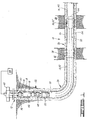
- FIG. 1 is a schematic elevation sectioned view of a well having a substantially deviated well portion and with one embodiment of completion tool of the present invention placed in the casing string.
- FIGS. 2A-2F show a cross-sectional view of the embodiment of completion tool of the present invention.
- FIG. 3 shows a lower portion of another embodiment of completion tool of the present invention.
- Referring now to the drawings, and more particularly to FIG. 1, the full opening completion tool of the present invention is shown and generally designated by the
numeral 10.Completion tool 10 is disposed in awell 12. Well 12 is constructed by placing acasing string 14 in awellbore 16 and cementing the same in place with cement as indicated bynumeral 18.Completion tool 10 forms a portion ofcasing string 14.Casing string 14 defines acasing bore 20 therethrough. -
Well 12 has a substantiallyvertical portion 22, aradiused portion 24, and a substantially non-vertical deviatedportion 26. In FIG. 1, deviatedportion 26 is illustrated as being a substantiallyhorizontal well portion 26, but the invention is not intended to be limited in such awell 14. Although the tools described herein are designed to be especially useful in the deviated portion of the well, they can, of course, also be used in the vertical portion of the well or in a wholly vertical well. -
Completion tool 10 comprises a plurality of casing valves, such as a pair ofcasing valves well portion 26 of well 14.Casing valves zones - In a preferred embodiment,
casing valves swivel connection 36. However, a more conventional, non-locking swivel connection may also be used. Also,casing valves - In FIG. 1, a
tubing string 38 having a plurality of tools connected to the lower end thereof is shown as being lowered intowell casing 14. As will be further discussed,tubing string 38 and the tools therein are used in conjunction withcompletion tool 10. - A well annulus 40 is defined between
tubing string 38 andcasing string 14. Ablowout preventer 42 located at the surface is provided to close well annulus 40. Apump 44 is connected totubing string 38 for pumping fluid downtubing string 38. -
Tubing string 38 shown in FIG. 1 has apositioner tool apparatus 46, ajetting tool apparatus 48, and may also have awash tool apparatus 50 connected thereto. - Referring now to FIGS. 2A-2F, the details of one embodiment of
completion tool 10 will be discussed. -
Completion tool 10 is connected to an upper portion 52 ofcasing string 14. In the illustrated embodiment, casingvalve 28 ofcompletion tool 10, shown in FIGS. 2A-2C, comprises anupper body 54 which forms a threadedconnection 56 with upper portion 52 ofcasing string 14.Upper body 54 is attached to the upper end of an outer housing orcase 58.Housing 58 defines alongitudinal passageway 60 therethrough and has aside wall 62 with a plurality ofhousing communication ports 64 defined through the side wall. Preferably, but not by way of limitation, there are twoports 64 spaced 180° apart. - A
lower body 66 is attached to the lower end ofhousing 50.Lower body 66 has an internal straight thread 68 for connection to lockingswivel connection 36 as will be further described herein. - Casing
valve 28 also comprises a slidingsleeve 70 which includes a collet sleeve 72 attached to a seal sleeve 74 at threadedconnection 76.Sleeve 70 is disposed inlongitudinal passageway 60 ofhousing 58 and is selectively movable relative tohousing 58 between a first position shown in FIGS. 2A-2C blocking or coveringhousing communication ports 64 and a second position whereinhousing communication ports 64 are uncovered and are communicated withlongitudinal passageway 60. - Casing
valve 28 also includes anupper wiper 78 which provides wiping engagement between collet sleeve 72 andhousing 58. Casingvalve 28 further includes spacedlower seals housing 58. In the first position ofsleeve 70, it will be seen that seals 80 and 82 are on longitudinally opposite sides ofhousing communication ports 64, thus sealingly separatingports 64 fromlongitudinal passageway 60. - A position latching means 84 is provided for releasably
latching sliding sleeve 70 in its first and second positions. Position latching means 84 is disposed in anannulus 86 defined between slidingsleeve 70 andhousing 58. It will be seen thatannulus 86 is protected betweenupper wiper 78 andseal 80. - Position latching means 84 includes a
spring collet 88, which may also be referred to as a spring biased latching means 88.Spring collet 88 is longitudinally positioned betweenupper end 90 of seal sleeve 74 of slidingsleeve 70 and downwardly facingshoulder 92 on collet sleeve 72 of slidingsleeve 70. Thus,collet 88 moves longitudinally with slidingsleeve 70 and may be considered to be attached thereto. - Position latching means 84 also includes first and second radially inwardly facing, longitudinally spaced
grooves housing 58 and corresponding to first and second positions, relatively, of slidingsleeve 70. - By placing
spring collet 88 inannulus 86, the collet is protected in that cement, sand and the like are prevented from packing around the collet and impeding its successful operation. - It is noted that position latching means 84 could also be constructed by providing a spring latch attached to
housing 58 and providing first and second grooves in slidingsleeve 70 rather than vice versa as they have been illustrated. - Sliding
sleeve 70 has a longitudinal sleeve bore 98 defined therethrough. Collet sleeve 72 of slidingsleeve 70 defines first and second inwardly facinggrooves first groove 100 andsecond groove 102 are separated by a ring orshoulder portion 104. First andsecond grooves ring 104 therebetween form a latch profile adapted for engagement by positioningtool 46 in a manner such as described in co-pending U. S. Patent Application Serial No. 07/781,701, a copy of which is incorporated herein by reference. - Sliding
sleeve 70 has alower end 106 which is the lower end of seal sleeve 74. In the illustrated embodiment, end 106 is positioned adjacent tolower body 66 and belowhousing communication port 64 when slidingsleeve 70 is in the first position shown. - Referring now to FIGS. 2C and 2D, locking
swivel connection 36 will be described.Swivel 36 comprises a casing pup joint ormandrel 108 having an externalstraight thread 110 and an external taperedthread 112 at the upper and lower ends thereof, respectively.Straight thread 110 is engaged with thread 68 inlower body 66 ofcasing valve 28. A sealing means, such asseal 114, provides sealing engagement between pup joint 108 andlower body 66. - A locking
nut 116 is positioned around pup joint 108 and adjacent tolower end 118 oflower body 66 ofcasing valve 28. Lockingnut 116 has an internalstraight thread 120 which is also threadingly engaged withexternal thread 110 on pup joint 108. - The lower end of pup joint 108 is connected to casing
valve 30 by the threaded engagement of external taperedthread 112 with internal taperedthread 122 in anupper body 124 ofcasing valve 30. - While pup joint 108 is shown as being directly connected to
lower casing valve 30, it should be understood that the pup joint may be connected to the lower casing valve by one or more casing collars. That is, upper andlower casing valves - Similar to casing
valve 28,upper body 124 ofcasing valve 30 is attached to an outer housing orcase 130.Housing 130 has alongitudinal passageway 132 defined therethrough and aside wall 134 with a plurality ofhousing communication ports 136 defined through the side wall. See FIGS. 2D-2F. - A
lower body 138 is attached to the lower end ofhousing 130.Lower body 138 has anexternal thread 140 for connection to alower portion 142 ofcasing string 14. -
Outer housing 130 ofcasing valve 30 is almost identical toouter housing 58 ofcasing valve 28, except thathousing 130 also has at least one threadedhole 144 defined therein, as seen in FIG. 2F.Hole 144 is aligned in an axial direction with one ofhousing communication ports 136. - A
radioactive insert 146 is disposed in threadedhole 144 and held in place by a threadedplug 148. The material from which insert 146 is made provides a radioactive tracer or source used to position casingvalve 30, and thuscompletion tool 10, as will be further described herein. - The internal components of
casing valve 30 are substantially identical to those ofcasing valve 28. That is, casingvalve 30 also includes a slidingsleeve 70 withseals - Referring now to FIG. 3, the lower end of an alternate lower casing valve 30' is shown. Casing 30' has an outer housing or case 130' defining a plurality of
housing communication ports 150 therein. At least one ofhousing communication ports 150 is threaded in a threadedradioactive insert 152 and is installed in the threadedhousing communication port 150 and thus is aligned with the port. In one preferred embodiment, threadedradioactive insert 152 is made of a frangible material which will fracture readily when subjected to fluid discharged from a jetting tool, as further described herein. -
Completion tool 10 preferably is made up so thathousing communication ports 64 incasing valve 28 are aligned in an axial direction withhousing communication ports 136 ofcasing valve 30 orhousing communication ports 150 of casing valve 30'. That is, eachhousing communication port 64 is longitudinally aligned with a correspondinghousing communication port -
Completion tool 10 may be made up in a conventional manner with a normal casing joint betweencasing valves ports 64 are substantially aligned withports casing joints swivel connection 36 in which pup joint 108 is threaded intolower body 66 ofcasing valve 28 and intoupper body 124 ofcasing valve 30 or 30'. Because of the straight threads, the casing valves may be rotated easily with respect to pup joint 108 to align the housing communication ports. When the ports are aligned, lockingnut 116 is threaded upwardly onexternal thread 110 oflower body 66 of casing valve 128 until the locking nut lockingly jams againstlower end 118 oflower body 66, thereby preventing further relative rotation betweencasing valve 28 and pup joint 108. -
Completion tool 10 as part ofcasing string 14 is run intoborehole 16 in a conventional manner until the casing valves are positioned adjacent to the zones of interest, such aszones - A radioactive detection means, such as a rotational gamma
ray detector apparatus 154, may be run down intocasing 14 by any means, such as atubing string 156. One such gamma ray detector is the Halliburton HLS RotaScan tool, but the invention is not intended to be limited to this particular device.Detector apparatus 154 is used to determine the position ofradioactive insert casing valve 30 andcompletion tool 10. - By prior knowledge of the plane of orientation of the fracture by use of existing well logs, or stress data,
casing string 114 may be rotated at the surface to orient radioactive insert 146 (or 152) with the fracture. It will thus be seen thathousing communication ports 64 and 136 (or 150) are thereby aligned with the fracture as well. - After completion tool 10 (or 10') with
casing valves 28 and 30 (or 30'), is positioned as desired, it may be cemented in place as shown in FIG. 1. However, it should be understood that the invention is not necessarily limited to acasing string 14 which is cemented in place.Completion tool 10 may also be used in uncemented completions wherein zonal isolation between the casing valves is established by external casing packers or the like. Also, the casing valves may be used in any cemented/uncemented combination. - After cementing of
casing string 14, the next trip into the well is withtubing string 38 includingpositioner tool 46, jettingtool 48 andwash tool 50, as schematically illustrated in FIG. 1. In FIG. 1, this tool assembly is shown as it is being lowered intovertical portion 22 ofwell 12. The tool assembly will pass through radiusedportion 24 and intonon-vertical portion 26 ofwell 12. The tool assembly should first be run to just below lowermost casing valve 30 (or 30'). - Then, hydraulic jetting begins, utilizing a filtered clear completion fluid. Hydraulic jetting is performed with jetting
tool 48 by pumping fluid downtubing string 38 and out the jetting nozzles in the jetting tool to impinge casing bore 20. Jettingtool 48 is moved upwardly throughcasing valve 30 or 30' to remove any residual cement from all of the recesses in the internal portion ofcasing valve 30 or 30'. This is particularly important when casingvalve 30 or 30' is located in a deviated well portion because significant amounts of cement may be present along the lower inside surfaces of the casing valve. The cement must be removed to insure proper engagement ofpositioning tool 46 withsleeve 70. - It is noted that when the terms "upward" or "downward" are used in the context of direction of movement in the well, these terms are used to mean movement along the axis of the well either uphole or downhole, respectively, which in many cases may not be exactly vertical and can in fact be horizontal in a horizontally oriented portion of the well.
- After hydraulically jetting the internal portion of
casing valve 30 or 30',positioning tool 46 is lowered back throughcasing valve 30 or 30' and used to engage and actuate slidingsleeve 70 therein in a manner known in the art.Tubing string 38 is pulled upwardly to apply an upward force to slidingsleeve 70 ofcasing valve 30 or 30'.Spring collet 88 is initially in engagement withfirst groove 94 ofhousing 130 or 130', and the upward pull will compress the collet to releasefirst groove 94. Ascollet 88 compresses and releases, a decrease in upward force will be noted at the surface to evidence the beginning of the opening sequence. Slidingsleeve 70 will continue to be pulled to its full extent of travel which can be confirmed by sudden rise in weight indicator reading at the surface as the top of slidingsleeve 70 abutsupper body 124. At this point,collet 88 will engagesecond groove 96. - Jetting of
communication ports jetting tool 48 in a manner known in the art. With firstembodiment casing valve 30, the jetted fluid is discharged directly throughhousing communication ports 136 to remove any cement therefrom. With second embodiment casing valve 30', using a frangibleradioactive insert 152, jetting will fracture the insert inhousing communication port 150, thereby openinghousing communication port 150 and cleaning it out. - In still another embodiment,
radioactive insert 152 is not necessarily made of a frangible material. In such a case, at least onecommunication port 150 in housing 130' does not have aninsert 152 therein. After alignment of the radioactive insert with the fracture usingdetection apparatus 154, as previously described, casing 14 is rotated by the angular displacement betweenports 150. That is, ifports 150 are spaced 90° apart, casingstring 14 is rotated 90° so that an unpluggedhousing communication port 150 is aligned with the fracture. After opening of casing valve 30', jetting is substantially identical to that previously described. - Once jetting of
casing value 30 or 30' has been completed,positioning tool 46 is used to closesleeve 70. If desired, blowout preventer 40 can be closed and the casing can be pressure tested to confirm thatcasing valve 30 or 30' is in fact closed. - Then, the
tubing string 38 is moved upwardly tocasing valve 28, and the sequence is repeated. The only difference betweencasing valve 28 andcasing valve 30 or 30' is that casingvalve 28 does not have a radioactive insert. Again, although only twocasing valves 28 and 30 (or 30') are shown in FIG. 1, additional casing valves may be included incasing string 14. - Once all of the casing valves have been jetted out and reclosed, the work string may be pulled to the top of the liner, or to the top of
non-vertical portion 26 ofcasing 14 and backwashed. Backwashing is accomplished in a manner known in the art usingwash tool 50. - The jetting operation is used to remove cement from and adjacent to the communication ports in the casing valves for facilitating fracture initiation by easing access to the formation. In the actual fracturing operation, a mechanical positioning tool is run into the casing with a packer positioned thereabove. The mechanical positioning tool may be used to open and close the sleeves in the casing valves so that sand-laden fluid may be pumped through the communication ports into the well formation. Since the casing valves have been oriented with the fracture as previously described, there is no significant interruption in the flow path between the housing communication ports (136 in
casing valve casing valve 30', or 64 in casing valve 28) and the fracture when pumping the sand-laden fluid. This eliminates fracture tortuosity and possible screen-out and keeps pump pressures at a minimum.
Claims (10)
- A sliding sleeve casing tool apparatus for use in a casing string (14) of a well, said apparatus comprising an outer housing (58;130') having a longitudinal passageway (60) defined therethrough and having a side wall (62) with a housing communication port (64,150) defined through said side wall (62); a sliding sleeve (70) slidably disposed in said longitudinal passageway (60) and being selectively movable relative to said housing between a first position blocking said communication port (64) and a second position wherein said communication port (64) is communicated with said longitudinal passageway (60); and a radioactive insert (146;152) attached to said housing (58).
- Apparatus according to claim 1, wherein said housing (58) defines a hole (144) alignable with said housing communication port (64); and said radioactive insert (146) is disposed in said hole (144).
- Apparatus according to claim 2, further comprising a plug (148) threadingly engaged with said hole (144) for retaining said insert (146) therein.
- Apparatus according to claim 1, wherein said radioactive insert (152) is disposed in said housing communication port (150).
- Apparatus according to claim 4, wherein said radioactive insert (152) is threadingly engaged with said housing communication port (150).
- Apparatus according to any of claims 1 to 5, wherein said radioactive insert (146;152) is made of a frangible material.
- Apparatus according to claim 1, wherein said housing communication port (150) is one of a plurality of housing communication ports; and said radioactive insert (152) is aligned with at least one of said housing communication ports (150).
- A completion tool apparatus for use in a casing string of a well, which apparatus comprises a sliding sleeve apparatus as claimed in any of claims 1 to 7.
- Apparatus according to claim 8, which comprises two sliding sleeve apparatus, at least one being as claimed in any of claims 1 to 7.
- Apparatus according to claim 9, wherein the casing valve is as claimed in any of claims 1 to 7.
Applications Claiming Priority (2)
| Application Number | Priority Date | Filing Date | Title |
|---|---|---|---|
| US08/080,610 US5394941A (en) | 1993-06-21 | 1993-06-21 | Fracture oriented completion tool system |
| US80610 | 1993-06-21 |
Publications (3)
| Publication Number | Publication Date |
|---|---|
| EP0633391A2 true EP0633391A2 (en) | 1995-01-11 |
| EP0633391A3 EP0633391A3 (en) | 1995-08-09 |
| EP0633391B1 EP0633391B1 (en) | 1997-11-26 |
Family
ID=22158470
Family Applications (1)
| Application Number | Title | Priority Date | Filing Date |
|---|---|---|---|
| EP94304509A Expired - Lifetime EP0633391B1 (en) | 1993-06-21 | 1994-06-21 | Sliding sleeve casing tool |
Country Status (5)
| Country | Link |
|---|---|
| US (1) | US5394941A (en) |
| EP (1) | EP0633391B1 (en) |
| DE (1) | DE69406990T2 (en) |
| DK (1) | DK0633391T3 (en) |
| NO (1) | NO942344L (en) |
Cited By (21)
| Publication number | Priority date | Publication date | Assignee | Title |
|---|---|---|---|---|
| US6497289B1 (en) | 1998-12-07 | 2002-12-24 | Robert Lance Cook | Method of creating a casing in a borehole |
| US6575240B1 (en) * | 1998-12-07 | 2003-06-10 | Shell Oil Company | System and method for driving pipe |
| US6634431B2 (en) | 1998-11-16 | 2003-10-21 | Robert Lance Cook | Isolation of subterranean zones |
| US6712154B2 (en) | 1998-11-16 | 2004-03-30 | Enventure Global Technology | Isolation of subterranean zones |
| US6725919B2 (en) | 1998-12-07 | 2004-04-27 | Shell Oil Company | Forming a wellbore casing while simultaneously drilling a wellbore |
| US6745845B2 (en) | 1998-11-16 | 2004-06-08 | Shell Oil Company | Isolation of subterranean zones |
| US6823937B1 (en) | 1998-12-07 | 2004-11-30 | Shell Oil Company | Wellhead |
| US7100685B2 (en) * | 2000-10-02 | 2006-09-05 | Enventure Global Technology | Mono-diameter wellbore casing |
| US7546881B2 (en) | 2001-09-07 | 2009-06-16 | Enventure Global Technology, Llc | Apparatus for radially expanding and plastically deforming a tubular member |
| US7665532B2 (en) | 1998-12-07 | 2010-02-23 | Shell Oil Company | Pipeline |
| US7712522B2 (en) | 2003-09-05 | 2010-05-11 | Enventure Global Technology, Llc | Expansion cone and system |
| US7739917B2 (en) | 2002-09-20 | 2010-06-22 | Enventure Global Technology, Llc | Pipe formability evaluation for expandable tubulars |
| US7740076B2 (en) | 2002-04-12 | 2010-06-22 | Enventure Global Technology, L.L.C. | Protective sleeve for threaded connections for expandable liner hanger |
| US7775290B2 (en) | 2003-04-17 | 2010-08-17 | Enventure Global Technology, Llc | Apparatus for radially expanding and plastically deforming a tubular member |
| CN101818630A (en) * | 2010-04-28 | 2010-09-01 | 金湖富源机械有限公司 | Mechanical underbalance downhole casing valve |
| US7793721B2 (en) | 2003-03-11 | 2010-09-14 | Eventure Global Technology, Llc | Apparatus for radially expanding and plastically deforming a tubular member |
| US7819185B2 (en) | 2004-08-13 | 2010-10-26 | Enventure Global Technology, Llc | Expandable tubular |
| US7886831B2 (en) | 2003-01-22 | 2011-02-15 | Enventure Global Technology, L.L.C. | Apparatus for radially expanding and plastically deforming a tubular member |
| US7918284B2 (en) | 2002-04-15 | 2011-04-05 | Enventure Global Technology, L.L.C. | Protective sleeve for threaded connections for expandable liner hanger |
| CN103790551A (en) * | 2012-11-05 | 2014-05-14 | 中国石油集团川庆钻探工程有限公司钻采工程技术研究院 | Mechanical underground sleeve valve |
| EP2966258A1 (en) * | 2014-07-10 | 2016-01-13 | Services Petroliers Schlumberger | Depth positioning using gamma-ray correlation and downhole parameter differential |
Families Citing this family (84)
| Publication number | Priority date | Publication date | Assignee | Title |
|---|---|---|---|---|
| US6604763B1 (en) | 1998-12-07 | 2003-08-12 | Shell Oil Company | Expandable connector |
| US6557640B1 (en) | 1998-12-07 | 2003-05-06 | Shell Oil Company | Lubrication and self-cleaning system for expansion mandrel |
| US6640903B1 (en) | 1998-12-07 | 2003-11-04 | Shell Oil Company | Forming a wellbore casing while simultaneously drilling a wellbore |
| AU770359B2 (en) | 1999-02-26 | 2004-02-19 | Shell Internationale Research Maatschappij B.V. | Liner hanger |
| EG22306A (en) | 1999-11-15 | 2002-12-31 | Shell Int Research | Expanding a tubular element in a wellbore |
| US7114564B2 (en) * | 2001-04-27 | 2006-10-03 | Schlumberger Technology Corporation | Method and apparatus for orienting perforating devices |
| GB2374887B (en) | 2001-04-27 | 2003-12-17 | Schlumberger Holdings | Method and apparatus for orienting perforating devices |
| CA2412072C (en) | 2001-11-19 | 2012-06-19 | Packers Plus Energy Services Inc. | Method and apparatus for wellbore fluid treatment |
| US6834233B2 (en) * | 2002-02-08 | 2004-12-21 | University Of Houston | System and method for stress and stability related measurements in boreholes |
| US8167047B2 (en) | 2002-08-21 | 2012-05-01 | Packers Plus Energy Services Inc. | Method and apparatus for wellbore fluid treatment |
| US9682425B2 (en) | 2009-12-08 | 2017-06-20 | Baker Hughes Incorporated | Coated metallic powder and method of making the same |
| US8297364B2 (en) * | 2009-12-08 | 2012-10-30 | Baker Hughes Incorporated | Telescopic unit with dissolvable barrier |
| US8327931B2 (en) | 2009-12-08 | 2012-12-11 | Baker Hughes Incorporated | Multi-component disappearing tripping ball and method for making the same |
| US8403037B2 (en) | 2009-12-08 | 2013-03-26 | Baker Hughes Incorporated | Dissolvable tool and method |
| US9101978B2 (en) | 2002-12-08 | 2015-08-11 | Baker Hughes Incorporated | Nanomatrix powder metal compact |
| US9109429B2 (en) | 2002-12-08 | 2015-08-18 | Baker Hughes Incorporated | Engineered powder compact composite material |
| US9079246B2 (en) | 2009-12-08 | 2015-07-14 | Baker Hughes Incorporated | Method of making a nanomatrix powder metal compact |
| US20090084553A1 (en) * | 2004-12-14 | 2009-04-02 | Schlumberger Technology Corporation | Sliding sleeve valve assembly with sand screen |
| US7387165B2 (en) * | 2004-12-14 | 2008-06-17 | Schlumberger Technology Corporation | System for completing multiple well intervals |
| US8151874B2 (en) * | 2006-02-27 | 2012-04-10 | Halliburton Energy Services, Inc. | Thermal recovery of shallow bitumen through increased permeability inclusions |
| US7637317B1 (en) * | 2006-10-06 | 2009-12-29 | Alfred Lara Hernandez | Frac gate and well completion methods |
| US7814978B2 (en) | 2006-12-14 | 2010-10-19 | Halliburton Energy Services, Inc. | Casing expansion and formation compression for permeability plane orientation |
| US7665520B2 (en) * | 2006-12-22 | 2010-02-23 | Halliburton Energy Services, Inc. | Multiple bottom plugs for cementing operations |
| US7647966B2 (en) | 2007-08-01 | 2010-01-19 | Halliburton Energy Services, Inc. | Method for drainage of heavy oil reservoir via horizontal wellbore |
| US7640982B2 (en) * | 2007-08-01 | 2010-01-05 | Halliburton Energy Services, Inc. | Method of injection plane initiation in a well |
| US7640975B2 (en) * | 2007-08-01 | 2010-01-05 | Halliburton Energy Services, Inc. | Flow control for increased permeability planes in unconsolidated formations |
| US7832477B2 (en) * | 2007-12-28 | 2010-11-16 | Halliburton Energy Services, Inc. | Casing deformation and control for inclusion propagation |
| US7762333B2 (en) * | 2008-04-01 | 2010-07-27 | Packers Plus Energy Services Inc. | Hydraulically openable ported sub |
| US8757273B2 (en) | 2008-04-29 | 2014-06-24 | Packers Plus Energy Services Inc. | Downhole sub with hydraulically actuable sleeve valve |
| US8261761B2 (en) | 2009-05-07 | 2012-09-11 | Baker Hughes Incorporated | Selectively movable seat arrangement and method |
| US8074714B2 (en) * | 2009-06-17 | 2011-12-13 | Baker Hughes Incorporated | System, method and apparatus for downhole orientation probe sensor |
| US8479823B2 (en) | 2009-09-22 | 2013-07-09 | Baker Hughes Incorporated | Plug counter and method |
| US10240419B2 (en) | 2009-12-08 | 2019-03-26 | Baker Hughes, A Ge Company, Llc | Downhole flow inhibition tool and method of unplugging a seat |
| US9127515B2 (en) | 2010-10-27 | 2015-09-08 | Baker Hughes Incorporated | Nanomatrix carbon composite |
| US8573295B2 (en) | 2010-11-16 | 2013-11-05 | Baker Hughes Incorporated | Plug and method of unplugging a seat |
| US9243475B2 (en) | 2009-12-08 | 2016-01-26 | Baker Hughes Incorporated | Extruded powder metal compact |
| US8425651B2 (en) | 2010-07-30 | 2013-04-23 | Baker Hughes Incorporated | Nanomatrix metal composite |
| US9227243B2 (en) | 2009-12-08 | 2016-01-05 | Baker Hughes Incorporated | Method of making a powder metal compact |
| US8528633B2 (en) | 2009-12-08 | 2013-09-10 | Baker Hughes Incorporated | Dissolvable tool and method |
| US20110187062A1 (en) * | 2010-01-29 | 2011-08-04 | Baker Hughes Incorporated | Collet system |
| US8424610B2 (en) | 2010-03-05 | 2013-04-23 | Baker Hughes Incorporated | Flow control arrangement and method |
| US9279311B2 (en) | 2010-03-23 | 2016-03-08 | Baker Hughes Incorporation | System, assembly and method for port control |
| WO2011146866A2 (en) | 2010-05-21 | 2011-11-24 | Schlumberger Canada Limited | Method and apparatus for deploying and using self-locating downhole devices |
| US8776884B2 (en) | 2010-08-09 | 2014-07-15 | Baker Hughes Incorporated | Formation treatment system and method |
| US8789600B2 (en) | 2010-08-24 | 2014-07-29 | Baker Hughes Incorporated | Fracing system and method |
| US9090955B2 (en) | 2010-10-27 | 2015-07-28 | Baker Hughes Incorporated | Nanomatrix powder metal composite |
| US9080098B2 (en) | 2011-04-28 | 2015-07-14 | Baker Hughes Incorporated | Functionally gradient composite article |
| US8631876B2 (en) | 2011-04-28 | 2014-01-21 | Baker Hughes Incorporated | Method of making and using a functionally gradient composite tool |
| US9139928B2 (en) | 2011-06-17 | 2015-09-22 | Baker Hughes Incorporated | Corrodible downhole article and method of removing the article from downhole environment |
| US9707739B2 (en) | 2011-07-22 | 2017-07-18 | Baker Hughes Incorporated | Intermetallic metallic composite, method of manufacture thereof and articles comprising the same |
| US8783365B2 (en) | 2011-07-28 | 2014-07-22 | Baker Hughes Incorporated | Selective hydraulic fracturing tool and method thereof |
| US9643250B2 (en) | 2011-07-29 | 2017-05-09 | Baker Hughes Incorporated | Method of controlling the corrosion rate of alloy particles, alloy particle with controlled corrosion rate, and articles comprising the particle |
| US9833838B2 (en) | 2011-07-29 | 2017-12-05 | Baker Hughes, A Ge Company, Llc | Method of controlling the corrosion rate of alloy particles, alloy particle with controlled corrosion rate, and articles comprising the particle |
| US9057242B2 (en) | 2011-08-05 | 2015-06-16 | Baker Hughes Incorporated | Method of controlling corrosion rate in downhole article, and downhole article having controlled corrosion rate |
| US9033055B2 (en) | 2011-08-17 | 2015-05-19 | Baker Hughes Incorporated | Selectively degradable passage restriction and method |
| US9109269B2 (en) | 2011-08-30 | 2015-08-18 | Baker Hughes Incorporated | Magnesium alloy powder metal compact |
| US9856547B2 (en) | 2011-08-30 | 2018-01-02 | Bakers Hughes, A Ge Company, Llc | Nanostructured powder metal compact |
| US9090956B2 (en) | 2011-08-30 | 2015-07-28 | Baker Hughes Incorporated | Aluminum alloy powder metal compact |
| US9643144B2 (en) | 2011-09-02 | 2017-05-09 | Baker Hughes Incorporated | Method to generate and disperse nanostructures in a composite material |
| US9347119B2 (en) | 2011-09-03 | 2016-05-24 | Baker Hughes Incorporated | Degradable high shock impedance material |
| US9133695B2 (en) | 2011-09-03 | 2015-09-15 | Baker Hughes Incorporated | Degradable shaped charge and perforating gun system |
| US9187990B2 (en) | 2011-09-03 | 2015-11-17 | Baker Hughes Incorporated | Method of using a degradable shaped charge and perforating gun system |
| US8955585B2 (en) | 2011-09-27 | 2015-02-17 | Halliburton Energy Services, Inc. | Forming inclusions in selected azimuthal orientations from a casing section |
| US8967255B2 (en) | 2011-11-04 | 2015-03-03 | Halliburton Energy Services, Inc. | Subsurface release cementing plug |
| US9238953B2 (en) | 2011-11-08 | 2016-01-19 | Schlumberger Technology Corporation | Completion method for stimulation of multiple intervals |
| US9284812B2 (en) | 2011-11-21 | 2016-03-15 | Baker Hughes Incorporated | System for increasing swelling efficiency |
| US9010416B2 (en) | 2012-01-25 | 2015-04-21 | Baker Hughes Incorporated | Tubular anchoring system and a seat for use in the same |
| US9068428B2 (en) | 2012-02-13 | 2015-06-30 | Baker Hughes Incorporated | Selectively corrodible downhole article and method of use |
| US8826980B2 (en) | 2012-03-29 | 2014-09-09 | Halliburton Energy Services, Inc. | Activation-indicating wellbore stimulation assemblies and methods of using the same |
| US9605508B2 (en) | 2012-05-08 | 2017-03-28 | Baker Hughes Incorporated | Disintegrable and conformable metallic seal, and method of making the same |
| US9650851B2 (en) | 2012-06-18 | 2017-05-16 | Schlumberger Technology Corporation | Autonomous untethered well object |
| US9234408B2 (en) * | 2013-02-21 | 2016-01-12 | Halliburton Energy Services, Inc. | Systems and methods for optimized well creation in a shale formation |
| US9631468B2 (en) | 2013-09-03 | 2017-04-25 | Schlumberger Technology Corporation | Well treatment |
| US9816339B2 (en) | 2013-09-03 | 2017-11-14 | Baker Hughes, A Ge Company, Llc | Plug reception assembly and method of reducing restriction in a borehole |
| US11167343B2 (en) | 2014-02-21 | 2021-11-09 | Terves, Llc | Galvanically-active in situ formed particles for controlled rate dissolving tools |
| WO2015127174A1 (en) | 2014-02-21 | 2015-08-27 | Terves, Inc. | Fluid activated disintegrating metal system |
| US9910026B2 (en) | 2015-01-21 | 2018-03-06 | Baker Hughes, A Ge Company, Llc | High temperature tracers for downhole detection of produced water |
| US10378303B2 (en) | 2015-03-05 | 2019-08-13 | Baker Hughes, A Ge Company, Llc | Downhole tool and method of forming the same |
| US10221637B2 (en) | 2015-08-11 | 2019-03-05 | Baker Hughes, A Ge Company, Llc | Methods of manufacturing dissolvable tools via liquid-solid state molding |
| US10016810B2 (en) | 2015-12-14 | 2018-07-10 | Baker Hughes, A Ge Company, Llc | Methods of manufacturing degradable tools using a galvanic carrier and tools manufactured thereof |
| EP3181810B1 (en) | 2015-12-18 | 2022-03-23 | Services Pétroliers Schlumberger | Distribution of radioactive tags around or along well for detection thereof |
| CA3012511A1 (en) | 2017-07-27 | 2019-01-27 | Terves Inc. | Degradable metal matrix composite |
| US11414965B2 (en) | 2018-02-27 | 2022-08-16 | Schlumberger Technology Corporation | Rotating loading tube and angled shaped charges for oriented perforating |
| EP3983645A4 (en) * | 2019-06-13 | 2023-03-01 | Services Pétroliers Schlumberger | Cementing and sand control system and methodology |
Citations (2)
| Publication number | Priority date | Publication date | Assignee | Title |
|---|---|---|---|---|
| US3291208A (en) * | 1960-12-19 | 1966-12-13 | Exxon Production Research Co | Depth control in well operations |
| US4991654A (en) * | 1989-11-08 | 1991-02-12 | Halliburton Company | Casing valve |
Family Cites Families (12)
| Publication number | Priority date | Publication date | Assignee | Title |
|---|---|---|---|---|
| US2414997A (en) * | 1944-08-18 | 1947-01-28 | Earle R Atkins Company | Swivel joint assembly |
| US3653435A (en) * | 1970-08-14 | 1972-04-04 | Exxon Production Research Co | Multi-string tubingless completion technique |
| GB2128719B (en) * | 1982-10-20 | 1986-11-26 | Vann Inc Geo | Gravity oriented perforating gun for use in slanted boreholes |
| US4523649A (en) * | 1983-05-25 | 1985-06-18 | Baker Oil Tools, Inc. | Rotational alignment method and apparatus for tubing conveyed perforating guns |
| US4542648A (en) * | 1983-12-29 | 1985-09-24 | Shell Oil Company | Method of correlating a core sample with its original position in a borehole |
| US4529036A (en) * | 1984-08-16 | 1985-07-16 | Halliburton Co | Method of determining subterranean formation fracture orientation |
| US4673890A (en) * | 1986-06-18 | 1987-06-16 | Halliburton Company | Well bore measurement tool |
| US4830120A (en) * | 1988-06-06 | 1989-05-16 | Baker Hughes Incorporated | Methods and apparatus for perforating a deviated casing in a subterranean well |
| US4926940A (en) * | 1988-09-06 | 1990-05-22 | Mobil Oil Corporation | Method for monitoring the hydraulic fracturing of a subsurface formation |
| US4979561A (en) * | 1989-11-08 | 1990-12-25 | Halliburton Company | Positioning tool |
| US4949788A (en) * | 1989-11-08 | 1990-08-21 | Halliburton Company | Well completions using casing valves |
| US5259466A (en) * | 1992-06-11 | 1993-11-09 | Halliburton Company | Method and apparatus for orienting a perforating string |
-
1993
- 1993-06-21 US US08/080,610 patent/US5394941A/en not_active Expired - Fee Related
-
1994
- 1994-06-20 NO NO942344A patent/NO942344L/en unknown
- 1994-06-21 DE DE69406990T patent/DE69406990T2/en not_active Expired - Fee Related
- 1994-06-21 DK DK94304509.6T patent/DK0633391T3/en active
- 1994-06-21 EP EP94304509A patent/EP0633391B1/en not_active Expired - Lifetime
Patent Citations (2)
| Publication number | Priority date | Publication date | Assignee | Title |
|---|---|---|---|---|
| US3291208A (en) * | 1960-12-19 | 1966-12-13 | Exxon Production Research Co | Depth control in well operations |
| US4991654A (en) * | 1989-11-08 | 1991-02-12 | Halliburton Company | Casing valve |
Cited By (26)
| Publication number | Priority date | Publication date | Assignee | Title |
|---|---|---|---|---|
| US6712154B2 (en) | 1998-11-16 | 2004-03-30 | Enventure Global Technology | Isolation of subterranean zones |
| US6745845B2 (en) | 1998-11-16 | 2004-06-08 | Shell Oil Company | Isolation of subterranean zones |
| US6634431B2 (en) | 1998-11-16 | 2003-10-21 | Robert Lance Cook | Isolation of subterranean zones |
| US6823937B1 (en) | 1998-12-07 | 2004-11-30 | Shell Oil Company | Wellhead |
| US7665532B2 (en) | 1998-12-07 | 2010-02-23 | Shell Oil Company | Pipeline |
| US6739392B2 (en) | 1998-12-07 | 2004-05-25 | Shell Oil Company | Forming a wellbore casing while simultaneously drilling a wellbore |
| US6575240B1 (en) * | 1998-12-07 | 2003-06-10 | Shell Oil Company | System and method for driving pipe |
| US6758278B2 (en) | 1998-12-07 | 2004-07-06 | Shell Oil Company | Forming a wellbore casing while simultaneously drilling a wellbore |
| US6497289B1 (en) | 1998-12-07 | 2002-12-24 | Robert Lance Cook | Method of creating a casing in a borehole |
| US6725919B2 (en) | 1998-12-07 | 2004-04-27 | Shell Oil Company | Forming a wellbore casing while simultaneously drilling a wellbore |
| US7100685B2 (en) * | 2000-10-02 | 2006-09-05 | Enventure Global Technology | Mono-diameter wellbore casing |
| US7546881B2 (en) | 2001-09-07 | 2009-06-16 | Enventure Global Technology, Llc | Apparatus for radially expanding and plastically deforming a tubular member |
| US7740076B2 (en) | 2002-04-12 | 2010-06-22 | Enventure Global Technology, L.L.C. | Protective sleeve for threaded connections for expandable liner hanger |
| US7918284B2 (en) | 2002-04-15 | 2011-04-05 | Enventure Global Technology, L.L.C. | Protective sleeve for threaded connections for expandable liner hanger |
| US7739917B2 (en) | 2002-09-20 | 2010-06-22 | Enventure Global Technology, Llc | Pipe formability evaluation for expandable tubulars |
| US7886831B2 (en) | 2003-01-22 | 2011-02-15 | Enventure Global Technology, L.L.C. | Apparatus for radially expanding and plastically deforming a tubular member |
| US7793721B2 (en) | 2003-03-11 | 2010-09-14 | Eventure Global Technology, Llc | Apparatus for radially expanding and plastically deforming a tubular member |
| US7775290B2 (en) | 2003-04-17 | 2010-08-17 | Enventure Global Technology, Llc | Apparatus for radially expanding and plastically deforming a tubular member |
| US7712522B2 (en) | 2003-09-05 | 2010-05-11 | Enventure Global Technology, Llc | Expansion cone and system |
| US7819185B2 (en) | 2004-08-13 | 2010-10-26 | Enventure Global Technology, Llc | Expandable tubular |
| CN101818630A (en) * | 2010-04-28 | 2010-09-01 | 金湖富源机械有限公司 | Mechanical underbalance downhole casing valve |
| CN101818630B (en) * | 2010-04-28 | 2012-09-05 | 金湖富源机械有限公司 | Mechanical underbalance downhole casing valve |
| CN103790551A (en) * | 2012-11-05 | 2014-05-14 | 中国石油集团川庆钻探工程有限公司钻采工程技术研究院 | Mechanical underground sleeve valve |
| CN103790551B (en) * | 2012-11-05 | 2016-12-21 | 中国石油集团川庆钻探工程有限公司钻采工程技术研究院 | A kind of mechanical underground casing valve |
| EP2966258A1 (en) * | 2014-07-10 | 2016-01-13 | Services Petroliers Schlumberger | Depth positioning using gamma-ray correlation and downhole parameter differential |
| US11761327B2 (en) | 2014-07-10 | 2023-09-19 | Schlumberger Technology Corporation | Depth positioning using gamma-ray correlation and downhole parameter differential |
Also Published As
| Publication number | Publication date |
|---|---|
| DE69406990T2 (en) | 1998-03-26 |
| NO942344L (en) | 1994-12-22 |
| EP0633391B1 (en) | 1997-11-26 |
| EP0633391A3 (en) | 1995-08-09 |
| NO942344D0 (en) | 1994-06-20 |
| DK0633391T3 (en) | 1998-02-02 |
| US5394941A (en) | 1995-03-07 |
| DE69406990D1 (en) | 1998-01-08 |
Similar Documents
| Publication | Publication Date | Title |
|---|---|---|
| EP0633391B1 (en) | Sliding sleeve casing tool | |
| US6474419B2 (en) | Packer with equalizing valve and method of use | |
| CA2017640C (en) | Well completions | |
| EP0383494B1 (en) | Retrievable bridge plug and packer apparatus | |
| US5029644A (en) | Jetting tool | |
| US5738171A (en) | Well cementing inflation packer tools and methods | |
| AU632860B2 (en) | Wash tool | |
| US5464062A (en) | Metal-to-metal sealable port | |
| US8397820B2 (en) | Method and apparatus for wellbore fluid treatment | |
| US7066264B2 (en) | Method and apparatus for treating a subterranean formation | |
| US10890047B2 (en) | Wellbore stage tool with redundant closing sleeves | |
| US4934459A (en) | Subterranean well anchoring apparatus | |
| CA2029529C (en) | Casing valve | |
| EP0539040A2 (en) | Downhole casing valve | |
| EP0581533A2 (en) | Stage cementer and inflation packer apparatus | |
| US4570714A (en) | Gravel pack assembly | |
| US6182766B1 (en) | Drill string diverter apparatus and method | |
| EP0121566A1 (en) | Retrievable inside blowout preventer valve apparatus. | |
| US5330000A (en) | Squeeze packer latch | |
| US6202742B1 (en) | Pack-off device for use in a wellbore having a packer assembly located therein | |
| CA2276522C (en) | Drill string diverter apparatus and method | |
| US4834176A (en) | Well valve | |
| CA2723012C (en) | Apparatus and method for drilling a wellbore with casing and cementing the casing in the wellbore | |
| CA2342657C (en) | Zero drill completion and production system | |
| NO20231046A1 (en) | Open hole multi-zone single trip completion system |
Legal Events
| Date | Code | Title | Description |
|---|---|---|---|
| PUAI | Public reference made under article 153(3) epc to a published international application that has entered the european phase |
Free format text: ORIGINAL CODE: 0009012 |
|
| AK | Designated contracting states |
Kind code of ref document: A2 Designated state(s): DE DK ES FR GB IT NL |
|
| PUAL | Search report despatched |
Free format text: ORIGINAL CODE: 0009013 |
|
| AK | Designated contracting states |
Kind code of ref document: A3 Designated state(s): DE DK ES FR GB IT NL |
|
| 17P | Request for examination filed |
Effective date: 19951227 |
|
| GRAG | Despatch of communication of intention to grant |
Free format text: ORIGINAL CODE: EPIDOS AGRA |
|
| 17Q | First examination report despatched |
Effective date: 19970120 |
|
| GRAH | Despatch of communication of intention to grant a patent |
Free format text: ORIGINAL CODE: EPIDOS IGRA |
|
| RAP1 | Party data changed (applicant data changed or rights of an application transferred) |
Owner name: HALLIBURTON ENERGY SERVICES, INC. |
|
| GRAH | Despatch of communication of intention to grant a patent |
Free format text: ORIGINAL CODE: EPIDOS IGRA |
|
| GRAA | (expected) grant |
Free format text: ORIGINAL CODE: 0009210 |
|
| ITF | It: translation for a ep patent filed |
Owner name: BARZANO' E ZANARDO MILANO S.P.A. |
|
| AK | Designated contracting states |
Kind code of ref document: B1 Designated state(s): DE DK ES FR GB IT NL |
|
| PG25 | Lapsed in a contracting state [announced via postgrant information from national office to epo] |
Ref country code: ES Free format text: THE PATENT HAS BEEN ANNULLED BY A DECISION OF A NATIONAL AUTHORITY Effective date: 19971126 |
|
| REF | Corresponds to: |
Ref document number: 69406990 Country of ref document: DE Date of ref document: 19980108 |
|
| ET | Fr: translation filed | ||
| REG | Reference to a national code |
Ref country code: DK Ref legal event code: T3 |
|
| PLBE | No opposition filed within time limit |
Free format text: ORIGINAL CODE: 0009261 |
|
| STAA | Information on the status of an ep patent application or granted ep patent |
Free format text: STATUS: NO OPPOSITION FILED WITHIN TIME LIMIT |
|
| 26N | No opposition filed | ||
| PGFP | Annual fee paid to national office [announced via postgrant information from national office to epo] |
Ref country code: FR Payment date: 19990610 Year of fee payment: 6 |
|
| PGFP | Annual fee paid to national office [announced via postgrant information from national office to epo] |
Ref country code: DK Payment date: 19990614 Year of fee payment: 6 |
|
| PGFP | Annual fee paid to national office [announced via postgrant information from national office to epo] |
Ref country code: GB Payment date: 19990616 Year of fee payment: 6 |
|
| PGFP | Annual fee paid to national office [announced via postgrant information from national office to epo] |
Ref country code: DE Payment date: 19990618 Year of fee payment: 6 |
|
| PGFP | Annual fee paid to national office [announced via postgrant information from national office to epo] |
Ref country code: NL Payment date: 19990628 Year of fee payment: 6 |
|
| PG25 | Lapsed in a contracting state [announced via postgrant information from national office to epo] |
Ref country code: GB Free format text: LAPSE BECAUSE OF NON-PAYMENT OF DUE FEES Effective date: 20000621 Ref country code: DK Free format text: LAPSE BECAUSE OF NON-PAYMENT OF DUE FEES Effective date: 20000621 |
|
| PG25 | Lapsed in a contracting state [announced via postgrant information from national office to epo] |
Ref country code: NL Free format text: LAPSE BECAUSE OF NON-PAYMENT OF DUE FEES Effective date: 20010101 |
|
| REG | Reference to a national code |
Ref country code: DK Ref legal event code: EBP |
|
| GBPC | Gb: european patent ceased through non-payment of renewal fee |
Effective date: 20000621 |
|
| PG25 | Lapsed in a contracting state [announced via postgrant information from national office to epo] |
Ref country code: FR Free format text: LAPSE BECAUSE OF NON-PAYMENT OF DUE FEES Effective date: 20010228 |
|
| NLV4 | Nl: lapsed or anulled due to non-payment of the annual fee |
Effective date: 20010101 |
|
| REG | Reference to a national code |
Ref country code: FR Ref legal event code: ST |
|
| PG25 | Lapsed in a contracting state [announced via postgrant information from national office to epo] |
Ref country code: DE Free format text: LAPSE BECAUSE OF NON-PAYMENT OF DUE FEES Effective date: 20010403 |
|
| PG25 | Lapsed in a contracting state [announced via postgrant information from national office to epo] |
Ref country code: IT Free format text: LAPSE BECAUSE OF NON-PAYMENT OF DUE FEES Effective date: 20050621 |