EP0630154A2 - Television receiver capable of enlarging and compressing image - Google Patents
Television receiver capable of enlarging and compressing image Download PDFInfo
- Publication number
- EP0630154A2 EP0630154A2 EP94109332A EP94109332A EP0630154A2 EP 0630154 A2 EP0630154 A2 EP 0630154A2 EP 94109332 A EP94109332 A EP 94109332A EP 94109332 A EP94109332 A EP 94109332A EP 0630154 A2 EP0630154 A2 EP 0630154A2
- Authority
- EP
- European Patent Office
- Prior art keywords
- signal
- output
- vertical
- memory
- image
- Prior art date
- Legal status (The legal status is an assumption and is not a legal conclusion. Google has not performed a legal analysis and makes no representation as to the accuracy of the status listed.)
- Granted
Links
Images


Classifications
-
- H—ELECTRICITY
- H04—ELECTRIC COMMUNICATION TECHNIQUE
- H04N—PICTORIAL COMMUNICATION, e.g. TELEVISION
- H04N7/00—Television systems
- H04N7/01—Conversion of standards, e.g. involving analogue television standards or digital television standards processed at pixel level
- H04N7/0117—Conversion of standards, e.g. involving analogue television standards or digital television standards processed at pixel level involving conversion of the spatial resolution of the incoming video signal
- H04N7/0122—Conversion of standards, e.g. involving analogue television standards or digital television standards processed at pixel level involving conversion of the spatial resolution of the incoming video signal the input and the output signals having different aspect ratios
-
- H—ELECTRICITY
- H04—ELECTRIC COMMUNICATION TECHNIQUE
- H04N—PICTORIAL COMMUNICATION, e.g. TELEVISION
- H04N3/00—Scanning details of television systems; Combination thereof with generation of supply voltages
- H04N3/10—Scanning details of television systems; Combination thereof with generation of supply voltages by means not exclusively optical-mechanical
- H04N3/16—Scanning details of television systems; Combination thereof with generation of supply voltages by means not exclusively optical-mechanical by deflecting electron beam in cathode-ray tube, e.g. scanning corrections
- H04N3/27—Circuits special to multi-standard receivers
Definitions
- the present invention relates to a digital processing of video signal and in particular to an image compressing and enlarging circuitry which is capable of displaying an image on a screen without giving disparity feeling by compressing and enlarging an image to a desired size to match the aspect ratio of the screen of a display even if the aspect ratio of the image obtained by a video signal is different from the aspect ratio of the screen of the display.
- JP-A-1-194784 discloses a combined method including a method of adapting an image having an aspect ratio of 4:3 onto a screen having an aspect ratio of 16:9 by changing the write frequency of a line memory and the read frequency thereof to compress the image in a horizontal direction and a method of enlarging the image in a vertical direction by changing the amplitude of an output of the deflecting circuit for cutting the upper and lower areas of the image.
- JP-A-3-11891 discloses a technology for enlarging an image in a vertical direction by digital signal processing.
- the proposed circuit configuration for interpolating scanning lines using digital signal processing to enlarge the image in a vertical direction is shown in Fig. 1.
- reference numerals 201 and 202 denote input and output terminals of digitalized video signal, respectively; 203 a memory having a capacity of at least about 120 lines; 204 one-line memory; 205 and 206 ROM tables which are used for multiplying an input signal by a coefficient; 207 an adder; 208 an input terminal of a control signal for the memory 203; 209 an input terminal of a control signal for switching tables of the ROMs 205 and 206.
- the memory 203 is controlled to conduct reading of the same line plural times with a predetermined line period in accordance with a control signal from the input terminal 208.
- scanning line signals of adjacent upper and lower lines are supplied to the ROMs 205 and 206 and are multiplied by a coefficient in a ROM table which is selected by a control signal from the input terminal 209.
- a signal having a suitable center of gravity of scanning lines can be obtained from the adder 207.
- the thus obtained enlarged image provide a large size picture displayed with high quality since the spacings between scanning lines when progressive scanning signals are used are less changed in comparison with a case in which the image are enlarged by changing the amplitude of the output of the deflecting circuit.
- the above mentioned two inventions are excellent as systems for displaying an image having an aspect ratio of 4:3 on a screen having an aspect ratio of 16:9.
- letter box type image of movie software which are commonly found in recent software packages have various aspect ratios. It has become harder to change an image having various aspect ratios to an optimum size for displays having an aspect ratio of 16:9.
- an image compressing and enlarging circuit comprising memory means which can be controlled on a line-by-line basis, vertical enlargement control means for controlling the memory means to read the same line plural times with a line period corresponding to a preset magnification factor; horizontal enlargement control means for controlling the memory means to read the same pixel plural times with a pixel period corresponding to the preset magnification factor; clock generating means for generating a read clock having a frequency not less than that of a write clock from the write clock of said memory means; and combining means for combining output signals from said horizontal and vertical enlargement control means with an output signal from said clock generating means.
- the input video signal is written into said memory means in response to said write clock.
- the input video signal is managed on a line-by-line basis.
- the vertical enlargement control means determines the line period associated with reading from said memory means in accordance with a preset magnification factor by performing an operation and outputs a control signal.
- the horizontal enlargement control means determines the pixel period associated with reading from said memory means in accordance with a preset magnification factor and outputs a control signal.
- the clock generating means generates a new clock which depends on the horizontal compression factor of the image from the input write clock.
- Said combining means combines the control signals from said vertical and horizontal enlargement control means with said read clock to supply the combined signal to said memory means.
- a large magnification factor for example, 4/3 times
- the period which is taken for the vertical enlargement control means to read the same line in every four lines again on a line-by-line basis is preset to 4 lines.
- the horizontal enlargement control means controls so that the same pixel in every four pixels is read. Accordingly, a video signal which is enlarged 4/3 times in both vertical and horizontal directions will be output.
- a desired magnification factor can be obtained by changing said preset value.
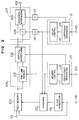
- a reference numeral 101 denotes an input terminal for digitalized video signal; 102 an output terminal for the video signal; 103 a field memory; 104 a vertical interpolating enlarging circuit; 106 a vertical interpolating circuit; 107 a horizontal interpolating enlarging circuit; 108 an image delay circuit; 109 a horizontal interpolating circuit; 110 a vertical enlarging control circuit; 111 a memory control circuit; 112 a vertical interpolation coefficient generating circuit; 113 a horizontal enlarging control circuit; 114 an image delay control circuit; 115 a horizontal interpolation coefficient generating circuit; 116 a first delay circuit; 117 a second delay circuit; 118 an input terminal for a write clock; 119 a read clock generating circuit; 120 an input terminal for a vertical enlarging ratio preset value; 121 an input terminal for a horizontal enlarging ratio presetting value
- an image signal which is input from the input terminal 101 is controlled by a write clock from the input terminal 118 on a line-by-line basis so that it is sequentially written into the field memory 103.
- the clock generating circuit 119 generates a read clock having a frequency which is about 4/3 times as high as that of the input write clock and supplies it to the field memory 103 via the combining circuit 122. Accordingly, the video signal in which an image is compressed in a horizontal direction will be read from the field memory 103.
- the vertical enlarging control circuit 110 controls the field memory 103 via the combining circuit 122 for reading the video signal from the field memory 103 with a line period corresponding to a magnification factor.
- the circuit 110 prohibits writing of the one-line memory 105 included in the vertical enlarging circuit 104 with the same period to provide a line delay output of an output signal of the field memory 103. Manner of this operation is illustrated in Fig. 3.
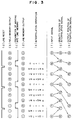
- Fig. 3 is an explanatory view showing control of a scanning line in case where the scanning line is enlarged 4/3 times in a vertical direction.
- Fig. 3(b) shows an output signal of the field memory 103.
- the same scanning line is repeatedly read in synchronization with a line reset (Fig. 3(a)) which is conducted by the memory control circuit 111.
- the output signal is provided from the one-line memory 105 (Fig. 3(d)) by prohibiting writing of one line before line reset (Fig. 3(a)) in response to a write prohibiting control signal of the one-line memory 105.
- signals for upper and lower adjacent two scanning lines are supplied to the vertical interpolating circuit 106. That is, the signals shown in Figs. 3(b) and 3(a) are necessarily signals for adjacent scanning lines.
- the vertical interpolating circuit 106 generates a scanning line signal by an interpolating operation (Fig. 3(e)) in accordance with a control signal from the vertical enlarging control circuit 110.
- a reference numeral 120 denotes an input terminal for an enlargement preset value which is determined in accordance with the magnification factor; 402 an output terminal for an interpolation coefficient; 403 an output terminal for a memory control signal; 402 an input terminal for a pulse having one line period; 405 an adder for adding the interpolation coefficient to the magnification factor preset value input from the input terminal 120; 406 a latch circuit for an output signal of the adder 405; 407 a latch circuit for a carry out signal of the adder 405.
- This circuit configuration designed for 8 bits of the output interpolation coefficient.
- a new interpolation coefficients in each line can be serially obtained by repeatedly adding the magnification factor preset value with the fed back interpolation coefficient in the adder 405 in accordance with the pulse input from the input terminal 404.
- the carry signal for the adder 405 will become a memory control signal for repeatedly reading the same line in the field memory 108.
- theoretically desired magnification factor can be obtained by increasing the bit precision.
- the scanning line will become a signal having a gravity center in a position of Fig. 3(g) relative to the input video signal shown in Fig. 3(f) (video signal input from the input terminal 101).
- a video signal representing an image which is enlarged in a vertical direction can be obtained.
- Enlargement in a horizontal direction can be achieved in the same manner as the enlargement in a vertical direction.
- a delay control signal which is generated by the horizontal enlargement control circuit 113 is fed to the field memory 103 via the combining circuit 122.
- the field memory is controlled to read the same pixel therefrom again with a period corresponding to the magnification factor in response to the delay control signal so that a video signal representing an image which is enlarged in a horizontal direction is obtained.
- the horizontal enlarging circuit 107 conducts a horizontal interpolation in accordance with a control signal from the horizontal enlargement control circuit 113 to provide a video signal representing an image which is enlarged in a horizontal direction and balanced in gravity center.
- Delay circuits 116 and 117 are inserted for adjusting the delay time between the control of the field memory 103 and the control of the pixel delay circuit 108, and the horizontal interpolation circuit 109.
- Temporal compression of an image in a horizontal direction and enlargement of an image in vertical and horizontal directions to display the image having an aspect ratio of 4:3 on a screen having an aspect ratio of 16:9 by using the field memory 103 and one-line memory 105, etc. in such a manner in the present embodiment can be conducted by a simple circuit configuration.
- a field memory HM 530281 manufactured by Hitachi Ltd. makes it possible to repeatedly read the same line by using a line reset function to provide a simple control.
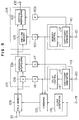
- a reference numeral 501 denotes a delay circuit for delaying a control signal for the field memory 103; 502 a delay circuit for an interpolation coefficient; the other components are identical with those of the embodiment of Fig. 2.
- the present embodiment is different from the embodiment of Fig. 2 only in that enlargement of an image in a vertical direction is conducted in a vertical direction after enlargement in a horizontal direction is conducted in the horizontal enlargement circuit 107. Operation of the circuit in the present embodiment is identical with that of the embodiment of Fig. 2.
- the delay periods of time of the delay circuits 116 and 117 are very shorter than those of the embodiment of Fig. 2.
- the scale of the circuit can be advantageously reduced.
- the delay circuits 501 and 502 are controlled on a line-by-line basis. Accordingly, necessity for delay is almost eliminated by considering the timing of the control signal generation of the vertical enlargement control circuit 110. In other words, adopting of the configuration of the present embodiment provides a circuit having a smaller scale which is capable of compressing and enlarging an image in a desired manner.
- FIG. 6 A further embodiment of the present invention is shown in Fig. 6.
- a reference numeral 601 denotes a second horizontal enlargement control circuit having the same configuration as that of the horizontal enlargement control circuit 113.
- the other components are identical with those of the embodiment of Fig. 2.
- the present embodiment is different from the embodiment of Fig. 2 in that it includes a second horizontal enlargement control circuit 601 having similar operation as well as the horizontal enlargement control circuit 113. Operation of the circuit of the present embodiment is identical with that of the embodiment of Fig. 2.
- a first enlargement control circuit 113 controls the field memory 104 in accordance with a magnification factor present value fed from an input terminal 121 to provide a video signal representing an image which is enlarged in a horizontal direction.
- a second horizontal enlargement control circuit 601 is reset with a time lag which is delayed between the field memory 103 and the horizontal interpolation enlargement circuit 107 relative to the reset timing of the first horizontal enlargement control circuit 113 to provide a delay control signal for controlling the pixel delay circuit 108 in the horizontal interpolating enlarging circuit 107 and a coefficient value for controlling the horizontal interpolating circuit 109.
- the delay circuits 116 and 117 which are necessary in the embodiment of Fig. 2 are eliminated.
- Most suitable circuit can be formed by choosing a circuit having a smaller scale from the delay circuits 116 and 117 of Fig. 2 and the second horizontal enlargement control circuit 601 in Fig. 6.
- the whole of the image can be compressed or enlarged to a desired size in both vertical and horizontal directions by the vertical enlargement control circuit 110 and the horizontal enlargement control circuit 113.
- This approach is advantageous in reduction in blanking (no signal) areas on a screen when laterally elongated image such as letter box type movie image represented by the currently available video signals are displayed on a screen of display having an aspect ratio 16:9.
- an image having a usual aspect ratio of 4:3 the area of the image which is rendered invisible on the screen by the enlargement is large.
- the right and left side areas of the image is rendered invisible by the alignment of the image with the upper and lower sides of the screen and blanking areas are formed on the upper and lower areas of the screen by the alignment of the image to the right and left sides of the screen, giving a disparity feeling. It is also reported that a sticking problem occurs on the screen.
- FIG. 7 An embodiment in which the above mentioned problems are overcome will be described with reference to Fig. 7.
- the present embodiment is different from the above mentioned embodiment in that the vertical and horizontal enlargement control circuits 110 and 113 are improved.
- Fig. 7 is a block diagram showing the configuration of the vertical enlargement control circuit 110.
- a reference numeral 701 denotes a vertical counter for counting the number of lines on the screen; 702 a numerical value converter for converting the value or count of vertical counter 701 in accordance with a predetermined function.
- the other components are identical with those in Fig. 4. Since the preset value of the magnification factor from the input terminal 120 in the embodiment of Fig. 4 can be freely converted in accordance with the presetting of the numerical value converter 702 depending upon the location on the screen, a desired area in the image can be enlarged at a desired ratio.
- the numerical value converter can be formed of logical circuits if the function is simple. For a complicated function, a look-up table system using ROMs, etc. may be adopted. An application in this embodiment is shown in Fig. 8.
- Fig. 8(A) shows an image which is represented by an video signal of the current format and is compressed in a horizontal direction and is then displayed on a screen having an aspect ratio of 16:9.
- the image of the laterally elongated letter box type and its aspect ratio is presumed about 2:1.
- the whole of the image including blanking areas prior to compression has an aspect ratio of 4:3.
- Fig. 8B shows an image of Fig. 8A which is enlarged 4/3 times in both vertical and horizontal directions.
- the size of the image in a horizontal direction is equal to that of the screen having an aspect ratio of 16:9.
- blanking areas are left on the upper and lower side of the screen in this case as mentioned above, giving a disparity feeling.
- Fig. 8C shows a function in the numerical value converter 702 shown in Fig. 7.
- Ordinate denotes a value (count) of the vertical counter 701 while abscissa denotes a magnification factor.
- This function provides a magnification factor of 4/3 in the center of the screen and in the vicinity thereof and increases the magnification factor on the upper and lower side areas of the screen and provides an average magnification factor of 3/2 in a vertical direction.
- Definition of such a function in the numerical value converter 702 provides an image which is displayed on a screen having an aspect ratio of 16:9 without blanking areas. Since the magnification factor in a horizontal direction is equal to that in a vertical direction in the central area on the screen, the image is displayed with a correct roundness. The roundness is changed only in the edges of screen. This hardly gives a disparity feeling for the image.
- Fig. 8E shows an image which is enlarged 3/2 times in both vertical and horizontal directions.
- the size of the image in a vertical direction is equal to that of the screen having an aspect ratio of 16:9. Some areas of the image in a horizontal direction are lost.
- concept of the above mentioned numerical value converter 702 is introduced to the horizontal enlargement control circuit 113.
- An input signal of the numerical value converter 702 representing the count of the horizontal counter (not shown) and a function determining the magnification factor which decreases on opposite sides of the screen in a horizontal direction will be chosen. If the average magnification factor in a horizontal direction is preset to 4/3 times, the whole of the image can be displayed on a screen having an aspect ratio of 16:9 as shown in Fig. 8G. Also in this case, the image is distorted only at the opposite side areas of the screen in a horizontal direction, giving almost no disparity feeling.
- the image can be partially compressed and enlarged by combination of the numerical value converter 702 shown in Fig. 7 with a circuit which is capable of enlarging the image shown in Fig. 2 to a desired size in the present embodiment. Accordingly, an image having an aspect ratio of 4:3 or letter box size image can be displayed on the screen having an aspect ratio of 16:9 without giving disparity feeling.
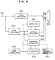
- a reference numeral 901 denotes an input terminal of video signal; 902 a display including a screen having an aspect ratio of 4:3; 903 an image processing circuit for conducting signal processing for input video signal such as Y/C separation and sending the processed signal to the display 902; 904 a synchronization processing circuit for taking a synchronization signal from a video signal; 905 a mode presetting circuit for presetting the enlargement/compression factor of the video signal; 906 a vertical deflection circuit for outputting a vertical deflecting current for driving the display 902 in accordance with a mode specified by the mode presetting circuit 905 from an output signal of the synchronization processing circuit; 906 a horizontal deflection circuit for outputting a horizontal deflecting current for driving the display 902 in accordance with a mode specified by the mode presetting circuit 905 from the output signal of the synchronization processing circuit 904; 908 and 909 first and second deflecting current correcting
- the present embodiment is different from the above mentioned embodiments in that partial compression and enlargement of image is conducted by the deflection circuits and the deflection current correcting circuit.
- the vertical deflection circuit 906 generates a vertical saw-tooth wave for driving the display 902 in accordance with a vertical deflecting pulse from the synchronization processing circuit 904.
- the horizontal deflection circuit 907 generates a horizontal saw-tooth wave for driving the display 902 in accordance with a horizontal deflecting pulse from the synchronization processing circuit 904.
- the vertical and horizontal deflection circuits 906 and 907 change the gradient and the phase of the generated saw-tooth wave. Accordingly, the whole of the image is enlarged in vertical and horizontal directions.
- the first and second deflection current correcting circuits 906 and 909 correct the operation of the vertical and horizontal deflection circuits 906 and 907, respectively to give partial distortion to the saw-tooth wave.
- This correction partially changes the gradient of the saw-tooth wave so that the image have enlargement/compression factor which changes depending upon the location on the screen.
- the present embodiment is particularly effective for displaying a letter box type image on a screen having an aspect ratio of 4:3.
- An application of the embodiment is shown in Fig. 10.
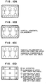
- Fig. 10A shows a letter box type image which is displayed on a screen having an aspect ratio of 4:3. Letter box type displays will be adopted in the second generation EDTV systems and are expected to become more popular. In the second generation EDTV systems, high definition information is displayed in upper and lower blanking areas on the screen, it is considered that slight artificiality remains on the screen having an aspect ratio of 4:3.
- Fig. 8B shows a scheme for reducing the blanking areas by using the vertical and horizontal deflection circuits 906 and 907 to enlarge the whole of image in vertical and horizontal directions. However, there remains a problem that an image is not invisible at the right and left side areas on the screen. Fig.
- FIG. 8C shows an image which is compressed by decreasing the gradient of the horizontal saw-tooth wave on both right and left side thereof by means of the second deflection current correcting circuit 909 is are enlarged by increasing the gradient of the saw tooth wave on the upper and lower sides thereof by means of the first deflection current correcting circuit 908. Accordingly, almost all necessary images can be displayed.
- Fig. 8D shows the distortion of the displayed image when the display method of Fig. 8C is adopted. No distortion occurs in the center area (a) of the screen and the distortion is largest at the corners (d) of the screen. It hardly matters.
- the approach of the present embodiment is also effective for the case in which an image is displayed on a screen having an aspect ratio of 16:9. This approach is comparatively more simple in comparison with the enlargement/compression factor variable approach using the above mentioned digital processing and is effective for the analog type displays.
- the whole of the image can be compressed or enlarged in order to display the image having an aspect ratio of 4:3 on a screen having a ratio of 16:9, an image which matches the aspect ratio of the screen can be obtained and the image can be displayed on the screen without giving disparity feeling.
- the invention can be embodied with a small circuit scale.
Abstract
Description
- The present invention relates to a digital processing of video signal and in particular to an image compressing and enlarging circuitry which is capable of displaying an image on a screen without giving disparity feeling by compressing and enlarging an image to a desired size to match the aspect ratio of the screen of a display even if the aspect ratio of the image obtained by a video signal is different from the aspect ratio of the screen of the display.
- Test broadcasting of high definition TV has started since 1991 in Japan and the home TV sets with a screen having an aspect ratio of 16:9 has begun to be spread. Matching of the TV sets including a screen having an aspect ratio of 16:9 with the conventional TV broad casting is a critical factor of prevailing. It is a great problem that how the aspect ratio of the image of the broadcast is changed into 16:9. If an image having movie size which is commonly found in a number of recent movie software packages, that is, so-called letter box type image (the aspect ratios of the image are various) in which the aspect ratio of the whole image is 4:3 and there are blanking areas on upper and lower sides of a screen is displayed on a display with a screen having an aspect ratio of 16:9, an aspect ratio which is approximate to 16:9 could be obtained by enlarging the image in a vertical direction. Therefore, enlargement of images in a vertical direction has become an critical technology.
- JP-A-1-194784 discloses a combined method including a method of adapting an image having an aspect ratio of 4:3 onto a screen having an aspect ratio of 16:9 by changing the write frequency of a line memory and the read frequency thereof to compress the image in a horizontal direction and a method of enlarging the image in a vertical direction by changing the amplitude of an output of the deflecting circuit for cutting the upper and lower areas of the image.
- JP-A-3-11891 discloses a technology for enlarging an image in a vertical direction by digital signal processing. The proposed circuit configuration for interpolating scanning lines using digital signal processing to enlarge the image in a vertical direction is shown in Fig. 1.
- In Fig. 1,
reference numerals memory 203; 209 an input terminal of a control signal for switching tables of theROMs - In the disclosed invention, the
memory 203 is controlled to conduct reading of the same line plural times with a predetermined line period in accordance with a control signal from theinput terminal 208. As a result of delay of a video signal by one line in the one-line memory 204, scanning line signals of adjacent upper and lower lines are supplied to theROMs input terminal 209. A signal having a suitable center of gravity of scanning lines can be obtained from theadder 207. - The thus obtained enlarged image provide a large size picture displayed with high quality since the spacings between scanning lines when progressive scanning signals are used are less changed in comparison with a case in which the image are enlarged by changing the amplitude of the output of the deflecting circuit.
- In such a manner, various techniques have been used to display an image having an aspect ratio of 4:3 on a screen having an aspect ratio of 16:9.
- The above mentioned two inventions are excellent as systems for displaying an image having an aspect ratio of 4:3 on a screen having an aspect ratio of 16:9. However, letter box type image of movie software which are commonly found in recent software packages have various aspect ratios. It has become harder to change an image having various aspect ratios to an optimum size for displays having an aspect ratio of 16:9.
- It is necessary to display a framing signal particularly in projector type displays when most image having an aspect ratio of 4:3 are compressed and displayed. A problem of sticking of screen or difference in luminescence decay of a phosphor may occur. Accordingly, a method of displaying no framing signal is required.
- It is an object of the present invention to provide an image compressing and enlarging circuit which is capable of providing an image having a size which is matched with the aspect ratio of a screen of a display by compressing and enlarging the whole of the image to a desired size.
- It is another object of the present invention to provide an image compressing and enlarging circuit which is capable of providing an image which is matched with the aspect ratio of a screen of a display by partially compressing and enlarging the image.
- The above mentioned object of the present invention is accomplished by providing an image compressing and enlarging circuit comprising memory means which can be controlled on a line-by-line basis, vertical enlargement control means for controlling the memory means to read the same line plural times with a line period corresponding to a preset magnification factor; horizontal enlargement control means for controlling the memory means to read the same pixel plural times with a pixel period corresponding to the preset magnification factor; clock generating means for generating a read clock having a frequency not less than that of a write clock from the write clock of said memory means; and combining means for combining output signals from said horizontal and vertical enlargement control means with an output signal from said clock generating means.
- The input video signal is written into said memory means in response to said write clock. At this time, the input video signal is managed on a line-by-line basis. On the other hand, the vertical enlargement control means determines the line period associated with reading from said memory means in accordance with a preset magnification factor by performing an operation and outputs a control signal. Similarly, the horizontal enlargement control means determines the pixel period associated with reading from said memory means in accordance with a preset magnification factor and outputs a control signal. The clock generating means generates a new clock which depends on the horizontal compression factor of the image from the input write clock. Said combining means combines the control signals from said vertical and horizontal enlargement control means with said read clock to supply the combined signal to said memory means.
- If an image having an aspect ratio of 4:3 is displayed on a screen having an aspect ratio of 16:9 with a correct roundness, the frequency of a new read clock is made 4/3 times as high as that of the write clock and the magnification factor is preset 1. Then, the period which is taken to read the same line again from said on a line-by-line basis and the period which is taken to read the same pixel again on a pixel-by-pixel basis would become infinitely great. This means that the read clock will have a frequency which is 4/3 times. The image will be compressed in a horizontal direction and displayed. Therefore, an image having an aspect ratio of 4:3 will be adapted on a screen having a ratio of 16:9.
- If a large magnification factor, for example, 4/3 times is preset, the period which is taken for the vertical enlargement control means to read the same line in every four lines again on a line-by-line basis is preset to 4 lines. The horizontal enlargement control means controls so that the same pixel in every four pixels is read. Accordingly, a video signal which is enlarged 4/3 times in both vertical and horizontal directions will be output. A desired magnification factor can be obtained by changing said preset value.
-
- Fig. 1 is a block diagram showing the configuration of a prior art;
- Fig. 2 is a block diagram showing an embodiment of the present invention;
- Fig. 3 is an explanatory view illustrating operation of the circuit of Fig. 1 and the principle of the image enlargement;
- Fig. 4 is a block diagram showing the configuration of a vertical enlargement control circuit of Fig. 1;
- Fig. 5 is a block diagram showing another embodiment of the present invention;
- Fig. 6 is a block diagram showing a further embodiment of the present invention;
- Fig. 7 is a block diagram showing the configuration of the vertical enlargement control circuit in a further embodiment of the present invention;
- Figs. 8A to 8G are explanatory views showing the applications of the embodiment of Fig. 7;
- Fig. 9 is a block diagram showing a further embodiment of the present invention; and
- Figs. 10A to 10D are explanatory views showing applications of the embodiment of Fig. 9.
- Now, embodiments of the present invention will be described with reference to drawings.
- Referring now to Fig. 2, there is shown an embodiment of the present invention. In Fig. 2, a reference numeral 101 denotes an input terminal for digitalized video signal; 102 an output terminal for the video signal; 103 a field memory; 104 a vertical interpolating enlarging circuit; 106 a vertical interpolating circuit; 107 a horizontal interpolating enlarging circuit; 108 an image delay circuit; 109 a horizontal interpolating circuit; 110 a vertical enlarging control circuit; 111 a memory control circuit; 112 a vertical interpolation coefficient generating circuit; 113 a horizontal enlarging control circuit; 114 an image delay control circuit; 115 a horizontal interpolation coefficient generating circuit; 116 a first delay circuit; 117 a second delay circuit; 118 an input terminal for a write clock; 119 a read clock generating circuit; 120 an input terminal for a vertical enlarging ratio preset value; 121 an input terminal for a horizontal enlarging ratio presetting value and 122 a combining circuit for a memory control signal.
- In Fig. 2, an image signal which is input from the input terminal 101 is controlled by a write clock from the
input terminal 118 on a line-by-line basis so that it is sequentially written into thefield memory 103. The clock generatingcircuit 119 generates a read clock having a frequency which is about 4/3 times as high as that of the input write clock and supplies it to thefield memory 103 via the combiningcircuit 122. Accordingly, the video signal in which an image is compressed in a horizontal direction will be read from thefield memory 103. The verticalenlarging control circuit 110 controls thefield memory 103 via the combiningcircuit 122 for reading the video signal from thefield memory 103 with a line period corresponding to a magnification factor. Thecircuit 110 prohibits writing of the one-line memory 105 included in thevertical enlarging circuit 104 with the same period to provide a line delay output of an output signal of thefield memory 103. Manner of this operation is illustrated in Fig. 3. - Fig. 3 is an explanatory view showing control of a scanning line in case where the scanning line is enlarged 4/3 times in a vertical direction.
- Fig. 3(b) shows an output signal of the
field memory 103. The same scanning line is repeatedly read in synchronization with a line reset (Fig. 3(a)) which is conducted by the memory control circuit 111. The output signal is provided from the one-line memory 105 (Fig. 3(d)) by prohibiting writing of one line before line reset (Fig. 3(a)) in response to a write prohibiting control signal of the one-line memory 105. As a result, signals for upper and lower adjacent two scanning lines are supplied to thevertical interpolating circuit 106. That is, the signals shown in Figs. 3(b) and 3(a) are necessarily signals for adjacent scanning lines. - The
vertical interpolating circuit 106 generates a scanning line signal by an interpolating operation (Fig. 3(e)) in accordance with a control signal from the vertical enlargingcontrol circuit 110. - Configuration of the vertical enlarging
control circuit 110 is shown in Fig. 4. In Fig. 5, areference numeral 120 denotes an input terminal for an enlargement preset value which is determined in accordance with the magnification factor; 402 an output terminal for an interpolation coefficient; 403 an output terminal for a memory control signal; 402 an input terminal for a pulse having one line period; 405 an adder for adding the interpolation coefficient to the magnification factor preset value input from theinput terminal 120; 406 a latch circuit for an output signal of theadder 405; 407 a latch circuit for a carry out signal of theadder 405. - This circuit configuration designed for 8 bits of the output interpolation coefficient. A new interpolation coefficients in each line can be serially obtained by repeatedly adding the magnification factor preset value with the fed back interpolation coefficient in the
adder 405 in accordance with the pulse input from theinput terminal 404. At this time, the carry signal for theadder 405 will become a memory control signal for repeatedly reading the same line in thefield memory 108. In case of 8 bit system, the relation between the preset value X of the magnification factor and the actual magnification factor Z can be represented by the formula as follows:

As is apparent from the above mentioned formula, theoretically desired magnification factor can be obtained by increasing the bit precision. - On the other hand, the scanning line will become a signal having a gravity center in a position of Fig. 3(g) relative to the input video signal shown in Fig. 3(f) (video signal input from the input terminal 101). By displaying this signal in position of Fig. 3(h) of the actual scanning line, a video signal representing an image which is enlarged in a vertical direction can be obtained.
- Enlargement in a horizontal direction can be achieved in the same manner as the enlargement in a vertical direction. A delay control signal which is generated by the horizontal
enlargement control circuit 113 is fed to thefield memory 103 via the combiningcircuit 122. The field memory is controlled to read the same pixel therefrom again with a period corresponding to the magnification factor in response to the delay control signal so that a video signal representing an image which is enlarged in a horizontal direction is obtained. The horizontal enlargingcircuit 107 conducts a horizontal interpolation in accordance with a control signal from the horizontalenlargement control circuit 113 to provide a video signal representing an image which is enlarged in a horizontal direction and balanced in gravity center. Delaycircuits field memory 103 and the control of thepixel delay circuit 108, and thehorizontal interpolation circuit 109. - Temporal compression of an image in a horizontal direction and enlargement of an image in vertical and horizontal directions to display the image having an aspect ratio of 4:3 on a screen having an aspect ratio of 16:9 by using the
field memory 103 and one-line memory 105, etc. in such a manner in the present embodiment can be conducted by a simple circuit configuration. For example, use of a field memory HM 530281 manufactured by Hitachi Ltd. makes it possible to repeatedly read the same line by using a line reset function to provide a simple control. - Another embodiment of the present invention is shown in Fig. 5. In Fig. 5, a reference numeral 501 denotes a delay circuit for delaying a control signal for the
field memory 103; 502 a delay circuit for an interpolation coefficient; the other components are identical with those of the embodiment of Fig. 2. The present embodiment is different from the embodiment of Fig. 2 only in that enlargement of an image in a vertical direction is conducted in a vertical direction after enlargement in a horizontal direction is conducted in thehorizontal enlargement circuit 107. Operation of the circuit in the present embodiment is identical with that of the embodiment of Fig. 2. - The delay periods of time of the
delay circuits delay circuits 501 and 502 are controlled on a line-by-line basis.. Accordingly, necessity for delay is almost eliminated by considering the timing of the control signal generation of the verticalenlargement control circuit 110. In other words, adopting of the configuration of the present embodiment provides a circuit having a smaller scale which is capable of compressing and enlarging an image in a desired manner. - A further embodiment of the present invention is shown in Fig. 6. In Fig. 6, a
reference numeral 601 denotes a second horizontal enlargement control circuit having the same configuration as that of the horizontalenlargement control circuit 113. The other components are identical with those of the embodiment of Fig. 2. The present embodiment is different from the embodiment of Fig. 2 in that it includes a second horizontalenlargement control circuit 601 having similar operation as well as the horizontalenlargement control circuit 113. Operation of the circuit of the present embodiment is identical with that of the embodiment of Fig. 2. - A first
enlargement control circuit 113 controls thefield memory 104 in accordance with a magnification factor present value fed from aninput terminal 121 to provide a video signal representing an image which is enlarged in a horizontal direction. A second horizontalenlargement control circuit 601 is reset with a time lag which is delayed between thefield memory 103 and the horizontalinterpolation enlargement circuit 107 relative to the reset timing of the first horizontalenlargement control circuit 113 to provide a delay control signal for controlling thepixel delay circuit 108 in the horizontalinterpolating enlarging circuit 107 and a coefficient value for controlling thehorizontal interpolating circuit 109. - As a result, the
delay circuits delay circuits enlargement control circuit 601 in Fig. 6. - In the above mentioned embodiments, the whole of the image can be compressed or enlarged to a desired size in both vertical and horizontal directions by the vertical
enlargement control circuit 110 and the horizontalenlargement control circuit 113. This approach is advantageous in reduction in blanking (no signal) areas on a screen when laterally elongated image such as letter box type movie image represented by the currently available video signals are displayed on a screen of display having an aspect ratio 16:9. However, for an image having a usual aspect ratio of 4:3, the area of the image which is rendered invisible on the screen by the enlargement is large. Further, for the letter box image, the right and left side areas of the image is rendered invisible by the alignment of the image with the upper and lower sides of the screen and blanking areas are formed on the upper and lower areas of the screen by the alignment of the image to the right and left sides of the screen, giving a disparity feeling. It is also reported that a sticking problem occurs on the screen. - An embodiment in which the above mentioned problems are overcome will be described with reference to Fig. 7. The present embodiment is different from the above mentioned embodiment in that the vertical and horizontal
enlargement control circuits - Fig. 7 is a block diagram showing the configuration of the vertical
enlargement control circuit 110. - In Fig. 7, a
reference numeral 701 denotes a vertical counter for counting the number of lines on the screen; 702 a numerical value converter for converting the value or count ofvertical counter 701 in accordance with a predetermined function. The other components are identical with those in Fig. 4. Since the preset value of the magnification factor from theinput terminal 120 in the embodiment of Fig. 4 can be freely converted in accordance with the presetting of thenumerical value converter 702 depending upon the location on the screen, a desired area in the image can be enlarged at a desired ratio. The numerical value converter can be formed of logical circuits if the function is simple. For a complicated function, a look-up table system using ROMs, etc. may be adopted. An application in this embodiment is shown in Fig. 8. - Fig. 8(A) shows an image which is represented by an video signal of the current format and is compressed in a horizontal direction and is then displayed on a screen having an aspect ratio of 16:9. The image of the laterally elongated letter box type and its aspect ratio is presumed about 2:1. The whole of the image including blanking areas prior to compression has an aspect ratio of 4:3. Fig. 8B shows an image of Fig. 8A which is enlarged 4/3 times in both vertical and horizontal directions. The size of the image in a horizontal direction is equal to that of the screen having an aspect ratio of 16:9. However, blanking areas are left on the upper and lower side of the screen in this case as mentioned above, giving a disparity feeling.
- Fig. 8C shows a function in the
numerical value converter 702 shown in Fig. 7. Ordinate denotes a value (count) of thevertical counter 701 while abscissa denotes a magnification factor. This function provides a magnification factor of 4/3 in the center of the screen and in the vicinity thereof and increases the magnification factor on the upper and lower side areas of the screen and provides an average magnification factor of 3/2 in a vertical direction. Definition of such a function in thenumerical value converter 702 provides an image which is displayed on a screen having an aspect ratio of 16:9 without blanking areas. Since the magnification factor in a horizontal direction is equal to that in a vertical direction in the central area on the screen, the image is displayed with a correct roundness. The roundness is changed only in the edges of screen. This hardly gives a disparity feeling for the image. - Fig. 8E shows an image which is enlarged 3/2 times in both vertical and horizontal directions. The size of the image in a vertical direction is equal to that of the screen having an aspect ratio of 16:9. Some areas of the image in a horizontal direction are lost. In this case, concept of the above mentioned
numerical value converter 702 is introduced to the horizontalenlargement control circuit 113. An input signal of thenumerical value converter 702 representing the count of the horizontal counter (not shown) and a function determining the magnification factor which decreases on opposite sides of the screen in a horizontal direction will be chosen. If the average magnification factor in a horizontal direction is preset to 4/3 times, the whole of the image can be displayed on a screen having an aspect ratio of 16:9 as shown in Fig. 8G. Also in this case, the image is distorted only at the opposite side areas of the screen in a horizontal direction, giving almost no disparity feeling. - In such a manner, the image can be partially compressed and enlarged by combination of the
numerical value converter 702 shown in Fig. 7 with a circuit which is capable of enlarging the image shown in Fig. 2 to a desired size in the present embodiment. Accordingly, an image having an aspect ratio of 4:3 or letter box size image can be displayed on the screen having an aspect ratio of 16:9 without giving disparity feeling. - A further embodiment of the present invention is shown in Fig. 9. In Fig. 9, a
reference numeral 901 denotes an input terminal of video signal; 902 a display including a screen having an aspect ratio of 4:3; 903 an image processing circuit for conducting signal processing for input video signal such as Y/C separation and sending the processed signal to thedisplay 902; 904 a synchronization processing circuit for taking a synchronization signal from a video signal; 905 a mode presetting circuit for presetting the enlargement/compression factor of the video signal; 906 a vertical deflection circuit for outputting a vertical deflecting current for driving thedisplay 902 in accordance with a mode specified by themode presetting circuit 905 from an output signal of the synchronization processing circuit; 906 a horizontal deflection circuit for outputting a horizontal deflecting current for driving thedisplay 902 in accordance with a mode specified by themode presetting circuit 905 from the output signal of thesynchronization processing circuit 904; 908 and 909 first and second deflecting current correcting circuits which correct the deflecting current outputs of the vertical andhorizontal deflecting circuits - The present embodiment is different from the above mentioned embodiments in that partial compression and enlargement of image is conducted by the deflection circuits and the deflection current correcting circuit. The
vertical deflection circuit 906 generates a vertical saw-tooth wave for driving thedisplay 902 in accordance with a vertical deflecting pulse from thesynchronization processing circuit 904. Similarly, thehorizontal deflection circuit 907 generates a horizontal saw-tooth wave for driving thedisplay 902 in accordance with a horizontal deflecting pulse from thesynchronization processing circuit 904. At his time, the vertical andhorizontal deflection circuits - On the other hand, the first and second deflection current correcting
circuits horizontal deflection circuits - The present embodiment is particularly effective for displaying a letter box type image on a screen having an aspect ratio of 4:3. An application of the embodiment is shown in Fig. 10.
- Fig. 10A shows a letter box type image which is displayed on a screen having an aspect ratio of 4:3. Letter box type displays will be adopted in the second generation EDTV systems and are expected to become more popular. In the second generation EDTV systems, high definition information is displayed in upper and lower blanking areas on the screen, it is considered that slight artificiality remains on the screen having an aspect ratio of 4:3. Fig. 8B shows a scheme for reducing the blanking areas by using the vertical and
horizontal deflection circuits circuit 909 is are enlarged by increasing the gradient of the saw tooth wave on the upper and lower sides thereof by means of the first deflection current correctingcircuit 908. Accordingly, almost all necessary images can be displayed. Fig. 8D shows the distortion of the displayed image when the display method of Fig. 8C is adopted. No distortion occurs in the center area (a) of the screen and the distortion is largest at the corners (d) of the screen. It hardly matters. - The approach of the present embodiment is also effective for the case in which an image is displayed on a screen having an aspect ratio of 16:9. This approach is comparatively more simple in comparison with the enlargement/compression factor variable approach using the above mentioned digital processing and is effective for the analog type displays.
- Since the whole of the image can be compressed or enlarged in order to display the image having an aspect ratio of 4:3 on a screen having a ratio of 16:9, an image which matches the aspect ratio of the screen can be obtained and the image can be displayed on the screen without giving disparity feeling.
- Since the image is partially compressed and enlarged, a problem that the image is partially lost by the enlargement of the whole of the image and blanking areas are remained can be solved. An image which matches with the aspect ratio of the screen can be obtained. As a result, sticking problem can be prevented from occurring.
- In any cases, the invention can be embodied with a small circuit scale.
Claims (13)
- A television receiver capable of enlarging and compressing an image characterized by comprising:
memory means (103) having a storage capacity not less than a given value which is controlled with at least a line period;
clock generating means (119) for generating a clock having a frequency not less than that of a write clock from the writing clock for writing a video signal in said memory means (103) and for outputting a read clock for reading said written video signal from said memory means (103);
vertical enlargement control means (110) for generating and outputting a signal for controlling said memory means (103) to repeatedly read the same line with a line period depending upon a first preset value when said video signal is read from said memory means (103);
horizontal enlargement control means (113) for generating and outputting a signal for controlling said memory means (103) to repeatedly read the same pixel form said memory means (103) with a predetermined pixel period depending upon a second preset value when said video signal is read from said memory means;
combining means (122) for combining the output signal from said vertical enlargement control means, the output signal from said horizontal enlargement control means and the read clock from said clock generating means and for supplying said memory means with a combined signal; whereby to provide a video signal representing an image which is compressed and enlarged in horizontal and vertical directions to a desired size as an video signal read from said memory means. - A television receiver capable of enlarging and compressing an image according to Claim 1, characterized in that said vertical enlargement control means (110) generates and outputs an interpolation coefficient depending upon said first preset value as well as the signal for controlling said memory means, said horizontal enlargement control means generates and outputs interpolation coefficient depending upon said second preset value as well as the signal for controlling said memory means, said circuit further including at the subsequent stage of said memory means (103),
a line memory (104) for delaying said video signal read from said memory means by one line and outputting it, the operation of said line memory being controlled in accordance with the output signal from said vertical enlargement control means;
vertical interpolating means (106) for generating and outputting an interpolation signal in accordance with an interpolation coefficient output from said vertical enlargement control means by using said video signal read from said memory means and the output signal from said line memory;
delay means (116, 117) for delaying and outputting the signal and the interpolation coefficient output from said horizontal enlargement control means;
pixel delaying means (108) for delaying the output signal from said vertical interpolating means and for output it, the operation of said pixel delay means being controlled in accordance with the output signal from said delay means (116); and
horizontal interpolating means (109) for generating and outputting an interpolating signal in accordance with the interpolation coefficient output from said delay means (117) by using output signals from said vertical interpolating means and said pixel delay means. - A television receiver capable of enlarging and compressing an image according to Claim 1, characterized in that said vertical enlargement control means (110) generates and outputs an interpolation coefficient depending upon said first preset value as well as the signal for controlling said memory means, said horizontal enlargement control means (113) generates and outputs and interpolation coefficient depending upon said second preset value as well as the signal for controlling said memory means, said circuit further including at the subsequent stage of said memory means,
first delay means (116, 117) for delaying and outputting the signal and the interpolation coefficient output from said horizontal enlargement control means pixel delay means (108) for delaying by one pixel said video signal read from said memory means and for outputting it, the operation of said pixel delay means being controlled in accordance with an output signal from said delay means (116);
horizontal interpolating means (109) for generating and outputting an interpolating signal in accordance with the interpolation coefficient output from said first delay means (117) by using said video signal read from memory means and the output signal from said pixel delay means;
second delay means (501, 502) for delaying and outputting the signal and the interpolation coefficient output from said vertical enlargement control means;
a line memory (105) for delaying by one line the output signal from said horizontal interpolating means, the operation of said line memory being controlled in accordance with the output signal from said second delay means (501); and
a vertical interpolating means (106) for generating and outputting an interpolation signal in accordance with the interpolation coefficient output from said second delay means (502) by using the output signals from said horizontal interpolating means and the output signal from said line memory. - A television receiver capable of enlarging and compressing an image according to Claim 1, characterized in that said vertical enlargement control means generates and outputs an interpolation coefficient depending upon said first preset value as well as the signal for controlling said memory means,
a line memory (105) for delaying said video signal read from said memory means by one line and outputting it, the operation of said line memory being controlled in accordance with the output signal from said vertical enlargement control means;
vertical interpolating means (106) for generating and outputting an interpolation signal in accordance with an interpolation coefficient output from said vertical enlargement control means by using said video signal read from said memory means and the output signal from said line memory;
delay means (116, 117) for delaying and outputting the signal and the interpolation coefficient output from said horizontal enlargement control means;
pixel delaying means (108) for delaying the output signal from said vertical interpolating means and for output it, the operation of said pixel delaying means being controlled in accordance with the output signal from said delay means;
second horizontal enlargement control means for generating and outputting a signal for controlling said pixel delay means at intervals of a pixel period corresponding to said second preset value and far generating and outputting an interpolation coefficient corresponding to said second preset value; and
horizontal interpolating means (109) for generating and outputting an interpolating signal in accordance with the interpolation coefficient output from said delay means by using output signals from said vertical interpolating means and said pixel delay means. - A television receiver capable of enlarging and compressing an image according to Claim 2, 3 or 4, characterized in that said vertical enlargement control means comprises a first register, adding means for adding said first preset value with the output from said first register to supply the sum to the first register and a second register for storing a carry output from said adding means, whereby the output of said first register is output as said interpolation coefficient and the output of said second register is output as a signal for controlling said memory means and the line memory.
- A television receiver capable of enlarging and compressing an image according to Claim 5, characterized in that said vertical enlargement control means includes vertical position generating means for generating the value in accordance with the vertical position and value converting means for consecutively converting the output from said vertical position generating means and for outputting the converted value as said first preset value, whereby to partially change the magnification rate of said image in a vertical direction.
- A television receiver capable of enlarging and compressing an image according to Claim 2, 3 or 4, characterized in that said horizontal enlargement control means comprises a first register, adding means for adding said second preset value with the output from said first register to supply the sum to said first register and a second register for storing a carry output from said adding means, whereby the output of said first register is output as said interpolation coefficient and the output of said second register is output as a signal for controlling said memory means and the pixel delay means.
- A television receiver capable of enlarging and compressing an image according to Claim 7, characterized in that said horizontal enlargement control means includes horizontal position generating means for generating the value in accordance with the horizontal position and value converting means for consecutively converting the count output from said horizontal position generating means and for outputting the converted value as said second preset value, whereby to partially change the magnification rate of said image in a horizontal direction.
- A television receiver capable of enlarging and compressing an image displayed on a screen of a display means, characterized by comprising:
deflecting means for generating a deflection current for driving said display means; and
correcting means for correcting said deflection current generated by said deflecting means, which is capable of changing the amount of the correction of said deflection current, whereby to change a rate of compression/enlargement of the image displayed on the screen of said display means for each area of the screen by changing the amount of correction in said correcting means in accordance with a preset value. - A television receiver capable of enlarging and compressing an image according to Claim 9, characterized in that said deflecting means is capable of changing the amount of the generated said deflection current and is capable of changing the compression/magnification factor of the whole of an image to be displayed on the screen of said display means by changing the amount of current in said correcting means depending upon the preset value.
- A television receiver capable of enlarging and compressing an image according to Claim 9, characterized in that said correcting means is capable of changing only the amount of correction of a vertical deflection current for the amount of correction of said deflection current.
- A television receiver capable of enlarging and compressing an image according to Claim 10, characterized in that said deflecting means is capable of changing only the amount of a vertical deflection current for the amount of correction of said deflection current.
- A television receiver capable of enlarging and compressing an image according to Claim 9, 10, 11 or 12, characterized in that said preset value is determined depending upon an aspect ratio of an image represented by a video signal input by said display means.
Applications Claiming Priority (2)
| Application Number | Priority Date | Filing Date | Title |
|---|---|---|---|
| JP146674/93 | 1993-06-18 | ||
| JP14667493A JP3231142B2 (en) | 1993-06-18 | 1993-06-18 | Video compression / expansion circuit and device |
Publications (4)
| Publication Number | Publication Date |
|---|---|
| EP0630154A2 true EP0630154A2 (en) | 1994-12-21 |
| EP0630154A3 EP0630154A3 (en) | 1995-04-12 |
| EP0630154B1 EP0630154B1 (en) | 1999-03-31 |
| EP0630154B2 EP0630154B2 (en) | 2010-02-24 |
Family
ID=15413046
Family Applications (1)
| Application Number | Title | Priority Date | Filing Date |
|---|---|---|---|
| EP94109332A Expired - Lifetime EP0630154B2 (en) | 1993-06-18 | 1994-06-16 | Television receiver capable of enlarging and compressing image |
Country Status (4)
| Country | Link |
|---|---|
| US (1) | US5534934A (en) |
| EP (1) | EP0630154B2 (en) |
| JP (1) | JP3231142B2 (en) |
| DE (1) | DE69417476T3 (en) |
Cited By (6)
| Publication number | Priority date | Publication date | Assignee | Title |
|---|---|---|---|---|
| EP0802671A1 (en) * | 1996-04-18 | 1997-10-22 | Matsushita Electric Industrial Co., Ltd. | Digital signal processing circuit for a television receiver |
| EP0807922A1 (en) * | 1996-05-08 | 1997-11-19 | Matsushita Electric Industrial Co., Ltd. | Image data format conversion apparatus with interpolation filters |
| EP0817482A2 (en) * | 1996-07-02 | 1998-01-07 | Matsushita Electric Industrial Co., Ltd. | Scanning line converting circuit and interpolation coefficient generating circuit |
| WO1999000785A1 (en) * | 1997-06-27 | 1999-01-07 | Cirrus Logic, Inc. | System and method for conversion of progressive scanned images to television input formats |
| WO2005096624A1 (en) * | 2004-03-01 | 2005-10-13 | Thomson Licensing S.A. | Non-linear aspect ratio conversion |
| US7697790B2 (en) | 2002-12-26 | 2010-04-13 | Samsung Electronics Co., Ltd. | Apparatus and method for enhancing quality of reproduced image |
Families Citing this family (45)
| Publication number | Priority date | Publication date | Assignee | Title |
|---|---|---|---|---|
| TW269091B (en) * | 1993-12-22 | 1996-01-21 | Matsushita Electric Ind Co Ltd | |
| KR0186109B1 (en) * | 1995-03-23 | 1999-04-15 | 구자홍 | Device for processing the double screen of vcr |
| KR960036638A (en) * | 1995-03-31 | 1996-10-28 | 김광호 | Vertical stretching apparatus and method of image in TV apparatus |
| US5638130A (en) * | 1995-05-25 | 1997-06-10 | International Business Machines Corporation | Display system with switchable aspect ratio |
| US6404458B1 (en) | 1995-06-28 | 2002-06-11 | Lg Electronics Inc. | Apparatus for converting screen aspect ratio |
| KR100426109B1 (en) * | 1995-08-09 | 2004-08-16 | 코닌클리케 필립스 일렉트로닉스 엔.브이. | Picture display apparatus in which the lower part of the picture is shifted |
| KR0157566B1 (en) * | 1995-09-30 | 1998-11-16 | 김광호 | Interpolation method and apparatus for hdtv |
| JP3713084B2 (en) * | 1995-11-30 | 2005-11-02 | 株式会社日立製作所 | Liquid crystal display controller |
| GB2312118B (en) * | 1996-04-11 | 2000-03-01 | Sony Uk Ltd | Dual standard video signal processor |
| KR100222682B1 (en) * | 1996-05-31 | 1999-10-01 | 윤종용 | Vertical compression circuit in display apparatus |
| JP3747523B2 (en) * | 1996-07-02 | 2006-02-22 | ソニー株式会社 | Image processing apparatus and processing method |
| JPH10108143A (en) * | 1996-09-27 | 1998-04-24 | Sony Corp | Image display controller and its method |
| JPH10191191A (en) | 1996-12-26 | 1998-07-21 | Hitachi Ltd | Video display device |
| KR100207322B1 (en) * | 1997-01-10 | 1999-07-15 | 윤종용 | Overscanning control apparatus and method thereof |
| JP3883242B2 (en) * | 1997-01-22 | 2007-02-21 | 本田技研工業株式会社 | Head mounted display device for vehicle |
| US5739867A (en) * | 1997-02-24 | 1998-04-14 | Paradise Electronics, Inc. | Method and apparatus for upscaling an image in both horizontal and vertical directions |
| US5796392A (en) | 1997-02-24 | 1998-08-18 | Paradise Electronics, Inc. | Method and apparatus for clock recovery in a digital display unit |
| US6064376A (en) * | 1997-03-13 | 2000-05-16 | United Video Properties, Inc. | Adjustable program guide display system |
| DE19717140A1 (en) * | 1997-04-23 | 1998-10-29 | Thomson Brandt Gmbh | Video picture format conversion method |
| US6288745B1 (en) * | 1997-04-24 | 2001-09-11 | Mitsubishi Denki Kabushiki Kaisha | Scanner line interpolation device |
| US6100870A (en) * | 1997-05-30 | 2000-08-08 | Texas Instruments Incorporated | Method for vertical imaging scaling |
| JPH10341415A (en) * | 1997-06-06 | 1998-12-22 | Pioneer Electron Corp | Picture processor |
| KR100435257B1 (en) * | 1997-08-07 | 2004-07-16 | 삼성전자주식회사 | Image format converting device and method in video signal processing system, particularly concerned with obtaining a high-quality converted image |
| JP3820026B2 (en) * | 1998-03-09 | 2006-09-13 | パイオニア株式会社 | Scan line interpolation method |
| WO1999065236A1 (en) * | 1998-06-11 | 1999-12-16 | Matsushita Electric Industrial Co., Ltd. | Video display and program recorded medium |
| US6115072A (en) * | 1999-01-27 | 2000-09-05 | Motorola, Inc. | 16:9 aspect ratio conversion by letterbox method for an MPEG image |
| JP3613093B2 (en) * | 1999-10-25 | 2005-01-26 | 日本電気株式会社 | Video size conversion processing method and video size conversion processing device |
| JP3998399B2 (en) * | 1999-12-03 | 2007-10-24 | 松下電器産業株式会社 | Video signal converter |
| JP2001333392A (en) * | 2000-05-23 | 2001-11-30 | Matsushita Electric Ind Co Ltd | Horizontal deflection circuit and television receiver |
| DE10026739B4 (en) * | 2000-05-30 | 2006-10-19 | Micronas Gmbh | Method and apparatus for phase correction of a vertically distorted digital image |
| JP4144193B2 (en) * | 2000-10-25 | 2008-09-03 | ソニー株式会社 | Display panel and display device |
| KR100442239B1 (en) * | 2001-06-01 | 2004-07-30 | 엘지전자 주식회사 | Method for Displaying Video Signal of Digital TV |
| US7071992B2 (en) * | 2002-03-04 | 2006-07-04 | Macronix International Co., Ltd. | Methods and apparatus for bridging different video formats |
| US20030189669A1 (en) * | 2002-04-05 | 2003-10-09 | Bowser Todd S. | Method for off-image data display |
| JP2005020512A (en) * | 2003-06-27 | 2005-01-20 | Pioneer Electronic Corp | Video signal processing apparatus |
| US7262818B2 (en) | 2004-01-02 | 2007-08-28 | Trumpion Microelectronic Inc. | Video system with de-motion-blur processing |
| US20090046176A1 (en) * | 2004-10-18 | 2009-02-19 | Matsushita Electric Industrial Co., Ltd. | Video signal processing apparatus |
| JP4718950B2 (en) * | 2005-09-26 | 2011-07-06 | Necカシオモバイルコミュニケーションズ株式会社 | Image output apparatus and program |
| US20070097261A1 (en) * | 2005-10-25 | 2007-05-03 | Brad Smith | Region or frame based aspect ratio scaling |
| CN100386797C (en) * | 2005-11-03 | 2008-05-07 | 西安交通大学 | Method of generating line field signal beneficial to realize digital video frequency image contraction and enlargement interpolation |
| DE602006006805D1 (en) † | 2006-04-18 | 2009-06-25 | Vestel Elekt Sanayi Ve Ticaret | Method and system for aspect ratio conversion of a video image |
| KR100720871B1 (en) * | 2006-06-20 | 2007-05-23 | 삼성전자주식회사 | Apparatus and method for low distortion display in portable communication terminal |
| US9218792B2 (en) | 2008-12-11 | 2015-12-22 | Nvidia Corporation | Variable scaling of image data for aspect ratio conversion |
| US9723216B2 (en) | 2014-02-13 | 2017-08-01 | Nvidia Corporation | Method and system for generating an image including optically zoomed and digitally zoomed regions |
| CN105389776B (en) | 2014-09-02 | 2019-05-03 | 辉达公司 | Image scaling techniques |
Citations (10)
| Publication number | Priority date | Publication date | Assignee | Title |
|---|---|---|---|---|
| GB2079090A (en) * | 1980-04-25 | 1982-01-13 | Sony Corp | Variable aspect ratio television receivers |
| US4528585A (en) * | 1983-03-30 | 1985-07-09 | Rca Corporation | Television receiver having picture magnifying apparatus |
| EP0162501A2 (en) * | 1984-04-26 | 1985-11-27 | Philips Electronics Uk Limited | Video signal processing arrangement |
| US4605952A (en) † | 1983-04-14 | 1986-08-12 | Rca Corporation | Compatible HDTV system employing nonlinear edge compression/expansion for aspect ratio control |
| US4760455A (en) * | 1985-11-29 | 1988-07-26 | Canon Kabushiki Kaisha | Picture output device |
| US4951149A (en) * | 1988-10-27 | 1990-08-21 | Faroudja Y C | Television system with variable aspect picture ratio |
| EP0416619A2 (en) † | 1989-09-06 | 1991-03-13 | Nippon Hoso Kyokai | Image processing with horizontal blanking width correction |
| US5021719A (en) * | 1988-12-23 | 1991-06-04 | Hitachi, Ltd. | Display |
| EP0514819A2 (en) * | 1991-05-23 | 1992-11-25 | Hitachi, Ltd. | Wide-screen television receiver with aspect ratio conversion function and method of displaying a magnified range |
| EP0540077A1 (en) * | 1991-10-16 | 1993-05-05 | Philips Electronique Grand Public | Image display device with an aspect ratio of 16 to 9 adapted to receive images with an aspect ratio of 4 to 3 |
Family Cites Families (8)
| Publication number | Priority date | Publication date | Assignee | Title |
|---|---|---|---|---|
| JP2506718B2 (en) * | 1987-02-06 | 1996-06-12 | 松下電器産業株式会社 | Television receiver |
| JP2615750B2 (en) * | 1988-01-29 | 1997-06-04 | 松下電器産業株式会社 | Television receiver |
| JPH0311891A (en) * | 1989-06-08 | 1991-01-21 | Toshiba Corp | Wide aspect television receiver |
| US5351087A (en) * | 1990-06-01 | 1994-09-27 | Thomson Consumer Electronics, Inc. | Two stage interpolation system |
| JP2913797B2 (en) * | 1990-08-10 | 1999-06-28 | ソニー株式会社 | Image scaling processing method |
| JP2907988B2 (en) * | 1990-10-05 | 1999-06-21 | 株式会社日立製作所 | Wide television receiver |
| JP3034659B2 (en) * | 1991-09-26 | 2000-04-17 | 株式会社日立製作所 | Enlarged screen display circuit and horizontal filter circuit used therefor |
| JP2759727B2 (en) * | 1992-04-22 | 1998-05-28 | 日本ビクター株式会社 | Display device |
-
1993
- 1993-06-18 JP JP14667493A patent/JP3231142B2/en not_active Expired - Lifetime
-
1994
- 1994-06-16 EP EP94109332A patent/EP0630154B2/en not_active Expired - Lifetime
- 1994-06-16 US US08/260,576 patent/US5534934A/en not_active Expired - Lifetime
- 1994-06-16 DE DE69417476T patent/DE69417476T3/en not_active Expired - Lifetime
Patent Citations (10)
| Publication number | Priority date | Publication date | Assignee | Title |
|---|---|---|---|---|
| GB2079090A (en) * | 1980-04-25 | 1982-01-13 | Sony Corp | Variable aspect ratio television receivers |
| US4528585A (en) * | 1983-03-30 | 1985-07-09 | Rca Corporation | Television receiver having picture magnifying apparatus |
| US4605952A (en) † | 1983-04-14 | 1986-08-12 | Rca Corporation | Compatible HDTV system employing nonlinear edge compression/expansion for aspect ratio control |
| EP0162501A2 (en) * | 1984-04-26 | 1985-11-27 | Philips Electronics Uk Limited | Video signal processing arrangement |
| US4760455A (en) * | 1985-11-29 | 1988-07-26 | Canon Kabushiki Kaisha | Picture output device |
| US4951149A (en) * | 1988-10-27 | 1990-08-21 | Faroudja Y C | Television system with variable aspect picture ratio |
| US5021719A (en) * | 1988-12-23 | 1991-06-04 | Hitachi, Ltd. | Display |
| EP0416619A2 (en) † | 1989-09-06 | 1991-03-13 | Nippon Hoso Kyokai | Image processing with horizontal blanking width correction |
| EP0514819A2 (en) * | 1991-05-23 | 1992-11-25 | Hitachi, Ltd. | Wide-screen television receiver with aspect ratio conversion function and method of displaying a magnified range |
| EP0540077A1 (en) * | 1991-10-16 | 1993-05-05 | Philips Electronique Grand Public | Image display device with an aspect ratio of 16 to 9 adapted to receive images with an aspect ratio of 4 to 3 |
Non-Patent Citations (4)
| Title |
|---|
| FKTG Tagungsband 10. Jahrestagung vom 13.-17.09.1982, Seiten 153-167, Vortrag von G. Wischermann "Verfahren zur Bildkompression und Bildexpansion" † |
| PATENT ABSTRACTS OF JAPAN vol. 12, no. 474 (E-692) 12 December 1988 & JP-A-63 193 779 (MATSUSHITA ELECTRIC INDUSTRIAL CO.,LTD.) 11 August 1988 * |
| PATENT ABSTRACTS OF JAPAN vol. 13, no. 490 (E-841) 7 November 1989 & JP-A-01 194 784 (MATSUSHITA ELECTRIC INDUSTRIAL CO.,LTD.) 4 August 1989 * |
| Signal processing of HDTV, 2, Proceedings of the third international Workshop on HDTV, Turin, IT, 30.08.-01.09.1989, ed by L. Chiariglione 30 August 1989, Amsterdam NL, Seiten 665-673, Sakurai "NTSC-HDTV Up-Converter" † |
Cited By (11)
| Publication number | Priority date | Publication date | Assignee | Title |
|---|---|---|---|---|
| EP0802671A1 (en) * | 1996-04-18 | 1997-10-22 | Matsushita Electric Industrial Co., Ltd. | Digital signal processing circuit for a television receiver |
| EP0807922A1 (en) * | 1996-05-08 | 1997-11-19 | Matsushita Electric Industrial Co., Ltd. | Image data format conversion apparatus with interpolation filters |
| US6256068B1 (en) | 1996-05-08 | 2001-07-03 | Matsushita Electric Industrial Co., Ltd. | Image data format conversion apparatus |
| EP0817482A2 (en) * | 1996-07-02 | 1998-01-07 | Matsushita Electric Industrial Co., Ltd. | Scanning line converting circuit and interpolation coefficient generating circuit |
| EP0817482A3 (en) * | 1996-07-02 | 2000-04-26 | Matsushita Electric Industrial Co., Ltd. | Scanning line converting circuit and interpolation coefficient generating circuit |
| US6380979B1 (en) | 1996-07-02 | 2002-04-30 | Matsushita Electric Industrial Co., Ltd. | Scanning line converting circuit and interpolation coefficient generating circuit |
| WO1999000785A1 (en) * | 1997-06-27 | 1999-01-07 | Cirrus Logic, Inc. | System and method for conversion of progressive scanned images to television input formats |
| US5963262A (en) * | 1997-06-30 | 1999-10-05 | Cirrus Logic, Inc. | System and method for scaling images and reducing flicker in interlaced television images converted from non-interlaced computer graphics data |
| US6094226A (en) * | 1997-06-30 | 2000-07-25 | Cirrus Logic, Inc. | System and method for utilizing a two-dimensional adaptive filter for reducing flicker in interlaced television images converted from non-interlaced computer graphics data |
| US7697790B2 (en) | 2002-12-26 | 2010-04-13 | Samsung Electronics Co., Ltd. | Apparatus and method for enhancing quality of reproduced image |
| WO2005096624A1 (en) * | 2004-03-01 | 2005-10-13 | Thomson Licensing S.A. | Non-linear aspect ratio conversion |
Also Published As
| Publication number | Publication date |
|---|---|
| DE69417476T2 (en) | 1999-12-09 |
| EP0630154A3 (en) | 1995-04-12 |
| JPH077723A (en) | 1995-01-10 |
| EP0630154B2 (en) | 2010-02-24 |
| DE69417476T3 (en) | 2010-09-16 |
| DE69417476D1 (en) | 1999-05-06 |
| US5534934A (en) | 1996-07-09 |
| EP0630154B1 (en) | 1999-03-31 |
| JP3231142B2 (en) | 2001-11-19 |
Similar Documents
| Publication | Publication Date | Title |
|---|---|---|
| EP0630154B1 (en) | Television receiver capable of enlarging and compressing image | |
| KR100195359B1 (en) | Picture resolution enhancement with dithering | |
| EP0514819B1 (en) | Wide-screen television receiver with aspect ratio conversion function and method of displaying a magnified range | |
| US5812210A (en) | Display apparatus | |
| US5442406A (en) | Wide screen television | |
| US5374963A (en) | Picture resolution enhancement with dithering and dedithering | |
| KR100276575B1 (en) | Managing letterbox display | |
| JP3559758B2 (en) | Video compression / expansion equipment | |
| JP2003198980A (en) | Video display device | |
| JP3959425B2 (en) | Receiving device and display device | |
| JP3716239B2 (en) | Video signal receiving apparatus and video signal display apparatus | |
| KR100229292B1 (en) | Automatic letterbox detection | |
| KR100310182B1 (en) | Letterbox Detector | |
| WO2001028243A1 (en) | Method and system for eliminating edge effects at the end of frame in video signals | |
| KR19980015988A (en) | Screen aspect ratio conversion circuit and method of image processing apparatus | |
| SK280556B6 (en) | Wide-angle tv image-forming set |
Legal Events
| Date | Code | Title | Description |
|---|---|---|---|
| PUAI | Public reference made under article 153(3) epc to a published international application that has entered the european phase |
Free format text: ORIGINAL CODE: 0009012 |
|
| 17P | Request for examination filed |
Effective date: 19940616 |
|
| AK | Designated contracting states |
Kind code of ref document: A2 Designated state(s): DE FR GB |
|
| PUAL | Search report despatched |
Free format text: ORIGINAL CODE: 0009013 |
|
| AK | Designated contracting states |
Kind code of ref document: A3 Designated state(s): DE FR GB |
|
| 17Q | First examination report despatched |
Effective date: 19970806 |
|
| GRAG | Despatch of communication of intention to grant |
Free format text: ORIGINAL CODE: EPIDOS AGRA |
|
| GRAG | Despatch of communication of intention to grant |
Free format text: ORIGINAL CODE: EPIDOS AGRA |
|
| GRAH | Despatch of communication of intention to grant a patent |
Free format text: ORIGINAL CODE: EPIDOS IGRA |
|
| GRAH | Despatch of communication of intention to grant a patent |
Free format text: ORIGINAL CODE: EPIDOS IGRA |
|
| GRAA | (expected) grant |
Free format text: ORIGINAL CODE: 0009210 |
|
| AK | Designated contracting states |
Kind code of ref document: B1 Designated state(s): DE FR GB |
|
| REF | Corresponds to: |
Ref document number: 69417476 Country of ref document: DE Date of ref document: 19990506 |
|
| ET | Fr: translation filed | ||
| PLBQ | Unpublished change to opponent data |
Free format text: ORIGINAL CODE: EPIDOS OPPO |
|
| PLBI | Opposition filed |
Free format text: ORIGINAL CODE: 0009260 |
|
| PLBF | Reply of patent proprietor to notice(s) of opposition |
Free format text: ORIGINAL CODE: EPIDOS OBSO |
|
| 26 | Opposition filed |
Opponent name: INTERESSENGEMEINSCHAFT FUER RUNDFUNKSCHUTZRECHTE E Effective date: 19991230 |
|
| PLBF | Reply of patent proprietor to notice(s) of opposition |
Free format text: ORIGINAL CODE: EPIDOS OBSO |
|
| PLBF | Reply of patent proprietor to notice(s) of opposition |
Free format text: ORIGINAL CODE: EPIDOS OBSO |
|
| PLBF | Reply of patent proprietor to notice(s) of opposition |
Free format text: ORIGINAL CODE: EPIDOS OBSO |
|
| REG | Reference to a national code |
Ref country code: GB Ref legal event code: IF02 |
|
| PLAB | Opposition data, opponent's data or that of the opponent's representative modified |
Free format text: ORIGINAL CODE: 0009299OPPO |
|
| PLAW | Interlocutory decision in opposition |
Free format text: ORIGINAL CODE: EPIDOS IDOP |
|
| R26 | Opposition filed (corrected) |
Opponent name: INTERESSENGEMEINSCHAFT FUER RUNDFUNKSCHUTZRECHTE G Effective date: 19991230 |
|
| APAC | Appeal dossier modified |
Free format text: ORIGINAL CODE: EPIDOS NOAPO |
|
| APAC | Appeal dossier modified |
Free format text: ORIGINAL CODE: EPIDOS NOAPO |
|
| APAC | Appeal dossier modified |
Free format text: ORIGINAL CODE: EPIDOS NOAPO |
|
| APAA | Appeal reference recorded |
Free format text: ORIGINAL CODE: EPIDOS REFN |
|
| APAH | Appeal reference modified |
Free format text: ORIGINAL CODE: EPIDOSCREFNO |
|
| APAH | Appeal reference modified |
Free format text: ORIGINAL CODE: EPIDOSCREFNO |
|
| APBU | Appeal procedure closed |
Free format text: ORIGINAL CODE: EPIDOSNNOA9O |
|
| PUAH | Patent maintained in amended form |
Free format text: ORIGINAL CODE: 0009272 |
|
| STAA | Information on the status of an ep patent application or granted ep patent |
Free format text: STATUS: PATENT MAINTAINED AS AMENDED |
|
| 27A | Patent maintained in amended form |
Effective date: 20100224 |
|
| AK | Designated contracting states |
Kind code of ref document: B2 Designated state(s): DE FR GB |
|
| REG | Reference to a national code |
Ref country code: DE Ref legal event code: R082 Ref document number: 69417476 Country of ref document: DE Representative=s name: BARDEHLE PAGENBERG PARTNERSCHAFT PATENTANWAELT, DE |
|
| PGFP | Annual fee paid to national office [announced via postgrant information from national office to epo] |
Ref country code: GB Payment date: 20130612 Year of fee payment: 20 Ref country code: DE Payment date: 20130612 Year of fee payment: 20 |
|
| REG | Reference to a national code |
Ref country code: DE Ref legal event code: R082 Ref document number: 69417476 Country of ref document: DE Representative=s name: BARDEHLE PAGENBERG PARTNERSCHAFT MBB PATENTANW, DE Effective date: 20130604 Ref country code: DE Ref legal event code: R082 Ref document number: 69417476 Country of ref document: DE Representative=s name: BARDEHLE PAGENBERG PARTNERSCHAFT PATENTANWAELT, DE Effective date: 20130604 Ref country code: DE Ref legal event code: R081 Ref document number: 69417476 Country of ref document: DE Owner name: HITACHI CONSUMER ELECTRONICS CO., LTD., JP Free format text: FORMER OWNER: HITACHI, LTD., TOKYO, JP Effective date: 20130604 |
|
| PGFP | Annual fee paid to national office [announced via postgrant information from national office to epo] |
Ref country code: FR Payment date: 20130624 Year of fee payment: 20 |
|
| REG | Reference to a national code |
Ref country code: GB Ref legal event code: 732E Free format text: REGISTERED BETWEEN 20130822 AND 20130828 |
|
| REG | Reference to a national code |
Ref country code: FR Ref legal event code: TP Owner name: HITACHI CONSUMER ELECTRONICS CO., LTD., JP Effective date: 20130906 |
|
| REG | Reference to a national code |
Ref country code: DE Ref legal event code: R071 Ref document number: 69417476 Country of ref document: DE |
|
| REG | Reference to a national code |
Ref country code: DE Ref legal event code: R071 Ref document number: 69417476 Country of ref document: DE |
|
| REG | Reference to a national code |
Ref country code: GB Ref legal event code: PE20 Expiry date: 20140615 |
|
| PG25 | Lapsed in a contracting state [announced via postgrant information from national office to epo] |
Ref country code: GB Free format text: LAPSE BECAUSE OF EXPIRATION OF PROTECTION Effective date: 20140615 |
|
| PG25 | Lapsed in a contracting state [announced via postgrant information from national office to epo] |
Ref country code: DE Free format text: LAPSE BECAUSE OF EXPIRATION OF PROTECTION Effective date: 20140617 |