EP0627240A2 - Atrial defibrillator and method for providing T wave detection and interval timing prior to cardioversion - Google Patents
Atrial defibrillator and method for providing T wave detection and interval timing prior to cardioversion Download PDFInfo
- Publication number
- EP0627240A2 EP0627240A2 EP94250138A EP94250138A EP0627240A2 EP 0627240 A2 EP0627240 A2 EP 0627240A2 EP 94250138 A EP94250138 A EP 94250138A EP 94250138 A EP94250138 A EP 94250138A EP 0627240 A2 EP0627240 A2 EP 0627240A2
- Authority
- EP
- European Patent Office
- Prior art keywords
- wave
- detected
- detector
- heart
- timer
- Prior art date
- Legal status (The legal status is an assumption and is not a legal conclusion. Google has not performed a legal analysis and makes no representation as to the accuracy of the status listed.)
- Granted
Links
Images

Classifications
-
- A—HUMAN NECESSITIES
- A61—MEDICAL OR VETERINARY SCIENCE; HYGIENE
- A61N—ELECTROTHERAPY; MAGNETOTHERAPY; RADIATION THERAPY; ULTRASOUND THERAPY
- A61N1/00—Electrotherapy; Circuits therefor
- A61N1/18—Applying electric currents by contact electrodes
- A61N1/32—Applying electric currents by contact electrodes alternating or intermittent currents
- A61N1/38—Applying electric currents by contact electrodes alternating or intermittent currents for producing shock effects
- A61N1/39—Heart defibrillators
- A61N1/3956—Implantable devices for applying electric shocks to the heart, e.g. for cardioversion
-
- A—HUMAN NECESSITIES
- A61—MEDICAL OR VETERINARY SCIENCE; HYGIENE
- A61N—ELECTROTHERAPY; MAGNETOTHERAPY; RADIATION THERAPY; ULTRASOUND THERAPY
- A61N1/00—Electrotherapy; Circuits therefor
- A61N1/18—Applying electric currents by contact electrodes
- A61N1/32—Applying electric currents by contact electrodes alternating or intermittent currents
- A61N1/36—Applying electric currents by contact electrodes alternating or intermittent currents for stimulation
- A61N1/362—Heart stimulators
- A61N1/3621—Heart stimulators for treating or preventing abnormally high heart rate
- A61N1/3622—Heart stimulators for treating or preventing abnormally high heart rate comprising two or more electrodes co-operating with different heart regions
-
- A—HUMAN NECESSITIES
- A61—MEDICAL OR VETERINARY SCIENCE; HYGIENE
- A61N—ELECTROTHERAPY; MAGNETOTHERAPY; RADIATION THERAPY; ULTRASOUND THERAPY
- A61N1/00—Electrotherapy; Circuits therefor
- A61N1/18—Applying electric currents by contact electrodes
- A61N1/32—Applying electric currents by contact electrodes alternating or intermittent currents
- A61N1/38—Applying electric currents by contact electrodes alternating or intermittent currents for producing shock effects
- A61N1/39—Heart defibrillators
- A61N1/395—Heart defibrillators for treating atrial fibrillation
-
- A—HUMAN NECESSITIES
- A61—MEDICAL OR VETERINARY SCIENCE; HYGIENE
- A61N—ELECTROTHERAPY; MAGNETOTHERAPY; RADIATION THERAPY; ULTRASOUND THERAPY
- A61N1/00—Electrotherapy; Circuits therefor
- A61N1/18—Applying electric currents by contact electrodes
- A61N1/32—Applying electric currents by contact electrodes alternating or intermittent currents
- A61N1/38—Applying electric currents by contact electrodes alternating or intermittent currents for producing shock effects
- A61N1/39—Heart defibrillators
- A61N1/3987—Heart defibrillators characterised by the timing or triggering of the shock
Definitions
- the present invention generally relates to an atrial defibrillator for applying cardioverting electrical energy to the atria of a human heart in need of cardioversion.
- the present invention is more particularly directed to a fully automatic implantable atrial defibrillator which exhibits improved safety by reducing the potential risk of induced ventricular fibrillation which may result from the mistimed delivery of cardioverting electrical energy to the atria of the heart. More specifically, the atrial defibrillator of the present invention guards against applying cardioverting electrical energy to the atria of the heart under conditions believed to contribute to induced ventricular fibrillation.
- Atrial fibrillation is probably the most common cardiac arrhythmia. Although it is not usually a life threatening arrhythmia, it is associated with strokes thought to be caused by blood clots forming in areas of stagnant blood flow as a result of prolonged atrial fibrillation. In addition, patients afflicted with atrial fibrillation generally experience palpitations of the heart and may even experience dizziness or even loss of consciousness.
- Atrial fibrillation occurs suddenly and many times can only be corrected by a discharge of electrical energy to the heart through the skin of the patient by way of an external defibrillator of the type well known in the art.
- This treatment is commonly referred to as synchronized cardioversion and, as its name implies, involves applying electrical defibrillating energy to the heart in synchronism with a detected ventricular electrical activation (R wave) of the heart.
- R wave ventricular electrical activation
- Implantable atrial defibrillators have been proposed to provide patients suffering from occurrences of atrial fibrillation with relief. Unfortunately, to the detriment of such patients, none of these atrial defibrillators have become a commercial reality.
- Implantable atrial defibrillators proposed in the past have exhibited a number of disadvantages which probably has precluded these defibrillators from becoming a commercial reality.
- Two such proposed defibrillators, although represented as being implantable, were not fully automatic, requiring human interaction for cardioverting or defibrillating the heart. Both of these proposed defibrillators require the patient to recognize the symptoms of atrial fibrillation with one defibrillator requiring a visit to a physician to activate the defibrillator and the other defibrillator requiring the patient to activate the defibrillator with an external magnet.
- Improved atrial defibrillators synchronize the delivery of the defibrillating or cardioverting electrical energy to the atria with a ventricular electrical activation (R wave) of the heart to prevent induced ventricular fibrillation.
- Ventricular fibrillation is a fatal arrhythmia which can be caused by electrical energy being delivered to the heart at the wrong time in the cardiac cycle, such as during the T wave of the cycle.
- the improved atrial defibrillators exhibit improved safety from inducing ventricular fibrillation by sensing ventricular activations of the heart in a manner which avoids detecting noise as ventricular electrical activations for generating reliable synchronization signals.
- these implantable atrial defibrillators by providing such noise immunity in R wave detection assure reliable synchronization.
- Another measure for reducing the risk of inducing ventricular fibrillation during the delivery of cardioverting electrical energy to the atria of the heart employed by the defibrillators of the aforementioned referenced applications is the reduction of the amount of the electrical energy which is passed through the ventricles during cardioversion of the atria. This is achieved by locating the cardioverting electrodes in or near the heart to provide a cardioverting energy path which confines most of the cardioverting electrical energy to the atria of the heart.
- the atrial defibrillator and method of the present invention provides improved safety and reduction in the risk of inducing ventricular fibrillation during atrial cardioversion or defibrillation. It has been observed that during episodes of atrial fibrillation, the cardiac rate increases to a high rate and/or becomes extremely variable. At high cardiac rates, the R wave of each cardiac cycle becomes closely spaced from the T wave of the immediately preceding cardiac cycle. This may lead to a condition known in the art as an "R on T" condition which is believed to contribute to induced ventricular fibrillation if the atria are cardioverted in synchronism with the R wave close to the T wave. During highly variable cardiac rates, a long cardiac cycle can be followed by a relatively short cardiac cycle.
- the atrial defibrillator of the present invention guards against applying the cardioverting electrical energy to the atria when increased vulnerability to ventricular fibrillation may be present.
- the present invention therefore provides an implantable atrial defibrillator for providing cardioverting electrical energy to the atria of a human heart in need of cardioversion.
- the atrial defibrillator includes a first detector for detecting R waves of the heart, a second detector for detecting T waves of the heart, and a third detector for detecting atrial activity of the heart.
- the atrial defibrillator further includes an atrial fibrillation detector responsive to the third detector for determining when the atria of the heart are in need of cardioversion, and a cardiovertor for applying the cardioverting electrical energy to the atria of the heart when the atria of the heart are in need of cardioversion, after the second detector detects a T wave, and in timed relation to an R wave detected by the first detector after the detected T wave is completed.
- the R wave detected after the detected T wave is completed is the first R wave detected by the first detecting means after the detected T wave.
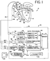
- Figure 1 is a schematic block diagram of a fully implantable atrial defibrillator embodying the present invention for applying defibrillating electrical energy to the atria of a human heart and which is shown in association with a human heart in need of atrial fibrillation monitoring and potential cardioversion of the atria.
- FIG. 2 is a flow diagram illustrating the manner in which the atrial defibrillator of Figure 1 may be implemented in accordance with the present invention for applying defibrillating or cardioverting electrical energy to the atria of the heart with reduced risk of inducing ventricular fibrillation.
- FIG. 1 it illustrates a fully implantable atrial defibrillator 30 embodying the present invention shown in association with a schematically illustrated human heart 10 in need of atrial fibrillation monitoring and potential cardioversion of the atria.
- the portions of the heart 10 illustrated in Figure 1 are the right ventricle 12, the left ventricle 14, the right atrium 16, the left atrium 18, the superior vena cava 20, the coronary sinus channel 21 which, as used herein, denotes the coronary sinus 22 and the great cardiac vein 23, the coronary sinus ostium or opening 24, the left ventricular free wall 26 and the inferior vena cava 27.
- the term "ventricular activations” denotes R waves of the heart cardiac cycle which are depolarizations of the ventricles 12 and 14.
- the atrial defibrillator 30 generally includes an enclosure 32 for hermetically sealing the internal circuit elements of the atrial defibrillator to be described hereinafter, an endocardial first lead 34, and an intravascular second lead 36.
- the enclosure 32 and first and second leads 34 and 36 are arranged to be implanted beneath the skin of a patient so as to render the atrial defibrillator 30 fully implantable.
- the endocardial first lead 34 preferably comprises a endocardial bi-polar lead having electrodes 38 and 40 arranged for establishing electrical contact with the right ventricle 12 of the heart 10.
- the electrodes 38 and 40 permit bi-polar sensing of R waves and T waves of the heart 10 in the right ventricle.
- the lead 34 is preferably fed through the superior vena cava 20, into the right atrium 16, and then into the right ventricle 12 as illustrated.
- the second lead 36 generally includes a first or tip electrode 44 and a second or proximal electrode 46.
- the second lead 36 is flexible and arranged to be passed down the superior vena cava 20, into the right atrium 16, into the coronary sinus ostium 24, and advanced into the coronary sinus channel 21 of the heart near the left side thereof so that the first or tip electrode 44 is within the coronary sinus channel 21 either within the coronary sinus 22 adjacent the left ventricle 14 and beneath the left atrium 18 or most preferably within the great cardiac vein 23 adjacent the left ventricle 14 and beneath the left atrium 18.
- the electrodes 44 and 46 are spaced apart such that when the first electrode 44 is positioned as described above, the second electrode 46 is in the right atrium 16.
- the first electrode 44 together with the second electrode 46 provide bi-polar sensing of heart activity in the atria 16 and 18.
- the first electrode 44 and the second electrode 46 further provide for the delivery of defibrillating electrical energy to the atria. Because the first electrode 44 is located beneath the left atrium 18 near the left ventricle 14 and the second electrode 46 is within the right atrium 16, the electrical energy applied between these electrodes will be substantially confined to the atria 16 and 18 of the heart 10. As a result, the electrical energy applied to the right ventricle 12 and left ventricle 14 when the atria are cardioverted or defibrillated will be minimized. This reduces the potential for ventricular fibrillation of the heart to be induced as a result of the application of defibrillating electrical energy of the atria of the heart.
- the atrial defibrillator 30 includes detecting means 49 including a T wave detector 51, a first sense amplifier 50, and an R wave detector 52.
- the inputs of sense amplifier 50 are coupled to electrodes 38 and 40 respectively of lead 34 for sensing electrical activity of the heart 10 in the right ventricle 12.
- the electrocardiogram (ECG) output of the sense amplifier is fed to both the R wave detector 52 and T wave detector 51.
- the R wave detector 52 forms a first detecting means which, responsive to the output of sense amplifier 50, detects R waves of the heart 10.
- the T wave detector 51 forms a second detecting means which, responsive to the output of sense amplifier 50, detects T waves of the heart 10.
- the R wave detector 52 and T wave detector 51 may be of the type known in the art. However, since both R waves and T waves are detected, it is preferable that the R wave detector 52 and T wave detector 51 have different detection characteristics so that a detected R wave is not confused with a detected T wave and vice versa.
- the enclosure 32 further includes a second sense amplifier 54 which is coupled to an analog to digital converter 56.
- the inputs of sense amplifier 54 are coupled to electrodes 44 and 46 respectively of lead 36 to form a third detecting means 53 for detecting atrial activity of the heart 10.
- the output of sense amplifier 54 provides an analog output representative of the atrial activity of the heart 10 which is fed to the analog to digital converter 56.
- the analog to digital converter 56 converts the analog signal representative of the atrial activity of the heart being detected to digital samples for further processing in a manner to be described hereinafter.
- the enclosure 32 of the atrial defibrillator 30 further includes a microprocessor 60.
- the implementation of the microprocessor 60 in accordance with this embodiment of the present invention results in a plurality of functional stages.
- the stages include a timer 62 including a first timer 64, a second timer 66 and a third timer 68, an atrial arrhythmia detector in the form of an atrial fibrillation detector 70, and a charge delivery and energy control stage 72.
- the microprocessor 60 is arranged to operate in conjunction with a memory 74 which may be coupled to the microprocessor 60 by a multiple-bit address bus 75 and a bi-directional multiple-bit databus 76. This permits the microprocessor 60 to address desired memory locations within the memory 74 for executing write or read operations.
- the microprocessor 60 stores data, such as time intervals or operating parameters in the memory at the addresses defined by multiple-bit addresses conveyed over the address bus 75 and conveys the data to the memory 74 over the multiple-bit data bus 76.
- the microprocessor 60 obtains data from the memory 74 at the storage locations identified by the multiple-bit addresses provided over the address bus 75 and receives the data from the memory over the bi-directional data bus 76.
- the microprocessor 60 receives programmable operating parameters from an external controller 100 which is external to the skin of the patient.
- the external controller 100 is arranged to communicate with a receiver/transmitter 102 which is coupled to the microprocessor 60 over a bi-directional bus 104.
- the receiver/transmitter 102 may be of the type well known in the art for conveying various information which it obtains from the microprocessor 60 to the external controller 100 or for receiving programming parameters from the external controller 100 which the receiver/transmitter 102 then conveys to the microprocessor 60 for storage in internal memory (not shown) or in the aforementioned external memory 74 within enclosure 32.
- the receiver/transmitter 102 includes a transmitting coil 106 so that the receiver/transmitter 102 and coil 106 form a communication means.
- Such communication means are well known in the art and may be utilized as noted above for receiving commands from external to the implantable enclosures 32 and for transmitting data to the external controller 100 from the implanted enclosure 32.
- One such communication system is disclosed, for example, in U.S. Patent No. 4,586,508.
- the atrial defibrillator 30 further includes a charger and storage capacitor circuit 80 of the type well known in the art which charges a storage capacitor to a predetermined voltage level and a discharge circuit 82 for discharging the storage capacitor within circuit 80 to provide a discharge output of electrical energy when required to the atria of the heart.
- the discharge circuit 82 is coupled to the first electrode 44 and the second electrode 46 of the second lead 36 for applying the cardioverting or defibrillating electrical energy to the atria.
- the defibrillator 30 includes a depletable power source 78, such a lithium battery, for providing power to the electrical components of the atrial defibrillator 30.
- the sense amplifier 50 and the R wave detector 52 continuously detect the occurrence of R waves (ventricular activations) of the right ventricle 12.
- the microprocessor 60 enables the atrial fibrillation detector 70, sense amplifier 54, and the analog to digital converter 56. If the atrial fibrillation detector 70 determines that the atria 16 and 18 are in fibrillation and thus in need of cardioversion, the charge delivery control 72 causes the charger and storage capacitor circuit 80 to charge the storage capacitor within circuit 80.
- the operation of the atrial defibrillator 30 then enters the implementation illustrated in the flow diagram of Figure 2.
- the microprocessor 60 first, in step 110, determines if an initial R wave has been detected by sense amplifier 50 and the R wave detector 52. If an initial R wave has not been detected, the microprocessor returns. If an initial R wave has been detected, the microprocessor then in step 112 resets to zero and starts the first timer 64 for timing a first predetermined time period.
- the duration of the first predetermined time period is preferably selected to have a time interval corresponding to the time interval following the detection of the initial R wave in step 110 in which a T wave would be expected to occur.
- the first predetermined time period may have a duration of 250 milliseconds.
- step 114 the microprocessor 60 then in step 114 waits for a period of 100 milliseconds. Hence, in step 114, as long as the microprocessor determines that the time on the first timer 64 is less than 100 milliseconds, the microprocessor repeats step 114. When the time on the first timer 64 reaches 100 milliseconds, the microprocessor proceeds to step 116 to determine if a T wave is being detected by the T wave detector 51. If a T wave is not being detected, the microprocessor proceeds to step 118 to determine if an R wave is being detected by the R wave detector 52.
- step 118 the microprocessor then proceeds to step 120 to determine if the timer 64 has completed the timing of the first predetermined time period. If the first timer 64 has not completed the timing of the first predetermined time period, the microprocessor returns to step 116 to once again determine if a T wave is being detected by the T wave detector 51.
- step 118 If in step 118 it is determined that an R wave is being detected prior to the first timer 64 completing the timing of the first predetermined time period, the microprocessor will return to restart the first timer 64 and thus to restart the timing of the first predetermined time period.
- the first timer 64 is responsive to the R wave detector 52 detecting an R wave within the first predetermined time period for retiming the first predetermined time period. This step is provided in case two successive R waves are detected without an intervening T wave being detected within the first predetermined time period. If such an R wave is detected in step 118 prior to the first timer 64 completing the timing of the first predetermined time period, the R wave detected in step 118 then becomes the initial detected R wave.
- step 120 If in step 120 it is determined that the first timer 64 has completed the timing of the first predetermined time period, the microprocessor then returns to step 110 for detecting a further initial R wave.
- the R wave detector 52 is responsive to the first timer 64 completing the timing of the first predetermined time period without a T wave or an R wave being detected to detect for a further initial R wave.
- step 116 If in step 116 a T wave is detected before timer 64 completes the timing of the first predetermined time period, the microprocessor then resets to zero and starts the second timer 66 in step 122.
- the second timer 66 times a predetermined delay time to assure that the T wave detected in step 116 is completed prior to the application of the cardioverting electrical energy to the atria of the heart in synchronism with the next detected R wave.
- the predetermined delay time may have a duration, for example, of 150 milliseconds. Hence, the second timer 66 only times the predetermined delay time when the T wave detector 51 detects a T wave within said first predetermined time period.
- the microprocessor after starting the second timer 66, proceeds to step 124 to determine if the second timer 64 has completed the timing of the predetermine delay time. If the second timer 66 has not completed the timing of the predetermined delay time, the microprocessor then proceeds to step 126 to determine if an R wave is being detected. If an R wave is being detected, the microprocessor returns to step 112 to restart the first timer 64. As a result, the R wave detected in step 126 will become the initial detected R wave.
- the first timer 64 is responsive to the R wave detector 52 detecting an R wave within the predetermined delay time for retiming the first predetermined time period.
- step 128 determines if a subsequent T wave is being detected. If a T wave is being detected in step 128, the microprocessor returns to step 110 for detecting a further initial R wave.
- the R wave detector 52 is responsive to the second timer 66 and to the T wave detector 51 detecting a further T wave during the predetermined delay time to detect for a further initial R wave. The implementation of step 128 assures that an R wave is not mistaken for a T wave detected in step 116.
- the microprocessor then proceeds to step 130 for resetting to zero and starting the third timer 68.
- the third timer 68 times up to a predetermined time period which is selected, as will be seen hereinafter, to assure that the current cardiac cycle is not excessively long.
- the heart rate may be highly variable resulting in increased vulnerability for inducing ventricular fibrillation. If the current cardiac cycle is too long, it may be followed by a short cardiac cycle resulting in increased vulnerability.
- a further condition is imposed prior to cardioversion.
- This further condition requires that the current cardiac cycle not be excessively long.
- the duration of the predetermined time period up to which the third timer 68 times may be, for example, 500 milliseconds.
- the microprocessor in step 132 determines if a T wave is being detected. If a T wave is being detected in step 132, the microprocessor returns to step 110 to detect for a further initial R wave.
- the R wave detector 52 is responsive to the T wave detector 51 detecting a further T wave before detecting the first R wave following the T wave detected in step 116 to detect for a further initial R wave.
- step 132 the microprocessor then proceeds to step 134 to determine if an R wave is being detected. If an R wave is not being detected in step 134, the microprocessor then proceeds to step 136 to determine if the third timer 68 has completed the timing of the predetermined time period. If the third timer 68 has completed the timing of the predetermined time period, the microprocessor returns to step 110 to detect for a further initial R wave. As a result, the R wave detector 52 is responsive to the third timer 68 completing the timing of the predetermined time period without detecting the first R wave following the T wave detected in step 116 to detect for a further initial R wave. If in step 136 the third timer 68 has not completed the timing of the predetermined time period, the microprocessor returns to step 132.
- step 134 the charge delivery and energy control 72 then causes the discharge circuit 82 to apply the cardioverting electrical energy to electrodes 44 and 46 and thus to the atria of the heart in step 138 in synchronism with the R wave detected in step 134.
- the cardioverting electrical energy is applied to the atria after a T wave is detected by the T wave detector 51 in step 116 and in timed relation to an R wave detected in step 134 wherein the R wave detected in step 134, by virtue of the predetermined delay time timed by the second timer 66, occurs and is detected at a time after the T wave detected in step 116 is completed to assure that the cardioverting electrical energy is not applied to the atria at a time when the heart is vulnerable to induced ventricular fibrillation.
- the R wave detected in step 134 is the first R wave detected after the completed T wave detected in step 116.
- the atrial defibrillator 30, and more specifically the charge delivery and energy control 72 when it is determined that the third timer 68 has completed the timing of the predetermined time period in step 136, the atrial defibrillator 30, and more specifically the charge delivery and energy control 72, withholds the application of the cardioverting electrical energy and restarts the entire sequence beginning with step 110. This assures that the atria are not cardioverted at the end of an excessively long cardiac cycle which, as previously mentioned, may be followed by a short cardiac cycle.
- the atrial defibrillator of the present invention precludes the application of cardioverting or defibrillating electrical energy to the atria of the heart in the presence of a possible vulnerable condition.
- the atrial defibrillator of the present invention precludes the application of the cardioverting energy at a time when a T wave has not been completed to reduce the risk of inducing ventricular fibrillation during the application of the cardioverting or defibrillating electrical energy to the atria of the heart.
- T wave detector 51 and R wave detector 52 may be implemented by the microprocessor 60 under operating instructions obtained from the memory 74.
- the hardware T wave detector 51 and R wave detectors 51 and 52 respectively may be eliminated.
- the microprocessor may be implemented for filtering the output of sense amplifier 50 with a high-pass filter at approximately 1.0 Hz and a low-pass filter at approximately 5.0 Hz. The microprocessor then may be implemented to calculate the derivative of the filtered signal using a discrete differentiation of the filtered data and refiltered with a low-pass filter at approximately 5.0 Hz.
- the detection of the T wave begins 100 milliseconds after the initial R wave is detected and continues for 150 milliseconds.
- the maximum positive and negative slopes may be detected by the microprocessor from the differentiated data in this time interval.
- the T wave may then be detected as the point between the maximum slopes where the average slope changes to zero or changes sign. To implement the foregoing, a slope averaging technique may be used.
- the microprocessor may be implemented to filter the output of the R wave detector 52 with a band pass filter characteristic centered at approximately 35 Hz. The microprocessor then calculates the absolute value of the filtered signal. Thereafter, the microprocessor may require four conditions to be met before an R wave is considered to be detected. The first condition is that the absolute value of the filtered signal exceed twice its low-pass (0.1 Hz) filtered value. The second condition is that the absolute value of the filtered signal exceed one-half the average peak values of the last three R waves detected.
- the fourth condition is that the time since the last R wave cannot be less than 150 milliseconds.
- steps 110, 112, 114, 118, and 120 may be eliminated such that the precardioversion interval timing process begins with step 116 as illustrated in Figure 2.
- the microprocessor would then return to step 116 to detect for a further T wave.
- the T wave detection and interval timing of the present invention may be utilized to advantage in an external atrial defibrillator wherein an electrode or electrodes adhered to the surface of the skin of a patient are employed along with R wave and T wave detectors for detecting R waves and T waves, and surface pad electrodes are utilized for applying the cardioverting electrical energy to the atria of the heart.
- an electrode or electrodes adhered to the surface of the skin of a patient are employed along with R wave and T wave detectors for detecting R waves and T waves, and surface pad electrodes are utilized for applying the cardioverting electrical energy to the atria of the heart.
- surface pad electrodes are well known in the art.
Abstract
Description
- The present invention generally relates to an atrial defibrillator for applying cardioverting electrical energy to the atria of a human heart in need of cardioversion. The present invention is more particularly directed to a fully automatic implantable atrial defibrillator which exhibits improved safety by reducing the potential risk of induced ventricular fibrillation which may result from the mistimed delivery of cardioverting electrical energy to the atria of the heart. More specifically, the atrial defibrillator of the present invention guards against applying cardioverting electrical energy to the atria of the heart under conditions believed to contribute to induced ventricular fibrillation.
- Atrial fibrillation is probably the most common cardiac arrhythmia. Although it is not usually a life threatening arrhythmia, it is associated with strokes thought to be caused by blood clots forming in areas of stagnant blood flow as a result of prolonged atrial fibrillation. In addition, patients afflicted with atrial fibrillation generally experience palpitations of the heart and may even experience dizziness or even loss of consciousness.
- Atrial fibrillation occurs suddenly and many times can only be corrected by a discharge of electrical energy to the heart through the skin of the patient by way of an external defibrillator of the type well known in the art. This treatment is commonly referred to as synchronized cardioversion and, as its name implies, involves applying electrical defibrillating energy to the heart in synchronism with a detected ventricular electrical activation (R wave) of the heart. The treatment is very painful and, unfortunately, most often only results in temporary relief for patients, lasting but a few weeks.
- Drugs are available for reducing the incidence of atrial fibrillation. However, these drugs have many side effects and many patients are resistent to them which greatly reduces their therapeutic effect.
- Implantable atrial defibrillators have been proposed to provide patients suffering from occurrences of atrial fibrillation with relief. Unfortunately, to the detriment of such patients, none of these atrial defibrillators have become a commercial reality.
- Implantable atrial defibrillators proposed in the past have exhibited a number of disadvantages which probably has precluded these defibrillators from becoming a commercial reality. Two such proposed defibrillators, although represented as being implantable, were not fully automatic, requiring human interaction for cardioverting or defibrillating the heart. Both of these proposed defibrillators require the patient to recognize the symptoms of atrial fibrillation with one defibrillator requiring a visit to a physician to activate the defibrillator and the other defibrillator requiring the patient to activate the defibrillator with an external magnet.
- Improved atrial defibrillators synchronize the delivery of the defibrillating or cardioverting electrical energy to the atria with a ventricular electrical activation (R wave) of the heart to prevent induced ventricular fibrillation. Ventricular fibrillation is a fatal arrhythmia which can be caused by electrical energy being delivered to the heart at the wrong time in the cardiac cycle, such as during the T wave of the cycle. The improved atrial defibrillators exhibit improved safety from inducing ventricular fibrillation by sensing ventricular activations of the heart in a manner which avoids detecting noise as ventricular electrical activations for generating reliable synchronization signals. Hence, these implantable atrial defibrillators, by providing such noise immunity in R wave detection assure reliable synchronization.
- Another measure for reducing the risk of inducing ventricular fibrillation during the delivery of cardioverting electrical energy to the atria of the heart employed by the defibrillators of the aforementioned referenced applications is the reduction of the amount of the electrical energy which is passed through the ventricles during cardioversion of the atria. This is achieved by locating the cardioverting electrodes in or near the heart to provide a cardioverting energy path which confines most of the cardioverting electrical energy to the atria of the heart.
- The atrial defibrillator and method of the present invention provides improved safety and reduction in the risk of inducing ventricular fibrillation during atrial cardioversion or defibrillation. It has been observed that during episodes of atrial fibrillation, the cardiac rate increases to a high rate and/or becomes extremely variable. At high cardiac rates, the R wave of each cardiac cycle becomes closely spaced from the T wave of the immediately preceding cardiac cycle. This may lead to a condition known in the art as an "R on T" condition which is believed to contribute to induced ventricular fibrillation if the atria are cardioverted in synchronism with the R wave close to the T wave. During highly variable cardiac rates, a long cardiac cycle can be followed by a relatively short cardiac cycle. This condition in conjunction with a high cardiac rate is believed to cause a dispersion of refractoriness and also can result in an increased vulnerability to ventricular fibrillation. The atrial defibrillator of the present invention guards against applying the cardioverting electrical energy to the atria when increased vulnerability to ventricular fibrillation may be present.
- The present invention therefore provides an implantable atrial defibrillator for providing cardioverting electrical energy to the atria of a human heart in need of cardioversion. The atrial defibrillator includes a first detector for detecting R waves of the heart, a second detector for detecting T waves of the heart, and a third detector for detecting atrial activity of the heart. The atrial defibrillator further includes an atrial fibrillation detector responsive to the third detector for determining when the atria of the heart are in need of cardioversion, and a cardiovertor for applying the cardioverting electrical energy to the atria of the heart when the atria of the heart are in need of cardioversion, after the second detector detects a T wave, and in timed relation to an R wave detected by the first detector after the detected T wave is completed. The R wave detected after the detected T wave is completed is the first R wave detected by the first detecting means after the detected T wave.
- Figure 1 is a schematic block diagram of a fully implantable atrial defibrillator embodying the present invention for applying defibrillating electrical energy to the atria of a human heart and which is shown in association with a human heart in need of atrial fibrillation monitoring and potential cardioversion of the atria.
- Figure 2 is a flow diagram illustrating the manner in which the atrial defibrillator of Figure 1 may be implemented in accordance with the present invention for applying defibrillating or cardioverting electrical energy to the atria of the heart with reduced risk of inducing ventricular fibrillation.
- Referring now to Figure 1, it illustrates a fully implantable
atrial defibrillator 30 embodying the present invention shown in association with a schematically illustratedhuman heart 10 in need of atrial fibrillation monitoring and potential cardioversion of the atria. The portions of theheart 10 illustrated in Figure 1 are theright ventricle 12, theleft ventricle 14, theright atrium 16, theleft atrium 18, thesuperior vena cava 20, the coronary sinus channel 21 which, as used herein, denotes the coronary sinus 22 and the greatcardiac vein 23, the coronary sinus ostium or opening 24, the left ventricularfree wall 26 and theinferior vena cava 27. In addition, as used herein, the term "ventricular activations" denotes R waves of the heart cardiac cycle which are depolarizations of theventricles - The
atrial defibrillator 30 generally includes anenclosure 32 for hermetically sealing the internal circuit elements of the atrial defibrillator to be described hereinafter, an endocardialfirst lead 34, and an intravascularsecond lead 36. Theenclosure 32 and first and second leads 34 and 36 are arranged to be implanted beneath the skin of a patient so as to render theatrial defibrillator 30 fully implantable. - The endocardial
first lead 34 preferably comprises a endocardial bi-polarlead having electrodes right ventricle 12 of theheart 10. Theelectrodes heart 10 in the right ventricle. As illustrated, thelead 34 is preferably fed through thesuperior vena cava 20, into theright atrium 16, and then into theright ventricle 12 as illustrated. - The
second lead 36 generally includes a first ortip electrode 44 and a second orproximal electrode 46. As illustrated, thesecond lead 36 is flexible and arranged to be passed down thesuperior vena cava 20, into theright atrium 16, into thecoronary sinus ostium 24, and advanced into the coronary sinus channel 21 of the heart near the left side thereof so that the first ortip electrode 44 is within the coronary sinus channel 21 either within the coronary sinus 22 adjacent theleft ventricle 14 and beneath theleft atrium 18 or most preferably within the greatcardiac vein 23 adjacent theleft ventricle 14 and beneath theleft atrium 18. Theelectrodes first electrode 44 is positioned as described above, thesecond electrode 46 is in theright atrium 16. Thefirst electrode 44 together with thesecond electrode 46 provide bi-polar sensing of heart activity in theatria first electrode 44 and thesecond electrode 46 further provide for the delivery of defibrillating electrical energy to the atria. Because thefirst electrode 44 is located beneath theleft atrium 18 near theleft ventricle 14 and thesecond electrode 46 is within theright atrium 16, the electrical energy applied between these electrodes will be substantially confined to theatria heart 10. As a result, the electrical energy applied to theright ventricle 12 andleft ventricle 14 when the atria are cardioverted or defibrillated will be minimized. This reduces the potential for ventricular fibrillation of the heart to be induced as a result of the application of defibrillating electrical energy of the atria of the heart. - Within the
enclosure 32, theatrial defibrillator 30 includes detecting means 49 including aT wave detector 51, afirst sense amplifier 50, and anR wave detector 52. The inputs ofsense amplifier 50 are coupled toelectrodes lead 34 for sensing electrical activity of theheart 10 in theright ventricle 12. The electrocardiogram (ECG) output of the sense amplifier is fed to both theR wave detector 52 andT wave detector 51. TheR wave detector 52 forms a first detecting means which, responsive to the output ofsense amplifier 50, detects R waves of theheart 10. TheT wave detector 51 forms a second detecting means which, responsive to the output ofsense amplifier 50, detects T waves of theheart 10. TheR wave detector 52 andT wave detector 51 may be of the type known in the art. However, since both R waves and T waves are detected, it is preferable that theR wave detector 52 andT wave detector 51 have different detection characteristics so that a detected R wave is not confused with a detected T wave and vice versa. - The
enclosure 32 further includes asecond sense amplifier 54 which is coupled to an analog todigital converter 56. The inputs ofsense amplifier 54 are coupled toelectrodes lead 36 to form a third detecting means 53 for detecting atrial activity of theheart 10. The output ofsense amplifier 54 provides an analog output representative of the atrial activity of theheart 10 which is fed to the analog todigital converter 56. The analog todigital converter 56 converts the analog signal representative of the atrial activity of the heart being detected to digital samples for further processing in a manner to be described hereinafter. - The
enclosure 32 of theatrial defibrillator 30 further includes amicroprocessor 60. The implementation of themicroprocessor 60 in accordance with this embodiment of the present invention results in a plurality of functional stages. The stages include atimer 62 including afirst timer 64, a second timer 66 and athird timer 68, an atrial arrhythmia detector in the form of an atrial fibrillation detector 70, and a charge delivery and energy control stage 72. - The
microprocessor 60 is arranged to operate in conjunction with amemory 74 which may be coupled to themicroprocessor 60 by a multiple-bit address bus 75 and a bi-directional multiple-bit databus 76. This permits themicroprocessor 60 to address desired memory locations within thememory 74 for executing write or read operations. During a write operation, themicroprocessor 60 stores data, such as time intervals or operating parameters in the memory at the addresses defined by multiple-bit addresses conveyed over theaddress bus 75 and conveys the data to thememory 74 over the multiple-bit data bus 76. During a read operation, themicroprocessor 60 obtains data from thememory 74 at the storage locations identified by the multiple-bit addresses provided over theaddress bus 75 and receives the data from the memory over thebi-directional data bus 76. - For entering operating parameters into the
microprocessor 60, themicroprocessor 60 receives programmable operating parameters from anexternal controller 100 which is external to the skin of the patient. Theexternal controller 100 is arranged to communicate with a receiver/transmitter 102 which is coupled to themicroprocessor 60 over a bi-directional bus 104. The receiver/transmitter 102 may be of the type well known in the art for conveying various information which it obtains from themicroprocessor 60 to theexternal controller 100 or for receiving programming parameters from theexternal controller 100 which the receiver/transmitter 102 then conveys to themicroprocessor 60 for storage in internal memory (not shown) or in the aforementionedexternal memory 74 withinenclosure 32. - The receiver/
transmitter 102 includes a transmittingcoil 106 so that the receiver/transmitter 102 andcoil 106 form a communication means. Such communication means are well known in the art and may be utilized as noted above for receiving commands from external to theimplantable enclosures 32 and for transmitting data to theexternal controller 100 from the implantedenclosure 32. One such communication system is disclosed, for example, in U.S. Patent No. 4,586,508. - To complete the identification of the various structural elements within the
enclosure 32, theatrial defibrillator 30 further includes a charger andstorage capacitor circuit 80 of the type well known in the art which charges a storage capacitor to a predetermined voltage level and adischarge circuit 82 for discharging the storage capacitor withincircuit 80 to provide a discharge output of electrical energy when required to the atria of the heart. To that end, thedischarge circuit 82 is coupled to thefirst electrode 44 and thesecond electrode 46 of thesecond lead 36 for applying the cardioverting or defibrillating electrical energy to the atria. Lastly, thedefibrillator 30 includes adepletable power source 78, such a lithium battery, for providing power to the electrical components of theatrial defibrillator 30. - The
sense amplifier 50 and theR wave detector 52 continuously detect the occurrence of R waves (ventricular activations) of theright ventricle 12. When the time intervals between immediately successive R waves indicate the probability of an episode of atrial fibrillation, themicroprocessor 60 enables the atrial fibrillation detector 70,sense amplifier 54, and the analog todigital converter 56. If the atrial fibrillation detector 70 determines that theatria storage capacitor circuit 80 to charge the storage capacitor withincircuit 80. The operation of theatrial defibrillator 30 then enters the implementation illustrated in the flow diagram of Figure 2. - Referring now to Figure 2, the
microprocessor 60 first, instep 110, determines if an initial R wave has been detected bysense amplifier 50 and theR wave detector 52. If an initial R wave has not been detected, the microprocessor returns. If an initial R wave has been detected, the microprocessor then instep 112 resets to zero and starts thefirst timer 64 for timing a first predetermined time period. The duration of the first predetermined time period is preferably selected to have a time interval corresponding to the time interval following the detection of the initial R wave instep 110 in which a T wave would be expected to occur. As an example, the first predetermined time period may have a duration of 250 milliseconds. - Once the
first timer 64 is started instep 112, themicroprocessor 60 then instep 114 waits for a period of 100 milliseconds. Hence, instep 114, as long as the microprocessor determines that the time on thefirst timer 64 is less than 100 milliseconds, the microprocessor repeatsstep 114. When the time on thefirst timer 64reaches 100 milliseconds, the microprocessor proceeds to step 116 to determine if a T wave is being detected by theT wave detector 51. If a T wave is not being detected, the microprocessor proceeds to step 118 to determine if an R wave is being detected by theR wave detector 52. If an R wave is not being detected instep 118, the microprocessor then proceeds to step 120 to determine if thetimer 64 has completed the timing of the first predetermined time period. If thefirst timer 64 has not completed the timing of the first predetermined time period, the microprocessor returns to step 116 to once again determine if a T wave is being detected by theT wave detector 51. - If in
step 118 it is determined that an R wave is being detected prior to thefirst timer 64 completing the timing of the first predetermined time period, the microprocessor will return to restart thefirst timer 64 and thus to restart the timing of the first predetermined time period. Hence, thefirst timer 64 is responsive to theR wave detector 52 detecting an R wave within the first predetermined time period for retiming the first predetermined time period. This step is provided in case two successive R waves are detected without an intervening T wave being detected within the first predetermined time period. If such an R wave is detected instep 118 prior to thefirst timer 64 completing the timing of the first predetermined time period, the R wave detected instep 118 then becomes the initial detected R wave. - If in step 120 it is determined that the
first timer 64 has completed the timing of the first predetermined time period, the microprocessor then returns to step 110 for detecting a further initial R wave. Hence, theR wave detector 52 is responsive to thefirst timer 64 completing the timing of the first predetermined time period without a T wave or an R wave being detected to detect for a further initial R wave. - If in step 116 a T wave is detected before
timer 64 completes the timing of the first predetermined time period, the microprocessor then resets to zero and starts the second timer 66 instep 122. The second timer 66 times a predetermined delay time to assure that the T wave detected instep 116 is completed prior to the application of the cardioverting electrical energy to the atria of the heart in synchronism with the next detected R wave. The predetermined delay time may have a duration, for example, of 150 milliseconds. Hence, the second timer 66 only times the predetermined delay time when theT wave detector 51 detects a T wave within said first predetermined time period. - The microprocessor, after starting the second timer 66, proceeds to step 124 to determine if the
second timer 64 has completed the timing of the predetermine delay time. If the second timer 66 has not completed the timing of the predetermined delay time, the microprocessor then proceeds to step 126 to determine if an R wave is being detected. If an R wave is being detected, the microprocessor returns to step 112 to restart thefirst timer 64. As a result, the R wave detected instep 126 will become the initial detected R wave. Hence, thefirst timer 64 is responsive to theR wave detector 52 detecting an R wave within the predetermined delay time for retiming the first predetermined time period. - If an R wave is not being detected in
step 126, the microprocessor proceeds to step 128 to determine if a subsequent T wave is being detected. If a T wave is being detected instep 128, the microprocessor returns to step 110 for detecting a further initial R wave. Hence, theR wave detector 52 is responsive to the second timer 66 and to theT wave detector 51 detecting a further T wave during the predetermined delay time to detect for a further initial R wave. The implementation ofstep 128 assures that an R wave is not mistaken for a T wave detected instep 116. - If the second timer 66 completes the timing of the predetermined delay time without an R wave being detected in
step 126 or a T wave being detected instep 128, the microprocessor then proceeds to step 130 for resetting to zero and starting thethird timer 68. Thethird timer 68 times up to a predetermined time period which is selected, as will be seen hereinafter, to assure that the current cardiac cycle is not excessively long. As previously mentioned, during atrial fibrillation, the heart rate may be highly variable resulting in increased vulnerability for inducing ventricular fibrillation. If the current cardiac cycle is too long, it may be followed by a short cardiac cycle resulting in increased vulnerability. As a result, with thethird timer 68 timing up to a predetermined time period, a further condition is imposed prior to cardioversion. This further condition requires that the current cardiac cycle not be excessively long. The duration of the predetermined time period up to which thethird timer 68 times may be, for example, 500 milliseconds. - After the
third timer 68 is started, the microprocessor instep 132 determines if a T wave is being detected. If a T wave is being detected instep 132, the microprocessor returns to step 110 to detect for a further initial R wave. Hence, theR wave detector 52 is responsive to theT wave detector 51 detecting a further T wave before detecting the first R wave following the T wave detected instep 116 to detect for a further initial R wave. - If a T wave is not being detected in
step 132, the microprocessor then proceeds to step 134 to determine if an R wave is being detected. If an R wave is not being detected instep 134, the microprocessor then proceeds to step 136 to determine if thethird timer 68 has completed the timing of the predetermined time period. If thethird timer 68 has completed the timing of the predetermined time period, the microprocessor returns to step 110 to detect for a further initial R wave. As a result, theR wave detector 52 is responsive to thethird timer 68 completing the timing of the predetermined time period without detecting the first R wave following the T wave detected instep 116 to detect for a further initial R wave. If instep 136 thethird timer 68 has not completed the timing of the predetermined time period, the microprocessor returns to step 132. - If in
step 134 the microprocessor determines that an R wave is being detected, the charge delivery and energy control 72 then causes thedischarge circuit 82 to apply the cardioverting electrical energy toelectrodes step 134. As a result, the cardioverting electrical energy is applied to the atria after a T wave is detected by theT wave detector 51 instep 116 and in timed relation to an R wave detected instep 134 wherein the R wave detected instep 134, by virtue of the predetermined delay time timed by the second timer 66, occurs and is detected at a time after the T wave detected instep 116 is completed to assure that the cardioverting electrical energy is not applied to the atria at a time when the heart is vulnerable to induced ventricular fibrillation. As will be further noted, the R wave detected instep 134 is the first R wave detected after the completed T wave detected instep 116. - As will also be noted in Figure 2, when it is determined that the
third timer 68 has completed the timing of the predetermined time period instep 136, theatrial defibrillator 30, and more specifically the charge delivery and energy control 72, withholds the application of the cardioverting electrical energy and restarts the entire sequence beginning withstep 110. This assures that the atria are not cardioverted at the end of an excessively long cardiac cycle which, as previously mentioned, may be followed by a short cardiac cycle. - As a result of the foregoing, the atrial defibrillator of the present invention precludes the application of cardioverting or defibrillating electrical energy to the atria of the heart in the presence of a possible vulnerable condition. To that end, the atrial defibrillator of the present invention precludes the application of the cardioverting energy at a time when a T wave has not been completed to reduce the risk of inducing ventricular fibrillation during the application of the cardioverting or defibrillating electrical energy to the atria of the heart.
- While a particular embodiment of the present invention has been shown and described, modifications may be made. For example, the functions of the
T wave detector 51 andR wave detector 52 may be implemented by themicroprocessor 60 under operating instructions obtained from thememory 74. As a result, the hardwareT wave detector 51 andR wave detectors - For software implemented T wave detection, the microprocessor may be implemented for filtering the output of
sense amplifier 50 with a high-pass filter at approximately 1.0 Hz and a low-pass filter at approximately 5.0 Hz. The microprocessor then may be implemented to calculate the derivative of the filtered signal using a discrete differentiation of the filtered data and refiltered with a low-pass filter at approximately 5.0 Hz. The detection of the T wave, in accordance with the flow diagram of Figure 2, begins 100 milliseconds after the initial R wave is detected and continues for 150 milliseconds. The maximum positive and negative slopes may be detected by the microprocessor from the differentiated data in this time interval. The T wave may then be detected as the point between the maximum slopes where the average slope changes to zero or changes sign. To implement the foregoing, a slope averaging technique may be used. - For software implemented R wave detection, the microprocessor may be implemented to filter the output of the
R wave detector 52 with a band pass filter characteristic centered at approximately 35 Hz. The microprocessor then calculates the absolute value of the filtered signal. Thereafter, the microprocessor may require four conditions to be met before an R wave is considered to be detected. The first condition is that the absolute value of the filtered signal exceed twice its low-pass (0.1 Hz) filtered value. The second condition is that the absolute value of the filtered signal exceed one-half the average peak values of the last three R waves detected. The third condition is that the absolute value of the filtered signal must exceed a value set by the following relationship:

where Vlast is the peak of the absolute value of the last R wave detected and t is the time since the last R wave. Lastly, the fourth condition is that the time since the last R wave cannot be less than 150 milliseconds. When all four of these conditions are met, the microprocessor then may consider an R wave to have been detected. - As a further modification,
steps step 116 as illustrated in Figure 2. In accordance with this modified embodiment, if an R wave is detected before the completion of the predetermined delay time, the microprocessor would then return to step 116 to detect for a further T wave. - Lastly, the T wave detection and interval timing of the present invention may be utilized to advantage in an external atrial defibrillator wherein an electrode or electrodes adhered to the surface of the skin of a patient are employed along with R wave and T wave detectors for detecting R waves and T waves, and surface pad electrodes are utilized for applying the cardioverting electrical energy to the atria of the heart. Such surface detecting and pad electrodes are well known in the art.
Claims (11)
- An implantable atrial defibrillator for providing cardioverting electrical energy to the atria of a human heart in need of cardioversion, the atrial defibrillator characterized by:
a first detector (52) for detecting R waves of the heart;
a second detector (51) for detecting T waves of the heart;
a third detector (53) for detecting atrial activity of the heart;
an atrial fibrillation detector (70) responsive to the third detector for determining when the atria of the heart are in need of cardioversion; and
a cardiovertor (82) for applying the cardioverting electrical energy to the atria of the heart when the atria of the heart are in need of cardioversion, after the second detector detects a T wave, and in timed relation to an R wave detected by the first detector after the detected T wave is completed, the R wave detected after the detected T wave is completed being the first R wave detected by the first detector after the detected T wave. - The atrial defibrillator of claim 1 further characterized in that the cardiovertor applies the cardioverting electrical energy in synchronism with the first R wave detected after the detected T wave.
- The atrial defibrillator of claim 1 further characterized by a timer (62) responsive to the second detector for timing a predetermined delay time upon the detection of the detected T wave and the cardiovertor being further responsive to the timer for applying the cardioverting electrical energy to the atria of the heart after the timer has timed the predetermined delay time and in timed relation to the R wave detected after the detected T wave.
- The atrial defibrillator of claim 3 further characterized in that the timer times a predetermined time period after the predetermined delay time and wherein the cardiovertor is responsive to the timer for withholding the application of the cardioverting electrical energy when the timing of the predetermined time period is completed before an R wave is detected by the first detector.
- The atrial defibrillator of claim 4 further characterized in that the timer is responsive to the first detector detecting an initial R wave for timing a first predetermined time period and wherein the timer only times the predetermined delay time when the detected T wave is detected within the first predetermined time period.
- The atrial defibrillator of claim 5 further characterized in that the timer is responsive to the first detector detecting an R wave within the first predetermined time period for retiming the first predetermined time period.
- The atrial defibrillator of claim 5 further characterized in that the timer is responsive to the first detector detecting an R wave within the predetermined delay time for retiming the first predetermined time period.
- The atrial defibrillator of claim 5 further characterized in that the first detector is responsive to the timer completing the timing of the first predetermined time period without a T wave being detected to detect for a further initial R wave.
- The atrial defibrillator of claim 5 further characterized in that the first detector is responsive to the timer and to the second detector detecting a further T wave during the predetermined delay time to detect for a further initial R wave.
- The atrial defibrillator of claim 5 further characterized in that the first detector is responsive to the second detector detecting a further T wave before detecting the first R wave to detect for a further initial R wave.
- The atrial defibrillator of claim 5 further characterized in that the first detector is responsive to the timer completing the timing of the predetermined time period without the first detector detecting the first R wave to detect for a further initial R wave.
Applications Claiming Priority (2)
| Application Number | Priority Date | Filing Date | Title |
|---|---|---|---|
| US67688 | 1979-08-20 | ||
| US08/067,688 US5350402A (en) | 1993-05-26 | 1993-05-26 | Atrial defibrillator and method for providing T wave detection and interval timing prior to cardioversion |
Publications (3)
| Publication Number | Publication Date |
|---|---|
| EP0627240A2 true EP0627240A2 (en) | 1994-12-07 |
| EP0627240A3 EP0627240A3 (en) | 1996-02-07 |
| EP0627240B1 EP0627240B1 (en) | 2001-01-03 |
Family
ID=22077701
Family Applications (1)
| Application Number | Title | Priority Date | Filing Date |
|---|---|---|---|
| EP94250138A Expired - Lifetime EP0627240B1 (en) | 1993-05-26 | 1994-05-19 | Atrial defibrillator for providing T wave detection and interval timing prior to cardioversion |
Country Status (6)
| Country | Link |
|---|---|
| US (1) | US5350402A (en) |
| EP (1) | EP0627240B1 (en) |
| JP (1) | JPH06335533A (en) |
| AU (1) | AU667168B2 (en) |
| CA (1) | CA2122432C (en) |
| DE (1) | DE69426506T2 (en) |
Cited By (1)
| Publication number | Priority date | Publication date | Assignee | Title |
|---|---|---|---|---|
| EP1109597A1 (en) * | 1998-09-03 | 2001-06-27 | Cardiac Pacemakers, Inc. | Cardioverter and method for cardioverting an atrial tachyarrhythmia in the presence of atrial pacing |
Families Citing this family (29)
| Publication number | Priority date | Publication date | Assignee | Title |
|---|---|---|---|---|
| US5735876A (en) * | 1994-05-31 | 1998-04-07 | Galvani Ltd. | Electrical cardiac output forcing method and apparatus for an atrial defibrillator |
| US6853859B1 (en) * | 1994-05-31 | 2005-02-08 | Galvani, Ltd. | Electrical cardiac output forcer |
| US5925066A (en) * | 1995-10-26 | 1999-07-20 | Galvani, Ltd. | Atrial arrythmia sensor with drug and electrical therapy control apparatus |
| US6185457B1 (en) * | 1994-05-31 | 2001-02-06 | Galvani, Ltd. | Method and apparatus for electrically forcing cardiac output in an arrhythmia patient |
| US5987354A (en) * | 1996-08-13 | 1999-11-16 | Uab Research Foundation | Dual shock atrial defibrillation apparatus |
| US6006131A (en) * | 1996-08-13 | 1999-12-21 | Uab Research Foundation | Dual current pathway atrial defibrillation apparatus |
| US5792188A (en) * | 1997-01-23 | 1998-08-11 | Pacesetter, Inc. | Capacitor reformation and measurement in an implantable cardioverter/defibrillator (ICD) |
| US5836971A (en) * | 1997-02-26 | 1998-11-17 | Pacesetter, Inc. | Dynamic rezoning of a tiered therapy inplantable cardioverter defibrillator/pacemaker (ICD) device |
| US5843130A (en) * | 1997-03-31 | 1998-12-01 | Masood Akhtar | System for delivering atrial defibrillation shocks |
| US5814081A (en) * | 1997-04-07 | 1998-09-29 | Incontrol, Inc. | Atrial flutter cardioverter and method |
| US5800497A (en) * | 1997-07-17 | 1998-09-01 | Medtronic, Inc. | Medical electrical lead with temporarily stiff portion |
| US6081745A (en) * | 1998-08-17 | 2000-06-27 | Medtronic, Inc. | Method and apparatus for treatment of arrhythmias |
| SE9901966D0 (en) | 1999-05-28 | 1999-05-28 | Pacesetter Ab | Implantable heart stimulator |
| WO2002048074A1 (en) | 2000-12-11 | 2002-06-20 | Nippon Soda Co.,Ltd. | Method for producing molecular compound |
| US6484057B2 (en) | 2000-12-21 | 2002-11-19 | Uab Research Foundation | Pacing methods and devices for treating cardiac arrhythmias and fibrillation |
| US6889077B2 (en) * | 2002-02-28 | 2005-05-03 | Pacesetter, Inc. | Implantable cardiac stimulation device that defibrillates the atria while avoiding the ventricular vulnerable period and method |
| US7139608B2 (en) * | 2002-07-31 | 2006-11-21 | Uab Research Foundation | Pacing methods and devices using feedback controlled timing |
| US8560063B2 (en) * | 2002-09-10 | 2013-10-15 | Uab Research Foundation | Post-defibrillation pacing methods and devices |
| US20040049118A1 (en) * | 2002-09-10 | 2004-03-11 | Ideker Raymond E. | Methods, systems and computer program products for treating fibrillation in a patient based on the presence of fibrillation following administration of defibrillation therapy |
| US7162298B2 (en) * | 2002-09-10 | 2007-01-09 | Uab Research Foundation | Devices for detecting the presence of cardiac activity following administration of defibrillation therapy |
| US7522958B2 (en) * | 2003-03-13 | 2009-04-21 | Uab Research Foundation | Methods and systems for reducing discomfort from cardiac defibrillation shocks |
| US7734344B2 (en) | 2003-12-02 | 2010-06-08 | Uab Research Foundation | Methods, systems and computer program products to inhibit ventricular fibrillation during cardiopulmonary resuscitation |
| US8401637B2 (en) * | 2004-11-24 | 2013-03-19 | Galvani, Ltd. | Medium voltage therapy applications in treating cardiac arrest |
| US7532928B2 (en) * | 2006-02-15 | 2009-05-12 | Biotronik Crm Patent Ag | Atrial defibrillator |
| US8483822B1 (en) | 2009-07-02 | 2013-07-09 | Galvani, Ltd. | Adaptive medium voltage therapy for cardiac arrhythmias |
| JP6099358B2 (en) * | 2012-10-30 | 2017-03-22 | オリンパス株式会社 | Fibrillation detector and defibrillator |
| US8750990B1 (en) | 2012-12-12 | 2014-06-10 | Galvani, Ltd. | Coordinated medium voltage therapy for improving effectiveness of defibrillation therapy |
| US20200126391A1 (en) * | 2018-10-22 | 2020-04-23 | Nicole Lovett | Drowning Prevention System |
| EP4225144A1 (en) * | 2020-10-08 | 2023-08-16 | Cardiac Pacemakers, Inc. | Cardiac beat classification to avoid delivering shock during ventricular repolarization |
Citations (6)
| Publication number | Priority date | Publication date | Assignee | Title |
|---|---|---|---|---|
| US3952750A (en) * | 1974-04-25 | 1976-04-27 | Mieczyslaw Mirowski | Command atrial cardioverting device |
| EP0058606A1 (en) * | 1981-02-17 | 1982-08-25 | Medtronic, Inc. | Atrial and ventricular pacemaker |
| EP0401962A2 (en) * | 1989-06-06 | 1990-12-12 | Ventritex, Inc. | Device for combined cardiac pacing and defibrillation |
| WO1992018198A2 (en) * | 1991-04-12 | 1992-10-29 | Incontrol, Inc. | Improved atrial defibrillator, lead systems, and method |
| WO1993002746A1 (en) * | 1991-07-30 | 1993-02-18 | Medtronic, Inc. | Method and apparatus for tachyarrhythmia detection and treatment |
| US5207219A (en) * | 1992-10-23 | 1993-05-04 | Incontrol, Inc. | Atrial defibrillator and method for providing interval timing prior to cardioversion |
Family Cites Families (1)
| Publication number | Priority date | Publication date | Assignee | Title |
|---|---|---|---|---|
| US5269298A (en) * | 1992-10-23 | 1993-12-14 | Incontrol, Inc. | Atrial defibrillator and method for providing synchronized delayed cardioversion |
-
1993
- 1993-05-26 US US08/067,688 patent/US5350402A/en not_active Expired - Lifetime
-
1994
- 1994-04-28 CA CA002122432A patent/CA2122432C/en not_active Expired - Fee Related
- 1994-05-19 DE DE69426506T patent/DE69426506T2/en not_active Expired - Lifetime
- 1994-05-19 EP EP94250138A patent/EP0627240B1/en not_active Expired - Lifetime
- 1994-05-23 AU AU63264/94A patent/AU667168B2/en not_active Ceased
- 1994-05-24 JP JP6109607A patent/JPH06335533A/en active Pending
Patent Citations (6)
| Publication number | Priority date | Publication date | Assignee | Title |
|---|---|---|---|---|
| US3952750A (en) * | 1974-04-25 | 1976-04-27 | Mieczyslaw Mirowski | Command atrial cardioverting device |
| EP0058606A1 (en) * | 1981-02-17 | 1982-08-25 | Medtronic, Inc. | Atrial and ventricular pacemaker |
| EP0401962A2 (en) * | 1989-06-06 | 1990-12-12 | Ventritex, Inc. | Device for combined cardiac pacing and defibrillation |
| WO1992018198A2 (en) * | 1991-04-12 | 1992-10-29 | Incontrol, Inc. | Improved atrial defibrillator, lead systems, and method |
| WO1993002746A1 (en) * | 1991-07-30 | 1993-02-18 | Medtronic, Inc. | Method and apparatus for tachyarrhythmia detection and treatment |
| US5207219A (en) * | 1992-10-23 | 1993-05-04 | Incontrol, Inc. | Atrial defibrillator and method for providing interval timing prior to cardioversion |
Cited By (2)
| Publication number | Priority date | Publication date | Assignee | Title |
|---|---|---|---|---|
| EP1109597A1 (en) * | 1998-09-03 | 2001-06-27 | Cardiac Pacemakers, Inc. | Cardioverter and method for cardioverting an atrial tachyarrhythmia in the presence of atrial pacing |
| EP1109597A4 (en) * | 1998-09-03 | 2008-11-05 | Cardiac Pacemakers Inc | Cardioverter and method for cardioverting an atrial tachyarrhythmia in the presence of atrial pacing |
Also Published As
| Publication number | Publication date |
|---|---|
| AU667168B2 (en) | 1996-03-07 |
| EP0627240B1 (en) | 2001-01-03 |
| JPH06335533A (en) | 1994-12-06 |
| US5350402A (en) | 1994-09-27 |
| CA2122432A1 (en) | 1994-11-27 |
| EP0627240A3 (en) | 1996-02-07 |
| DE69426506D1 (en) | 2001-02-08 |
| AU6326494A (en) | 1994-12-01 |
| DE69426506T2 (en) | 2001-05-10 |
| CA2122432C (en) | 1998-11-24 |
Similar Documents
| Publication | Publication Date | Title |
|---|---|---|
| EP0627240B1 (en) | Atrial defibrillator for providing T wave detection and interval timing prior to cardioversion | |
| US5269298A (en) | Atrial defibrillator and method for providing synchronized delayed cardioversion | |
| CA2095688C (en) | Atrial defibrillator and method for providing interval timing prior to cardioversion | |
| US5332400A (en) | Atrial defibrillator and method for providing pre-cardioversion warning | |
| US5282836A (en) | Atrial defibrillator and method for providing pre-cardioversion pacing | |
| CA2154727C (en) | Atrial defibrillator and method for providing interval timing of successive intervals prior to cardioversion | |
| US5265600A (en) | Atrial defibrillator and method for providing post-cardioversion pacing | |
| US5584864A (en) | Cardioversion synchronization system and method for an atrial defibrillator | |
| US5522850A (en) | Defibrillation and method for cardioverting a heart and storing related activity data | |
| EP0693301B1 (en) | System for reducing false positives in atrial fibrillation detection | |
| US5458621A (en) | Automatic gain control and method for enabling detection of low and high amplitude depolarization activation waves of the heart and atrial defibrillator utilizing the same | |
| US5827197A (en) | System for detecting atrial fibrillation notwithstanding high and variable ventricular rates | |
| EP0594273B1 (en) | Atrial defibrillator for providing improved atrial sensing | |
| US5464433A (en) | Atrial defibrillator and method providing dual reset of an interval timer | |
| EP0870519A2 (en) | Atrial flutter cardioverter | |
| CA2318137A1 (en) | Method and system for detecting dislodgement of an implanted right atrial endocardial lead | |
| US6249699B1 (en) | Cardioverter and method for cardioverting an atrial tachyarrhythmia in the presence of atrial pacing | |
| US5441519A (en) | Implantable atrial defibrillator having delayed intervention therapy | |
| US5507780A (en) | Selective default data storage for an implantable atrial defibrillator | |
| US6067469A (en) | Method and system for detecting dislodgment of an implanted right atrial endocardial lead using a sensing period derived from a ventricular lead | |
| EP0770410B1 (en) | An implantable atrial defibrillator having cardioverting output voltage limiting for simulating larger storage capacitors | |
| US5554175A (en) | Therapy termination in an atrial defibrillator and method | |
| US6018681A (en) | Implantable atrial defibrillator having therapy inhibition responsive to atrial cycle length |
Legal Events
| Date | Code | Title | Description |
|---|---|---|---|
| PUAI | Public reference made under article 153(3) epc to a published international application that has entered the european phase |
Free format text: ORIGINAL CODE: 0009012 |
|
| AK | Designated contracting states |
Kind code of ref document: A2 Designated state(s): BE DE ES FR GB IT NL |
|
| PUAL | Search report despatched |
Free format text: ORIGINAL CODE: 0009013 |
|
| AK | Designated contracting states |
Kind code of ref document: A3 Designated state(s): BE DE ES FR GB IT NL |
|
| 17P | Request for examination filed |
Effective date: 19960315 |
|
| 17Q | First examination report despatched |
Effective date: 19990415 |
|
| RAP1 | Party data changed (applicant data changed or rights of an application transferred) |
Owner name: CARDIAC PACEMAKERS, INC. |
|
| GRAG | Despatch of communication of intention to grant |
Free format text: ORIGINAL CODE: EPIDOS AGRA |
|
| RTI1 | Title (correction) |
Free format text: ATRIAL DEFIBRILLATOR FOR PROVIDING T WAVE DETECTION AND INTERVAL TIMING PRIOR TO CARDIOVERSION |
|
| 17Q | First examination report despatched |
Effective date: 19990415 |
|
| GRAG | Despatch of communication of intention to grant |
Free format text: ORIGINAL CODE: EPIDOS AGRA |
|
| GRAH | Despatch of communication of intention to grant a patent |
Free format text: ORIGINAL CODE: EPIDOS IGRA |
|
| GRAH | Despatch of communication of intention to grant a patent |
Free format text: ORIGINAL CODE: EPIDOS IGRA |
|
| GRAA | (expected) grant |
Free format text: ORIGINAL CODE: 0009210 |
|
| AK | Designated contracting states |
Kind code of ref document: B1 Designated state(s): BE DE ES FR GB IT NL |
|
| PG25 | Lapsed in a contracting state [announced via postgrant information from national office to epo] |
Ref country code: ES Free format text: THE PATENT HAS BEEN ANNULLED BY A DECISION OF A NATIONAL AUTHORITY Effective date: 20010103 |
|
| ITF | It: translation for a ep patent filed |
Owner name: ING. A. GIAMBROCONO & C. S.R.L. |
|
| REF | Corresponds to: |
Ref document number: 69426506 Country of ref document: DE Date of ref document: 20010208 |
|
| ET | Fr: translation filed | ||
| PLBE | No opposition filed within time limit |
Free format text: ORIGINAL CODE: 0009261 |
|
| STAA | Information on the status of an ep patent application or granted ep patent |
Free format text: STATUS: NO OPPOSITION FILED WITHIN TIME LIMIT |
|
| REG | Reference to a national code |
Ref country code: GB Ref legal event code: IF02 |
|
| 26N | No opposition filed | ||
| PGFP | Annual fee paid to national office [announced via postgrant information from national office to epo] |
Ref country code: NL Payment date: 20070524 Year of fee payment: 14 |
|
| PGFP | Annual fee paid to national office [announced via postgrant information from national office to epo] |
Ref country code: BE Payment date: 20070615 Year of fee payment: 14 |
|
| PGFP | Annual fee paid to national office [announced via postgrant information from national office to epo] |
Ref country code: GB Payment date: 20070525 Year of fee payment: 14 |
|
| PGFP | Annual fee paid to national office [announced via postgrant information from national office to epo] |
Ref country code: IT Payment date: 20070608 Year of fee payment: 14 |
|
| PGFP | Annual fee paid to national office [announced via postgrant information from national office to epo] |
Ref country code: FR Payment date: 20070517 Year of fee payment: 14 |
|
| BERE | Be: lapsed |
Owner name: *CARDIAC PACEMAKERS INC. Effective date: 20080531 |
|
| GBPC | Gb: european patent ceased through non-payment of renewal fee |
Effective date: 20080519 |
|
| PG25 | Lapsed in a contracting state [announced via postgrant information from national office to epo] |
Ref country code: NL Free format text: LAPSE BECAUSE OF NON-PAYMENT OF DUE FEES Effective date: 20081201 |
|
| REG | Reference to a national code |
Ref country code: FR Ref legal event code: ST Effective date: 20090119 |
|
| PG25 | Lapsed in a contracting state [announced via postgrant information from national office to epo] |
Ref country code: BE Free format text: LAPSE BECAUSE OF NON-PAYMENT OF DUE FEES Effective date: 20080531 |
|
| PG25 | Lapsed in a contracting state [announced via postgrant information from national office to epo] |
Ref country code: FR Free format text: LAPSE BECAUSE OF NON-PAYMENT OF DUE FEES Effective date: 20080602 |
|
| PG25 | Lapsed in a contracting state [announced via postgrant information from national office to epo] |
Ref country code: GB Free format text: LAPSE BECAUSE OF NON-PAYMENT OF DUE FEES Effective date: 20080519 |
|
| PG25 | Lapsed in a contracting state [announced via postgrant information from national office to epo] |
Ref country code: IT Free format text: LAPSE BECAUSE OF NON-PAYMENT OF DUE FEES Effective date: 20080519 |
|
| PGFP | Annual fee paid to national office [announced via postgrant information from national office to epo] |
Ref country code: DE Payment date: 20120516 Year of fee payment: 19 |
|
| PG25 | Lapsed in a contracting state [announced via postgrant information from national office to epo] |
Ref country code: DE Free format text: LAPSE BECAUSE OF NON-PAYMENT OF DUE FEES Effective date: 20131203 |
|
| REG | Reference to a national code |
Ref country code: DE Ref legal event code: R119 Ref document number: 69426506 Country of ref document: DE Effective date: 20131203 |