EP0624353A2 - Ceramic orthodontic bracket with archwire slot liner - Google Patents
Ceramic orthodontic bracket with archwire slot liner Download PDFInfo
- Publication number
- EP0624353A2 EP0624353A2 EP94106862A EP94106862A EP0624353A2 EP 0624353 A2 EP0624353 A2 EP 0624353A2 EP 94106862 A EP94106862 A EP 94106862A EP 94106862 A EP94106862 A EP 94106862A EP 0624353 A2 EP0624353 A2 EP 0624353A2
- Authority
- EP
- European Patent Office
- Prior art keywords
- liner
- bracket
- archwire
- archwire slot
- channel
- Prior art date
- Legal status (The legal status is an assumption and is not a legal conclusion. Google has not performed a legal analysis and makes no representation as to the accuracy of the status listed.)
- Granted
Links
Images


Classifications
-
- A—HUMAN NECESSITIES
- A61—MEDICAL OR VETERINARY SCIENCE; HYGIENE
- A61C—DENTISTRY; APPARATUS OR METHODS FOR ORAL OR DENTAL HYGIENE
- A61C7/00—Orthodontics, i.e. obtaining or maintaining the desired position of teeth, e.g. by straightening, evening, regulating, separating, or by correcting malocclusions
- A61C7/12—Brackets; Arch wires; Combinations thereof; Accessories therefor
- A61C7/14—Brackets; Fixing brackets to teeth
- A61C7/141—Brackets with reinforcing structure, e.g. inserts
Definitions
- This invention relates to a bracket that is used in orthodontic therapy and has an archwire slot liner for enhancing sliding movement of the bracket along an archwire coupled to the bracket.
- brackets In orthodontic treatment, tiny devices known as brackets are secured to the patient's teeth.
- An archwire is received in a slot of each bracket, and is held in place in the slots by ligating wires or by small elastic O-rings that extend around each bracket and the archwire.
- the teeth connected to the brackets are urged toward orthodontically correct positions by bends or twists placed in the archwire, or by elastomeric modules interconnecting certain brackets.
- the archwire serves as a track to guide sliding movement of the brackets so that the associated teeth are shifted toward desired positions.
- orthodontic brackets were often made of stainless steel, and archwires were made of stainless steel or alloys containing stainless steel, nickel and titanium.
- frictional resistance to sliding movement of the metal brackets while not insignificant, is a factor that is not considered unsatisfactory by most orthodontists.
- metal brackets are not aesthetic and are sometimes referred to as a "tin grin" that may be an embarrassment to the patient.
- Orthodontic brackets made of non-opaque plastic materials such as polycarbonate have been introduced by various manufacturers over the years. Unfortunately, some plastic brackets exhibit undue deformation of the archwire slots because of creep of the material as orthodontic forces are applied by the wire to the brackets. Undue deformation of the archwire slots may prevent precise control of movement of the associated teeth, and in some instances may cause the brackets to fracture. Replacement of brackets during orthodontic treatment is time consuming and is often considered a nuisance by the orthodontist as well as by the patient.
- Orthodontic brackets have also been made of translucent ceramic material such as polycrystalline aluminum oxide as is described in U.S. Patent No. 4,954,080, assigned to the assignees of the present invention. Ceramic is a relatively hard material in comparison to plastic and does not exhibit creep deformation in areas adjacent the archwire slot when subjected to forces of the archwire. However, application of an undue force by the archwire may fracture the bracket, possibly because of localized areas of relatively high stress concentrations.
- U.S. Patent No. 3,504,438 proposes an orthodontic bracket made of a stainless steel or chrome alloy and coated with a polymeric material such as polytetrafluoroethylene to provide a relatively low coefficient of friction for sliding movement of the bracket.
- U.S. Patent No. 5,203,804 (which is assigned to one assignee of the present invention) describes the use of a hard carbon coating such as a diamond-like coating on a metallic orthodontic archwire or on a metallic or ceramic orthodontic bracket.
- the present invention is directed toward a ceramic orthodontic bracket that comprises a ceramic body having an elongated channel.
- the bracket includes a liner received in the channel and having an archwire slot.
- the liner is made of a material having a Knoop hardness that is less than the Knoop hardness of the ceramic body.
- the liner is brazed to the ceramic body.
- the invention is also directed to a method of making a ceramic orthodontic bracket comprising the steps of providing a ceramic orthodontic bracket body having an elongated channel and forming in situ an archwire slot liner in the channel, the liner being made of a material having a Knoop hardness that is less than the Knoop hardness of the ceramic body.
- the bracket 20 includes a ceramic bracket body 22 having an elongated channel 24.
- a liner 26 is snugly received in the channel 24 in mating fashion and is shown alone in Fig. 1.
- the bracket body 22 has a base 28 with a compound contour for attaching the bracket 20 directly to a patient's tooth.
- a labial face of the body 22 includes a pair of spaced apart occlusal tiewings 30, 30 and a gingival hook 32 having mesial and distal notches.
- the channel 24 of the body 22 extends from a mesial side 34 to an opposite, distal side 35 along a central, mesial-distal axis of the body 22.
- a pair of opposed, chamfered wall sections 36 are located between the labial face of the body 22 and the channel 24 to facilitate insertion of an archwire into the liner 26.
- the liner 26 includes a central portion having a bottom wall 38, an occlusal wall 40 and a gingival wall 42.
- the occlusal wall 40 and the gingival wall 42 are parallel to each other and extend in a direction perpendicular to the bottom wall 38.
- the walls 38, 40, 42 present an archwire slot 43 having a U-shaped configuration in a longitudinally transverse reference plane.
- the U-shaped configuration of the archwire slot 43 matches the cross-sectional shape of a rectangular archwire having similar cross-sectional dimensions, and thus is adapted to complementally receive the archwire in close-fitting relation for orthodontic treatment according to a technique known as edgewise therapy.
- the liner 26 includes a mesial end portion 44 and a distal end portion 46 that extend beyond the mesial side 34 and the distal side 35 respectively.
- Both of the end portions 44, 46 include an occlusal section 48 extending in an occlusal direction, a gingival section 50 extending in a gingival direction, and a lingual section 52 extending in a lingual direction.
- the sections 48, 50, 52 extend in directions parallel to (and flatly contact) the respective underlying sides 34, 35.
- the mesial and distal sides 34, 35 are perpendicular to the longitudinal axis of the archwire slot 43; hence the folded-over sections 48, 50, 52 of the liner end portions 44, 46 extend in respective, common reference planes that are substantially perpendicular to the longitudinal axis of the archwire slot 43.
- a bracket according to the invention with mesial and distal sides that extend at an angle other than ninety degrees relative to the longitudinal axis of the archwire slot, in which case the folded-over end portions of the liner would also extend at substantially the same, non-ninety degree angle.
- the liner 26 is made of a 0.002 in. (0.05 mm) thick sheet of no. 301 stainless steel, although a gold, titanium or palladium foil sheet may also be utilized.
- the liner 26 is coated with a low friction coating such as the diamond-like coatings that are described in U.S. Patent No. 5,203,804, the disclosure of which is hereby expressly incorporated into the present disclosure.
- the liner 26 is secured in place in the channel 24 by a brazing process.
- Suitable brazing filler materials include molybdenum-manganese paste, platinum, silver or an active metal such as titanium or zirconium.
- the sections 48, 50, 52 engage the mesial side 34 and the distal side 35, facilitating retention of the liner 26 in the channel 24.
- the bracket body 22 is made of polycrystalline alumina and has sufficient light transmittance to enable the color of the tooth to be reflected through the body 22, so that the body 22 takes on the color of the underlying tooth. Suitable ceramic materials for the body 22 are described in U.S. Patent No. 4,954,080, the disclosure of which is incorporated by reference herein. In use, most of the liner 26 is positioned behind the archwire and consequently does not significantly lessen the aesthetic nature of the bracket body 22.
- the polycrystalline alumina material of the body 22 is relatively hard and brittle, and typically has a Knoop hardness that is greater than 1200 kg/mm2.
- the material of the liner 26 is relatively soft compared to the material of the bracket body 22, and has a Knoop hardness less than the Knoop hardness of the body 22. More specifically, the liner 26 has a Knoop hardness in the range of 50-1000 kg/mm2, and more preferably in the range of 100-500 kg/mm2.
- the Knoop hardness of the liner 26 is similar to the Knoop hardness of the archwire in order to reduce the likelihood of galling or abrasive wear of the archwire.
- the liner 26 also serves to dissipate localized areas of relatively high stress concentrations that might otherwise be imposed by the archwire on the body 22, thereby reducing the likelihood that the body 22 will fracture in use.
- an active metal brazing material (Lucanex 721, Lucas-Milhaupt, Inc.) was dispensed into a channel of a polycrystalline alumina bracket body, and a metallic archwire slot liner having a thickness of 0.002 in. (0.05 mm) was inserted into the channel. Excess brazing material was wiped away and a rectangular mandrel having cross-sectional dimensions equivalent to the desired dimensions of the archwire slot was inserted into the liner to assist in maintaining the archwire slot configuration. The assembly of the bracket body, liner and mandrel was then placed in a furnace and heated to 850°C in an argon atmosphere for 12 minutes to braze the liner to the ceramic body before cooling. In another example, a similar bracket body, liner and brazing material were placed in a furnace at 850°C under vacuum for 5 minutes.
- the liner 26 places the bracket body 22 under compressive forces once the liner 26 is secured to the body 22.
- the relatively brittle ceramic body 22 is pre-stressed by the liner 26 and the bracket 20 exhibits superior torque strength in use (i.e., superior resistance to fracture as an archwire is twisted about its long axis) than what might otherwise be observed.
- Pre-stressing of the bracket body 22 is carried out as the bracket body 22 and the liner 26 are heated during brazing of the liner 26 to the bracket body 22.
- the greater thermal contraction of the liner 26 relative to the bracket body 22 enables the liner 26 to thereafter retain the attached body 22 under compression.
- the difference in thermal contraction is due to the fact that the thermal expansion coefficient of the liner 26 is greater than the thermal expansion coefficient of the bracket body 22.
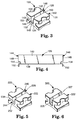
- FIGs. 3 and 4 Another embodiment of the invention is shown in Figs. 3 and 4 and includes a bracket 120 (Fig. 3) having a body 122 somewhat similar to the body 22 shown in Fig. 2, except that the body 122 has a pair of spaced apart gingival tiewings 131 in place of the hook 32. Additionally, a liner 126 of the bracket 120 has end portions 144, 146 that are somewhat different than the end portions 44, 46 described in connection with Figs. 1 and 2.
- a lingual section 152 (Figs. 3-4) of each of the end portions 144, 146 extends flatly over a mesial side 134 and distal side 135 respectively of the bracket body 122 in a direction at a non-zero angle relation to the longitudinal axis of an archwire slot 143.
- the end portions 144, 146 each have an occlusal section 148 and a gingival section 150 that extend parallel to each other and project slightly (e.g., in the range of about .001-.005 inch) past the respective mesial side 134 and distal side 135 in co-planar relation with an occlusal wall 140 (Fig. 4) and a gingival wall 142 (Fig. 3) respectively of a central portion of the liner 126.
- the parallel sections 148, 150 reduce the likelihood of the ceramic body 22 coming into contact with an archwire received in the slot 143.
- Fig. 4 is an illustration of the liner 126 alone.
- the liner 126 is made from an initially flat sheet that is provided with notches 154 to facilitate bending the occlusal wall 140 and the gingival wall 142 relative to a bottom wall 138 to form a substantially rectangular, U-shaped configuration in transverse cross-section.
- the embodiment of the invention that is shown in Fig. 5 concerns a bracket 220 having a body 222 similar to the body 122, and a liner 226 received in a channel of the body 222.
- the liner 226 is essentially identical to the liner 126, except that lingual sections 252 of outwardly extending end portions 244, 246 are coplanar with a bottom wall 238 of the liner 226.
- the bracket 320 that is depicted in Fig. 6 includes a body 322 that is similar to the bodies 122, 222. However, the bracket 320 includes a liner assembly comprised of a mesial liner 325 and a distal liner 327.
- the liner assembly is essentially identical to the liner 26 depicted in Figs. 1 and 2, except that a section of the central portion of the liner 26 has been removed, with the result that the mesial liner 325 is spaced apart from the distal liner 327.
- Fig. 7 is an enlarged, side cross-sectional view of the bracket 20 shown in Fig.2.
- the bottom wall 38, occlusal wall 40 and the gingival wall 42 of the liner 26 are sized to snugly fit within the confines of the channel 24, and also sized to insure that the archwire slot 43 complementally receives a rectangular archwire 47 having cross-sectional dimensions of 0.018 x 0.025 inch.
- Fig. 8 is a view somewhat similar to Fig. 7, in that the dimensions of a channel 24 of a bracket 20a shown in Fig. 8 are identical to the dimensions of the channel 24 shown in Fig. 7. Moreover, outer surfaces of a liner 26a having a bottom wall 38a, an occlusal wall 40a and a gingival wall 42a are sized to snugly fit within the confines of the channel 24. However, the walls 38a, 40a and 42a of the liner 26a are of a somewhat different thickness than the walls 38, 40, 42 of the liner 26 shown in Fig.
- archwire slot 43a is larger in transverse cross-sectional area in comparison to the transverse cross-sectional area of the archwire slot 43 shown in Fig. 7.
- the archwire slot 43a is sized to complementally receive a rectangular archwire 47a having cross-sectional dimensions of 0.022 x 0.028 inch.
- liners 26, 26a having walls of differing thicknesses enable the brackets 20, 20a to be made using identical bracket bodies.
- the liners 26, 26a enable the bodies to snugly receive either of the two sizes of rectangular archwires that are currently in common use, without the necessity of changing the dimensions of the channel 24.
- the channel 24 of both brackets 20, 20a may be cut by a diamond wheel machining process, or molded by an injection molding process, and need not be changed for either of the illustrated brackets 20, 20a.
- the dimensions of the liner 26, 26a are selected to compensate for the differing dimensions of the archwires.
- Such construction may be useful for the manufacturer in reducing the different number of ceramic bracket bodies necessary for inventory, or alternatively may be useful for the orthodontist that desires to replace one liner with another as treatment proceeds to accommodate a differently sized archwire without removing the bracket body 22 from the tooth.
- a bracket 420 includes a body 422 essentially similar to the body 122, and a liner 426 that is received in a channel 424 of the body 422.
- the liner 426 is substantially similar to the liner 126 illustrated in Figs. 3 and 4, except that the liner 426 has a bottom wall 438 provided with a bucco-labially extending protrusion or dimple 456 that is located to one side of a central, occlusal-gingival reference axis of the bracket 420.
- the dimple 456 of the liner 426 contacts a rectangular archwire 458 that is received in an archwire slot 443 of the liner 426, and causes the archwire 458 to extend at an angle inclined in the range of 2 to 5 degrees from a bottom wall 437 of the channel 424.
- the inclination of the archwire 458 enables the latter to assist in rotating the tooth attached to the bracket 420 about the tooth's long axis.
- Occlusal and gingival sides of the archwire 458 flatly contact occlusal and gingival inner surfaces of the liner 426, to enable the archwire 458 to impart tipping or torquing forces when desired to the bracket 420 and the associated tooth according to the treatment technique known as edgewise therapy.
- the embodiment of the invention that is illustrated in Fig. 10 concerns a bracket 520 having a body 522 essentially identical to the body 422.
- a liner 526 is somewhat different than the liner 426 in that a section of the bottom wall 538 near a mesial side 534 of the bracket body 522 is folded over itself.
- the folded-over section of the liner 526 as illustrated in Fig. 10 functions essentially similar to the dimple 456 illustrated in Fig. 9, inasmuch as both features provide a means for enabling an inner, bottom surface 460, 560 of the bottom walls 438, 538 respectively to be located from the bottom channel wall 437, 537 a distance that varies along the length of the archwire slot 443, 543.
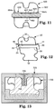
- the bracket 620 illustrated in Fig. 11 has a body 622 somewhat similar to the body 122 illustrated in Fig. 3.
- a channel 624 of the body 622 has a rectangular, U-shaped configuration in transverse cross-section with spaced apart parallel occlusal and gingival walls and a bottom wall that is perpendicular to the occlusal and gingival walls.
- a liner 626 of the bracket 620 includes a central edgewise archwire slot section 662 having parallel occlusal and gingival walls 640, 642 for use in the orthodontic treatment procedure known as edgewise therapy.
- the liner 626 also includes mesial and distal archwire slot relief sections 664a, 664b that provide occlusal and gingival archwire relief.
- the relief sections 664a, 664b are located on mesial and distal sides respectively of the central edgewise archwire slot section 662.
- the configuration of the liner 626 illustrated in Fig. 11 advantageously increases the interbracket distance and provides other advantages such as described in U.S. Patent No. 4,531,911.
- the channel 624 of the bracket body 622 may be readily machined or molded, while the more complex configuration of the edgewise section 662 and the archwire relief sections 664 is provided in the metal liner 626 that is made, for example, by a metal injection molding process or by a metal forming operation.
- the liner 626 is brazed in place by means of brazing material 627.
- the brazing material 627 is received in the space provided between the edgewise archwire slot section 662 and the bracket body 622, so that additional material of the bracket body 622 need not be removed to accommodate the thickness of the brazing material 627.
- the brazing material 627 may extend from the mesial side to the distal side of the bracket body 622.
- the liner 626 and the brazing material 627 extend only along the length of the parallel walls 640, 642 and do not substantially extend into the mesial and distal archwire slot relief sections 664a, 664b.
- Fig. 12 is a front elevational view of the bracket 20 illustrated in Fig. 2, along with a graphite fixture core 66 that is received in the archwire slot 43.
- the graphite fixture core 66 retains the liner 26 firmly in place in the channel 24 as the bracket 20 is placed, for example, in an oven in order to braze the liner 26 to the body 22.
- Fig. 13 is an illustration of a bracket 720 having a liner 726 made in situ by a metal injection molding process.
- the ceramic bracket 720 is placed within a mold assembly 723, and molten metal powder is injected under pressure through a channel 725 in the mold assembly 723 to form the liner 726.
- colloidal metal paints such as Pelco Colloidal Silver from Ted Pella, Inc., Redding, CA
- colloidal metal paints containing glass for improved adhesion such as Heraeus silver metallization paste No.
- the selected in situ process prestresses the ceramic bracket body in the manner mentioned above.
- Paints or pastes may be applied to the bracket body by dipping an archwire in the paint or paste, and then moving the archwire along the channel of the bracket body.
- the archwire slot of the liner may be machined after the liner is formed to ensure that the finished archwire slot has the proper cross-sectional dimensions, although preferably the archwire slot has the desired dimensions upon completion of the in situ process so that the need for subsequent machining is avoided.
Abstract
Description
- This invention relates to a bracket that is used in orthodontic therapy and has an archwire slot liner for enhancing sliding movement of the bracket along an archwire coupled to the bracket.
- In orthodontic treatment, tiny devices known as brackets are secured to the patient's teeth. An archwire is received in a slot of each bracket, and is held in place in the slots by ligating wires or by small elastic O-rings that extend around each bracket and the archwire. The teeth connected to the brackets are urged toward orthodontically correct positions by bends or twists placed in the archwire, or by elastomeric modules interconnecting certain brackets. The archwire serves as a track to guide sliding movement of the brackets so that the associated teeth are shifted toward desired positions.
- In the past, orthodontic brackets were often made of stainless steel, and archwires were made of stainless steel or alloys containing stainless steel, nickel and titanium. In general, frictional resistance to sliding movement of the metal brackets, while not insignificant, is a factor that is not considered unsatisfactory by most orthodontists. However, metal brackets are not aesthetic and are sometimes referred to as a "tin grin" that may be an embarrassment to the patient.
- Orthodontic brackets made of non-opaque plastic materials such as polycarbonate have been introduced by various manufacturers over the years. Unfortunately, some plastic brackets exhibit undue deformation of the archwire slots because of creep of the material as orthodontic forces are applied by the wire to the brackets. Undue deformation of the archwire slots may prevent precise control of movement of the associated teeth, and in some instances may cause the brackets to fracture. Replacement of brackets during orthodontic treatment is time consuming and is often considered a nuisance by the orthodontist as well as by the patient.
- It has been proposed in the past to provide metallic archwire slot liners for plastic brackets, in part as an attempt to avoid deformation of the plastic material. Examples of archwire slot liners are described in U.S. Patent Nos. 3,964,165, 4,299,569 and 4,302,532. Metallic archwire slot liners for plastic brackets provide sliding mechanics that resemble the sliding mechanics as would be observed when an all-metal bracket is used.
- Orthodontic brackets have also been made of translucent ceramic material such as polycrystalline aluminum oxide as is described in U.S. Patent No. 4,954,080, assigned to the assignees of the present invention. Ceramic is a relatively hard material in comparison to plastic and does not exhibit creep deformation in areas adjacent the archwire slot when subjected to forces of the archwire. However, application of an undue force by the archwire may fracture the bracket, possibly because of localized areas of relatively high stress concentrations.
- It has also been observed that the sliding mechanics of a metallic archwire in the slot of a ceramic bracket are not as satisfactory as the sliding mechanics of a metallic wire in the slot of a metal bracket. In one experiment, scanning electron microscope photographs of a stainless steel archwire showed that the archwire had deep scratches after movement along the slot of a ceramic bracket, suggesting that the ceramic material galled the archwire and provided severe mechanical restraint to sliding movement. Unfortunately, undue resistance of a ceramic bracket to sliding movement along an archwire may lengthen treatment time and thus provide an additional expense to both the orthodontist and the patient.
- U.S. Patent No. 3,504,438 proposes an orthodontic bracket made of a stainless steel or chrome alloy and coated with a polymeric material such as polytetrafluoroethylene to provide a relatively low coefficient of friction for sliding movement of the bracket. U.S. Patent No. 5,203,804 (which is assigned to one assignee of the present invention) describes the use of a hard carbon coating such as a diamond-like coating on a metallic orthodontic archwire or on a metallic or ceramic orthodontic bracket.
- The present invention is directed toward a ceramic orthodontic bracket that comprises a ceramic body having an elongated channel. The bracket includes a liner received in the channel and having an archwire slot. The liner is made of a material having a Knoop hardness that is less than the Knoop hardness of the ceramic body. The liner is brazed to the ceramic body.
- The invention is also directed to a method of making a ceramic orthodontic bracket comprising the steps of providing a ceramic orthodontic bracket body having an elongated channel and forming in situ an archwire slot liner in the channel, the liner being made of a material having a Knoop hardness that is less than the Knoop hardness of the ceramic body.
- The invention will be described in detail in connection with the drawings,in which:
- Fig. 1 is a perspective view of a liner for an orthodontic bracket according to one embodiment of the invention;
- Fig. 2 is a perspective view of a bracket having the liner shown in Fig. 1;
- Fig. 3 is a perspective view illustrating a bracket constructed in accordance with another embodiment of the invention;
- Fig. 4 is an enlarged elevational view of the liner alone that is shown in Fig. 3;
- Fig. 5 is a perspective view of a bracket constructed in accordance with another embodiment of the invention;
- Fig. 6 is a perspective view of a bracket in accordance with another embodiment of the invention;
- Fig. 7 is an enlarged side view of an orthodontic bracket of the invention that includes a bracket body having a channel and a liner in the channel with an archwire slot having certain cross-sectional dimensions;
- Fig. 8 is an enlarged side view of a bracket body having a channel with dimensions identical to the channel of the bracket body that is shown in Fig. 7, but with a liner received in the channel having somewhat different cross-sectional dimensions to receive an archwire of a different size;
- Fig. 9 is a fragmentary, enlarged sectional view of an orthodontic bracket made in accordance with another embodiment of the invention, along with an archwire received in an archwire slot of the bracket;
- Fig. 10 is a view somewhat similar to Fig. 9 but constructed in accordance with another embodiment of the invention;
- Fig. 11 is a front view of a bracket having a liner that provides mesial and distal archwire slot relief sections and is held in place by double sided adhesive tape in accordance with another embodiment of the invention;
- Fig. 12 is a reduced front elevational view of the bracket depicted in Fig. 2 along with a graphite fixture core that is placed in an archwire slot of the bracket liner during a brazing operation in order to affix the liner to the bracket body; and
- Fig. 13 is an enlarged side cross-sectional view of a bracket according to another embodiment of the invention, showing a bracket body received in a mold assembly during a metal injection molding process for making the liner.
- An
orthodontic bracket 20 according to one embodiment of the present invention is illustrated in Fig. 2. Thebracket 20 includes aceramic bracket body 22 having anelongated channel 24. Aliner 26 is snugly received in thechannel 24 in mating fashion and is shown alone in Fig. 1. - The
bracket body 22 has abase 28 with a compound contour for attaching thebracket 20 directly to a patient's tooth. A labial face of thebody 22 includes a pair of spaced apartocclusal tiewings gingival hook 32 having mesial and distal notches. Thechannel 24 of thebody 22 extends from amesial side 34 to an opposite,distal side 35 along a central, mesial-distal axis of thebody 22. A pair of opposed,chamfered wall sections 36 are located between the labial face of thebody 22 and thechannel 24 to facilitate insertion of an archwire into theliner 26. - The
liner 26 includes a central portion having abottom wall 38, anocclusal wall 40 and agingival wall 42. Theocclusal wall 40 and thegingival wall 42 are parallel to each other and extend in a direction perpendicular to thebottom wall 38. Thewalls archwire slot 43 having a U-shaped configuration in a longitudinally transverse reference plane. The U-shaped configuration of thearchwire slot 43 matches the cross-sectional shape of a rectangular archwire having similar cross-sectional dimensions, and thus is adapted to complementally receive the archwire in close-fitting relation for orthodontic treatment according to a technique known as edgewise therapy. - The
liner 26 includes amesial end portion 44 and adistal end portion 46 that extend beyond themesial side 34 and thedistal side 35 respectively. Both of theend portions occlusal section 48 extending in an occlusal direction, agingival section 50 extending in a gingival direction, and alingual section 52 extending in a lingual direction. Thesections underlying sides bracket 20 depicted in Figs. 1-2, the mesial anddistal sides archwire slot 43; hence the folded-oversections liner end portions archwire slot 43. However, it is also possible to construct a bracket according to the invention with mesial and distal sides that extend at an angle other than ninety degrees relative to the longitudinal axis of the archwire slot, in which case the folded-over end portions of the liner would also extend at substantially the same, non-ninety degree angle. - The
liner 26 is made of a 0.002 in. (0.05 mm) thick sheet of no. 301 stainless steel, although a gold, titanium or palladium foil sheet may also be utilized. Optionally, theliner 26 is coated with a low friction coating such as the diamond-like coatings that are described in U.S. Patent No. 5,203,804, the disclosure of which is hereby expressly incorporated into the present disclosure. - The
liner 26 is secured in place in thechannel 24 by a brazing process. Suitable brazing filler materials include molybdenum-manganese paste, platinum, silver or an active metal such as titanium or zirconium. Advantageously, thesections mesial side 34 and thedistal side 35, facilitating retention of theliner 26 in thechannel 24. - The
bracket body 22 is made of polycrystalline alumina and has sufficient light transmittance to enable the color of the tooth to be reflected through thebody 22, so that thebody 22 takes on the color of the underlying tooth. Suitable ceramic materials for thebody 22 are described in U.S. Patent No. 4,954,080, the disclosure of which is incorporated by reference herein. In use, most of theliner 26 is positioned behind the archwire and consequently does not significantly lessen the aesthetic nature of thebracket body 22. - The polycrystalline alumina material of the
body 22 is relatively hard and brittle, and typically has a Knoop hardness that is greater than 1200 kg/mm². Advantageously, the material of theliner 26 is relatively soft compared to the material of thebracket body 22, and has a Knoop hardness less than the Knoop hardness of thebody 22. More specifically, theliner 26 has a Knoop hardness in the range of 50-1000 kg/mm², and more preferably in the range of 100-500 kg/mm². The Knoop hardness of theliner 26 is similar to the Knoop hardness of the archwire in order to reduce the likelihood of galling or abrasive wear of the archwire. Theliner 26 also serves to dissipate localized areas of relatively high stress concentrations that might otherwise be imposed by the archwire on thebody 22, thereby reducing the likelihood that thebody 22 will fracture in use. - In one example, an active metal brazing material (Lucanex 721, Lucas-Milhaupt, Inc.) was dispensed into a channel of a polycrystalline alumina bracket body, and a metallic archwire slot liner having a thickness of 0.002 in. (0.05 mm) was inserted into the channel. Excess brazing material was wiped away and a rectangular mandrel having cross-sectional dimensions equivalent to the desired dimensions of the archwire slot was inserted into the liner to assist in maintaining the archwire slot configuration. The assembly of the bracket body, liner and mandrel was then placed in a furnace and heated to 850°C in an argon atmosphere for 12 minutes to braze the liner to the ceramic body before cooling. In another example, a similar bracket body, liner and brazing material were placed in a furnace at 850°C under vacuum for 5 minutes.
- Preferably, the
liner 26 places thebracket body 22 under compressive forces once theliner 26 is secured to thebody 22. In this manner, the relatively brittleceramic body 22 is pre-stressed by theliner 26 and thebracket 20 exhibits superior torque strength in use (i.e., superior resistance to fracture as an archwire is twisted about its long axis) than what might otherwise be observed. Pre-stressing of thebracket body 22 is carried out as thebracket body 22 and theliner 26 are heated during brazing of theliner 26 to thebracket body 22. Upon cooling, the greater thermal contraction of theliner 26 relative to thebracket body 22 enables theliner 26 to thereafter retain the attachedbody 22 under compression. The difference in thermal contraction is due to the fact that the thermal expansion coefficient of theliner 26 is greater than the thermal expansion coefficient of thebracket body 22. - Another embodiment of the invention is shown in Figs. 3 and 4 and includes a bracket 120 (Fig. 3) having a
body 122 somewhat similar to thebody 22 shown in Fig. 2, except that thebody 122 has a pair of spaced apartgingival tiewings 131 in place of thehook 32. Additionally, aliner 126 of thebracket 120 hasend portions end portions - More particularly, a lingual section 152 (Figs. 3-4) of each of the
end portions mesial side 134 anddistal side 135 respectively of thebracket body 122 in a direction at a non-zero angle relation to the longitudinal axis of anarchwire slot 143. However, theend portions occlusal section 148 and agingival section 150 that extend parallel to each other and project slightly (e.g., in the range of about .001-.005 inch) past the respectivemesial side 134 anddistal side 135 in co-planar relation with an occlusal wall 140 (Fig. 4) and a gingival wall 142 (Fig. 3) respectively of a central portion of theliner 126. Theparallel sections ceramic body 22 coming into contact with an archwire received in theslot 143. - Fig. 4 is an illustration of the
liner 126 alone. Theliner 126 is made from an initially flat sheet that is provided withnotches 154 to facilitate bending theocclusal wall 140 and thegingival wall 142 relative to abottom wall 138 to form a substantially rectangular, U-shaped configuration in transverse cross-section. - The embodiment of the invention that is shown in Fig. 5 concerns a
bracket 220 having abody 222 similar to thebody 122, and aliner 226 received in a channel of thebody 222. Theliner 226 is essentially identical to theliner 126, except thatlingual sections 252 of outwardly extendingend portions bottom wall 238 of theliner 226. - The
bracket 320 that is depicted in Fig. 6 includes abody 322 that is similar to thebodies bracket 320 includes a liner assembly comprised of amesial liner 325 and adistal liner 327. The liner assembly is essentially identical to theliner 26 depicted in Figs. 1 and 2, except that a section of the central portion of theliner 26 has been removed, with the result that themesial liner 325 is spaced apart from thedistal liner 327. - Fig. 7 is an enlarged, side cross-sectional view of the
bracket 20 shown in Fig.2. Thebottom wall 38,occlusal wall 40 and thegingival wall 42 of theliner 26 are sized to snugly fit within the confines of thechannel 24, and also sized to insure that thearchwire slot 43 complementally receives arectangular archwire 47 having cross-sectional dimensions of 0.018 x 0.025 inch. - Fig. 8 is a view somewhat similar to Fig. 7, in that the dimensions of a
channel 24 of abracket 20a shown in Fig. 8 are identical to the dimensions of thechannel 24 shown in Fig. 7. Moreover, outer surfaces of aliner 26a having abottom wall 38a, anocclusal wall 40a and agingival wall 42a are sized to snugly fit within the confines of thechannel 24. However, thewalls liner 26a are of a somewhat different thickness than thewalls liner 26 shown in Fig. 7, and are of sufficient thickness such that anarchwire slot 43a is larger in transverse cross-sectional area in comparison to the transverse cross-sectional area of thearchwire slot 43 shown in Fig. 7. Thearchwire slot 43a is sized to complementally receive arectangular archwire 47a having cross-sectional dimensions of 0.022 x 0.028 inch. - Advantageously, and as can be understood by reference to Figs. 7 and 8, the use of
liners brackets liners channel 24. In this manner, thechannel 24 of bothbrackets brackets liner bracket body 22 from the tooth. - Referring now to Fig. 9, a
bracket 420 includes abody 422 essentially similar to thebody 122, and aliner 426 that is received in achannel 424 of thebody 422. Theliner 426 is substantially similar to theliner 126 illustrated in Figs. 3 and 4, except that theliner 426 has abottom wall 438 provided with a bucco-labially extending protrusion ordimple 456 that is located to one side of a central, occlusal-gingival reference axis of thebracket 420. - The
dimple 456 of theliner 426 contacts arectangular archwire 458 that is received in anarchwire slot 443 of theliner 426, and causes thearchwire 458 to extend at an angle inclined in the range of 2 to 5 degrees from abottom wall 437 of thechannel 424. The inclination of thearchwire 458 enables the latter to assist in rotating the tooth attached to thebracket 420 about the tooth's long axis. Occlusal and gingival sides of thearchwire 458 flatly contact occlusal and gingival inner surfaces of theliner 426, to enable thearchwire 458 to impart tipping or torquing forces when desired to thebracket 420 and the associated tooth according to the treatment technique known as edgewise therapy. - The embodiment of the invention that is illustrated in Fig. 10 concerns a
bracket 520 having abody 522 essentially identical to thebody 422. Aliner 526, however, is somewhat different than theliner 426 in that a section of thebottom wall 538 near amesial side 534 of thebracket body 522 is folded over itself. The folded-over section of theliner 526 as illustrated in Fig. 10 functions essentially similar to thedimple 456 illustrated in Fig. 9, inasmuch as both features provide a means for enabling an inner,bottom surface bottom walls bottom channel wall 437, 537 a distance that varies along the length of thearchwire slot - The
bracket 620 illustrated in Fig. 11 has abody 622 somewhat similar to thebody 122 illustrated in Fig. 3. Achannel 624 of thebody 622 has a rectangular, U-shaped configuration in transverse cross-section with spaced apart parallel occlusal and gingival walls and a bottom wall that is perpendicular to the occlusal and gingival walls. - A
liner 626 of thebracket 620 includes a central edgewisearchwire slot section 662 having parallel occlusal andgingival walls liner 626 also includes mesial and distal archwireslot relief sections relief sections archwire slot section 662. - The configuration of the
liner 626 illustrated in Fig. 11 advantageously increases the interbracket distance and provides other advantages such as described in U.S. Patent No. 4,531,911. However, inasmuch as thechannel 624 has essentially straight and parallel walls, thechannel 624 of thebracket body 622 may be readily machined or molded, while the more complex configuration of theedgewise section 662 and the archwire relief sections 664 is provided in themetal liner 626 that is made, for example, by a metal injection molding process or by a metal forming operation. - The
liner 626 is brazed in place by means of brazingmaterial 627. Advantageously, thebrazing material 627 is received in the space provided between the edgewisearchwire slot section 662 and thebracket body 622, so that additional material of thebracket body 622 need not be removed to accommodate the thickness of thebrazing material 627. Alternatively, however, thebrazing material 627 may extend from the mesial side to the distal side of thebracket body 622. As another alternative, theliner 626 and thebrazing material 627 extend only along the length of theparallel walls slot relief sections - Fig. 12 is a front elevational view of the
bracket 20 illustrated in Fig. 2, along with agraphite fixture core 66 that is received in thearchwire slot 43. Thegraphite fixture core 66 retains theliner 26 firmly in place in thechannel 24 as thebracket 20 is placed, for example, in an oven in order to braze theliner 26 to thebody 22. - Fig. 13 is an illustration of a
bracket 720 having aliner 726 made in situ by a metal injection molding process. Theceramic bracket 720 is placed within amold assembly 723, and molten metal powder is injected under pressure through achannel 725 in themold assembly 723 to form theliner 726. - Other in situ processes for forming a liner include the use of colloidal metal paints (such as Pelco Colloidal Silver from Ted Pella, Inc., Redding, CA), colloidal metal paints containing glass for improved adhesion (such as Heraeus silver metallization paste No. C1214B, Heraeus, Inc.), active metal brazing materials (such as titanium, zirconium or Lucanex 721, Lucas-Milhaupt, Inc.), molybdenum-manganese brazing materials, electroless plating processes (using plating materials such as nickel, and optionally followed by conventional electroplating using nickel, copper, gold, or other materials), or vapor phase deposition (such as thermal evaporation, sputtering, ion beam deposition, or chemical vapor deposition). Preferably, the selected in situ process prestresses the ceramic bracket body in the manner mentioned above.
- Paints or pastes may be applied to the bracket body by dipping an archwire in the paint or paste, and then moving the archwire along the channel of the bracket body. The archwire slot of the liner may be machined after the liner is formed to ensure that the finished archwire slot has the proper cross-sectional dimensions, although preferably the archwire slot has the desired dimensions upon completion of the in situ process so that the need for subsequent machining is avoided.
Claims (11)
- A ceramic orthodontic bracket comprising a ceramic body having an elongated channel, said bracket including a liner received in said channel and having an archwire slot, said liner being made of a material having a Knoop hardness that is less than the Knoop hardness of said ceramic body, said liner being brazed to said ceramic body.
- The bracket of claim 1 or 2, wherein said liner is made of a material selected from the group of stainless steel, gold and titanium.
- The bracket of claim 1, wherein said liner is made of a thin metallic foil.
- The bracket of claim 3, wherein said foil comprises stainless steel.
- The bracket of any of clams 1 to 4, including a brazing material selected from the group consisting essentially of platinum, silver, an active metal, a mixture of molybdenum and manganese, or combinations thereof.
- The bracket of claim 5, wherein said brazing material is titanium.
- A method of making a ceramic orthodontic bracket comprising the steps of providing a ceramic orthodontic bracket body having an elongated channel and forming in situ an archwire slot liner in the channel, the liner being made of a material having a Knoop hardness that is less than the Knoop hardness of the ceramic body.
- The method of claim 7, wherein said step of forming in situ an archwire slot liner includes electroless plating.
- The method of claim 7, wherein said step of forming in situ an archwire slot liner includes vapor phase deposition.
- The method of claim 7, wherein said step of forming in situ an archwire slot liner includes brazing.
- The method of any of claims 7 to 10, wherein the liner is made of a colloidal metal paint.
Applications Claiming Priority (2)
| Application Number | Priority Date | Filing Date | Title |
|---|---|---|---|
| US6121593A | 1993-05-13 | 1993-05-13 | |
| US61215 | 1993-05-13 |
Publications (3)
| Publication Number | Publication Date |
|---|---|
| EP0624353A2 true EP0624353A2 (en) | 1994-11-17 |
| EP0624353A3 EP0624353A3 (en) | 1995-04-26 |
| EP0624353B1 EP0624353B1 (en) | 1999-02-24 |
Family
ID=22034381
Family Applications (1)
| Application Number | Title | Priority Date | Filing Date |
|---|---|---|---|
| EP94106862A Expired - Lifetime EP0624353B1 (en) | 1993-05-13 | 1994-05-02 | Ceramic orthodontic bracket with archwire slot liner |
Country Status (3)
| Country | Link |
|---|---|
| US (1) | US5358402A (en) |
| EP (1) | EP0624353B1 (en) |
| DE (1) | DE69416613T2 (en) |
Cited By (7)
| Publication number | Priority date | Publication date | Assignee | Title |
|---|---|---|---|---|
| WO2014128423A2 (en) | 2013-02-23 | 2014-08-28 | Amar Benaddi | Vestibular orthodontic appliance |
| US8944351B2 (en) | 2011-05-06 | 2015-02-03 | Saint-Gobain Abrasives, Inc. | Paint cup assembly with an outlet valve |
| US9162240B2 (en) | 2004-12-16 | 2015-10-20 | Saint-Gobain Abrasives, Inc./Saint-Gobain Abrasie | Liquid container system for a spray gun |
| US9586220B2 (en) | 2011-06-30 | 2017-03-07 | Saint-Gobain Abrasives, Inc. | Paint cup assembly |
| US10035156B2 (en) | 2006-06-20 | 2018-07-31 | Saint-Gobain Abrasives, Inc. | Liquid supply assembly |
| US10882064B2 (en) | 2011-12-30 | 2021-01-05 | Saint-Gobain Abrasives, Inc./Saint-Gobain Abrasifs | Convertible paint cup assembly with air inlet valve |
| US11040360B2 (en) | 2006-06-20 | 2021-06-22 | Saint-Gobain Abrasives, Inc. | Liquid supply assembly |
Families Citing this family (75)
| Publication number | Priority date | Publication date | Assignee | Title |
|---|---|---|---|---|
| JP3364728B2 (en) * | 1994-04-13 | 2003-01-08 | トミー株式会社 | Orthodontic bracket |
| US5597302A (en) * | 1994-10-14 | 1997-01-28 | Minnesota Mining And Manufacturing Company | Aesthetic plastic orthodontic bracket with load bearing framework |
| JP3621737B2 (en) * | 1995-02-17 | 2005-02-16 | トミー株式会社 | Orthodontic bracket |
| US5692896A (en) * | 1995-03-15 | 1997-12-02 | Minnesota Mining And Manufacturing Co. | Light-transmissive orthodontic bracket wth alignment and indentification marking |
| DE19535095A1 (en) * | 1995-09-21 | 1997-03-27 | Foerster Bernhard Gmbh | Metal orthopaedic aid for jaw bone, especially bracket |
| US5816801A (en) * | 1996-10-02 | 1998-10-06 | Ormco Corporation | Insert for reinforcing an orthodontic appliance and method of making same |
| US5769634A (en) * | 1997-06-02 | 1998-06-23 | Choi; John | Dental articulator |
| JP3934207B2 (en) * | 1997-06-13 | 2007-06-20 | デンツプライ三金株式会社 | Bracket with hook |
| ES2154179B1 (en) * | 1998-09-30 | 2001-11-16 | Rainer Brandt | VARIABLE SLOT ORTHODONTIC SUPPORT. |
| AT406636B (en) * | 1998-12-10 | 2000-07-25 | Advanced Prod Inc | Orthodontic component, in particular bracket with an insert element |
| JP3555844B2 (en) | 1999-04-09 | 2004-08-18 | 三宅 正二郎 | Sliding member and manufacturing method thereof |
| US6142775A (en) | 1999-07-14 | 2000-11-07 | 3M Innovative Properties Company | Occlusal cap for orthodontic bracket |
| JP4151813B2 (en) | 1999-07-23 | 2008-09-17 | トミー株式会社 | Orthodontic member and manufacturing method thereof |
| US6302688B1 (en) | 1999-09-27 | 2001-10-16 | 3M Innovative Properties Company | Orthodontic appliance with self-releasing latch |
| US6474988B1 (en) | 2000-03-08 | 2002-11-05 | 3M Innovative Properties Company | Hand instrument for debonding orthodontic brackets |
| JP2002224140A (en) | 2001-02-06 | 2002-08-13 | Tomii Kk | Orthodontic member |
| US6554612B2 (en) | 2001-06-25 | 2003-04-29 | 3M Innovative Properties Company | Orthodontic bracket with recessed attachment and method for making the same |
| JP4135867B2 (en) * | 2001-12-06 | 2008-08-20 | トミー株式会社 | Orthodontics |
| US6878456B2 (en) | 2001-12-28 | 2005-04-12 | 3M Innovative Properties Co. | Polycrystalline translucent alumina-based ceramic material, uses, and methods |
| US6648638B2 (en) | 2001-12-28 | 2003-11-18 | 3M Innovative Properties Company | Orthodontic appliances including polycrystalline alumina-based ceramic material, kits, and methods |
| US6776614B2 (en) | 2002-02-13 | 2004-08-17 | Lingualcare, Inc. | Modular system for customized orthodontic appliances |
| US20040072119A1 (en) * | 2002-06-21 | 2004-04-15 | Orthoarm, Inc. | Self-ligating orthodontic bracket |
| JP2004138128A (en) | 2002-10-16 | 2004-05-13 | Nissan Motor Co Ltd | Sliding member for automotive engine |
| US7695277B1 (en) | 2004-10-28 | 2010-04-13 | Rmo, Inc. | Orthodontic bracket with frangible cover mechanism |
| US7014460B2 (en) * | 2002-11-04 | 2006-03-21 | 3M Innovative Properties Company | Orthodontic appliance with fatigue-resistant archwire retaining latch |
| US6969198B2 (en) | 2002-11-06 | 2005-11-29 | Nissan Motor Co., Ltd. | Low-friction sliding mechanism |
| JP3891433B2 (en) | 2003-04-15 | 2007-03-14 | 日産自動車株式会社 | Fuel injection valve |
| EP1479946B1 (en) | 2003-05-23 | 2012-12-19 | Nissan Motor Co., Ltd. | Piston for internal combustion engine |
| EP1482190B1 (en) | 2003-05-27 | 2012-12-05 | Nissan Motor Company Limited | Rolling element |
| JP2004360649A (en) | 2003-06-06 | 2004-12-24 | Nissan Motor Co Ltd | Piston pin for engine |
| US7318302B2 (en) * | 2003-07-10 | 2008-01-15 | Opperman Investments, Ltd. | Equipment support for a metal building |
| JP4863152B2 (en) | 2003-07-31 | 2012-01-25 | 日産自動車株式会社 | gear |
| KR101003865B1 (en) | 2003-08-06 | 2010-12-30 | 닛산 지도우샤 가부시키가이샤 | Low-Friction Sliding Mechanism, Low-Friction Agent Composition and Method of Friction Reduction |
| JP2005054617A (en) | 2003-08-08 | 2005-03-03 | Nissan Motor Co Ltd | Valve system |
| JP4973971B2 (en) | 2003-08-08 | 2012-07-11 | 日産自動車株式会社 | Sliding member |
| DE602004008547T2 (en) | 2003-08-13 | 2008-05-21 | Nissan Motor Co., Ltd., Yokohama | Structure for connecting a piston to a crankshaft |
| JP4117553B2 (en) | 2003-08-13 | 2008-07-16 | 日産自動車株式会社 | Chain drive |
| US7771821B2 (en) | 2003-08-21 | 2010-08-10 | Nissan Motor Co., Ltd. | Low-friction sliding member and low-friction sliding mechanism using same |
| JP4539205B2 (en) | 2003-08-21 | 2010-09-08 | 日産自動車株式会社 | Refrigerant compressor |
| EP1508611B1 (en) | 2003-08-22 | 2019-04-17 | Nissan Motor Co., Ltd. | Transmission comprising low-friction sliding members and transmission oil therefor |
| US7140876B2 (en) * | 2003-10-31 | 2006-11-28 | 3M Innovative Properties Company | Orthodontic appliance with latch for retaining an archwire |
| US7192274B2 (en) | 2003-12-08 | 2007-03-20 | 3M Innovative Properties Company | Ceramic orthodontic appliance with archwire slot liner |
| US6908240B1 (en) * | 2003-12-16 | 2005-06-21 | International Imaging Materials, Inc | Thermal printing and cleaning assembly |
| US7140875B2 (en) * | 2004-02-03 | 2006-11-28 | 3M Innovative Properties Company | Orthodontic bracket with reinforced tiewings |
| ATE374583T1 (en) * | 2004-03-05 | 2007-10-15 | Straumann Holding Ag | PROCESS OF MANUFACTURING A DENTAL DEVICE USING INJECTION MOLDING |
| US7153130B2 (en) * | 2004-06-10 | 2006-12-26 | 3M Innovative Properties Company | Orthodontic appliance with removable insert |
| US7677887B2 (en) * | 2004-07-02 | 2010-03-16 | Nicholson James A | Shape memory self-ligating orthodontic brackets |
| US20060024634A1 (en) * | 2004-07-28 | 2006-02-02 | 3M Innovative Properties Company | Self-ligating orthodontic appliance with clip |
| US7252505B2 (en) * | 2004-07-28 | 2007-08-07 | 3M Innovative Properties Company | Self-ligating orthodontic appliance with post for connection to a latch |
| JP5437636B2 (en) * | 2005-12-14 | 2014-03-12 | スリーエム イノベイティブ プロパティズ カンパニー | Orthodontic articles coated with zirconium oxide |
| US7377777B2 (en) * | 2005-12-23 | 2008-05-27 | 3M Innovative Properties Company | Orthodontic appliance with archwire-engaging clip |
| JP2009532134A (en) * | 2006-03-31 | 2009-09-10 | アールエムオー,インコーポレイテツド | Orthodontic bracket with liner archwire slot and cover |
| US8979528B2 (en) | 2006-09-07 | 2015-03-17 | Rmo, Inc. | Customized orthodontic appliance method and system |
| US8251697B2 (en) | 2006-09-07 | 2012-08-28 | Rmo, Inc. | Reduced-friction buccal tube and method of use |
| US9554875B2 (en) | 2006-09-07 | 2017-01-31 | Rmo, Inc. | Method for producing a customized orthodontic appliance |
| US8267686B2 (en) * | 2006-09-29 | 2012-09-18 | 3M Innovative Properties Company | Orthodontic bracket with brazed archwire slot liner |
| US7686613B2 (en) * | 2007-07-10 | 2010-03-30 | 3M Innovative Properties Company | Narrow ceramic self-ligating orthodontic bracket |
| WO2010014518A2 (en) | 2008-07-30 | 2010-02-04 | 3M Innovative Properties Company | Low profile self-ligating orthodontic appliance with clip |
| US8585398B2 (en) | 2008-08-13 | 2013-11-19 | Ormco Corporation | Aesthetic orthodontic bracket and method of making same |
| AU2009238317B2 (en) * | 2008-11-14 | 2011-10-06 | Ormco Corporation | Surface treated polycrystalline ceramic orthodontic bracket and method of making same |
| WO2010107567A1 (en) | 2009-03-16 | 2010-09-23 | Rmo, Inc. | Orthodontic bracket having an archwire channel and archwire retaining mechanism |
| US11219507B2 (en) | 2009-03-16 | 2022-01-11 | Orthoamerica Holdings, Llc | Customized orthodontic appliance and method |
| WO2010119880A1 (en) * | 2009-04-16 | 2010-10-21 | 株式会社ジーシー | Orthodontic bracket |
| JP2013538616A (en) | 2010-08-30 | 2013-10-17 | スリーエム イノベイティブ プロパティズ カンパニー | Coated dental article and related manufacturing method |
| EP2706949B1 (en) | 2011-05-12 | 2019-11-13 | Rmo, Inc. | Orthodontic appliance with encoded information formed in the base |
| USD847349S1 (en) | 2011-09-22 | 2019-04-30 | Rmo, Inc. | Orthodontic lock with flange |
| EP2765949A1 (en) | 2011-10-10 | 2014-08-20 | 3M Innovative Properties Company | Orthodontic appliances with tapered archwire slots |
| US9949806B2 (en) | 2013-03-15 | 2018-04-24 | Christopher C. Cosse | Orthodontic bracket assemblies with torque-adjusting drums |
| US10945815B2 (en) | 2013-08-19 | 2021-03-16 | Premier Orthodontics Designs, Lllp | Orthodontic bracket |
| US9198740B2 (en) * | 2013-08-19 | 2015-12-01 | Premier Orthodontic Designs, Lllp | Orthodontic bracket |
| CH709424A2 (en) * | 2014-03-18 | 2015-09-30 | Dr. Med. Dent. Christoph Von Mandach | Kit for an orthodontic bracket. |
| KR101729995B1 (en) * | 2016-06-10 | 2017-05-11 | 주식회사 바이오세텍 | Self ligation orthodontic bracket assembly |
| US10524883B2 (en) | 2016-11-08 | 2020-01-07 | Robert G. Larson | Orthodontic bracket |
| US11376102B2 (en) | 2016-11-08 | 2022-07-05 | Robert G. Larson | Orthodontic bracket |
| USD854163S1 (en) * | 2017-02-09 | 2019-07-16 | Centro de Innovacion en Ortodoncia, S.L. | Dental appliance |
Citations (2)
| Publication number | Priority date | Publication date | Assignee | Title |
|---|---|---|---|---|
| US4302532A (en) * | 1976-06-23 | 1981-11-24 | Melvin Wallshein | Orthodontic bracket with protective insert or liner |
| EP0577398A2 (en) * | 1992-06-30 | 1994-01-05 | JOHNSON & JOHNSON CONSUMER PRODUCTS, INC. | Combination metallic ceramic orthodontic bracket |
Family Cites Families (18)
| Publication number | Priority date | Publication date | Assignee | Title |
|---|---|---|---|---|
| US2908974A (en) * | 1957-12-27 | 1959-10-20 | John J Stifter | Orthodontic attachment |
| US3504438A (en) * | 1966-07-27 | 1970-04-07 | Harold P Wittman | Dental apparatus and methods |
| US3469314A (en) * | 1966-09-14 | 1969-09-30 | Lawrence Pearlman | Orthodontic device |
| US3775850A (en) * | 1971-10-28 | 1973-12-04 | M Northcutt | Orthodontic apparatus |
| US3930311A (en) * | 1973-12-20 | 1976-01-06 | Andrews Lawrence F | Reinforced orthodontic bracket |
| US3964165A (en) * | 1974-05-23 | 1976-06-22 | Stahl Lee W | Elastomeric orthodontic apparatus |
| US4299569A (en) * | 1976-03-08 | 1981-11-10 | Leonard Frantz | Orthodontic bracket for straightening teeth |
| US4107844A (en) * | 1976-11-15 | 1978-08-22 | Kurz Craven H | Orthodontic appliance |
| US4186488A (en) * | 1977-11-11 | 1980-02-05 | Melvin Wallshein | Orthodontic bracket with multi-layer base |
| US4249897A (en) * | 1978-01-17 | 1981-02-10 | Anderson Roland M | Modular cushioning orthodontic bracket structure |
| US4531911A (en) * | 1983-12-05 | 1985-07-30 | Creekmore Thomas D | Combination single/twin edgewise orthodontic bracket |
| DE3588089T2 (en) * | 1984-04-23 | 1996-10-02 | Johnson & Johnson Dental Prod | Orthodontic bracket made of crystalline aluminum oxide |
| CA1326382C (en) * | 1986-05-08 | 1994-01-25 | John Steven Kelly | Ceramic orthodontic appliance |
| US4674978A (en) * | 1986-06-04 | 1987-06-23 | Raul Acevedo | Orthodontic appliance |
| US4850865A (en) * | 1987-04-30 | 1989-07-25 | Napolitano John R | Orthodontic method and apparatus |
| US5018259A (en) * | 1988-09-21 | 1991-05-28 | Wildman Alexander J | Method of design and manufacture of laminated orthodontic brackets |
| US5203804A (en) * | 1991-07-18 | 1993-04-20 | Minnesota Mining And Manufacturing Company | Coated dental article |
| US5252066A (en) * | 1992-08-28 | 1993-10-12 | Johnson & Johnson Consumer Products, Inc. | Orthodontic bracket formed from porcelain fused to metallic material |
-
1993
- 1993-10-25 US US08/142,836 patent/US5358402A/en not_active Expired - Lifetime
-
1994
- 1994-05-02 DE DE69416613T patent/DE69416613T2/en not_active Expired - Lifetime
- 1994-05-02 EP EP94106862A patent/EP0624353B1/en not_active Expired - Lifetime
Patent Citations (2)
| Publication number | Priority date | Publication date | Assignee | Title |
|---|---|---|---|---|
| US4302532A (en) * | 1976-06-23 | 1981-11-24 | Melvin Wallshein | Orthodontic bracket with protective insert or liner |
| EP0577398A2 (en) * | 1992-06-30 | 1994-01-05 | JOHNSON & JOHNSON CONSUMER PRODUCTS, INC. | Combination metallic ceramic orthodontic bracket |
Cited By (12)
| Publication number | Priority date | Publication date | Assignee | Title |
|---|---|---|---|---|
| US9162240B2 (en) | 2004-12-16 | 2015-10-20 | Saint-Gobain Abrasives, Inc./Saint-Gobain Abrasie | Liquid container system for a spray gun |
| US10035156B2 (en) | 2006-06-20 | 2018-07-31 | Saint-Gobain Abrasives, Inc. | Liquid supply assembly |
| US11040360B2 (en) | 2006-06-20 | 2021-06-22 | Saint-Gobain Abrasives, Inc. | Liquid supply assembly |
| US11548018B1 (en) | 2006-06-20 | 2023-01-10 | Saint-Gobain Abrasives, Inc. | Liquid supply assembly |
| US11679399B2 (en) | 2006-06-20 | 2023-06-20 | Saint-Gobain Abrasives, Inc. | Liquid supply assembly |
| US8944351B2 (en) | 2011-05-06 | 2015-02-03 | Saint-Gobain Abrasives, Inc. | Paint cup assembly with an outlet valve |
| US8998018B2 (en) | 2011-05-06 | 2015-04-07 | Saint-Gobain Abrasives, Inc. | Paint cup assembly with an extended ring |
| US9335198B2 (en) | 2011-05-06 | 2016-05-10 | Saint-Gobain Abrasives, Inc. | Method of using a paint cup assembly |
| US9586220B2 (en) | 2011-06-30 | 2017-03-07 | Saint-Gobain Abrasives, Inc. | Paint cup assembly |
| US10882064B2 (en) | 2011-12-30 | 2021-01-05 | Saint-Gobain Abrasives, Inc./Saint-Gobain Abrasifs | Convertible paint cup assembly with air inlet valve |
| WO2014128423A2 (en) | 2013-02-23 | 2014-08-28 | Amar Benaddi | Vestibular orthodontic appliance |
| EP3308737A1 (en) | 2013-02-23 | 2018-04-18 | Amar Benaddi | Vestibular orthodontic appliance |
Also Published As
| Publication number | Publication date |
|---|---|
| DE69416613T2 (en) | 1999-07-08 |
| EP0624353B1 (en) | 1999-02-24 |
| EP0624353A3 (en) | 1995-04-26 |
| DE69416613D1 (en) | 1999-04-01 |
| US5358402A (en) | 1994-10-25 |
Similar Documents
| Publication | Publication Date | Title |
|---|---|---|
| EP0624353B1 (en) | Ceramic orthodontic bracket with archwire slot liner | |
| EP0624354B1 (en) | Orthodontic bracket with archwire slot liner | |
| EP0679074B1 (en) | Coated dental article | |
| EP1778122B1 (en) | Self-ligating orthodontic appliance with post for connection to a latch | |
| US6299438B1 (en) | Orthodontic articles having a low-friction coating | |
| EP1843716B1 (en) | Pre-torqued orthodontic appliance with archwire retaining latch | |
| EP1401349B1 (en) | Orthodontic bracket with recessed attachment and method for making the same | |
| EP1796574B1 (en) | Self-ligating orthodontic appliance with clip | |
| US7192274B2 (en) | Ceramic orthodontic appliance with archwire slot liner | |
| US20120322019A1 (en) | Customized Orthodontic Arch Wire Manufactured Using Model of Patient's Teeth | |
| EP1962714B1 (en) | Orthodontic appliance with archwire-engaging clip | |
| US20040086825A1 (en) | Orthodontic appliance with fatigue-resistant archwire retaining latch | |
| WO2006094403A1 (en) | Self-ligating orthodontic bracket | |
| JP2002524132A (en) | Low rigidity orthodontic arch wire | |
| WO2010068286A1 (en) | Bracket with improved arch wire slot liner | |
| US20130017506A1 (en) | Orthodontic device | |
| EP2068749B1 (en) | Orthodontic bracket with brazed archwire slot liner | |
| US5395237A (en) | Orthodontic bracket with integral ball hook and method of making | |
| EP3745993B1 (en) | Ceramic self-ligating bracket with high labial pull strength | |
| JP3588140B2 (en) | Ceramic orthodontic bracket with archwire slot liner | |
| JP2003180712A (en) | Orthodontic bracket | |
| WO1998014527A1 (en) | Metal to ceramic attachment in dental appliances |
Legal Events
| Date | Code | Title | Description |
|---|---|---|---|
| PUAI | Public reference made under article 153(3) epc to a published international application that has entered the european phase |
Free format text: ORIGINAL CODE: 0009012 |
|
| AK | Designated contracting states |
Kind code of ref document: A2 Designated state(s): DE FR GB IT |
|
| PUAL | Search report despatched |
Free format text: ORIGINAL CODE: 0009013 |
|
| AK | Designated contracting states |
Kind code of ref document: A3 Designated state(s): DE FR GB IT |
|
| 17P | Request for examination filed |
Effective date: 19951013 |
|
| GRAG | Despatch of communication of intention to grant |
Free format text: ORIGINAL CODE: EPIDOS AGRA |
|
| 17Q | First examination report despatched |
Effective date: 19980409 |
|
| GRAG | Despatch of communication of intention to grant |
Free format text: ORIGINAL CODE: EPIDOS AGRA |
|
| GRAG | Despatch of communication of intention to grant |
Free format text: ORIGINAL CODE: EPIDOS AGRA |
|
| GRAH | Despatch of communication of intention to grant a patent |
Free format text: ORIGINAL CODE: EPIDOS IGRA |
|
| GRAH | Despatch of communication of intention to grant a patent |
Free format text: ORIGINAL CODE: EPIDOS IGRA |
|
| GRAA | (expected) grant |
Free format text: ORIGINAL CODE: 0009210 |
|
| AK | Designated contracting states |
Kind code of ref document: B1 Designated state(s): DE FR GB IT |
|
| REF | Corresponds to: |
Ref document number: 69416613 Country of ref document: DE Date of ref document: 19990401 |
|
| ET | Fr: translation filed | ||
| ITF | It: translation for a ep patent filed |
Owner name: ING. C. GREGORJ S.P.A. |
|
| PLBE | No opposition filed within time limit |
Free format text: ORIGINAL CODE: 0009261 |
|
| STAA | Information on the status of an ep patent application or granted ep patent |
Free format text: STATUS: NO OPPOSITION FILED WITHIN TIME LIMIT |
|
| 26N | No opposition filed | ||
| REG | Reference to a national code |
Ref country code: GB Ref legal event code: IF02 |
|
| PGFP | Annual fee paid to national office [announced via postgrant information from national office to epo] |
Ref country code: GB Payment date: 20120502 Year of fee payment: 19 |
|
| PGFP | Annual fee paid to national office [announced via postgrant information from national office to epo] |
Ref country code: DE Payment date: 20130515 Year of fee payment: 20 |
|
| PGFP | Annual fee paid to national office [announced via postgrant information from national office to epo] |
Ref country code: FR Payment date: 20130531 Year of fee payment: 20 Ref country code: IT Payment date: 20130515 Year of fee payment: 20 |
|
| GBPC | Gb: european patent ceased through non-payment of renewal fee |
Effective date: 20130502 |
|
| PG25 | Lapsed in a contracting state [announced via postgrant information from national office to epo] |
Ref country code: GB Free format text: LAPSE BECAUSE OF NON-PAYMENT OF DUE FEES Effective date: 20130502 |
|
| REG | Reference to a national code |
Ref country code: DE Ref legal event code: R071 Ref document number: 69416613 Country of ref document: DE |
|
| REG | Reference to a national code |
Ref country code: DE Ref legal event code: R071 Ref document number: 69416613 Country of ref document: DE |
|
| PG25 | Lapsed in a contracting state [announced via postgrant information from national office to epo] |
Ref country code: DE Free format text: LAPSE BECAUSE OF EXPIRATION OF PROTECTION Effective date: 20140503 |