EP0614311A1 - IIR ghost cancelling system - Google Patents
IIR ghost cancelling system Download PDFInfo
- Publication number
- EP0614311A1 EP0614311A1 EP94102883A EP94102883A EP0614311A1 EP 0614311 A1 EP0614311 A1 EP 0614311A1 EP 94102883 A EP94102883 A EP 94102883A EP 94102883 A EP94102883 A EP 94102883A EP 0614311 A1 EP0614311 A1 EP 0614311A1
- Authority
- EP
- European Patent Office
- Prior art keywords
- weighting coefficients
- signal
- sum
- iir filter
- scaling
- Prior art date
- Legal status (The legal status is an assumption and is not a legal conclusion. Google has not performed a legal analysis and makes no representation as to the accuracy of the status listed.)
- Granted
Links
Images

Classifications
-
- H—ELECTRICITY
- H04—ELECTRIC COMMUNICATION TECHNIQUE
- H04N—PICTORIAL COMMUNICATION, e.g. TELEVISION
- H04N5/00—Details of television systems
- H04N5/14—Picture signal circuitry for video frequency region
- H04N5/21—Circuitry for suppressing or minimising disturbance, e.g. moiré or halo
-
- H—ELECTRICITY
- H04—ELECTRIC COMMUNICATION TECHNIQUE
- H04N—PICTORIAL COMMUNICATION, e.g. TELEVISION
- H04N5/00—Details of television systems
- H04N5/14—Picture signal circuitry for video frequency region
- H04N5/21—Circuitry for suppressing or minimising disturbance, e.g. moiré or halo
- H04N5/211—Ghost signal cancellation
Definitions
- This invention relates to ghost cancelling systems which employ infinite impulse response (IIR) filters, and more particularly to apparatus for providing stable operation of the IIR filters in such system.
- IIR infinite impulse response
- Ghost cancelling systems nominally consist of two parts, a programmable filter and circuitry for calculating a model of the signal transmission channel.
- the channel modelling circuitry is responsive to a transmitted reference signal and a stored idealized reference signal for determining the characteristics of the transmission channel (in particular characteristics which may give rise to multipath distortion). From such characteristics, the channel modelling circuitry generates coefficients for programming the programmable filter to pass video signal with multipath distortion substantially eliminated.
- the programmable filters are typically of two types, finite impulse response (FIR) and infinite impulse response (IIR). Some ghost cancelling systems employ FIR filters, others employ IIR filters, but the majority of systems use a combination of both.
- FIR finite impulse response
- IIR infinite impulse response
- Both the IIR and FIR ghost cancelling filters employ tapped delay lines providing a plurality of relatively delayed signals.
- the delayed signals are weighted by programmable coefficients, and the weighted coefficients are combined to provide a filtered output signal.
- the FIR and IIR filters have relative advantages and disadvantages but it is well known that FIR filters are inherently stable, and that IIR filters give rise to stability problems.
- the present invention is directed toward ameliorating instabilities in ghost cancelling systems which use IIR type ghost cancelling filters.
- the present invention is a ghost cancelling system including a ghost cancelling IIR filter and channel modelling circuitry for generating tap weighting coefficients for programming the ghost cancelling IIR filter.
- the channel modelling circuitry includes means for calculating the sum of all of the generated weighting coefficient values. If the sum exceeds a predetermined value indicative of the IIR filter becoming unstable, the weighting coefficients are conditionally scaled in a manner to reduce the sum, thus tending to reduce the possibility of filter instability.
- FIGURE 1 is a block diagram of a ghost cancelling system incorporating the present invention.
- FIGURE 2 is a logic diagram of a two's complement overflow detector which may be implemented in the FIGURE 1 apparatus.
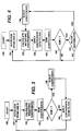
- FIGURES 3 and 4 are representative flow charts of the operation of the FIGURE 1 system.
- weighting coefficient generating apparatus consist of special purpose programmable microprocessors, which may be programmed to perform a variety of algebraic functions. Therefore it is presumed that it will be a simple exercise for one skilled in the art of implementing weighting coefficient generating apparatus, to further program such apparatus to perform simple arithmetic manipulations on the weighting coefficients once generated.
- the elements 10-18 comprise the basic structure of known ghost cancelling systems which utilize IIR ghost cancelling filters.
- Input signal is applied to bus 10 from for example an antenna/tuner combination.
- the input signal is coupled to a channel modelling and control element 18, which is responsive to a ghost cancelling reference signal included at regular predetermined intervals in the input signal for generating weighting coefficients to be applied to the ghost cancelling filter.
- the ghost cancelling filter consists of the adder 12, the tapped delay line 14, the plurality of weighting circuits 15 and the adder 16.
- the input signal is applied to the adder 12 which has an output coupled to the input of the tapped delay line.
- Relatively delayed replicas of the signal input to the delay line are accessed at the respective taps and weighted by coefficient values generated by the channel modelling element 18.
- the weighted replicas are summed in the adder 16, and the resultant sum is applied to the second input connection of the adder 12.
- the signal from adder 16 applied to the second input of the adder 12 will include a compliment of signal components necessary to cancel any multipath distortion included in the input signal.
- the adder 12 may in fact be realized with a subtracter. Whether element 12 is realized as an adder or subtracter is dependent upon the relative polarities assigned to the respective weighting coefficients.
- IIR ghost cancelling filters if the magnitudes of all of the weighting coefficients applied to the ghost cancelling IIR filter sum to a value greater than one, the filter may be unstable.
- stability may be predicted by factoring the filter transfer function and determining if any Z-plane poles have magnitudes greater than zero. The stability is also dependent in part on the variable dynamic range of the input signal and the fixed dynamic range of the processing apparatus. In a television system the dynamic range of received television signals differ from channel to channel, hence a IIR ghost cancelling filter may be unstable for one channel but not another.
- the ghost cancelling IIR filter is made unconditionally stable.
- the channel modelling and control apparatus is arranged to operate according to the flow chart illustrated in FIGURE 3.
- the channel modelling and control apparatus responsive to horizontal and vertical synchronizing components of the input video signal obtains [101] the ghost cancelling reference (GCR) signal contained in line 21 of the video signal.
- GCR ghost cancelling reference
- the magnitudes of the weighting coefficients are summed [103] and the resultant sum is compared [104] to the value one.
- the weighting coefficients are applied [105] to the respective weighting circuits in the IIR filter. If the sum is greater than one, the respective weighting coefficients are scaled [106] to lessen the sum of coefficients.
- the scaling factor may be of the form 1/( ⁇ S) where S is the sum of weighting coefficients and ⁇ is a factor one or less but close to one e.g., 0.95.
- the factor ⁇ may be made dependent upon the value of S, and selected such that ⁇ S is not less than a predetermined value e.g., 1.1. After the weighting coefficients have been scaled, they are applied [105] to the respective weighting circuits in the filter.
- the weighting coefficients may be complex valued if the ghost cancelling filter is arranged to process quadrature components of the input signal.
- the magnitudes of the complex components may be summed to simplify the hardware requirements.
- the sum of the coefficients is given by; Using this value for the sum imposes a stricter bound, since it will always exceed the sum of the actual magnitudes
- the filter is not necessarily unstable. If it is not unstable and the coefficients are scaled, ghost cancellation will be somewhat impaired. Therefore, when the sum of weighting coefficients exceed the value one, it is desirable to scale these coefficients only if the filter will exhibit unstable tendencies.
- the weighting coefficients are used to program the filter even if their sum exceeds the value one, and then the filter is tested for instability, and if an indication of instability is detected, the coefficients are scaled. Operation in this mode is represented by the flow chart of FIGURE 4. It is to be noted that the operation indicated in FIGURE 4 allows for the iterative incremental scaling of the coefficients until filter instabilities disappear.
- the FIGURE 1 apparatus includes an over/underflow detector 20.
- the over/underflow detector generates an output signal indicative of over/underflows, which output signal is coupled to the channel modelling and control circuitry 18.
- circuitry 18 may be arranged to automatically scale the weighting coefficients if their sum exceeds a predetermined value greater than one, and to conditionally scale the weighting coefficients in accordance with over/underflow detection if the sum of coefficients is greater than one but less than said predetermined value.
- the adder 16 may also exhibit over/underflows of partial sums. However these over/underflows will not affect filter stability. Hence it is not necessary to monitor this adder for over/underflows to insure filter stability. However over/underflows exhibited within the adder 16 may affect the accuracy of ghost cancelling performance. Thus for superior system performance it is desirable to monitor the adder 16 for the occurrence of over/underflows, and responsive thereto scale the weighting coefficients. In this instance the scale factor may be different than the scale factor used when the adder 12 over/underflows.
- Figure 2 shows an exemplary over/underflow detector which may be implemented for two's complement number systems.
- This circuitry is responsive to the sign-bits of the samples applied to the input of the adder and the sign-bit of the result provided by the adder.
- An overflow occurs when two positive input values produce a negative output value and an underflow occurs when two negative input values produce a positive output value.
- the occurrence of these two conditions is detected with two AND gates (30, 32) and one OR gate 33.
- positive numbers have logic zero sign-bits and negative numbers have logic one sign-bits.
- Detection of the overflow condition is performed by the AND gate 32 having the output sign-bit of the adder connected to its non-inverting input and the two input sign-bits of the adder connected to respective inverting inputs.
- detection of the underflow condition is performed by the second AND gate 30 having the output sign-bit of the adder connected to its inverting input and the two input sign-bits of the adder connected to respective non-inverting inputs.
- the AND gates 32 and 30 will exhibit logic high levels at their respective output connections only on the occurrence of an overflow and an underflow respectively.
- the output connections of the AND gates 30 and 32 are coupled to respective input connections of the OR gate 33, which provides a composite over/underflow detection signal at its output connection.
- the over/underflow signal provided by the OR gate 33 may be directly coupled to the circuitry 18 to control coefficient scaling. However single occurrences of over/underflows may not accurately indicate filter instability. Therefore it is desirable to process the output of the OR gate 33 before application to the circuit 18.
- One example of over/underflow signal processing is shown in figure 2.
- the output of the OR gate 33 is coupled to the count input of a binary counter 34.
- a vertical synchronizing signal is coupled to a reset control of the counter and resets the count value to zero at the beginning of each field interval.
- the counter 34 thus counts the number of occurrences of over/underflows each field period.
- the more significant output bits of the counter 34 are coupled to respective input connections of an OR gate 35, i.e., bits 23-26.
- the Or gate 35 provides the over/underflow' output signal whenever there are 8 or more over/underflow indications provided by the OR gate 33 in a field interval.
- Another example of over/underflow signal processing may include providing an over/underflow'' signal only after the occurrence of a predetermined number of over/underflow indications for consecutive samples per field interval.
Abstract
Description
- This invention relates to ghost cancelling systems which employ infinite impulse response (IIR) filters, and more particularly to apparatus for providing stable operation of the IIR filters in such system.
- Ghost cancelling systems nominally consist of two parts, a programmable filter and circuitry for calculating a model of the signal transmission channel. The channel modelling circuitry is responsive to a transmitted reference signal and a stored idealized reference signal for determining the characteristics of the transmission channel (in particular characteristics which may give rise to multipath distortion). From such characteristics, the channel modelling circuitry generates coefficients for programming the programmable filter to pass video signal with multipath distortion substantially eliminated. For a more detailed description of channel modelling techniques see U.S. Patent 4,864,403, issued Sept. 5, 1989 and titled "Adaptive Television Ghost Cancellation System Including Filter Circuitry with Non-Integer Sample Delay" or GHOST REDUCTION BY REPRODUCTION by N. Komlya, IEEE Transactions on Consumer Electronics, Aug. 1992, Vol. 38, No. 3, pp. 195-199, for example. The programmable filters are typically of two types, finite impulse response (FIR) and infinite impulse response (IIR). Some ghost cancelling systems employ FIR filters, others employ IIR filters, but the majority of systems use a combination of both.
- Both the IIR and FIR ghost cancelling filters employ tapped delay lines providing a plurality of relatively delayed signals. The delayed signals are weighted by programmable coefficients, and the weighted coefficients are combined to provide a filtered output signal. The FIR and IIR filters have relative advantages and disadvantages but it is well known that FIR filters are inherently stable, and that IIR filters give rise to stability problems. The present invention is directed toward ameliorating instabilities in ghost cancelling systems which use IIR type ghost cancelling filters.
- The present invention is a ghost cancelling system including a ghost cancelling IIR filter and channel modelling circuitry for generating tap weighting coefficients for programming the ghost cancelling IIR filter. The channel modelling circuitry includes means for calculating the sum of all of the generated weighting coefficient values. If the sum exceeds a predetermined value indicative of the IIR filter becoming unstable, the weighting coefficients are conditionally scaled in a manner to reduce the sum, thus tending to reduce the possibility of filter instability.
- FIGURE 1 is a block diagram of a ghost cancelling system incorporating the present invention.
- FIGURE 2 is a logic diagram of a two's complement overflow detector which may be implemented in the FIGURE 1 apparatus.
- FIGURES 3 and 4 are representative flow charts of the operation of the FIGURE 1 system.
- Apparatus for generating weighting coefficients for ghost cancelling systems are relatively well known by those persons skilled in the art of video signal processing, and thus such apparatus will not be described here in detail. Suffice it to say that typical weighting coefficient generating apparatus consist of special purpose programmable microprocessors, which may be programmed to perform a variety of algebraic functions. Therefore it is presumed that it will be a simple exercise for one skilled in the art of implementing weighting coefficient generating apparatus, to further program such apparatus to perform simple arithmetic manipulations on the weighting coefficients once generated.
- Referring to FIGURE 1, the elements 10-18 comprise the basic structure of known ghost cancelling systems which utilize IIR ghost cancelling filters. Input signal is applied to
bus 10 from for example an antenna/tuner combination. The input signal is coupled to a channel modelling andcontrol element 18, which is responsive to a ghost cancelling reference signal included at regular predetermined intervals in the input signal for generating weighting coefficients to be applied to the ghost cancelling filter. The ghost cancelling filter consists of theadder 12, the tappeddelay line 14, the plurality ofweighting circuits 15 and theadder 16. The input signal is applied to theadder 12 which has an output coupled to the input of the tapped delay line. Relatively delayed replicas of the signal input to the delay line are accessed at the respective taps and weighted by coefficient values generated by thechannel modelling element 18. The weighted replicas are summed in theadder 16, and the resultant sum is applied to the second input connection of theadder 12. Assuming the weighting coefficients were accurately calculated, the signal fromadder 16 applied to the second input of theadder 12 will include a compliment of signal components necessary to cancel any multipath distortion included in the input signal. It is to be noted that since the signal fed back from theadder 16 is arranged to cancel components in the input signal, theadder 12 may in fact be realized with a subtracter. Whetherelement 12 is realized as an adder or subtracter is dependent upon the relative polarities assigned to the respective weighting coefficients. - It has been found for IIR ghost cancelling filters, that if the magnitudes of all of the weighting coefficients applied to the ghost cancelling IIR filter sum to a value greater than one, the filter may be unstable. For filters with clocked delay elements stability may be predicted by factoring the filter transfer function and determining if any Z-plane poles have magnitudes greater than zero. The stability is also dependent in part on the variable dynamic range of the input signal and the fixed dynamic range of the processing apparatus. In a television system the dynamic range of received television signals differ from channel to channel, hence a IIR ghost cancelling filter may be unstable for one channel but not another.
- In a first embodiment of the invention the ghost cancelling IIR filter is made unconditionally stable. In this embodiment the channel modelling and control apparatus is arranged to operate according to the flow chart illustrated in FIGURE 3. The channel modelling and control apparatus, responsive to horizontal and vertical synchronizing components of the input video signal obtains [101] the ghost cancelling reference (GCR) signal contained in
line 21 of the video signal. Using the received GCR and a stored ideal version of the GCR, it calculates [102] the weighting coefficients for programming the ghost cancelling IIR filter to eliminate ghosts in the channel currently being received. The magnitudes of the weighting coefficients are summed [103] and the resultant sum is compared [104] to the value one. If the sum is less than one, the weighting coefficients are applied [105] to the respective weighting circuits in the IIR filter. If the sum is greater than one, the respective weighting coefficients are scaled [106] to lessen the sum of coefficients. The scaling factor may be of theform 1/(αS) where S is the sum of weighting coefficients and α is a factor one or less but close to one e.g., 0.95. The factor α may be made dependent upon the value of S, and selected such that αS is not less than a predetermined value e.g., 1.1. After the weighting coefficients have been scaled, they are applied [105] to the respective weighting circuits in the filter. - The weighting coefficients may be complex valued if the ghost cancelling filter is arranged to process quadrature components of the input signal. In this instance the magnitudes of the complex components may be summed to simplify the hardware requirements. Assume that the coefficients C, are of the form

The sum of the coefficients is given by;
Using this value for the sum imposes a stricter bound, since it will always exceed the sum of the actual magnitudes |xi+jyi|. - As mentioned above, merely because the sum of the magnitudes of the weighting coefficients exceeds one, the filter is not necessarily unstable. If it is not unstable and the coefficients are scaled, ghost cancellation will be somewhat impaired. Therefore, when the sum of weighting coefficients exceed the value one, it is desirable to scale these coefficients only if the filter will exhibit unstable tendencies. The weighting coefficients are used to program the filter even if their sum exceeds the value one, and then the filter is tested for instability, and if an indication of instability is detected, the coefficients are scaled. Operation in this mode is represented by the flow chart of FIGURE 4. It is to be noted that the operation indicated in FIGURE 4 allows for the iterative incremental scaling of the coefficients until filter instabilities disappear.
- One method for detecting unstable tendencies in the IIR filter is to monitor the
adder 12 for output overflows or underflows. Overflows and underflows occur, in two's complement arrangements for example, if two like polarity sample values applied to the input connections of an adder, sum to a value which is greater than the output bits of the adder can represent. The FIGURE 1 apparatus includes an over/underflow detector 20. The over/underflow detector generates an output signal indicative of over/underflows, which output signal is coupled to the channel modelling andcontrol circuitry 18. Thecircuitry 18, responsive to the signal indicative of over/underflows, scales the generated weighting coefficients to lessen the sum of the magnitudes of the weighting coefficients. Note that thecircuitry 18 may be arranged to automatically scale the weighting coefficients if their sum exceeds a predetermined value greater than one, and to conditionally scale the weighting coefficients in accordance with over/underflow detection if the sum of coefficients is greater than one but less than said predetermined value. - The
adder 16 may also exhibit over/underflows of partial sums. However these over/underflows will not affect filter stability. Hence it is not necessary to monitor this adder for over/underflows to insure filter stability. However over/underflows exhibited within theadder 16 may affect the accuracy of ghost cancelling performance. Thus for superior system performance it is desirable to monitor theadder 16 for the occurrence of over/underflows, and responsive thereto scale the weighting coefficients. In this instance the scale factor may be different than the scale factor used when theadder 12 over/underflows. - Figure 2 shows an exemplary over/underflow detector which may be implemented for two's complement number systems. This circuitry is responsive to the sign-bits of the samples applied to the input of the adder and the sign-bit of the result provided by the adder. An overflow occurs when two positive input values produce a negative output value and an underflow occurs when two negative input values produce a positive output value. The occurrence of these two conditions is detected with two AND gates (30, 32) and one
OR gate 33. In two's complement number systems, positive numbers have logic zero sign-bits and negative numbers have logic one sign-bits. Detection of the overflow condition is performed by the ANDgate 32 having the output sign-bit of the adder connected to its non-inverting input and the two input sign-bits of the adder connected to respective inverting inputs. Similarly detection of the underflow condition is performed by the second ANDgate 30 having the output sign-bit of the adder connected to its inverting input and the two input sign-bits of the adder connected to respective non-inverting inputs. The ANDgates gates OR gate 33, which provides a composite over/underflow detection signal at its output connection. - The over/underflow signal provided by the
OR gate 33 may be directly coupled to thecircuitry 18 to control coefficient scaling. However single occurrences of over/underflows may not accurately indicate filter instability. Therefore it is desirable to process the output of theOR gate 33 before application to thecircuit 18. One example of over/underflow signal processing is shown in figure 2. In this example the output of theOR gate 33 is coupled to the count input of abinary counter 34. A vertical synchronizing signal is coupled to a reset control of the counter and resets the count value to zero at the beginning of each field interval. Thecounter 34 thus counts the number of occurrences of over/underflows each field period. The more significant output bits of thecounter 34 are coupled to respective input connections of anOR gate 35, i.e., bits 2³-2⁶. TheOr gate 35 provides the over/underflow' output signal whenever there are 8 or more over/underflow indications provided by theOR gate 33 in a field interval. Another example of over/underflow signal processing may include providing an over/underflow'' signal only after the occurrence of a predetermined number of over/underflow indications for consecutive samples per field interval.
Claims (9)
- Multipath signal cancelling apparatus characterized by:
a source of input signal (10);
a programmable IIR filter (12-16) including signal summing means (12) for combining said input signal and output signal provided by said IIR filter, said IIR filter having a plurality of weighting circuits (15) with respective input connections for receiving weighting coefficients;
channel modelling means (18), responsive to said input signal for generating said weighting coefficients, said channel modelling means including means for providing a sum of the magnitudes of the generated weighting coefficients and means for scaling said weighting coefficients to reduce said sum if said sum exceeds a predetermined value; and
means for applying scaled weighting coefficients to said programmable IIR filter. - The apparatus set forth in claim 1 characterized in that said predetermined value is greater than one.
- The apparatus set forth in claim 1 characterized in that said means for scaling said weighting coefficients includes means coupled to said IIR filter for detecting potential IIR filter instabilities, and performing scaling of the weighting coefficients if potential filter instabilities are detected.
- The apparatus set forth in claim 3 characterized in that said means for detecting IIR filter instabilities includes a signal overflow detector coupled to said signal summing means.
- The apparatus set forth in claim 4 characterized in that said signal overflow detector includes means for processing signal indicating signal overflows such that scaling of weighting coefficients is initiated only on the occurrence of predetermined overflow conditions.
- The apparatus set forth in claim 1 characterized in that said means for scaling includes means for generating a scaling factor proportional to the reciprocal of the sum of the weighting coefficients.
- Multipath signal cancelling apparatus characterized by:
a source of input video signal (10);
a programmable IIR filter (12-16) including signal summing means (12) for combining said input video signal and output signal provided by said IIR filter, said IIR filter having a plurality of weighting circuits (15) with respective input connections for receiving weighting coefficients;
channel modelling means (18), responsive to said input video signal, for generating said weighting coefficients;
means (20) coupled to said signal summing means for generating an overflow signal OVF indicating occurrences of the dynamic range of said signal summing means being exceeded;
detecting means (18) responsive to said overflow signal OVF, for scaling the generated weighting coefficients such that the sum of the magnitudes of the scaled weighting coefficients is less than the sum of the magnitudes of the non-scaled weighting coefficients, when the dynamic range of the summing means is exceeded; and
means for substituting said scaled weighting coefficients for said weighting coefficients. - The apparatus set forth in claim 7 characterized in that said means for detecting includes means for processing said overflow signal OVF such that scaling of weighting coefficients is initiated only after the dynamic range of the summing means is exceeded a predetermined number of times per predetermined interval.
- The apparatus set forth in claim 7 characterized in that said means for scaling includes means for generating a scaling factor proportional to the reciprocal of the sum of the weighting coefficients.
Applications Claiming Priority (2)
| Application Number | Priority Date | Filing Date | Title |
|---|---|---|---|
| US25496 | 1993-03-03 | ||
| US08/025,496 US5335020A (en) | 1993-03-03 | 1993-03-03 | IIR ghost cancelling system with reduction of filter instability |
Publications (2)
| Publication Number | Publication Date |
|---|---|
| EP0614311A1 true EP0614311A1 (en) | 1994-09-07 |
| EP0614311B1 EP0614311B1 (en) | 1999-08-25 |
Family
ID=21826418
Family Applications (1)
| Application Number | Title | Priority Date | Filing Date |
|---|---|---|---|
| EP94102883A Expired - Lifetime EP0614311B1 (en) | 1993-03-03 | 1994-02-25 | IIR ghost cancelling system |
Country Status (11)
| Country | Link |
|---|---|
| US (1) | US5335020A (en) |
| EP (1) | EP0614311B1 (en) |
| JP (1) | JP3578793B2 (en) |
| KR (1) | KR100290194B1 (en) |
| CN (1) | CN1043109C (en) |
| DE (1) | DE69420162T2 (en) |
| MY (1) | MY110395A (en) |
| RU (1) | RU2119267C1 (en) |
| SG (1) | SG82534A1 (en) |
| TR (1) | TR27397A (en) |
| TW (1) | TW245856B (en) |
Families Citing this family (7)
| Publication number | Priority date | Publication date | Assignee | Title |
|---|---|---|---|---|
| US6128539A (en) * | 1994-08-30 | 2000-10-03 | Texas Instruments Incorporated | Method and apparatus for forming image scaling filters |
| US5623319A (en) * | 1995-10-05 | 1997-04-22 | Philips Electronics North American Corp. | Ghost cancellation reference signal detection and synchronization circuit |
| US6377308B1 (en) * | 1996-06-26 | 2002-04-23 | Intel Corporation | Method and apparatus for line-specific decoding of VBI scan lines |
| US5974363A (en) * | 1997-04-09 | 1999-10-26 | Lucent Technologies Inc. | Self-testing of smart line cards |
| US5905659A (en) * | 1997-10-07 | 1999-05-18 | Rose; Ralph E. | Training a recursive filter by use of derivative function |
| EP1575176A1 (en) * | 2004-03-09 | 2005-09-14 | Deutsche Thomson-Brandt Gmbh | Arrangement for adaptive bit recovery |
| US7746924B2 (en) * | 2006-05-09 | 2010-06-29 | Hewlett-Packard Development Company, L.P. | Determination of filter weights |
Citations (6)
| Publication number | Priority date | Publication date | Assignee | Title |
|---|---|---|---|---|
| US3609568A (en) * | 1970-06-08 | 1971-09-28 | Bell Telephone Labor Inc | Stable digital filter apparatus |
| JPS57185727A (en) * | 1981-05-12 | 1982-11-16 | Victor Co Of Japan Ltd | Rejector for waveform distortion |
| JPS59198020A (en) * | 1983-04-25 | 1984-11-09 | Sony Corp | Digital signal processor |
| WO1989007376A1 (en) * | 1988-02-08 | 1989-08-10 | Rca Licensing Corporation | Adaptive television ghost cancellation system |
| EP0413460A2 (en) * | 1989-08-17 | 1991-02-20 | Kabushiki Kaisha Toshiba | Ghost cancelling system and method of controlling such a system |
| EP0467338A2 (en) * | 1990-07-17 | 1992-01-22 | Nec Corporation | Ghost cancelling circuit |
Family Cites Families (9)
| Publication number | Priority date | Publication date | Assignee | Title |
|---|---|---|---|---|
| US4127874A (en) * | 1976-05-27 | 1978-11-28 | Tokyo Shibaura Electric Co., Ltd. | Apparatus for removing ghost signals from received video signals |
| JPS56100579A (en) * | 1980-01-12 | 1981-08-12 | Sony Corp | Ghost eliminating device |
| JPS575441A (en) * | 1980-06-13 | 1982-01-12 | Sony Corp | Ghost rejecting device |
| JPS5745778A (en) * | 1980-09-02 | 1982-03-15 | Fujitsu Ltd | Automatic waveform equalizer for television signal |
| JPS58101576A (en) * | 1981-12-11 | 1983-06-16 | Sony Corp | Ghost eliminating device |
| JPS59211388A (en) * | 1983-05-17 | 1984-11-30 | Toshiba Corp | Ghost eliminating device |
| JPS59214386A (en) * | 1983-05-19 | 1984-12-04 | Sony Corp | Ghost eliminating device |
| JPH03123276A (en) * | 1989-10-06 | 1991-05-27 | Toshiba Corp | Ghost image removing device |
| JPH03145281A (en) * | 1989-10-30 | 1991-06-20 | Toshiba Corp | Ghost elimination device |
-
1993
- 1993-03-03 US US08/025,496 patent/US5335020A/en not_active Expired - Lifetime
-
1994
- 1994-02-23 TW TW083101563A patent/TW245856B/zh active
- 1994-02-25 DE DE69420162T patent/DE69420162T2/en not_active Expired - Fee Related
- 1994-02-25 MY MYPI94000457A patent/MY110395A/en unknown
- 1994-02-25 SG SG9602466A patent/SG82534A1/en unknown
- 1994-02-25 EP EP94102883A patent/EP0614311B1/en not_active Expired - Lifetime
- 1994-03-01 RU RU94006781A patent/RU2119267C1/en not_active IP Right Cessation
- 1994-03-02 KR KR1019940003951A patent/KR100290194B1/en not_active IP Right Cessation
- 1994-03-02 TR TR00193/94A patent/TR27397A/en unknown
- 1994-03-02 CN CN94101297A patent/CN1043109C/en not_active Expired - Fee Related
- 1994-03-02 JP JP03264494A patent/JP3578793B2/en not_active Expired - Fee Related
Patent Citations (7)
| Publication number | Priority date | Publication date | Assignee | Title |
|---|---|---|---|---|
| US3609568A (en) * | 1970-06-08 | 1971-09-28 | Bell Telephone Labor Inc | Stable digital filter apparatus |
| JPS57185727A (en) * | 1981-05-12 | 1982-11-16 | Victor Co Of Japan Ltd | Rejector for waveform distortion |
| JPS59198020A (en) * | 1983-04-25 | 1984-11-09 | Sony Corp | Digital signal processor |
| WO1989007376A1 (en) * | 1988-02-08 | 1989-08-10 | Rca Licensing Corporation | Adaptive television ghost cancellation system |
| US4864403A (en) * | 1988-02-08 | 1989-09-05 | Rca Licensing Corporation | Adaptive television ghost cancellation system including filter circuitry with non-integer sample delay |
| EP0413460A2 (en) * | 1989-08-17 | 1991-02-20 | Kabushiki Kaisha Toshiba | Ghost cancelling system and method of controlling such a system |
| EP0467338A2 (en) * | 1990-07-17 | 1992-01-22 | Nec Corporation | Ghost cancelling circuit |
Non-Patent Citations (2)
| Title |
|---|
| PATENT ABSTRACTS OF JAPAN vol. 7, no. 33 (E - 157) 9 February 1983 (1983-02-09) * |
| PATENT ABSTRACTS OF JAPAN vol. 9, no. 56 (E - 302) 12 March 1985 (1985-03-12) * |
Also Published As
| Publication number | Publication date |
|---|---|
| TW245856B (en) | 1995-04-21 |
| TR27397A (en) | 1995-02-28 |
| KR100290194B1 (en) | 2001-05-15 |
| JPH06303463A (en) | 1994-10-28 |
| RU2119267C1 (en) | 1998-09-20 |
| SG82534A1 (en) | 2001-08-21 |
| US5335020A (en) | 1994-08-02 |
| KR940023176A (en) | 1994-10-22 |
| DE69420162T2 (en) | 1999-12-09 |
| MY110395A (en) | 1998-04-30 |
| CN1102924A (en) | 1995-05-24 |
| JP3578793B2 (en) | 2004-10-20 |
| DE69420162D1 (en) | 1999-09-30 |
| CN1043109C (en) | 1999-04-21 |
| EP0614311B1 (en) | 1999-08-25 |
Similar Documents
| Publication | Publication Date | Title |
|---|---|---|
| EP0437861B1 (en) | Signal processing method and system. | |
| US5398029A (en) | Sampling rate converter | |
| US4682230A (en) | Adaptive median filter system | |
| EP0196825A2 (en) | Scaling circuitry with truncation offset compensation | |
| US4507725A (en) | Digital filter overflow sensor | |
| US5335020A (en) | IIR ghost cancelling system with reduction of filter instability | |
| EP0137816A1 (en) | Apparatus for generating scaled weighting coefficients for sampled data filters | |
| Butler et al. | Noniterative automatic equalization | |
| US4750146A (en) | Method and apparatus for compensating for the truncation error in a filtered signal by adding the error to the positive part of the signal and subtracting the error from the negative part of the signal | |
| EP0559154B1 (en) | Digital filter | |
| US4511922A (en) | Digital television system with truncation error correction | |
| EP0791242B1 (en) | Improved digital filter | |
| US6058404A (en) | Apparatus and method for a class of IIR/FIR filters | |
| EP0384445B1 (en) | Arithmetic unit using a digital filter | |
| JPH08317254A (en) | Ghost elimination device | |
| JP2538633B2 (en) | Adaptive filter | |
| JPH0346813A (en) | Digital filter circuit | |
| US7340020B2 (en) | Method and apparatus for tracking invalid signals through a digital system | |
| JPH06181424A (en) | Digital filter system | |
| US6757702B1 (en) | Adaptive filter | |
| KR0152343B1 (en) | Arithmatic correction circuit of digital transform coder | |
| KR100292476B1 (en) | Circuit and method for reducing deghosting error of tv | |
| KR100224689B1 (en) | Apparatus and method for reducing image with high resolution | |
| JP2775887B2 (en) | Digital filter for fault current measurement of power system. | |
| JPH02288675A (en) | Ghost eliminating device |
Legal Events
| Date | Code | Title | Description |
|---|---|---|---|
| PUAI | Public reference made under article 153(3) epc to a published international application that has entered the european phase |
Free format text: ORIGINAL CODE: 0009012 |
|
| AK | Designated contracting states |
Kind code of ref document: A1 Designated state(s): DE FR GB IT |
|
| 17P | Request for examination filed |
Effective date: 19950209 |
|
| 17Q | First examination report despatched |
Effective date: 19970318 |
|
| GRAG | Despatch of communication of intention to grant |
Free format text: ORIGINAL CODE: EPIDOS AGRA |
|
| GRAG | Despatch of communication of intention to grant |
Free format text: ORIGINAL CODE: EPIDOS AGRA |
|
| GRAH | Despatch of communication of intention to grant a patent |
Free format text: ORIGINAL CODE: EPIDOS IGRA |
|
| GRAH | Despatch of communication of intention to grant a patent |
Free format text: ORIGINAL CODE: EPIDOS IGRA |
|
| GRAA | (expected) grant |
Free format text: ORIGINAL CODE: 0009210 |
|
| AK | Designated contracting states |
Kind code of ref document: B1 Designated state(s): DE FR GB IT |
|
| ET | Fr: translation filed | ||
| REF | Corresponds to: |
Ref document number: 69420162 Country of ref document: DE Date of ref document: 19990930 |
|
| ITF | It: translation for a ep patent filed |
Owner name: ING. C. GREGORJ S.P.A. |
|
| PLBE | No opposition filed within time limit |
Free format text: ORIGINAL CODE: 0009261 |
|
| STAA | Information on the status of an ep patent application or granted ep patent |
Free format text: STATUS: NO OPPOSITION FILED WITHIN TIME LIMIT |
|
| 26N | No opposition filed | ||
| REG | Reference to a national code |
Ref country code: GB Ref legal event code: 732E |
|
| REG | Reference to a national code |
Ref country code: GB Ref legal event code: IF02 |
|
| REG | Reference to a national code |
Ref country code: FR Ref legal event code: D6 |
|
| REG | Reference to a national code |
Ref country code: GB Ref legal event code: 746 Effective date: 20030228 |
|
| PGFP | Annual fee paid to national office [announced via postgrant information from national office to epo] |
Ref country code: IT Payment date: 20080226 Year of fee payment: 15 Ref country code: GB Payment date: 20080129 Year of fee payment: 15 Ref country code: DE Payment date: 20080221 Year of fee payment: 15 |
|
| PGFP | Annual fee paid to national office [announced via postgrant information from national office to epo] |
Ref country code: FR Payment date: 20080218 Year of fee payment: 15 |
|
| GBPC | Gb: european patent ceased through non-payment of renewal fee |
Effective date: 20090225 |
|
| REG | Reference to a national code |
Ref country code: FR Ref legal event code: ST Effective date: 20091030 |
|
| PG25 | Lapsed in a contracting state [announced via postgrant information from national office to epo] |
Ref country code: DE Free format text: LAPSE BECAUSE OF NON-PAYMENT OF DUE FEES Effective date: 20090901 |
|
| PG25 | Lapsed in a contracting state [announced via postgrant information from national office to epo] |
Ref country code: GB Free format text: LAPSE BECAUSE OF NON-PAYMENT OF DUE FEES Effective date: 20090225 Ref country code: FR Free format text: LAPSE BECAUSE OF NON-PAYMENT OF DUE FEES Effective date: 20090302 |
|
| PG25 | Lapsed in a contracting state [announced via postgrant information from national office to epo] |
Ref country code: IT Free format text: LAPSE BECAUSE OF NON-PAYMENT OF DUE FEES Effective date: 20090225 |