EP0614105A2 - Contact lens for correcting of astigmatism - Google Patents
Contact lens for correcting of astigmatism Download PDFInfo
- Publication number
- EP0614105A2 EP0614105A2 EP94108668A EP94108668A EP0614105A2 EP 0614105 A2 EP0614105 A2 EP 0614105A2 EP 94108668 A EP94108668 A EP 94108668A EP 94108668 A EP94108668 A EP 94108668A EP 0614105 A2 EP0614105 A2 EP 0614105A2
- Authority
- EP
- European Patent Office
- Prior art keywords
- lens
- zone
- base curve
- toric
- curve
- Prior art date
- Legal status (The legal status is an assumption and is not a legal conclusion. Google has not performed a legal analysis and makes no representation as to the accuracy of the status listed.)
- Granted
Links
Images


Classifications
-
- G—PHYSICS
- G02—OPTICS
- G02C—SPECTACLES; SUNGLASSES OR GOGGLES INSOFAR AS THEY HAVE THE SAME FEATURES AS SPECTACLES; CONTACT LENSES
- G02C7/00—Optical parts
- G02C7/02—Lenses; Lens systems ; Methods of designing lenses
- G02C7/04—Contact lenses for the eyes
-
- G—PHYSICS
- G02—OPTICS
- G02C—SPECTACLES; SUNGLASSES OR GOGGLES INSOFAR AS THEY HAVE THE SAME FEATURES AS SPECTACLES; CONTACT LENSES
- G02C7/00—Optical parts
- G02C7/02—Lenses; Lens systems ; Methods of designing lenses
- G02C7/04—Contact lenses for the eyes
- G02C7/048—Means for stabilising the orientation of lenses in the eye
Definitions
- Astigmatism is a defect in the eye that is corrected by a lens with a non-spherical prescription.
- the prescription which is usually expressed as cylinder on the patient's prescription order, causes at least a portion of the surface of the lens to have the shape of a toric segment.
- Such lenses are called toric lenses.
- the corrective lens must be properly oriented with respect to the eye of the wearer. That is, the intended top of the lens must be at the top of the wearer's eye. For ordinary glasses this presents no problem, because the lens is permanently fixed to the frame at the correct rotational orientation.
- the ear and nose pieces of the frame assure that the frame and the lens do not rotate with respect to the wearer's eyes.
- For contact lenses orientation is subject to constant alteration. In the case of contact lenses whose function is to correct astigmatism this is unacceptable.
- Soft contact lenses which have been designed for use to correct astigmatism are well known in the art. Generally these lenses rely on some type of ballasting method to cause the lens to ride at the proper location on the eye.
- An ideal lens for correcting astigmatism has three properties:
- Lenses in accordance with this invention are preferably soft contact lenses, which may be formed of many materials including hydroxyethylmethacrylate, metallo-organic substances, silicone rubbers and various other materials such as described in U.S. Patent Nos. 3,503,942 and 3,639,524.
- the preferred soft contact lenses are hydrophilic; that is, they absorb water and, in fact, the water becomes an integral part of their structure. Hydrophilic contact lenses made in accordance with U.S. Patent No. 4,405,773 are especially preferred for practicing this invention.
- U.S. Patent No. 4,084,890 discloses a contact lens which is alleged to have improved adherence to the cornea and improved visual acuity as a result of its configuration.
- the lens tapers from a thin outer edge to an intermediate point of maximum thickness and then tapers to the center of the lens.
- the peripheral surface portion is wedge shaped in cross section.
- this lens is believed to be uncomfortable because of its thickness.
- U.S. Patent No. 4,095,8708 discloses a contact lens which maintains the correct orientation when placed on the eye as a result of a flattened portion on the periphery.
- the lens is symmetrical about the horizontal axis.
- the lens is thinnest at its vertical axis and increases in thickness along the flattened section in both directions from the vertical axis, having its thickest portion at the horizontal axis. While the disclosed lens has rotational stability, the lens of the present invention is expected to have better rotational stability.
- U.S. Patent No. 4,324,461 discloses a contact lens for correcting astigmatism which is alleged to provide the proper rotational positioning.
- the lens has a thickness disparity between the superior (top) and inferior (bottom) portions of the lens and a thicker ballast portion is provided at the inferior portion.
- the thicker ballast portion of the lens is believed to cause discomfort compared to the lens of the present invention.
- the posterior surface of a contact lens is generally spherical in configuration, where the lens is to used to correct astigmatism it will have a toric configuration. That is, the curved portion of the posterior of the lens has a major and minor axis; the radius of curvature of the posterior surface of the lens being longer in the major-axis direction than in the minor-axis direction.
- the posterior of the lens has a toric configuration with the major axis running orthogonal to the minor axis.
- the major diameter of the toric curve is generally smaller in diameter than the overall lens, and is cut into a starting base curve which has a spherical configuration.
- the junction between the base curve of the posterior surface of the lens and the toric curve portion is in an area of sharp inflection resulting in a sometimes uncomfortable fit to the cornea.
- a contact lens of improved rotational stability, rotational orientation and comfort can be prepared by configuring the lens so that it has a greater thickness in its lower portion, the lens being symmetrical about its vertical axis on its anterior surface.
- the comfort to the wearer of the lens is improved by having a gradual change in curvature between the base curve portion of the posterior of the lens and the toric curve.
- a first aspect of the invention may be summarized as a contact lens of general concavo-convex configuration having improved rotational stabilization and rotational orientation
- the anterior surface of said lens comprises a central optical zone and an outer carrier having a generally tapered surface with a thin portion at the upper edge of the lens and two points of maximum thickness located at oblige angels ⁇ of about 110° to 130° as measured from the vertical axis of the lens; the anterior surface of the lens being symmetrical about the vertical axis, the carrier tapering from the points of maximum thickness to a thin portion located at the top of the lens and to a thin portion located at the lower edge of the lens in a smooth curve.
- a second aspect of the invention may be summarized as a contact lens for correcting astigmatism of general concavo-convex configuration having a posterior surface comprising:
- the lens has the anterior surface of the first aspect and the posterior surface of the second aspect.
- the invention is especially suitable for hydrophilic contact lens which are normally shaped in the dry state and then hydrated. Upon hydration, such lenses expand. All deminsions given in the specification and claims are for a full sized lens; i.e., for a hydrophilic lens, a fully hydrated lens; unless specifically stated to be for a lens in the dry state.
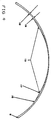
- Figure 1 is a view of the anterior surface of the lens.
- Figure 2 is a sectional view of the lens of figure 1 taken along section A-C, wherein the portion of section A-C from the lens center to C has been rotated so that A-C is a straight line.
- Figure 3 is a sectional view of the lens showing its anterior surface taken along the major axis of the lens's toric curve.
- Figure 4 is a sectional view of the lens showing its anterior surface taken along the minor axis of the lens's toric curve.
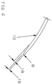
- Figure 5 is a view of the posterior surface of the lens.
- Figure 6 is s sectional view of the edge of the lens of this invention showing details of an optional edge configuration.
- vertical is used with reference to the lens as it would be, if ideally seated on the cornea of eye without any shift in orientation resulting by movement caused by the eye lid.
- the vertical axis is represented in Figure 1 by the center line A-A.
- the lens 1 has a central optical zone, 2, which is formed by known prior art techniques.
- the optical zone is surrounded by a carrier portion as in the prior art.
- the configuration of this carrier portion of the lens differs from the prior art as hereinafter described.
- Curves 3, 4 and 5 represent portions of the surface of the carrier portion as formed in the manner described below, to form the anterior surface of the lens. While these curves appear to delineate distinct areas of the lens they are shown for clarity of description of the invention only. It will be appreciated by those skilled in the art that there are no sharp distinctions between these different sections of the carrier portion of the lens, but that they are smoothly blended into one another.
- the thickest portion of the lens is located at points, 6 and 6'. All references to point, 6, are applicable to point, 6', since the lens is symmetrical about center line A-A on its anterior surface. Point, 6, is located on the center line B-C at the intersection of curves 3,4 and 5. It is located on a line along center line B-C at an angle, ⁇ , from the vertical.
- the angle, ⁇ is the included angle designated by the bent lines A-C and A-C'.
- the angle, ⁇ should be about 110° to about 130°; more preferably about 115° to about 125°; most preferably 120°.
- the angle, ⁇ is measured from the top of the lens which is at 0°.
- Figure 2 is a sectional view along Section A-C ( Figure 1) showing the anterior surface of the lens.
- Figure 2 shows the view that would be seen if line A-C of figure 1 were to be straightened.
- the anterior surface of the inventive lens is formed by first rotating it about central axis, O-O, to cut a concentric trim, 7.
- the concentric trim, 7, results in a thinner edge section of the lens with more comfort to the wearer.
- the term "concentric trim” means the aforedescribed concentric thinned section of the lens. It is an optional improvement in the lens of this invention, but where it is utilized, it is the first section cut. The cutting is accomplished by the prior art technique of swinging the cutting tool through a fixed circular arc while rotating the lens.
- the concentric trim as it appears in the finished lens, is located between the outer edge 8 of the lens and curves 3 and 4 (see Figure 1).
- the lower portion 100 of the carrier of the lens is then cut by shifting the axis of the lens along the vertical center line, A-A ( Figure 2), a distance, a, to the position shown by rotation axis, K-K displaced toward the upper section of the lens.
- Rotation about Axis K-K while cutting generates the lower portion 100 of the carrier which tapers in a smooth curve along vertical axis AA from the optical zone to the bottom of the lens, as best seem in figure 1.
- the axis of the lens is then shifted along the vertical center line, A-A, a distance, b, from the central axis, O-O, toward the lower portion of the lens to a new axis of rotation, I-I, to cut the upper section 101 of the carrier.
- ⁇ 90°
- a 0.1 to about 0.4 mm
- a is about 0.2 to about 1.2 mm
- the optical zone, 2 is cut in the manner of the prior art. It is usually spherical in configuration, but it can have a toric configuration. The radius of curvature will depend on the prescription of the user. All of the axes of rotation including that used to cut the optical zone are on the vertical center line A-A.
- a base curve is cut into the posterior surface of the lens.
- this base curve is constructed of two distinct zones, a sphenial base curve zone 11 and a pad zone 10.
- the pad zone is made up of pad curve 13 and a transition zone 9.
- the radius of the base curve zone 11 on an outer annulus of the lens is approximately equal to the radius that the toric section of the lens is to have along its major meridian. This is much different from the prior art wherein the radius of the base curve, which initially extends over the entire anterior surface of the prior art lens is longer than the radius which the toric section is to have in its major meridian.
- Pad curve 13 is cut into the lens at a radius that is smaller than the radius of base curve zone 11 by about 0.08 to 0.15 mm, preferably 0.1 mm. Curves 13 and 11 have the same center of curative. Transition zone 9 is about 0.5 to 1.5 mm wide, and in cross section is essentially a linear ramp connecting base curve zone 11 with pad curve 10. Curves 13 and 9 are both spherical. Thus the thickness of the transition zone generally increases from base curve zone 11 to pad curve 13.
- this toric curve has a major and minor axis.
- the radius of curvature of the major curve of the major meridian is generally the same as that of the base curve zone 11.
- This major median of the toric curve may lie on vertical line A-A ( Figure 5). However, alternatively, it may be an an oblique angle to that line depending on the users prescription or the rotation of the lens resulting from movement caused by the eye lid, or both.
- the depth of cut is controlled so that it intersects the transition zone 9 near its outer edge, 12, as best seen in figure 5 along axis A-A.
- the outer edge of the transition zone, 12, is the outer edge of the pad zone 10.
- the major meridian 15 of the toric curve will be slightly smaller than the outer dimension of the pad zone.
- the major meridian of the toric curve is about 0.03 to 0.5 mm smaller than the pad zone diameter.
- the minor meridian, 15', of the toric curve which is at right angles to the major meridian and may lie on line E-E, is less than the pad zone diameter by about 0.2 to about 2.5 mm.
- Figure 4 is a sectional view showing he posterior lens configuration taken along the minor axis of the toric curve, i.e. along section E-E of figure 5.
- the outer edge 17 of the minor axis can be seen, as well as the edge 16 of the pad zone, and pad curve 13.
- This configuration results in a smoother blend between the transition zone 9 and toric curve 14 as contrasted with the prior art which has a steeper inflection point between the toric curve and the base curve.
- the intersection of the minor meridian 17 and transition zone 9 is located no more than 0.12 mm below an imaginary extension of spherical base curve zone 11 passing above that intersection. Preferably this intersection will be between 0.04 and 0.12mm below the imaginary extension of the spherical base curve zone. Furthermore, the intersection of the major axis 15 and transition zone 9 will be located no more than 0.07 mm below an imaginary extension of spherical base curve zone 9. For prescription, wherein the outer edge of the toric curve at the major meridian and the outer edge of transition zone 9 coincide, the intersection will be located on spherical base curve zone 9.
- the configuration of the posterior of the lens of this invention results in a lens which along its vertical meridian is thinner at the junction of the carrier with the optical zone than prior art lenses and thus is thinner in the carrier as a whole. This results in a lens which on average is lighter in weight.
- Prior art lenses are about 0.18 mm in thickness in the dry state at their thickest point along the vertical meridian.
- the lenses of this invention will range in maximum thickness from about 0.13 to about 0.15 in the dry state at the corresponding point.
- the intersection of the outer edge of the toric curve with the transition zone is more obtuse than that between the toric curve and the base curve of the prior art.
- the more obtuse junction contributes to greater lens comfort, and lessens the possibility that the lens will make a pressure indentation on the corneal surface. This contributes both to comfort because of reduced weight, and to improved oxygen transmissibility of the lens, thereby improving corneal health.
- the edge thickness 19 of the lens as shown in Figure 6, is about 0.03 to about 0.11 mm.
- This edge optionally, is displaced from the base curve zone, 10, by an edge lift, 18, of about 0.05 to about 0.12 mm.
- the effect of the lift is to give a more comfortable feel to the wearer of the lens.
- the edge thickness, 19, of the lens of this invention as measured at the edge of the lens, 8, is generally thinner than that of the prior art as a result of the concentric trim, previously described.
- the configuration of the anterior of the lens and the base curve as well as the pad of the posterior of the lens can be formed by molding the lens in an appropriately shaped cavity mold.
- a contact lens of general concavo-convex configuration having improved rotational stability and rotational orientation wherein the anterior surface of said lens comprises a central optical zone and an outer carrier having a generally tapered surface with a thin portion at the upper edge of the lens and two points of maximum thickness located at oblique angles, ⁇ , of about 110° to about 130° as measured from the vertical axis from the top of the lens; the anterior surface of said lens being symmetrical about the vertical axis, the carrier tapering from the points of maximum thickness to a thin portion located at the top of the lens and to a thin portion located at the lower edge of the lens in a smooth curve, and the carrier tapering in a smooth curve along the vertical axis from the optical zone to the bottom of the lens.
- the contact lens according to the above wherein the angle, ⁇ , is about 115° to about 125°.
- a contact lens for correcting astigmatism of general concavo-convex configuration having a posterior surface comprising:
- the anterior surface comprises a central optical zone and an outer carrier having a generally tapered surface with a thin portion at the upper edge of the lens and two points of maximum thickness located at an oblique angle ⁇ of about 110° to about 130° as measured from the vertical axis from the top of the lens, said anterior surface being symmetrical about its vertical axis, the carrier tapering from the points of maximum thickness to a thin portion located at the top of the lens and to a thin portion located at the lower edge of the lens in a smooth curve.
- the contact lens of the above wherein the maximum thickness of the lens is located on radii at points about 0.7 to 1.5 mm from the edge of the lens.
- the lens of the above wherein the angle ⁇ is about 115° to 125°.
Abstract
Description
- Astigmatism is a defect in the eye that is corrected by a lens with a non-spherical prescription. The prescription, which is usually expressed as cylinder on the patient's prescription order, causes at least a portion of the surface of the lens to have the shape of a toric segment. Hence, such lenses are called toric lenses. The corrective lens must be properly oriented with respect to the eye of the wearer. That is, the intended top of the lens must be at the top of the wearer's eye. For ordinary glasses this presents no problem, because the lens is permanently fixed to the frame at the correct rotational orientation. The ear and nose pieces of the frame assure that the frame and the lens do not rotate with respect to the wearer's eyes. For contact lenses orientation is subject to constant alteration. In the case of contact lenses whose function is to correct astigmatism this is unacceptable.
- Soft contact lenses which have been designed for use to correct astigmatism are well known in the art. Generally these lenses rely on some type of ballasting method to cause the lens to ride at the proper location on the eye. An ideal lens for correcting astigmatism has three properties:
- (1) Good rotational orientation. That is, as stated above, the intended top of the lens should be located at the top of the wearer's eye when the lens is worn. A small amount of deviation from the correct orientation can be tolerated, provided the lens fitter measures the deviation and takes it into account in the lens's prescription.
- (2) Good rotational stability. That is, the lens should remain at a fixed rotational orientation within the eye during the entire wearing period. Furthermore, the lens should assume the same orientation each time it is worn.
- (3) Comfort. In general the thinner the lens and the smoother the lens surface, the more comfort it will provide.
- Lenses in accordance with this invention are preferably soft contact lenses, which may be formed of many materials including hydroxyethylmethacrylate, metallo-organic substances, silicone rubbers and various other materials such as described in U.S. Patent Nos. 3,503,942 and 3,639,524. The preferred soft contact lenses are hydrophilic; that is, they absorb water and, in fact, the water becomes an integral part of their structure. Hydrophilic contact lenses made in accordance with U.S. Patent No. 4,405,773 are especially preferred for practicing this invention.
- U.S. Patent No. 4,084,890, discloses a contact lens which is alleged to have improved adherence to the cornea and improved visual acuity as a result of its configuration. The lens tapers from a thin outer edge to an intermediate point of maximum thickness and then tapers to the center of the lens. The peripheral surface portion is wedge shaped in cross section. However this lens is believed to be uncomfortable because of its thickness.
- U.S. Patent No. 4,095,878, discloses a contact lens which maintains the correct orientation when placed on the eye as a result of a flattened portion on the periphery. In one embodiment the lens is symmetrical about the horizontal axis. The lens is thinnest at its vertical axis and increases in thickness along the flattened section in both directions from the vertical axis, having its thickest portion at the horizontal axis. While the disclosed lens has rotational stability, the lens of the present invention is expected to have better rotational stability.
- U.S. Patent No. 4,324,461, discloses a contact lens for correcting astigmatism which is alleged to provide the proper rotational positioning. The lens has a thickness disparity between the superior (top) and inferior (bottom) portions of the lens and a thicker ballast portion is provided at the inferior portion. However the thicker ballast portion of the lens is believed to cause discomfort compared to the lens of the present invention.
- While the posterior surface of a contact lens is generally spherical in configuration, where the lens is to used to correct astigmatism it will have a toric configuration. That is, the curved portion of the posterior of the lens has a major and minor axis; the radius of curvature of the posterior surface of the lens being longer in the major-axis direction than in the minor-axis direction. The result is that rather than being of a spherical configuration, the posterior of the lens has a toric configuration with the major axis running orthogonal to the minor axis. The major diameter of the toric curve is generally smaller in diameter than the overall lens, and is cut into a starting base curve which has a spherical configuration.
- In the toric lenses of the prior art the junction between the base curve of the posterior surface of the lens and the toric curve portion is in an area of sharp inflection resulting in a sometimes uncomfortable fit to the cornea.
- It has surprisingly been found that a contact lens of improved rotational stability, rotational orientation and comfort can be prepared by configuring the lens so that it has a greater thickness in its lower portion, the lens being symmetrical about its vertical axis on its anterior surface. The comfort to the wearer of the lens is improved by having a gradual change in curvature between the base curve portion of the posterior of the lens and the toric curve.
- A first aspect of the invention may be summarized as a contact lens of general concavo-convex configuration having improved rotational stabilization and rotational orientation wherein the anterior surface of said lens comprises a central optical zone and an outer carrier having a generally tapered surface with a thin portion at the upper edge of the lens and two points of maximum thickness located at oblige angels α of about 110° to 130° as measured from the vertical axis of the lens; the anterior surface of the lens being symmetrical about the vertical axis, the carrier tapering from the points of maximum thickness to a thin portion located at the top of the lens and to a thin portion located at the lower edge of the lens in a smooth curve.
- A second aspect of the invention may be summarized as a contact lens for correcting astigmatism of general concavo-convex configuration having a posterior surface comprising:
- (a) an outer annular spherical base curve zone;
- (b) an inner toric zone having a major meridian and a minor meridian orthagonal to each other; and
- (c) a transition zone between the toric zone and the base curve zone having thickness that gradually increases from the base curve zone to the toric zone;
- In the preferred embodiments the lens has the anterior surface of the first aspect and the posterior surface of the second aspect.
- The invention is especially suitable for hydrophilic contact lens which are normally shaped in the dry state and then hydrated. Upon hydration, such lenses expand. All deminsions given in the specification and claims are for a full sized lens; i.e., for a hydrophilic lens, a fully hydrated lens; unless specifically stated to be for a lens in the dry state.
- Figure 1 is a view of the anterior surface of the lens.
- Figure 2 is a sectional view of the lens of figure 1 taken along section A-C, wherein the portion of section A-C from the lens center to C has been rotated so that A-C is a straight line.
- Figure 3 is a sectional view of the lens showing its anterior surface taken along the major axis of the lens's toric curve.
- Figure 4 is a sectional view of the lens showing its anterior surface taken along the minor axis of the lens's toric curve.
- Since Figures 3 and 4 are intended to show only the posterior surface of the lens, the details of the anterior surface do not appear in those figures.
- Figure 5 is a view of the posterior surface of the lens.
- Figure 6 is s sectional view of the edge of the lens of this invention showing details of an optional edge configuration.
- As used in the specification and claims the term "vertical" is used with reference to the lens as it would be, if ideally seated on the cornea of eye without any shift in orientation resulting by movement caused by the eye lid. The vertical axis is represented in Figure 1 by the center line A-A.
- Referring to Figure 1, which shows the anterior surface of the lens, the lens, 1, has a central optical zone, 2, which is formed by known prior art techniques. The optical zone is surrounded by a carrier portion as in the prior art. The configuration of this carrier portion of the lens, however differs from the prior art as hereinafter described.
Curves 3, 4 and 5, represent portions of the surface of the carrier portion as formed in the manner described below, to form the anterior surface of the lens. While these curves appear to delineate distinct areas of the lens they are shown for clarity of description of the invention only. It will be appreciated by those skilled in the art that there are no sharp distinctions between these different sections of the carrier portion of the lens, but that they are smoothly blended into one another. - The thickest portion of the lens is located at points, 6 and 6'. All references to point, 6, are applicable to point, 6', since the lens is symmetrical about center line A-A on its anterior surface. Point, 6, is located on the center line B-C at the intersection of
curves 3,4 and 5. It is located on a line along center line B-C at an angle, α, from the vertical. The angle, α, is the included angle designated by the bent lines A-C and A-C'. The angle, α, should be about 110° to about 130°; more preferably about 115° to about 125°; most preferably 120°. The angle, α, is measured from the top of the lens which is at 0°. While the location of 6, is referred to as a point, it will be appreciated by those skilled in the art that there is no sharp inflection at this point, but as stated above the anterior surface of the lens is a smooth curve. In a preferred embodiment point, 6, is located on a radius at a distance of about 0.7 to about 1.5 mm in from the edge of the lens, 8, most preferably 1 mm. - Figure 2, is a sectional view along Section A-C (Figure 1) showing the anterior surface of the lens. Figure 2 shows the view that would be seen if line A-C of figure 1 were to be straightened. The anterior surface of the inventive lens is formed by first rotating it about central axis, O-O, to cut a concentric trim, 7. The concentric trim, 7, results in a thinner edge section of the lens with more comfort to the wearer. As used in the specification and claims the term "concentric trim" means the aforedescribed concentric thinned section of the lens. It is an optional improvement in the lens of this invention, but where it is utilized, it is the first section cut. The cutting is accomplished by the prior art technique of swinging the cutting tool through a fixed circular arc while rotating the lens. The concentric trim, as it appears in the finished lens, is located between the
outer edge 8 of the lens and curves 3 and 4 (see Figure 1). - The
lower portion 100 of the carrier of the lens is then cut by shifting the axis of the lens along the vertical center line, A-A (Figure 2), a distance, a, to the position shown by rotation axis, K-K displaced toward the upper section of the lens. Rotation about Axis K-K while cutting generates thelower portion 100 of the carrier which tapers in a smooth curve along vertical axis AA from the optical zone to the bottom of the lens, as best seem in figure 1. The axis of the lens is then shifted along the vertical center line, A-A, a distance, b, from the central axis, O-O, toward the lower portion of the lens to a new axis of rotation, I-I, to cut the upper section 101 of the carrier. Where distances a and b are equal, the point, 6, is on a horizontal axis of the lens (α = 90°). In order that α be greater than 90° the distance, a, must be greater than the distance, b. Preferably b is about 0.1 to about 0.4 mm and a is about 0.2 to about 1.2 mm - The optical zone, 2, is cut in the manner of the prior art. It is usually spherical in configuration, but it can have a toric configuration. The radius of curvature will depend on the prescription of the user. All of the axes of rotation including that used to cut the optical zone are on the vertical center line A-A.
- Referring now to Figure 3, in cutting the posterior surface of the lens of this invention a base curve is cut into the posterior surface of the lens. Unlike the prior art, however, this base curve is constructed of two distinct zones, a sphenial
base curve zone 11 and apad zone 10. The pad zone is made up ofpad curve 13 and atransition zone 9. The radius of thebase curve zone 11 on an outer annulus of the lens is approximately equal to the radius that the toric section of the lens is to have along its major meridian. This is much different from the prior art wherein the radius of the base curve, which initially extends over the entire anterior surface of the prior art lens is longer than the radius which the toric section is to have in its major meridian.Pad curve 13 is cut into the lens at a radius that is smaller than the radius ofbase curve zone 11 by about 0.08 to 0.15 mm, preferably 0.1 mm.Curves Transition zone 9 is about 0.5 to 1.5 mm wide, and in cross section is essentially a linear ramp connectingbase curve zone 11 withpad curve 10.Curves base curve zone 11 to padcurve 13. - A toric curve, 14, whose dimensions are determined by the prescription, is then cut into the previously described posterior surface. As described above this toric curve has a major and minor axis. The radius of curvature of the major curve of the major meridian is generally the same as that of the
base curve zone 11. This major median of the toric curve may lie on vertical line A-A (Figure 5). However, alternatively, it may be an an oblique angle to that line depending on the users prescription or the rotation of the lens resulting from movement caused by the eye lid, or both. In cutting the major meridian of the toric curve, 14, the depth of cut is controlled so that it intersects thetransition zone 9 near its outer edge, 12, as best seen in figure 5 along axis A-A. Referring to Figure 5, the outer edge of the transition zone, 12, is the outer edge of thepad zone 10. Generally, themajor meridian 15 of the toric curve will be slightly smaller than the outer dimension of the pad zone. Preferably,. the major meridian of the toric curve is about 0.03 to 0.5 mm smaller than the pad zone diameter. The minor meridian, 15', of the toric curve which is at right angles to the major meridian and may lie on line E-E, is less than the pad zone diameter by about 0.2 to about 2.5 mm. - Figure 4 is a sectional view showing he posterior lens configuration taken along the minor axis of the toric curve, i.e. along section E-E of figure 5. Here the
outer edge 17 of the minor axis can be seen, as well as theedge 16 of the pad zone, andpad curve 13. This configuration results in a smoother blend between thetransition zone 9 andtoric curve 14 as contrasted with the prior art which has a steeper inflection point between the toric curve and the base curve. - For lenses in accordance with this invention, the intersection of the
minor meridian 17 andtransition zone 9 is located no more than 0.12 mm below an imaginary extension of sphericalbase curve zone 11 passing above that intersection. Preferably this intersection will be between 0.04 and 0.12mm below the imaginary extension of the spherical base curve zone. Furthermore, the intersection of themajor axis 15 andtransition zone 9 will be located no more than 0.07 mm below an imaginary extension of sphericalbase curve zone 9. For prescription, wherein the outer edge of the toric curve at the major meridian and the outer edge oftransition zone 9 coincide, the intersection will be located on sphericalbase curve zone 9. - The configuration of the posterior of the lens of this invention results in a lens which along its vertical meridian is thinner at the junction of the carrier with the optical zone than prior art lenses and thus is thinner in the carrier as a whole. This results in a lens which on average is lighter in weight. Prior art lenses are about 0.18 mm in thickness in the dry state at their thickest point along the vertical meridian. The lenses of this invention will range in maximum thickness from about 0.13 to about 0.15 in the dry state at the corresponding point.
- The intersection of the outer edge of the toric curve with the transition zone is more obtuse than that between the toric curve and the base curve of the prior art. The more obtuse junction contributes to greater lens comfort, and lessens the possibility that the lens will make a pressure indentation on the corneal surface. This contributes both to comfort because of reduced weight, and to improved oxygen transmissibility of the lens, thereby improving corneal health.
- The
edge thickness 19 of the lens as shown in Figure 6, is about 0.03 to about 0.11 mm. This edge, optionally, is displaced from the base curve zone, 10, by an edge lift, 18, of about 0.05 to about 0.12 mm. The effect of the lift is to give a more comfortable feel to the wearer of the lens. The edge thickness, 19, of the lens of this invention as measured at the edge of the lens, 8, is generally thinner than that of the prior art as a result of the concentric trim, previously described. - While the manufacture of the lens of this invention has been described in terms of cutting of the various curves, it will be appreciated by those skilled in the art having access to this disclosure that the configuration of the anterior of the lens and the base curve as well as the pad of the posterior of the lens can be formed by molding the lens in an appropriately shaped cavity mold.
- A contact lens of general concavo-convex configuration having improved rotational stability and rotational orientation wherein the anterior surface of said lens comprises a central optical zone and an outer carrier having a generally tapered surface with a thin portion at the upper edge of the lens and two points of maximum thickness located at oblique angles, α, of about 110° to about 130° as measured from the vertical axis from the top of the lens; the anterior surface of said lens being symmetrical about the vertical axis, the carrier tapering from the points of maximum thickness to a thin portion located at the top of the lens and to a thin portion located at the lower edge of the lens in a smooth curve, and the carrier tapering in a smooth curve along the vertical axis from the optical zone to the bottom of the lens.
- The contact lens according to the above wherein the maximum thickness of the lens is located on radii at points about 0.7 to about 1.5 mm from the edge of the lens.
- The contact lens according to the above wherein the angle, α, is about 115° to about 125°.
- The contact lens according to the above wherein the angle, α, is 120°.
- A contact lens for correcting astigmatism of general concavo-convex configuration having a posterior surface comprising:
- (a) an outer annular spherical base curve zone;
- (b) an inner toric zone having a major meridian and a minor meridian orthagonal to each other; and
- (c) transition zone between the toric zone and the base curve zone having thickness that gradually increases from the base curve zone to the toric zone;
- A contact lens in accordance with the above wherein the intersection of the minor meridian and the transition zone is located from 0.04 to 0.12 mm below an imaginary extension of the spherical base curve zone.
- The lens of the above wherein the anterior surface comprises a central optical zone and an outer carrier having a generally tapered surface with a thin portion at the upper edge of the lens and two points of maximum thickness located at an oblique angle α of about 110° to about 130° as measured from the vertical axis from the top of the lens, said anterior surface being symmetrical about its vertical axis, the carrier tapering from the points of maximum thickness to a thin portion located at the top of the lens and to a thin portion located at the lower edge of the lens in a smooth curve.
- The contact lens of the above wherein the maximum thickness of the lens is located on radii at points about 0.7 to 1.5 mm from the edge of the lens.
- The lens of the above wherein the angle α is about 115° to 125°.
- The lens of the above wherein the carrier tapers in a smooth curve along the vertical axis from the optical zone to the bottom of the lens.
Claims (2)
- A contact lens for correcting astigmatism of general concavo-convex configuration having a posterior surface comprising:(a) an outer annular spherical base curve zone (11);(b) an inner toric zone (14) having a major meridian (15) and a minor meridian (15') orthagonal to each other; and(c) transition zone (12) between the toric zone (14) and the base curve zone (11) having thickness that gradually increases from the base curve zone to the toric zone;wherein the radius of the base curve zone (11) is substantially equal to the radius of the major meridian (15); the intersection (17) of the minor meridian (15') and the transition zone (12) is located no more than 0.12 mm below an imaginary extension of the spherical base curve zone (11) passing above that intersection; and the intersection of the major meridian (15) and the transition zone (12) is located no more than 0.07 mm below an imaginary extension of the spherical base curve zone (11) passing above that intersection.
- A contact lens in accordance with claim 1 wherein the intersection of the minor meridian (15') and the transition zone (12) is located from 0.04 to 0.12 mm below an imaginary extension of the spherical base curve zone (11).
Applications Claiming Priority (3)
| Application Number | Priority Date | Filing Date | Title |
|---|---|---|---|
| US471563 | 1990-01-29 | ||
| US07/471,563 US5020898A (en) | 1990-01-29 | 1990-01-29 | Contact lens for correction of astigmatism |
| EP91100973A EP0440107B1 (en) | 1990-01-29 | 1991-01-25 | Contact lens for correction of astigmatism |
Related Parent Applications (2)
| Application Number | Title | Priority Date | Filing Date |
|---|---|---|---|
| EP91100973A Division EP0440107B1 (en) | 1990-01-29 | 1991-01-25 | Contact lens for correction of astigmatism |
| EP91100973.6 Division | 1991-01-25 |
Publications (3)
| Publication Number | Publication Date |
|---|---|
| EP0614105A2 true EP0614105A2 (en) | 1994-09-07 |
| EP0614105A3 EP0614105A3 (en) | 1994-09-14 |
| EP0614105B1 EP0614105B1 (en) | 1999-07-21 |
Family
ID=23872099
Family Applications (2)
| Application Number | Title | Priority Date | Filing Date |
|---|---|---|---|
| EP91100973A Expired - Lifetime EP0440107B1 (en) | 1990-01-29 | 1991-01-25 | Contact lens for correction of astigmatism |
| EP94108668A Expired - Lifetime EP0614105B1 (en) | 1990-01-29 | 1991-01-25 | Contact lens for correcting of astigmatism |
Family Applications Before (1)
| Application Number | Title | Priority Date | Filing Date |
|---|---|---|---|
| EP91100973A Expired - Lifetime EP0440107B1 (en) | 1990-01-29 | 1991-01-25 | Contact lens for correction of astigmatism |
Country Status (13)
| Country | Link |
|---|---|
| US (1) | US5020898A (en) |
| EP (2) | EP0440107B1 (en) |
| JP (1) | JP2695056B2 (en) |
| KR (1) | KR930003304B1 (en) |
| AT (2) | ATE182410T1 (en) |
| AU (1) | AU634624B2 (en) |
| CA (1) | CA2035102C (en) |
| DE (2) | DE69131465T2 (en) |
| DK (1) | DK0440107T3 (en) |
| ES (2) | ES2135508T3 (en) |
| HK (1) | HK1007445A1 (en) |
| NZ (1) | NZ236905A (en) |
| SG (1) | SG49207A1 (en) |
Cited By (9)
| Publication number | Priority date | Publication date | Assignee | Title |
|---|---|---|---|---|
| EP0742465A2 (en) * | 1995-05-04 | 1996-11-13 | JOHNSON & JOHNSON VISION PRODUCTS, INC. | Combined multifocal toric lens designs |
| EP0745876A2 (en) * | 1995-05-04 | 1996-12-04 | JOHNSON & JOHNSON VISION PRODUCTS, INC. | Concentric annular ring lens designs for astigmatism |
| WO1998045749A1 (en) * | 1997-04-07 | 1998-10-15 | Bausch & Lomb Incorporated | Toric contact lenses |
| EP0742461A3 (en) * | 1995-05-04 | 1998-10-28 | JOHNSON & JOHNSON VISION PRODUCTS, INC. | Aspheric toric lens designs |
| EP0741313A3 (en) * | 1995-05-04 | 1998-11-11 | JOHNSON & JOHNSON VISION PRODUCTS, INC. | Rotationally stable contact lens designs |
| EP0980015A1 (en) * | 1998-08-10 | 2000-02-16 | JOHNSON & JOHNSON VISION PRODUCTS, INC. | Dynamically stabilized contact lenses |
| EP1281099A1 (en) * | 2000-03-31 | 2003-02-05 | Ocular Sciences Inc. | Contact lens having a uniform horizontal thickness profile |
| EP1783534A2 (en) * | 2000-03-31 | 2007-05-09 | Coopervision International Holding Company, LP. | Contact lens having a uniform horizontal thickness profile |
| WO2009020963A1 (en) * | 2007-08-07 | 2009-02-12 | Novartis Ag | Toric contact lens with improved posterior surface design |
Families Citing this family (37)
| Publication number | Priority date | Publication date | Assignee | Title |
|---|---|---|---|---|
| US5125729A (en) * | 1991-05-03 | 1992-06-30 | Les Laboratoires Opti-Centre Inc. | Multifocal contact lens |
| WO1993003409A1 (en) * | 1991-08-09 | 1993-02-18 | Capricornia Contact Lens Pty. Ltd. | Toric lens with axis mislocation latitude |
| TW210380B (en) * | 1992-04-23 | 1993-08-01 | Ciba Geigy Ag | |
| US5296880A (en) * | 1992-12-03 | 1994-03-22 | Metro Optics Of Austin, Inc. | Bifocal contact lens |
| FR2700024B1 (en) * | 1992-12-28 | 1995-03-17 | Rothschild Fondation Ophtalmo | Eye contact lens. |
| GB9306424D0 (en) * | 1993-03-27 | 1993-05-19 | Pilkington Visioncare Inc | Contact lens designed to accommodate and correct for the effects of presbyopia |
| US5532768A (en) * | 1993-10-04 | 1996-07-02 | Menicon Co., Ltd. | Contact lens |
| US5929969A (en) * | 1995-05-04 | 1999-07-27 | Johnson & Johnson Vision Products, Inc. | Multifocal ophthalmic lens |
| HUP9601126A3 (en) * | 1995-05-04 | 1999-10-28 | Johnson & Johnson Vision Prod | Concentric, aspheric, multifocal lens |
| WO1996039106A1 (en) * | 1995-06-06 | 1996-12-12 | Scientific Optics, Inc. | Asymmetric bifocal intraocular lens |
| US5929968A (en) * | 1995-11-01 | 1999-07-27 | Cotie; Robert L. | Scleral-corneal contact lens |
| US5793465A (en) * | 1996-10-08 | 1998-08-11 | Innotech, Inc. | Toric surfacecasting |
| US5988813A (en) * | 1998-12-21 | 1999-11-23 | Johnson & Johnson Vision Products, Inc. | Differential thickness contact lens utilizing multiple base curves and method of manufacturing same |
| FR2803922B1 (en) * | 2000-01-14 | 2002-04-05 | Essilor Int | OPHTHALMIC LENS |
| US7628485B2 (en) * | 2000-03-31 | 2009-12-08 | Coopervision International Holding Company, Lp | Contact lens having a uniform horizontal thickness profile |
| US6322215B1 (en) | 2000-08-07 | 2001-11-27 | Alexander C. Bristol | Non-progressive trifocal ophthalmic lens |
| US6773107B2 (en) * | 2000-08-17 | 2004-08-10 | Novartis Ag | Soft translating contact lens for presbyopia |
| US7152975B2 (en) * | 2000-11-10 | 2006-12-26 | Cooper Vision, Inc. | Junctionless ophthalmic lenses and methods for making same |
| US6491392B2 (en) * | 2000-12-08 | 2002-12-10 | Johnson & Johnson Vison Care, Inc. | Dynamically stabilized contact lenses |
| US6939005B2 (en) | 2003-08-20 | 2005-09-06 | Johnson & Johnson Vision Care Inc. | Rotationally stabilized contact lenses |
| US7036930B2 (en) | 2003-10-27 | 2006-05-02 | Johnson & Johnson Vision Care, Inc. | Methods for reducing corneal staining in contact lens wearers |
| US7201480B2 (en) * | 2004-05-20 | 2007-04-10 | Johnson & Johnson Vision Care, Inc. | Methods for rotationally stabilizing contact lenses |
| CN103543539B (en) * | 2004-11-12 | 2016-08-10 | 庄臣及庄臣视力保护公司 | A kind of method that cornea reducing contact lens wearer pollutes |
| JP4855412B2 (en) * | 2004-11-12 | 2012-01-18 | ジョンソン・アンド・ジョンソン・ビジョン・ケア・インコーポレイテッド | Method for reducing corneal contamination of contact lens wearers |
| AU2012202279B2 (en) * | 2004-11-12 | 2012-06-07 | Johnson & Johnson Vision Care, Inc. | Methods for reducing corneal staining in contact lens wearers |
| US7559649B2 (en) * | 2005-01-12 | 2009-07-14 | Dakota Sciences, LLC | Corneal-scleral orthokeratology contact lens |
| WO2006089709A1 (en) * | 2005-02-23 | 2006-08-31 | Novartis Ag | A toric lens design |
| DE602006007174D1 (en) | 2005-12-22 | 2009-07-16 | Bausch & Lomb | TORICAL CONTACT LENSES |
| WO2007075975A2 (en) * | 2005-12-22 | 2007-07-05 | Bausch & Lomb Incorporated | Toric contact lenses |
| US8038294B2 (en) * | 2006-11-20 | 2011-10-18 | Menicon Co., Ltd. | Contact lens and method of manufacturing the same |
| US8646908B2 (en) * | 2008-03-04 | 2014-02-11 | Johnson & Johnson Vision Care, Inc. | Rotationally stabilized contact lenses and methods for their design |
| EP2278387B1 (en) * | 2008-05-13 | 2015-07-01 | Menicon Co., Ltd. | Contact lens |
| US8632187B1 (en) | 2009-04-27 | 2014-01-21 | Dakota Sciences, Inc. | Progressive multifocal rigid gas permeable contact lens |
| JP5657266B2 (en) * | 2010-04-14 | 2015-01-21 | 株式会社メニコン | Contact lenses for correcting irregular astigmatism |
| EP2645157A3 (en) * | 2012-03-30 | 2014-03-05 | Johnson & Johnson Vision Care, Inc. | Methods and apparatus for forming a translating multifocal contact lens |
| JP5642895B2 (en) * | 2012-07-30 | 2014-12-17 | 株式会社メニコン | Contact lens and method of manufacturing contact lens |
| US10274751B2 (en) * | 2016-07-05 | 2019-04-30 | Bausch & Lomb Incorporated | Prism ballasted contact lens |
Citations (7)
| Publication number | Priority date | Publication date | Assignee | Title |
|---|---|---|---|---|
| US4084890A (en) * | 1972-08-04 | 1978-04-18 | Baron Henry J | Contact lens |
| US4095878A (en) * | 1974-03-28 | 1978-06-20 | Titmus Eurocon Kontaktlinsen Gmbh & Co. Kg | Soft contact lens with flattened region for automatic orientation |
| GB2064158A (en) * | 1979-11-26 | 1981-06-10 | Salvatori Ophthalmics Inc | Contact lens for non-rotational orientation |
| EP0062178A1 (en) * | 1981-03-23 | 1982-10-13 | BAUSCH & LOMB INCORPORATED | Stabilizing carrier for toric contact lenses |
| EP0070006A1 (en) * | 1977-08-02 | 1983-01-19 | Automated Optics, Inc. | Contact lenses |
| US4508436A (en) * | 1981-09-28 | 1985-04-02 | Frontier Contact Lenses Of Florida, Inc. | Soft toric contact lens |
| WO1989007303A1 (en) * | 1988-02-03 | 1989-08-10 | Steve Newman | Improved contact lens design |
Family Cites Families (6)
| Publication number | Priority date | Publication date | Assignee | Title |
|---|---|---|---|---|
| US3503942A (en) * | 1965-10-23 | 1970-03-31 | Maurice Seiderman | Hydrophilic plastic contact lens |
| US3639524A (en) * | 1969-07-28 | 1972-02-01 | Maurice Seiderman | Hydrophilic gel polymer insoluble in water from polyvinylpyrrolidone with n-vinyl-2-pyrrolidone and methacrylic modifier |
| GB2033101B (en) * | 1978-10-02 | 1983-01-26 | Madden Contact Lenses Ltd | Soft bifocal contact lenses |
| DE3065034D1 (en) * | 1980-06-12 | 1983-11-03 | Biolens Sa | Contact lens for oriented optical correction |
| US4405773A (en) * | 1982-02-05 | 1983-09-20 | Schering Corporation | Hydrophylic contact lenses and methods for making same |
| US4573775A (en) * | 1982-08-19 | 1986-03-04 | Vistakon, Inc. | Bifocal contact lens |
-
1990
- 1990-01-29 US US07/471,563 patent/US5020898A/en not_active Expired - Lifetime
-
1991
- 1991-01-25 ES ES94108668T patent/ES2135508T3/en not_active Expired - Lifetime
- 1991-01-25 SG SG1996007623A patent/SG49207A1/en unknown
- 1991-01-25 AU AU70029/91A patent/AU634624B2/en not_active Ceased
- 1991-01-25 NZ NZ236905A patent/NZ236905A/en unknown
- 1991-01-25 DE DE69131465T patent/DE69131465T2/en not_active Expired - Fee Related
- 1991-01-25 AT AT94108668T patent/ATE182410T1/en not_active IP Right Cessation
- 1991-01-25 EP EP91100973A patent/EP0440107B1/en not_active Expired - Lifetime
- 1991-01-25 AT AT91100973T patent/ATE137344T1/en not_active IP Right Cessation
- 1991-01-25 DE DE69118935T patent/DE69118935T2/en not_active Expired - Lifetime
- 1991-01-25 ES ES91100973T patent/ES2086421T3/en not_active Expired - Lifetime
- 1991-01-25 DK DK91100973.6T patent/DK0440107T3/en active
- 1991-01-25 EP EP94108668A patent/EP0614105B1/en not_active Expired - Lifetime
- 1991-01-26 KR KR1019910001310A patent/KR930003304B1/en not_active IP Right Cessation
- 1991-01-28 JP JP3008649A patent/JP2695056B2/en not_active Expired - Lifetime
- 1991-01-28 CA CA002035102A patent/CA2035102C/en not_active Expired - Fee Related
-
1998
- 1998-06-25 HK HK98106611A patent/HK1007445A1/en not_active IP Right Cessation
Patent Citations (7)
| Publication number | Priority date | Publication date | Assignee | Title |
|---|---|---|---|---|
| US4084890A (en) * | 1972-08-04 | 1978-04-18 | Baron Henry J | Contact lens |
| US4095878A (en) * | 1974-03-28 | 1978-06-20 | Titmus Eurocon Kontaktlinsen Gmbh & Co. Kg | Soft contact lens with flattened region for automatic orientation |
| EP0070006A1 (en) * | 1977-08-02 | 1983-01-19 | Automated Optics, Inc. | Contact lenses |
| GB2064158A (en) * | 1979-11-26 | 1981-06-10 | Salvatori Ophthalmics Inc | Contact lens for non-rotational orientation |
| EP0062178A1 (en) * | 1981-03-23 | 1982-10-13 | BAUSCH & LOMB INCORPORATED | Stabilizing carrier for toric contact lenses |
| US4508436A (en) * | 1981-09-28 | 1985-04-02 | Frontier Contact Lenses Of Florida, Inc. | Soft toric contact lens |
| WO1989007303A1 (en) * | 1988-02-03 | 1989-08-10 | Steve Newman | Improved contact lens design |
Cited By (20)
| Publication number | Priority date | Publication date | Assignee | Title |
|---|---|---|---|---|
| EP1376203A3 (en) * | 1995-05-04 | 2004-10-27 | JOHNSON & JOHNSON VISION PRODUCTS, INC. | Concentric annular ring lens designs for astigmatism |
| EP0742461A3 (en) * | 1995-05-04 | 1998-10-28 | JOHNSON & JOHNSON VISION PRODUCTS, INC. | Aspheric toric lens designs |
| EP0742465A3 (en) * | 1995-05-04 | 1998-11-04 | JOHNSON & JOHNSON VISION PRODUCTS, INC. | Combined multifocal toric lens designs |
| EP0745876A3 (en) * | 1995-05-04 | 1998-11-04 | JOHNSON & JOHNSON VISION PRODUCTS, INC. | Concentric annular ring lens designs for astigmatism |
| EP0741313A3 (en) * | 1995-05-04 | 1998-11-11 | JOHNSON & JOHNSON VISION PRODUCTS, INC. | Rotationally stable contact lens designs |
| EP0742465A2 (en) * | 1995-05-04 | 1996-11-13 | JOHNSON & JOHNSON VISION PRODUCTS, INC. | Combined multifocal toric lens designs |
| EP1376203A2 (en) * | 1995-05-04 | 2004-01-02 | JOHNSON & JOHNSON VISION PRODUCTS, INC. | Concentric annular ring lens designs for astigmatism |
| EP0745876A2 (en) * | 1995-05-04 | 1996-12-04 | JOHNSON & JOHNSON VISION PRODUCTS, INC. | Concentric annular ring lens designs for astigmatism |
| WO1998045749A1 (en) * | 1997-04-07 | 1998-10-15 | Bausch & Lomb Incorporated | Toric contact lenses |
| EP0980015A1 (en) * | 1998-08-10 | 2000-02-16 | JOHNSON & JOHNSON VISION PRODUCTS, INC. | Dynamically stabilized contact lenses |
| EP1783534A3 (en) * | 2000-03-31 | 2011-05-11 | Coopervision International Holding Company, LP. | Contact lens having a uniform horizontal thickness profile |
| EP1281099A4 (en) * | 2000-03-31 | 2005-01-19 | Ocular Sciences Inc | Contact lens having a uniform horizontal thickness profile |
| US7133174B2 (en) | 2000-03-31 | 2006-11-07 | Coopervision, Inc. | Contact lens having a uniform horizontal thickness profile |
| US7134753B2 (en) | 2000-03-31 | 2006-11-14 | Coopervision, Inc. | Contact lens having a uniform horizontal thickness profile |
| EP1783534A2 (en) * | 2000-03-31 | 2007-05-09 | Coopervision International Holding Company, LP. | Contact lens having a uniform horizontal thickness profile |
| EP1783535A2 (en) * | 2000-03-31 | 2007-05-09 | Coopervision International Holding Company, LP. | Contact lens having a uniform horizontal thickness profile |
| EP1734398A3 (en) * | 2000-03-31 | 2011-05-11 | CooperVision International Holding Company, LP | Contact lens having a uniform horizontal thickness profile |
| EP1783535A3 (en) * | 2000-03-31 | 2011-05-11 | Coopervision International Holding Company, LP. | Contact lens having a uniform horizontal thickness profile |
| EP1281099A1 (en) * | 2000-03-31 | 2003-02-05 | Ocular Sciences Inc. | Contact lens having a uniform horizontal thickness profile |
| WO2009020963A1 (en) * | 2007-08-07 | 2009-02-12 | Novartis Ag | Toric contact lens with improved posterior surface design |
Also Published As
| Publication number | Publication date |
|---|---|
| AU634624B2 (en) | 1993-02-25 |
| EP0440107A3 (en) | 1992-04-01 |
| SG49207A1 (en) | 1998-05-18 |
| KR930003304B1 (en) | 1993-04-24 |
| DE69118935D1 (en) | 1996-05-30 |
| ATE182410T1 (en) | 1999-08-15 |
| JP2695056B2 (en) | 1997-12-24 |
| ATE137344T1 (en) | 1996-05-15 |
| CA2035102A1 (en) | 1991-07-30 |
| CA2035102C (en) | 1997-06-03 |
| DE69131465T2 (en) | 2000-03-30 |
| AU7002991A (en) | 1991-08-01 |
| KR910014735A (en) | 1991-08-31 |
| DE69131465D1 (en) | 1999-08-26 |
| DE69118935T2 (en) | 1996-10-31 |
| ES2135508T3 (en) | 1999-11-01 |
| JPH04212925A (en) | 1992-08-04 |
| NZ236905A (en) | 1993-04-28 |
| DK0440107T3 (en) | 1996-06-10 |
| EP0440107B1 (en) | 1996-04-24 |
| EP0614105A3 (en) | 1994-09-14 |
| ES2086421T3 (en) | 1996-07-01 |
| HK1007445A1 (en) | 1999-04-09 |
| EP0614105B1 (en) | 1999-07-21 |
| US5020898A (en) | 1991-06-04 |
| EP0440107A2 (en) | 1991-08-07 |
Similar Documents
| Publication | Publication Date | Title |
|---|---|---|
| EP0440107B1 (en) | Contact lens for correction of astigmatism | |
| US4618229A (en) | Bifocal contact lens | |
| EP0102223B1 (en) | Bifocal soft contact lens | |
| US5532768A (en) | Contact lens | |
| KR100910710B1 (en) | Contact lens having a uniform horizontal thickness profile | |
| US7147325B2 (en) | Contact lens and production method for contact lens | |
| US4618227A (en) | Soft contact lens | |
| EP1311896B1 (en) | Soft translating contact lens for presbyopia | |
| AU2018203697B2 (en) | Contact lens stabilisation | |
| US6746118B2 (en) | Bifocal contact lens with secondary prism | |
| KR101752935B1 (en) | Toric contact lens and method for manufacturing same | |
| US20120206692A1 (en) | Contact lens | |
| US4193672A (en) | Contact lens with improved interior surface | |
| US4103992A (en) | Corneal contact lens and method of making the same | |
| CN115047648A (en) | Myopia prevention and control out-of-focus lens and design method thereof | |
| CN211293490U (en) | Corneal contact lens | |
| CA2096706A1 (en) | Soft toric lens for correction of astigmatism | |
| EP1734398B1 (en) | Contact lens having a uniform horizontal thickness profile | |
| EP0883014B1 (en) | Contact lens |
Legal Events
| Date | Code | Title | Description |
|---|---|---|---|
| PUAI | Public reference made under article 153(3) epc to a published international application that has entered the european phase |
Free format text: ORIGINAL CODE: 0009012 |
|
| PUAL | Search report despatched |
Free format text: ORIGINAL CODE: 0009013 |
|
| 17P | Request for examination filed |
Effective date: 19940607 |
|
| AC | Divisional application: reference to earlier application |
Ref document number: 440107 Country of ref document: EP |
|
| AK | Designated contracting states |
Kind code of ref document: A2 Designated state(s): AT BE CH DE DK ES FR GB GR IT LI LU NL SE |
|
| AK | Designated contracting states |
Kind code of ref document: A3 Designated state(s): AT BE CH DE DK ES FR GB GR IT LI LU NL SE |
|
| RAP1 | Party data changed (applicant data changed or rights of an application transferred) |
Owner name: WJ ACQUISITION CORP. |
|
| RAP1 | Party data changed (applicant data changed or rights of an application transferred) |
Owner name: WESLEY-JESSEN CORPORATION |
|
| 17Q | First examination report despatched |
Effective date: 19971110 |
|
| GRAG | Despatch of communication of intention to grant |
Free format text: ORIGINAL CODE: EPIDOS AGRA |
|
| GRAG | Despatch of communication of intention to grant |
Free format text: ORIGINAL CODE: EPIDOS AGRA |
|
| GRAH | Despatch of communication of intention to grant a patent |
Free format text: ORIGINAL CODE: EPIDOS IGRA |
|
| GRAH | Despatch of communication of intention to grant a patent |
Free format text: ORIGINAL CODE: EPIDOS IGRA |
|
| GRAA | (expected) grant |
Free format text: ORIGINAL CODE: 0009210 |
|
| AC | Divisional application: reference to earlier application |
Ref document number: 440107 Country of ref document: EP |
|
| AK | Designated contracting states |
Kind code of ref document: B1 Designated state(s): AT BE CH DE DK ES FR GB GR IT LI LU NL SE |
|
| PG25 | Lapsed in a contracting state [announced via postgrant information from national office to epo] |
Ref country code: LI Free format text: LAPSE BECAUSE OF FAILURE TO SUBMIT A TRANSLATION OF THE DESCRIPTION OR TO PAY THE FEE WITHIN THE PRESCRIBED TIME-LIMIT Effective date: 19990721 Ref country code: GR Free format text: LAPSE BECAUSE OF NON-PAYMENT OF DUE FEES Effective date: 19990721 Ref country code: CH Free format text: LAPSE BECAUSE OF FAILURE TO SUBMIT A TRANSLATION OF THE DESCRIPTION OR TO PAY THE FEE WITHIN THE PRESCRIBED TIME-LIMIT Effective date: 19990721 Ref country code: AT Free format text: LAPSE BECAUSE OF FAILURE TO SUBMIT A TRANSLATION OF THE DESCRIPTION OR TO PAY THE FEE WITHIN THE PRESCRIBED TIME-LIMIT Effective date: 19990721 |
|
| REF | Corresponds to: |
Ref document number: 182410 Country of ref document: AT Date of ref document: 19990815 Kind code of ref document: T |
|
| REG | Reference to a national code |
Ref country code: CH Ref legal event code: EP |
|
| REF | Corresponds to: |
Ref document number: 69131465 Country of ref document: DE Date of ref document: 19990826 |
|
| ITF | It: translation for a ep patent filed |
Owner name: BARZANO' E ZANARDO ROMA S.P.A. |
|
| ET | Fr: translation filed | ||
| PG25 | Lapsed in a contracting state [announced via postgrant information from national office to epo] |
Ref country code: DK Free format text: LAPSE BECAUSE OF FAILURE TO SUBMIT A TRANSLATION OF THE DESCRIPTION OR TO PAY THE FEE WITHIN THE PRESCRIBED TIME-LIMIT Effective date: 19991021 |
|
| REG | Reference to a national code |
Ref country code: ES Ref legal event code: FG2A Ref document number: 2135508 Country of ref document: ES Kind code of ref document: T3 |
|
| REG | Reference to a national code |
Ref country code: CH Ref legal event code: PL |
|
| PG25 | Lapsed in a contracting state [announced via postgrant information from national office to epo] |
Ref country code: LU Free format text: LAPSE BECAUSE OF NON-PAYMENT OF DUE FEES Effective date: 20000125 |
|
| PLBE | No opposition filed within time limit |
Free format text: ORIGINAL CODE: 0009261 |
|
| STAA | Information on the status of an ep patent application or granted ep patent |
Free format text: STATUS: NO OPPOSITION FILED WITHIN TIME LIMIT |
|
| 26N | No opposition filed | ||
| PGFP | Annual fee paid to national office [announced via postgrant information from national office to epo] |
Ref country code: SE Payment date: 20011217 Year of fee payment: 12 |
|
| REG | Reference to a national code |
Ref country code: GB Ref legal event code: IF02 |
|
| PGFP | Annual fee paid to national office [announced via postgrant information from national office to epo] |
Ref country code: NL Payment date: 20020108 Year of fee payment: 12 |
|
| PGFP | Annual fee paid to national office [announced via postgrant information from national office to epo] |
Ref country code: BE Payment date: 20020118 Year of fee payment: 12 Ref country code: ES Payment date: 20020118 Year of fee payment: 12 |
|
| PG25 | Lapsed in a contracting state [announced via postgrant information from national office to epo] |
Ref country code: SE Free format text: LAPSE BECAUSE OF NON-PAYMENT OF DUE FEES Effective date: 20030126 |
|
| PG25 | Lapsed in a contracting state [announced via postgrant information from national office to epo] |
Ref country code: ES Free format text: LAPSE BECAUSE OF NON-PAYMENT OF DUE FEES Effective date: 20030127 |
|
| PG25 | Lapsed in a contracting state [announced via postgrant information from national office to epo] |
Ref country code: BE Free format text: LAPSE BECAUSE OF NON-PAYMENT OF DUE FEES Effective date: 20030131 |
|
| PG25 | Lapsed in a contracting state [announced via postgrant information from national office to epo] |
Ref country code: NL Free format text: LAPSE BECAUSE OF NON-PAYMENT OF DUE FEES Effective date: 20030801 |
|
| REG | Reference to a national code |
Ref country code: FR Ref legal event code: TP |
|
| EUG | Se: european patent has lapsed | ||
| NLV4 | Nl: lapsed or anulled due to non-payment of the annual fee |
Effective date: 20030801 |
|
| PGFP | Annual fee paid to national office [announced via postgrant information from national office to epo] |
Ref country code: FR Payment date: 20031209 Year of fee payment: 14 |
|
| PGFP | Annual fee paid to national office [announced via postgrant information from national office to epo] |
Ref country code: DE Payment date: 20031216 Year of fee payment: 14 |
|
| PGFP | Annual fee paid to national office [announced via postgrant information from national office to epo] |
Ref country code: GB Payment date: 20031222 Year of fee payment: 14 |
|
| REG | Reference to a national code |
Ref country code: ES Ref legal event code: FD2A Effective date: 20030127 |
|
| PG25 | Lapsed in a contracting state [announced via postgrant information from national office to epo] |
Ref country code: IT Free format text: LAPSE BECAUSE OF NON-PAYMENT OF DUE FEES;WARNING: LAPSES OF ITALIAN PATENTS WITH EFFECTIVE DATE BEFORE 2007 MAY HAVE OCCURRED AT ANY TIME BEFORE 2007. THE CORRECT EFFECTIVE DATE MAY BE DIFFERENT FROM THE ONE RECORDED. Effective date: 20050125 Ref country code: GB Free format text: LAPSE BECAUSE OF NON-PAYMENT OF DUE FEES Effective date: 20050125 |
|
| PG25 | Lapsed in a contracting state [announced via postgrant information from national office to epo] |
Ref country code: DE Free format text: LAPSE BECAUSE OF NON-PAYMENT OF DUE FEES Effective date: 20050802 |
|
| GBPC | Gb: european patent ceased through non-payment of renewal fee |
Effective date: 20050125 |
|
| PG25 | Lapsed in a contracting state [announced via postgrant information from national office to epo] |
Ref country code: FR Free format text: LAPSE BECAUSE OF NON-PAYMENT OF DUE FEES Effective date: 20050930 |
|
| REG | Reference to a national code |
Ref country code: FR Ref legal event code: ST |