EP0610765A1 - Hinge cup - Google Patents
Hinge cup Download PDFInfo
- Publication number
- EP0610765A1 EP0610765A1 EP94101368A EP94101368A EP0610765A1 EP 0610765 A1 EP0610765 A1 EP 0610765A1 EP 94101368 A EP94101368 A EP 94101368A EP 94101368 A EP94101368 A EP 94101368A EP 0610765 A1 EP0610765 A1 EP 0610765A1
- Authority
- EP
- European Patent Office
- Prior art keywords
- hinge cup
- clamping jaws
- cup according
- parts
- hooks
- Prior art date
- Legal status (The legal status is an assumption and is not a legal conclusion. Google has not performed a legal analysis and makes no representation as to the accuracy of the status listed.)
- Granted
Links
Images


Classifications
-
- E—FIXED CONSTRUCTIONS
- E05—LOCKS; KEYS; WINDOW OR DOOR FITTINGS; SAFES
- E05D—HINGES OR SUSPENSION DEVICES FOR DOORS, WINDOWS OR WINGS
- E05D5/00—Construction of single parts, e.g. the parts for attachment
- E05D5/02—Parts for attachment, e.g. flaps
- E05D5/08—Parts for attachment, e.g. flaps of cylindrical shape
-
- A—HUMAN NECESSITIES
- A47—FURNITURE; DOMESTIC ARTICLES OR APPLIANCES; COFFEE MILLS; SPICE MILLS; SUCTION CLEANERS IN GENERAL
- A47B—TABLES; DESKS; OFFICE FURNITURE; CABINETS; DRAWERS; GENERAL DETAILS OF FURNITURE
- A47B95/00—Fittings for furniture
- A47B2095/006—Fittings for furniture having dowels and expansion plugs
-
- E—FIXED CONSTRUCTIONS
- E05—LOCKS; KEYS; WINDOW OR DOOR FITTINGS; SAFES
- E05D—HINGES OR SUSPENSION DEVICES FOR DOORS, WINDOWS OR WINGS
- E05D7/00—Hinges or pivots of special construction
- E05D7/12—Hinges or pivots of special construction to allow easy detachment of the hinge from the wing or the frame
- E05D7/123—Hinges or pivots of special construction to allow easy detachment of the hinge from the wing or the frame specially adapted for cabinets or furniture
- E05D7/125—Hinges or pivots of special construction to allow easy detachment of the hinge from the wing or the frame specially adapted for cabinets or furniture the hinge having two or more pins
-
- E—FIXED CONSTRUCTIONS
- E05—LOCKS; KEYS; WINDOW OR DOOR FITTINGS; SAFES
- E05Y—INDEXING SCHEME RELATING TO HINGES OR OTHER SUSPENSION DEVICES FOR DOORS, WINDOWS OR WINGS AND DEVICES FOR MOVING WINGS INTO OPEN OR CLOSED POSITION, CHECKS FOR WINGS AND WING FITTINGS NOT OTHERWISE PROVIDED FOR, CONCERNED WITH THE FUNCTIONING OF THE WING
- E05Y2600/00—Mounting or coupling arrangements for elements provided for in this subclass
- E05Y2600/50—Mounting methods; Positioning
- E05Y2600/504—Expansion
-
- E—FIXED CONSTRUCTIONS
- E05—LOCKS; KEYS; WINDOW OR DOOR FITTINGS; SAFES
- E05Y—INDEXING SCHEME RELATING TO HINGES OR OTHER SUSPENSION DEVICES FOR DOORS, WINDOWS OR WINGS AND DEVICES FOR MOVING WINGS INTO OPEN OR CLOSED POSITION, CHECKS FOR WINGS AND WING FITTINGS NOT OTHERWISE PROVIDED FOR, CONCERNED WITH THE FUNCTIONING OF THE WING
- E05Y2900/00—Application of doors, windows, wings or fittings thereof
- E05Y2900/20—Application of doors, windows, wings or fittings thereof for furnitures, e.g. cabinets
Definitions
- the invention relates to a hinge cup with a housing which can be inserted into a bore in a furniture part and with dowel-like expandable clamping jaws which can be inserted into the bore and which can be pressed against the bore wall by means of expansion parts designed as tie rods, the expansion parts via an eccentric lever in the direction of insertion of the hinge cup are movable perpendicular to the mounting plane and the expansion of the anchoring parts occurs when the expansion parts are moved in the direction from the insertion end of the hinge cup to its mounting surface.
- the fastening of furniture fittings by means of dowels or dowel-like clamping parts has the advantage of better durability or anchoring force than fastening by means of screws and is the usual type of fastening according to the current state of the art.
- the object of the invention is to improve a hinge cup of the type mentioned, which can be assembled without tools and can also be released again, in such a way that it can be advantageously mounted both in a chipboard and in hardwood.
- the object of the invention is achieved in that the anchoring parts of cylindrical segment-shaped clamping jaws arranged on the jacket of the hinge cup are made of tough elastic material, for example plastic or rubber, and in that the tie rods are arranged between the hinge cup and the clamping jaws.
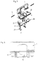
- FIG. 1 shows a diagram of a hinge
- FIG. 2 shows an exploded diagram of the hinge cup according to the hinge according to FIG. 1
- 3 shows a longitudinal section through a hinge cup in the tension-free state
- 4 shows a similar longitudinal section, the hinge cup being braced in the hole in the furniture part
- FIG. 5 shows a diagrammatic and exploded view of a further exemplary embodiment of the invention
- FIG. 6 shows a side view of the hinge cup according to FIG. 5, partly in section.
- FIG. 1 and 2 show a hinge with a hinge cup 4 which is connected to a hinge arm 20 via articulated lever 11.
- the hinge cup 4 can be inserted into a bore 16 in a door leaf 13. It has a flange 23 which is covered by a bracket 1.
- the bracket 1 comprises two eccentric levers 1 '.
- the tie rod-like expansion parts 2 are held on the bracket 1 by means of bolts 5.
- the hinge arm 20 is connected to a base plate 8 in a conventional manner.
- the base plate 8 has dowels that can be used in bores in a furniture side wall 12.
- the hinge cup 4 which is preferably made from a metal, for example die-cast, or from sheet metal, is provided on the side with clamping jaws 21 made of plastic or rubber.
- the clamping jaws 21 are visco-elastic or rubber-elastic and are pressed flat against the wall of the bore 16 when the hinge cup 4 is clamped.
- the expansion parts 2 are arranged between the clamping jaws 21 and the dowel pot 4.
- the expansion parts 2 are provided with projecting pointed hooks 3 at their free ends. Opposite the hooks 3, pressure cams 6 are formed on the expansion parts, which are supported on the hinge cup wall.
- bracket 1 If the bracket 1 is folded over, d. H. printed on the flange 23, the expansion parts 2 are tightened, i. H. out of the bore 16 and moved to the flange 23.
- the pressure cam 6 has an upper concave boundary surface 7 which, in the relaxed position (FIG. 3), bears against the arch 8 which forms the transition from the bottom 9 of the hinge cup 4 to the side wall 10 of the hinge cup 4.
- the pressing of the jaws 21 against the wall of the bore 16 is further strengthened in that the jaws 21 by tightening the expansion parts 2 in the Height pressed together and thus pressed outwards.
- the clamping jaws 21 provide a good hold in a chipboard material due to their flat pressure on the wall of the bore 16.
- the effect of the hook 3 can go unnoticed.
- the hinge cup 4 is inserted into a solid wood door leaf, its hold is effected in particular by the hooks 3 which cut into the wall of the bore 16.
- the hooks 3, as can be seen in FIG. 2, are designed in the same way as the clamping jaws 21.
- the clamping jaws 21 have lateral projections 14, in which grooves 15 are formed, in which edge webs 17 of the expansion parts 2 are guided.
- Centering pins 17 are advantageously formed on the flange 23 of the hinge cup 4, which prevent the hinge cup 4 from rotating.
- Suitable materials for the jaws 21 are, for example, polyurethane or rubber.
- the hooks 3 have a notch 24 on the inside, into which a nose 25 formed on the clamping jaws 21 projects.
- the hinge cup 4 which is preferably made from a metal, for example die-cast, or stamped from sheet metal, is surrounded by a holding part 26 made from plastic.
- the holding part 26 has the lateral clamping jaws 21, which laterally encompass the actual dowel cup 4, leaving the flange 23 free.
- the expansion parts 2 are arranged between the clamping jaws 21 and the dowel pot 4.
- the expansion parts 2 designed as tie rods are in turn connected to a bracket 1 by means of axes 5.
- the expansion parts 2 are provided at their free ends with arcuate expansion bodies 27 which have an approximately triangular cross section.
- bracket 1 If the bracket 1 is folded over, d. H. pressed onto the flange 23, the expansion parts 2 are tightened, i. H. out of the bore 16 and moved to the flange 23, their bow-shaped expansion bodies 27 pressing the clamping jaws 21 outwards against the wall of the bore 16.
- the bracket 1 which is mounted on a diameter line of the hinge cup 4, which is aligned parallel to the hinge axes, is designed as a handle for pulling the hinge cup 4 out of the bore 16 of the door leaf 13.
Abstract
Description
Die Erfindung bezieht sich auf einen Scharniertopf mit einem in eine Bohrung in einem Möbelteil einsetzbaren Gehäuse und mit in die Bohrung einsetzbaren dübelartigen spreizbaren Klemmbacken, die über als Zuganker ausgeführte Spreizteile an die Bohrungswandung preßbar sind, wobei die Spreizteile über einen Exzenterhebel in der Einsetzrichtung des Scharniertopfes senkrecht zu dessen Montageebene bewegbar sind und die Spreizung der Verankerungsteile dann erfolgt, wenn die Spreizteile in der Richtung vom Einsteckende des Scharniertopfes zu dessen Montagefläche bewegt werden.The invention relates to a hinge cup with a housing which can be inserted into a bore in a furniture part and with dowel-like expandable clamping jaws which can be inserted into the bore and which can be pressed against the bore wall by means of expansion parts designed as tie rods, the expansion parts via an eccentric lever in the direction of insertion of the hinge cup are movable perpendicular to the mounting plane and the expansion of the anchoring parts occurs when the expansion parts are moved in the direction from the insertion end of the hinge cup to its mounting surface.
Die Befestigung von Möbelbeschlägen mittels Dübeln oder dübelartiger Klemmteile hat gegenüber der Befestigung mittels Schrauben den Vorteil der besseren Haltbarkeit bzw. Verankerungskraft und ist nach dem derzeitigen Stand der Technik die übliche Art der Befestigung.The fastening of furniture fittings by means of dowels or dowel-like clamping parts has the advantage of better durability or anchoring force than fastening by means of screws and is the usual type of fastening according to the current state of the art.
Aufgabe der Erfindung ist es, einen Scharniertopf der eingangs erwähnten Art, der ohne Werkzeug montiert und ebenso wieder gelöst werden kann, dahingehend zu verbessern, daß er sowohl in einer Spanplatte als auch in Hartholz vorteilhaft montiert werden kann.The object of the invention is to improve a hinge cup of the type mentioned, which can be assembled without tools and can also be released again, in such a way that it can be advantageously mounted both in a chipboard and in hardwood.
Die erfindungsgemäße Aufgabe wird dadurch gelöst, daß die Verankerungsteile von am Mantel des Scharniertopfes angeordneten zylindersegmentförmigen Klemmbacken aus zähelastischem Material, beispielsweise Kunststoff oder Gummi, gebildet werden und daß die Zuganker zwischen dem Scharniertopf und den Klemmbacken angeordnet sind.The object of the invention is achieved in that the anchoring parts of cylindrical segment-shaped clamping jaws arranged on the jacket of the hinge cup are made of tough elastic material, for example plastic or rubber, and in that the tie rods are arranged between the hinge cup and the clamping jaws.
Nachfolgend werden Ausführungsbeispiele der Erfindung anhand der Figuren der beiliegenden Zeichnungen eingehend beschrieben.Exemplary embodiments of the invention are described in detail below with reference to the figures in the accompanying drawings.
Die Fig. 1 zeigt ein Schaubild eines Scharniers; die Fig. 2 zeigt ein auseinandergezogenes Schaubild des Scharniertopfes gemäß dem Scharnier nach der Fig. 1; die Fig. 3 zeigt einen Längsschnitt durch einen Scharniertopf im spannungsfreien Zustand; die Fig. 4 zeigt einen gleichen Längsschnitt, wobei der Scharniertopf in der Bohrung im Möbelteil verspannt ist; die Fig. 5 zeigt schaubildlich und auseinandergezogen ein weiteres Ausführungsbeispiel der Erfindung und die Fig. 6 zeigt eine Seitenansicht des Scharniertopfes nach Fig. 5 teilweise im Schnitt.Fig. 1 shows a diagram of a hinge; FIG. 2 shows an exploded diagram of the hinge cup according to the hinge according to FIG. 1; 3 shows a longitudinal section through a hinge cup in the tension-free state; 4 shows a similar longitudinal section, the hinge cup being braced in the hole in the furniture part; FIG. 5 shows a diagrammatic and exploded view of a further exemplary embodiment of the invention and FIG. 6 shows a side view of the hinge cup according to FIG. 5, partly in section.
Die Fig. 1 und 2 zeigen ein Scharnier mit einem Scharniertopf 4, der über Gelenkhebel 11 mit einem Scharnierarm 20 verbunden ist. Der Scharniertopf 4 ist in eine Bohrung 16 eines Türflügels 13 einsetzbar. Er weist einen Flansch 23 auf, der von einem Bügel 1 abgedeckt wird. Der Bügel 1 umfaßt zwei Exzenterhebel 1'. Die zugankerartigen Spreizteile 2 sind mittels Bolzen 5 am Bügel 1 gehalten.1 and 2 show a hinge with a
Der Scharnierarm 20 ist in herkömmlicher Weise mit einer Grundplatte 8 verbunden. Die Grundplatte 8 weist Dübel auf, die in Bohrungen in einer Möbelseitenwand 12 einsetzbar sind.The
Im gezeigten Ausführungsbeispiel ist der vorzugsweise aus einem Metall, beispielsweise Druckguß, oder aus Blech gefertigte Scharniertopf 4 seitlich mit Klemmbacken 21 aus Kunststoff oder Gummi versehen. Die Klemmbacken 21 sind viskoelastisch bzw. gummielastisch und werden beim Verspannen des Scharniertopfes 4 flächig an die Wandung der Bohrung 16 gepreßt.In the exemplary embodiment shown, the
Zwischen den Klemmbacken 21 und dem Dübeltopf 4 sind die Spreizteile 2 angeordnet.The
Im Ausführungsbeispiel nach den Fig. 2 bis 4 sind die Spreizteile 2 an ihren freien Enden mit abstehenden spitzen Haken 3 versehen. Den Haken 3 gegenüberliegend sind an den Spreizteilen 2 Anpreßnocken 6 ausgebildet, die sich an der Scharniertopfwandung abstützen.In the exemplary embodiment according to FIGS. 2 to 4, the
Wird der Bügel 1 umgeklappt, d. h. auf den Flansch 23 gedruckt, werden die Spreizteile 2 angezogen, d. h. aus der Bohrung 16 heraus und zum Flansch 23 bewegt.If the
Der Anpreßnocken 6 weist eine obere konkave Begrenzungsfläche 7 auf, die in der entspannten Stellung (Fig. 3) am Bogen 8 anliegt, der den Übergang vom Boden 9 des Scharniertopfes 4 zur Seitenwand 10 des Scharniertopfes 4 bildet.The
Wird der Bügel 1 umgeklappt und die Spreizteile 2, wie oben beschrieben, angezogen, fährt der Anpreßnocken 6 entlang des Bogens 8 nach oben (gemäß Zeichnung) und der Spreizteil 2 wird nach außen zur Wandung der Bohrung 16 gedrückt.If the
Dadurch werden einerseits die Klemmbacken 21 an die Wandung der Bohrung 16 gedrückt und andererseits werden die Haken 3 mit ihren Spitzen in die Wandung getrieben.As a result, on the one hand the
Das Anpressen der Klemmbacken 21 an die Wandung der Bohrung 16 wird noch dadurch gestärkt, daß die Klemmbacken 21 durch das Anziehen der Spreizteile 2 in der Höhe zusammengepreßt und somit nach außen gedrückt werden.The pressing of the
Die Klemmbacken 21 bewirken durch ihre flächige Anpressung an die Wandung der Bohrung 16 einen guten Halt in einem Spanplattenmaterial. Die Wirkung der Haken 3 kann dabei unbeachtet bleiben. Wird jedoch der Scharniertopf 4 in einen Türflügel aus Vollholz eingesetzt, wird sein Halt insbesondere durch die Haken 3 bewirkt, die sich in die Wandung der Bohrung 16 einschneiden.The
Die Haken 3 sind, wie aus der Fig. 2 ersichtlich, ebenso wie die Klemmbacken 21 segmentförmig ausgeführt. Die Klemmbacken 21 weisen seitliche Vorsprünge 14 auf, in denen Nuten 15 ausgebildet sind, in denen Randstege 17 der Spreizteile 2 geführt sind.The
Am Flansch 23 des Scharniertopfes 4 sind vorteilhaft Zentrierzapfen 17 ausgebildet, die ein Verdrehen des Scharniertopfes 4 verhindern.Centering
Geeignete Materialien für die Klemmbacken 21 sind beispielsweise Polyurethan oder Gummi.Suitable materials for the
Die Haken 3 weisen innen eine Einkerbung 24 auf, in die eine am Klemmbacken 21 ausgebildete Nase 25 ragt.The
In der Spannstellung wird der Flansch 23 vom Bügel 1 abgedeckt und der Topfbereich des Scharniertopfes 4 zur Gänze freigelassen.In the clamping position, the
Im Ausführungsbeispiel nach der Fig. 5 ist der vorzugsweise aus einem Metall, beispielsweise Druckguß, gefertigte oder aus Blech gestanzte Scharniertopf 4 von einem Halteteil 26 aus Kunststoff umgeben. Der Halteteil 26 weist die seitlichen Klemmbacken 21 auf, die den eigentlichen Dübeltopf 4 unter Freilassung des Flansches 23 seitlich umgreifen.In the exemplary embodiment according to FIG. 5, the
Zwischen den Klemmbacken 21 und dem Dübeltopf 4 sind die Spreizteile 2 angeordnet. Die als Zuganker ausgeführten Spreizteile 2 sind mittels Achsen 5 wiederum mit einem Bügel 1 verbunden.The
Die Spreizteile 2 sind an ihren freien Enden mit bogenförmigen Spreizkörper 27 versehen, die einen annähernd dreieckigen Querschnitt aufweisen.The
Wird der Bügel 1 umgeklappt, d. h. auf den Flansch 23 gedrückt, werden die Spreizteile 2 angezogen, d. h. aus der Bohrung 16 heraus und zum Flansch 23 bewegt, wobei ihre bügelförmigen Spreizkörper 27 die Klemmbacken 21 nach außen an die Wandung der Bohrung 16 drücken.If the
Der Bügel 1, der auf einer Durchmesserlinie des Scharniertopfes 4, die parallel zu den Scharnierachsen ausgerichtet ist, gelagert ist, ist als Griff zum Herausziehen des Scharniertopfes 4 aus der Bohrung 16 des Türflügels 13 ausgebildet.The
Claims (15)
Priority Applications (1)
| Application Number | Priority Date | Filing Date | Title |
|---|---|---|---|
| DE9421776U DE9421776U1 (en) | 1993-02-08 | 1994-01-31 | Hinge cup |
Applications Claiming Priority (4)
| Application Number | Priority Date | Filing Date | Title |
|---|---|---|---|
| AT21893A AT407415B (en) | 1993-02-08 | 1993-02-08 | Furniture fitting |
| AT218/93 | 1993-02-08 | ||
| AT1834/93 | 1993-09-10 | ||
| AT183493A AT401796B (en) | 1993-09-10 | 1993-09-10 | Hinge bowl |
Publications (2)
| Publication Number | Publication Date |
|---|---|
| EP0610765A1 true EP0610765A1 (en) | 1994-08-17 |
| EP0610765B1 EP0610765B1 (en) | 1996-04-17 |
Family
ID=25591912
Family Applications (1)
| Application Number | Title | Priority Date | Filing Date |
|---|---|---|---|
| EP94101368A Expired - Lifetime EP0610765B1 (en) | 1993-02-08 | 1994-01-31 | Hinge cup |
Country Status (8)
| Country | Link |
|---|---|
| US (2) | US5463796A (en) |
| EP (1) | EP0610765B1 (en) |
| JP (1) | JP2660656B2 (en) |
| AT (1) | ATE136977T1 (en) |
| CA (1) | CA2115085C (en) |
| DE (1) | DE59400198D1 (en) |
| ES (1) | ES2086240T3 (en) |
| HK (1) | HK22197A (en) |
Cited By (16)
| Publication number | Priority date | Publication date | Assignee | Title |
|---|---|---|---|---|
| DE4427293A1 (en) * | 1993-10-22 | 1995-04-27 | Grass Ag | Quick-mounting pot for furniture hinges |
| DE29506600U1 (en) * | 1995-04-19 | 1995-09-07 | Salice Arturo Spa | Fastener |
| AT968U1 (en) * | 1994-06-18 | 1996-08-26 | Grass Ag | HINGE POT |
| DE19516084A1 (en) * | 1995-05-03 | 1996-11-07 | Lautenschlaeger Mepla Werke | Edge contact device for door |
| DE19521909A1 (en) * | 1995-05-10 | 1996-11-14 | Lautenschlaeger Mepla Werke | Door attachment for furniture hinge |
| US5715577A (en) * | 1995-05-10 | 1998-02-10 | Mepla-Werke Lautenschlager Gmbh & Co. Kg | Door-related member of a furniture hinge |
| DE29717508U1 (en) * | 1997-09-30 | 1998-08-27 | Lautenschlaeger Mepla Werke | Furniture fitting part for tool-free installation in a recess in a furniture part, in particular door wing stop part for furniture hinges |
| WO1999024723A1 (en) * | 1997-11-07 | 1999-05-20 | Julius Blum Gesellschaft Mbh | Furniture fitting |
| AT406885B (en) * | 1993-10-22 | 2000-10-25 | Grass Gmbh | QUICK ASSEMBLY POT FOR FURNITURE HINGES |
| AT412187B (en) * | 1996-10-24 | 2004-11-25 | Hettich Paul Gmbh & Co | FURNITURE FITTING FOR CONNECTING TWO FURNITURE PARTS |
| WO2006053354A1 (en) * | 2004-11-17 | 2006-05-26 | Julius Blum Gmbh | Hinge, particularly for movable furniture parts, with an integrated damping device |
| EP2090731A2 (en) | 2008-02-13 | 2009-08-19 | Agostino Ferrari S.p.A. | Rapidly mounted hinge wing for furniture |
| DE202008007345U1 (en) | 2008-05-31 | 2009-10-08 | Grass Gmbh & Co. Kg | Hinge cup for furniture hinges |
| US7669285B2 (en) | 2004-03-12 | 2010-03-02 | Mepla-Werke Mautenschlaeger Gmbh & Co. Kg | Damping device for furniture hinges |
| DE102014113713A1 (en) | 2014-09-23 | 2016-03-24 | Samet Kalip Ve Maden Esya San. Ve Tic. A.S. | hinge |
| AT522457A4 (en) * | 2019-05-17 | 2020-11-15 | Blum Gmbh Julius | Furniture fittings |
Families Citing this family (13)
| Publication number | Priority date | Publication date | Assignee | Title |
|---|---|---|---|---|
| DE19514388C2 (en) * | 1995-04-19 | 2002-04-18 | Scharwaechter Gmbh Co Kg | Door or flap hinge for motor vehicles |
| DE19517924B4 (en) * | 1995-05-16 | 2006-03-02 | MEPLA-WERKE LAUTENSCHLäGER GMBH & CO. KG | Furniture fitting |
| AT404666B (en) * | 1995-10-30 | 1999-01-25 | Blum Gmbh Julius | DRAWER |
| DE29703227U1 (en) * | 1997-02-24 | 1998-07-02 | Praemeta | Quick mounting pot for furniture hinges |
| IT244455Y1 (en) * | 1998-12-23 | 2002-03-11 | Ferrari Franco | MOUNTING DEVICES WITH EXPANSION DOWEL IN PARTICULAR FOR HINGES FOR FURNITURE |
| IT244454Y1 (en) | 1998-12-23 | 2002-03-11 | Ferrari Franco | BASE FOR QUICK FASTENING OF A HINGE FOR FURNITURE |
| AT502613B1 (en) * | 2003-04-15 | 2007-08-15 | Blum Gmbh Julius | DAMPER WITH HOUSING |
| US20050196249A1 (en) * | 2004-03-03 | 2005-09-08 | Ting-Tsai Huang | Hinge fastening apparatus |
| US8136781B2 (en) * | 2006-08-17 | 2012-03-20 | Rockler Companies, Inc. | Workpiece support apparatus and method |
| AT508385B1 (en) * | 2009-10-12 | 2011-01-15 | Blum Gmbh Julius | FASTENING DEVICE FOR FURNITURE FITTINGS |
| AT508384B1 (en) * | 2009-10-12 | 2011-01-15 | Blum Gmbh Julius | FASTENING DEVICE FOR FURNITURE FITTINGS |
| DE102014113714A1 (en) * | 2014-09-23 | 2016-03-24 | Samet Kalip Ve Maden Esya San. Ve Tic. A.S. | hinge |
| US9664215B2 (en) * | 2014-11-20 | 2017-05-30 | Hardware Resources, Inc. | Removable compact hinge and method of use |
Citations (2)
| Publication number | Priority date | Publication date | Assignee | Title |
|---|---|---|---|---|
| GB1542487A (en) * | 1975-09-29 | 1979-03-21 | Blum Gmbh Julius | Dowels |
| GB2027482A (en) * | 1978-07-28 | 1980-02-20 | Heinze Richard Gmbh Co Kg | Furniture fittings |
Family Cites Families (4)
| Publication number | Priority date | Publication date | Assignee | Title |
|---|---|---|---|---|
| FR1550119A (en) * | 1967-07-06 | 1968-12-20 | ||
| DE1904781A1 (en) * | 1969-01-31 | 1970-08-27 | Lautenschlaeger Kg Karl | Furniture hinge |
| DE2524503A1 (en) * | 1975-05-03 | 1976-12-30 | Hettich Paul & Co | Plastics wedge for holding hinge in furniture - comprises ridged and smooth wedge driven between hinge base and seat |
| DE2837327C2 (en) * | 1978-08-26 | 1984-03-01 | Richard Heinze Gmbh & Co Kg, 4900 Herford | Mounting plate for attaching a hinge arm to a piece of furniture |
-
1994
- 1994-01-31 DE DE59400198T patent/DE59400198D1/en not_active Expired - Lifetime
- 1994-01-31 ES ES94101368T patent/ES2086240T3/en not_active Expired - Lifetime
- 1994-01-31 AT AT94101368T patent/ATE136977T1/en active
- 1994-01-31 EP EP94101368A patent/EP0610765B1/en not_active Expired - Lifetime
- 1994-02-07 CA CA002115085A patent/CA2115085C/en not_active Expired - Fee Related
- 1994-02-07 US US08/192,828 patent/US5463796A/en not_active Ceased
- 1994-02-07 JP JP6033212A patent/JP2660656B2/en not_active Expired - Lifetime
-
1997
- 1997-02-27 HK HK22197A patent/HK22197A/en not_active IP Right Cessation
- 1997-11-04 US US08/964,205 patent/USRE37236E1/en not_active Expired - Lifetime
Patent Citations (2)
| Publication number | Priority date | Publication date | Assignee | Title |
|---|---|---|---|---|
| GB1542487A (en) * | 1975-09-29 | 1979-03-21 | Blum Gmbh Julius | Dowels |
| GB2027482A (en) * | 1978-07-28 | 1980-02-20 | Heinze Richard Gmbh Co Kg | Furniture fittings |
Cited By (34)
| Publication number | Priority date | Publication date | Assignee | Title |
|---|---|---|---|---|
| DE4427293A1 (en) * | 1993-10-22 | 1995-04-27 | Grass Ag | Quick-mounting pot for furniture hinges |
| AT406885B (en) * | 1993-10-22 | 2000-10-25 | Grass Gmbh | QUICK ASSEMBLY POT FOR FURNITURE HINGES |
| AT968U1 (en) * | 1994-06-18 | 1996-08-26 | Grass Ag | HINGE POT |
| DE29506600U1 (en) * | 1995-04-19 | 1995-09-07 | Salice Arturo Spa | Fastener |
| DE19516084C2 (en) * | 1995-05-03 | 1999-09-16 | Lautenschlaeger Mepla Werke | Door wing stop for furniture hinges |
| DE19516084A1 (en) * | 1995-05-03 | 1996-11-07 | Lautenschlaeger Mepla Werke | Edge contact device for door |
| US5632067A (en) * | 1995-05-03 | 1997-05-27 | Mepla-Werke Lautenschlager Gmbh & Co. Kg | Door-related hinge member for hanging a cabinet door |
| ES2147056A1 (en) * | 1995-05-03 | 2000-08-16 | Lautenschlaeger Mepla Werke | Door-related hinge member for hanging a cabinet door |
| AT404377B (en) * | 1995-05-03 | 1998-11-25 | Lautenschlaeger Mepla Werke | DOOR WING HINGE FOR FURNITURE HINGES |
| DE19521909C2 (en) * | 1995-05-10 | 2003-12-24 | Lautenschlaeger Mepla Werke | Door wing stop for furniture hinges |
| DE19521909A1 (en) * | 1995-05-10 | 1996-11-14 | Lautenschlaeger Mepla Werke | Door attachment for furniture hinge |
| AT409650B (en) * | 1995-05-10 | 2002-09-25 | Lautenschlaeger Mepla Werke | DOOR WING HINGE FOR FURNITURE HINGES |
| US5715577A (en) * | 1995-05-10 | 1998-02-10 | Mepla-Werke Lautenschlager Gmbh & Co. Kg | Door-related member of a furniture hinge |
| AT412187B (en) * | 1996-10-24 | 2004-11-25 | Hettich Paul Gmbh & Co | FURNITURE FITTING FOR CONNECTING TWO FURNITURE PARTS |
| DE29717508U1 (en) * | 1997-09-30 | 1998-08-27 | Lautenschlaeger Mepla Werke | Furniture fitting part for tool-free installation in a recess in a furniture part, in particular door wing stop part for furniture hinges |
| US6073311A (en) * | 1997-09-30 | 2000-06-13 | Mepla-Werke Lautenschlager Gmbh & Co. Kg | Metal fitting for furniture, which can be mounted without tools in a recess in a furniture part, especially a stop part for a door leaf for furniture hinges |
| US6416244B1 (en) * | 1997-11-07 | 2002-07-09 | Julius Blum Gesellschaft M.B.H. | Furniture fitting |
| WO1999024723A1 (en) * | 1997-11-07 | 1999-05-20 | Julius Blum Gesellschaft Mbh | Furniture fitting |
| US7669285B2 (en) | 2004-03-12 | 2010-03-02 | Mepla-Werke Mautenschlaeger Gmbh & Co. Kg | Damping device for furniture hinges |
| WO2006053354A1 (en) * | 2004-11-17 | 2006-05-26 | Julius Blum Gmbh | Hinge, particularly for movable furniture parts, with an integrated damping device |
| AT501397A1 (en) * | 2004-11-17 | 2006-08-15 | Blum Gmbh Julius | HINGE, ESPECIALLY FOR MOVABLE FURNITURE PARTS, WITH AN INTEGRATED DAMPER |
| AT501397B1 (en) * | 2004-11-17 | 2007-08-15 | Blum Gmbh Julius | HINGE, ESPECIALLY FOR MOVABLE FURNITURE PARTS, WITH AN INTEGRATED DAMPER |
| EP2090731A3 (en) * | 2008-02-13 | 2013-01-30 | Agostino Ferrari S.p.A. | Rapidly mounted hinge wing for furniture |
| EP2090731A2 (en) | 2008-02-13 | 2009-08-19 | Agostino Ferrari S.p.A. | Rapidly mounted hinge wing for furniture |
| US8006348B2 (en) | 2008-02-13 | 2011-08-30 | Agostino Ferrari S.P.A | Rapidly mounted hinge wing for furniture |
| DE202008007345U1 (en) | 2008-05-31 | 2009-10-08 | Grass Gmbh & Co. Kg | Hinge cup for furniture hinges |
| DE102014113713A1 (en) | 2014-09-23 | 2016-03-24 | Samet Kalip Ve Maden Esya San. Ve Tic. A.S. | hinge |
| WO2016045939A1 (en) * | 2014-09-23 | 2016-03-31 | Samet Kalip Ve Maden Esya San. Ve Tic. A.S. | Furniture hinge |
| DE102014113713B4 (en) * | 2014-09-23 | 2017-02-23 | Samet Kalip Ve Maden Esya San. Ve Tic. A.S. | hinge |
| CN106795728A (en) * | 2014-09-23 | 2017-05-31 | 土耳其萨麦提模子及矿物工商股份公司 | Hinge for furniture |
| CN106795728B (en) * | 2014-09-23 | 2018-08-03 | 土耳其萨麦提模子及矿物工商股份公司 | Hinge for furniture |
| US10260263B2 (en) | 2014-09-23 | 2019-04-16 | Samet Kalip Ve Maden Esya San. Ve Tic. A.S. | Furniture hinge |
| AT522457A4 (en) * | 2019-05-17 | 2020-11-15 | Blum Gmbh Julius | Furniture fittings |
| AT522457B1 (en) * | 2019-05-17 | 2020-11-15 | Blum Gmbh Julius | Furniture fittings |
Also Published As
| Publication number | Publication date |
|---|---|
| DE59400198D1 (en) | 1996-05-23 |
| CA2115085C (en) | 1999-07-20 |
| HK22197A (en) | 1997-02-27 |
| EP0610765B1 (en) | 1996-04-17 |
| USRE37236E1 (en) | 2001-06-26 |
| ATE136977T1 (en) | 1996-05-15 |
| US5463796A (en) | 1995-11-07 |
| CA2115085A1 (en) | 1994-08-09 |
| JPH06240941A (en) | 1994-08-30 |
| JP2660656B2 (en) | 1997-10-08 |
| ES2086240T3 (en) | 1996-06-16 |
Similar Documents
| Publication | Publication Date | Title |
|---|---|---|
| EP0610765B1 (en) | Hinge cup | |
| DE2723850C2 (en) | Furniture hinge | |
| DE3304569C1 (en) | Device for adjusting a first component relative to a second component | |
| EP0698357B1 (en) | Fitting for furniture, especially connector | |
| DE4219681C2 (en) | Adjustable lifting hinge | |
| DE3445885C2 (en) | ||
| WO1989002022A1 (en) | Hinge | |
| DE3535963C2 (en) | ||
| DE2721625C2 (en) | ||
| DE2748623C2 (en) | Hardware for a frameless all-glass door | |
| DE2624843C3 (en) | Lockable inclination device for seating furniture, e.g. for an office chair | |
| DE2642488B2 (en) | Fitting for the detachable connection of parts of a piece of furniture | |
| WO1990008905A1 (en) | Safety device for a screw | |
| EP1167670A2 (en) | Mounting plate for fixing a hinge arm of a cabinet | |
| DE1602843C3 (en) | Cutting tool for machining | |
| CH678447A5 (en) | Fitment for holding end of frame slats | |
| DE2727962C3 (en) | Furniture fitting part | |
| DE8237162U1 (en) | hinge | |
| EP0791714A1 (en) | Hinge | |
| DE8015887U1 (en) | MULTI-PIECE BASE PLATE FOR FURNITURE HINGES | |
| DE2815816A1 (en) | Adjustable hinge arm on support plate - has screw end plug with preloaded locking washers preventing play | |
| AT401796B (en) | Hinge bowl | |
| AT407415B (en) | Furniture fitting | |
| AT357290B (en) | FITTING FOR RELEASABLE CONNECTION OF PARTS OF A FURNITURE OR DGL. | |
| EP0484685A1 (en) | Actuator |
Legal Events
| Date | Code | Title | Description |
|---|---|---|---|
| PUAI | Public reference made under article 153(3) epc to a published international application that has entered the european phase |
Free format text: ORIGINAL CODE: 0009012 |
|
| AK | Designated contracting states |
Kind code of ref document: A1 Designated state(s): AT CH DE ES FR GB IT LI SE |
|
| 17P | Request for examination filed |
Effective date: 19941013 |
|
| 17Q | First examination report despatched |
Effective date: 19951005 |
|
| GRAH | Despatch of communication of intention to grant a patent |
Free format text: ORIGINAL CODE: EPIDOS IGRA |
|
| GRAA | (expected) grant |
Free format text: ORIGINAL CODE: 0009210 |
|
| AK | Designated contracting states |
Kind code of ref document: B1 Designated state(s): AT CH DE ES FR GB IT LI SE |
|
| REF | Corresponds to: |
Ref document number: 136977 Country of ref document: AT Date of ref document: 19960515 Kind code of ref document: T |
|
| ITF | It: translation for a ep patent filed |
Owner name: BUGNION S.P.A. |
|
| REG | Reference to a national code |
Ref country code: CH Ref legal event code: NV Representative=s name: R. A. EGLI & CO. PATENTANWAELTE |
|
| REF | Corresponds to: |
Ref document number: 59400198 Country of ref document: DE Date of ref document: 19960523 |
|
| REG | Reference to a national code |
Ref country code: ES Ref legal event code: FG2A Ref document number: 2086240 Country of ref document: ES Kind code of ref document: T3 |
|
| GBT | Gb: translation of ep patent filed (gb section 77(6)(a)/1977) |
Effective date: 19960520 |
|
| ET | Fr: translation filed | ||
| PLBE | No opposition filed within time limit |
Free format text: ORIGINAL CODE: 0009261 |
|
| STAA | Information on the status of an ep patent application or granted ep patent |
Free format text: STATUS: NO OPPOSITION FILED WITHIN TIME LIMIT |
|
| 26N | No opposition filed | ||
| PGFP | Annual fee paid to national office [announced via postgrant information from national office to epo] |
Ref country code: SE Payment date: 20010117 Year of fee payment: 8 |
|
| PGFP | Annual fee paid to national office [announced via postgrant information from national office to epo] |
Ref country code: CH Payment date: 20010124 Year of fee payment: 8 |
|
| PGFP | Annual fee paid to national office [announced via postgrant information from national office to epo] |
Ref country code: GB Payment date: 20010131 Year of fee payment: 8 Ref country code: FR Payment date: 20010131 Year of fee payment: 8 |
|
| REG | Reference to a national code |
Ref country code: GB Ref legal event code: IF02 |
|
| PG25 | Lapsed in a contracting state [announced via postgrant information from national office to epo] |
Ref country code: LI Free format text: LAPSE BECAUSE OF NON-PAYMENT OF DUE FEES Effective date: 20020131 Ref country code: GB Free format text: LAPSE BECAUSE OF NON-PAYMENT OF DUE FEES Effective date: 20020131 Ref country code: CH Free format text: LAPSE BECAUSE OF NON-PAYMENT OF DUE FEES Effective date: 20020131 |
|
| PG25 | Lapsed in a contracting state [announced via postgrant information from national office to epo] |
Ref country code: SE Free format text: LAPSE BECAUSE OF NON-PAYMENT OF DUE FEES Effective date: 20020201 |
|
| REG | Reference to a national code |
Ref country code: CH Ref legal event code: PL |
|
| GBPC | Gb: european patent ceased through non-payment of renewal fee |
Effective date: 20020131 |
|
| EUG | Se: european patent has lapsed |
Ref document number: 94101368.2 |
|
| PG25 | Lapsed in a contracting state [announced via postgrant information from national office to epo] |
Ref country code: FR Free format text: LAPSE BECAUSE OF NON-PAYMENT OF DUE FEES Effective date: 20020930 |
|
| REG | Reference to a national code |
Ref country code: FR Ref legal event code: ST |
|
| PGFP | Annual fee paid to national office [announced via postgrant information from national office to epo] |
Ref country code: IT Payment date: 20120128 Year of fee payment: 19 |
|
| PGFP | Annual fee paid to national office [announced via postgrant information from national office to epo] |
Ref country code: ES Payment date: 20130114 Year of fee payment: 20 |
|
| PGFP | Annual fee paid to national office [announced via postgrant information from national office to epo] |
Ref country code: AT Payment date: 20130129 Year of fee payment: 20 |
|
| PGFP | Annual fee paid to national office [announced via postgrant information from national office to epo] |
Ref country code: DE Payment date: 20130327 Year of fee payment: 20 |
|
| REG | Reference to a national code |
Ref country code: DE Ref legal event code: R071 Ref document number: 59400198 Country of ref document: DE |
|
| REG | Reference to a national code |
Ref country code: DE Ref legal event code: R071 Ref document number: 59400198 Country of ref document: DE |
|
| REG | Reference to a national code |
Ref country code: AT Ref legal event code: MK07 Ref document number: 136977 Country of ref document: AT Kind code of ref document: T Effective date: 20140131 |
|
| PG25 | Lapsed in a contracting state [announced via postgrant information from national office to epo] |
Ref country code: DE Free format text: LAPSE BECAUSE OF EXPIRATION OF PROTECTION Effective date: 20140201 |
|
| REG | Reference to a national code |
Ref country code: ES Ref legal event code: FD2A Effective date: 20140925 |
|
| PG25 | Lapsed in a contracting state [announced via postgrant information from national office to epo] |
Ref country code: ES Free format text: LAPSE BECAUSE OF EXPIRATION OF PROTECTION Effective date: 20140201 |