EP0600610A2 - A position determining system and method - Google Patents
A position determining system and method Download PDFInfo
- Publication number
- EP0600610A2 EP0600610A2 EP93308694A EP93308694A EP0600610A2 EP 0600610 A2 EP0600610 A2 EP 0600610A2 EP 93308694 A EP93308694 A EP 93308694A EP 93308694 A EP93308694 A EP 93308694A EP 0600610 A2 EP0600610 A2 EP 0600610A2
- Authority
- EP
- European Patent Office
- Prior art keywords
- wand
- subject
- emitters
- receivers
- image data
- Prior art date
- Legal status (The legal status is an assumption and is not a legal conclusion. Google has not performed a legal analysis and makes no representation as to the accuracy of the status listed.)
- Granted
Links
Images


Classifications
-
- A—HUMAN NECESSITIES
- A61—MEDICAL OR VETERINARY SCIENCE; HYGIENE
- A61B—DIAGNOSIS; SURGERY; IDENTIFICATION
- A61B17/00—Surgical instruments, devices or methods, e.g. tourniquets
- A61B17/34—Trocars; Puncturing needles
- A61B17/3403—Needle locating or guiding means
-
- A—HUMAN NECESSITIES
- A61—MEDICAL OR VETERINARY SCIENCE; HYGIENE
- A61B—DIAGNOSIS; SURGERY; IDENTIFICATION
- A61B34/00—Computer-aided surgery; Manipulators or robots specially adapted for use in surgery
- A61B34/20—Surgical navigation systems; Devices for tracking or guiding surgical instruments, e.g. for frameless stereotaxis
-
- A—HUMAN NECESSITIES
- A61—MEDICAL OR VETERINARY SCIENCE; HYGIENE
- A61B—DIAGNOSIS; SURGERY; IDENTIFICATION
- A61B90/00—Instruments, implements or accessories specially adapted for surgery or diagnosis and not covered by any of the groups A61B1/00 - A61B50/00, e.g. for luxation treatment or for protecting wound edges
- A61B90/10—Instruments, implements or accessories specially adapted for surgery or diagnosis and not covered by any of the groups A61B1/00 - A61B50/00, e.g. for luxation treatment or for protecting wound edges for stereotaxic surgery, e.g. frame-based stereotaxis
-
- A—HUMAN NECESSITIES
- A61—MEDICAL OR VETERINARY SCIENCE; HYGIENE
- A61B—DIAGNOSIS; SURGERY; IDENTIFICATION
- A61B10/00—Other methods or instruments for diagnosis, e.g. instruments for taking a cell sample, for biopsy, for vaccination diagnosis; Sex determination; Ovulation-period determination; Throat striking implements
- A61B10/02—Instruments for taking cell samples or for biopsy
-
- A—HUMAN NECESSITIES
- A61—MEDICAL OR VETERINARY SCIENCE; HYGIENE
- A61B—DIAGNOSIS; SURGERY; IDENTIFICATION
- A61B17/00—Surgical instruments, devices or methods, e.g. tourniquets
- A61B17/00234—Surgical instruments, devices or methods, e.g. tourniquets for minimally invasive surgery
-
- A—HUMAN NECESSITIES
- A61—MEDICAL OR VETERINARY SCIENCE; HYGIENE
- A61B—DIAGNOSIS; SURGERY; IDENTIFICATION
- A61B17/00—Surgical instruments, devices or methods, e.g. tourniquets
- A61B2017/0046—Surgical instruments, devices or methods, e.g. tourniquets with a releasable handle; with handle and operating part separable
- A61B2017/00473—Distal part, e.g. tip or head
-
- A—HUMAN NECESSITIES
- A61—MEDICAL OR VETERINARY SCIENCE; HYGIENE
- A61B—DIAGNOSIS; SURGERY; IDENTIFICATION
- A61B17/00—Surgical instruments, devices or methods, e.g. tourniquets
- A61B2017/00477—Coupling
-
- A—HUMAN NECESSITIES
- A61—MEDICAL OR VETERINARY SCIENCE; HYGIENE
- A61B—DIAGNOSIS; SURGERY; IDENTIFICATION
- A61B34/00—Computer-aided surgery; Manipulators or robots specially adapted for use in surgery
- A61B34/10—Computer-aided planning, simulation or modelling of surgical operations
- A61B2034/107—Visualisation of planned trajectories or target regions
-
- A—HUMAN NECESSITIES
- A61—MEDICAL OR VETERINARY SCIENCE; HYGIENE
- A61B—DIAGNOSIS; SURGERY; IDENTIFICATION
- A61B34/00—Computer-aided surgery; Manipulators or robots specially adapted for use in surgery
- A61B34/20—Surgical navigation systems; Devices for tracking or guiding surgical instruments, e.g. for frameless stereotaxis
- A61B2034/2046—Tracking techniques
- A61B2034/2051—Electromagnetic tracking systems
-
- A—HUMAN NECESSITIES
- A61—MEDICAL OR VETERINARY SCIENCE; HYGIENE
- A61B—DIAGNOSIS; SURGERY; IDENTIFICATION
- A61B34/00—Computer-aided surgery; Manipulators or robots specially adapted for use in surgery
- A61B34/20—Surgical navigation systems; Devices for tracking or guiding surgical instruments, e.g. for frameless stereotaxis
- A61B2034/2046—Tracking techniques
- A61B2034/2055—Optical tracking systems
-
- A—HUMAN NECESSITIES
- A61—MEDICAL OR VETERINARY SCIENCE; HYGIENE
- A61B—DIAGNOSIS; SURGERY; IDENTIFICATION
- A61B34/00—Computer-aided surgery; Manipulators or robots specially adapted for use in surgery
- A61B34/20—Surgical navigation systems; Devices for tracking or guiding surgical instruments, e.g. for frameless stereotaxis
- A61B2034/2068—Surgical navigation systems; Devices for tracking or guiding surgical instruments, e.g. for frameless stereotaxis using pointers, e.g. pointers having reference marks for determining coordinates of body points
-
- A—HUMAN NECESSITIES
- A61—MEDICAL OR VETERINARY SCIENCE; HYGIENE
- A61B—DIAGNOSIS; SURGERY; IDENTIFICATION
- A61B90/00—Instruments, implements or accessories specially adapted for surgery or diagnosis and not covered by any of the groups A61B1/00 - A61B50/00, e.g. for luxation treatment or for protecting wound edges
- A61B90/36—Image-producing devices or illumination devices not otherwise provided for
- A61B2090/363—Use of fiducial points
-
- A—HUMAN NECESSITIES
- A61—MEDICAL OR VETERINARY SCIENCE; HYGIENE
- A61B—DIAGNOSIS; SURGERY; IDENTIFICATION
- A61B90/00—Instruments, implements or accessories specially adapted for surgery or diagnosis and not covered by any of the groups A61B1/00 - A61B50/00, e.g. for luxation treatment or for protecting wound edges
- A61B90/39—Markers, e.g. radio-opaque or breast lesions markers
- A61B2090/3954—Markers, e.g. radio-opaque or breast lesions markers magnetic, e.g. NMR or MRI
-
- A—HUMAN NECESSITIES
- A61—MEDICAL OR VETERINARY SCIENCE; HYGIENE
- A61B—DIAGNOSIS; SURGERY; IDENTIFICATION
- A61B90/00—Instruments, implements or accessories specially adapted for surgery or diagnosis and not covered by any of the groups A61B1/00 - A61B50/00, e.g. for luxation treatment or for protecting wound edges
- A61B90/39—Markers, e.g. radio-opaque or breast lesions markers
- A61B2090/3983—Reference marker arrangements for use with image guided surgery
-
- A—HUMAN NECESSITIES
- A61—MEDICAL OR VETERINARY SCIENCE; HYGIENE
- A61B—DIAGNOSIS; SURGERY; IDENTIFICATION
- A61B34/00—Computer-aided surgery; Manipulators or robots specially adapted for use in surgery
- A61B34/10—Computer-aided planning, simulation or modelling of surgical operations
-
- A—HUMAN NECESSITIES
- A61—MEDICAL OR VETERINARY SCIENCE; HYGIENE
- A61B—DIAGNOSIS; SURGERY; IDENTIFICATION
- A61B90/00—Instruments, implements or accessories specially adapted for surgery or diagnosis and not covered by any of the groups A61B1/00 - A61B50/00, e.g. for luxation treatment or for protecting wound edges
- A61B90/06—Measuring instruments not otherwise provided for
-
- A—HUMAN NECESSITIES
- A61—MEDICAL OR VETERINARY SCIENCE; HYGIENE
- A61B—DIAGNOSIS; SURGERY; IDENTIFICATION
- A61B90/00—Instruments, implements or accessories specially adapted for surgery or diagnosis and not covered by any of the groups A61B1/00 - A61B50/00, e.g. for luxation treatment or for protecting wound edges
- A61B90/39—Markers, e.g. radio-opaque or breast lesions markers
Definitions
- This invention relates to a position determining system and method. It finds particular application in conjunction with neurosurgery and will be described with particular reference thereto. However, it is to be appreciated, that the invention will also find application in conjunction with other medical procedures, industrial quality control procedures, and the like.
- Three-dimensional diagnostic image data of the brain and other body portions are commonly available with CT scanners, magnetic resonance images, and other medical diagnostic equipment. These imaging modalities provide structural detail with a resolution of a millimetre or better.
- a three-dimensional "localizer” is attached to the patient's skull.
- the localizer is a mechanical device with precisely known geometry and dimensions for guiding or positioning surgical instruments.
- the localizer is commonly attached to a ring or frame of metal or plastic from which the name "framed" stereotaxy has evolved. This frame is typically affixed to the patient using various mounting hardware methods that include sharp points or pins that pierce the skin and locate into the skull.
- the localizer is then mounted onto a frame.
- the localizer and frame provide the surgeon with the ability to position surgical instruments mechanically with a mechanical accuracy of a millimetre or better. However, anatomically, accuracy is somewhat less due to inaccuracies in the diagnostic imaging and patient motion.
- One of the difficulties that has arisen is accurately coordinating the coordinate system of the patient's skull or stereotaxy localizer with the coordinate system of the diagnostic data.
- One solution has been to image the patient with the stereotaxic frame attached. Because the stereotaxic frame appears in the resultant images, the surgeon is provided with a frame of reference in the images. Although relatively accurate in coordinating the two frames of reference, the use of the frame has numerous drawbacks including the need to mount the frame to the patient's head for both the imaging and the surgical procedures and the associated cost.
- a position determining system comprising: a subject support; a means for securing a preselected portion of a subject to the subject support; a frame assembly which mounts at least three receivers in a fixed relationship to the subject support closely adjacent the means for securing a portion of the subject to the subject support; at least one reference emitter mounted a fixed, known distance from the receivers, the reference emitter emitting a reference signal which travels from the reference emitter the fixed distance to the receivers; a calibration means for measuring a reference travel time of the reference signal over the fixed distance; a wand having a pointer and at least two emitters mounted thereto, the two wand emitters selectively emitting wand signals which are received by the at least three receivers; a wand position determining means for determining a position of the wand pointer by measuring wand signal travel times of the wand signals between the two wand emitters and the at least three receivers, the wand
- a position determining method comprising: a) securing a portion of a subject to a subject supporting surface in close proximity to at least three signal receivers that are mounted in a fixed relationship to the subject supporting surface; b) positioning a wand to designate selected locations on the subject portion, the wand having at least two wand emitters mounted thereon for selectively emitting signals which are received by the receivers; c) actuating the wand emitters to emit wand signals; d) from the wand emitter signals, calculating coordinates of the wand emitters in a coordinate system of the subject support; e) comparing a calculated distance between calculated wand emitter coordinates and a physical distance between the wand emitters; f) in response to the difference between the calculated distance and the physical distance exceeding a preselected standard, providing an unacceptable measurement signal.
- a position determining method comprising: a) securing a portion of a subject to a subject supporting surface in close proximity to at least three signal receivers that are mounted in a fixed relationship to the subject supporting surface, a reference signal emitter being fixedly mounted at a fixed, known distance from the plurality of receivers; b) positioning a wand to designate selected locations on the subject portion, the wand having at least two wand emitters mounted thereon for selectively emitting signals which are received by the receivers; c) actuating the wand emitters individually and the reference emitter in close temporal proximity to emit wand and reference signals; d) measuring travel durations for the wand and reference signals to travel from each of the wand emitters to the receivers and from the reference emitter to the receivers; e) from the travel times, calculating coordinates of the locations designated by the wand in a coordinate system of the subject support.
- One advantage of an apparatus and method embodying the present invention is that it provides a technique which simply and painlessly coordinates the coordinate system of three-dimensional image data obtained from one or more imaging modalities with the coordinate system of the patient prior to or during surgery.
- Another advantage of an apparatus and method embodying the present invention is that no frame is needed during the image acquisition scan.
- Another advantage of an apparatus and method embodying the present invention is that sterilization of necessary parts of the system is facilitated.
- Another advantage of an apparatus and method embodying the present invention is that it is easy to use and very user friendly.
- a subject such as a human patient
- a frame 12 is fixed to the patient support such that it is precisely positioned within the subject or subject support coordinate system. Mounting the frame 12 to the patient support permits the patient support to be turned, raised, lowered, wheeled to another location, or the like, without altering the patient coordinate system.
- the frame 12 supports a plurality of emitter/receiver combinations 14 mounted at fixed, known locations thereon.
- a head clamp 16 or other means securely positions the patient's head or other portion of the subject under consideration in the subject support coordinate system.
- the frame is mounted at a fixed or selectable angle from vertical such that the frame is positionable more toward the patient, yet still focusing on the region of interest of the patient.
- an operator console 18 houses a computer system 20 .
- the computer system can be remotely located and connected with the control console 18 by cabling.
- the computer system includes a three-dimensional data memory 22 .
- the stored three-dimensional image data preferably contains a video pixel value for each voxel or point in a three-dimensional rectangular grid of points, preferably a 256 x 256 x 256 grid.
- each image value represents one millimeter cube
- the image data represents about a 25.6 centimeter cube through the patient with one millimeter resolution.
- a plane selecting means 24 selects various two-dimensional planes of pixel values from the three-dimensional memory for display.
- the plane selecting means selects at least three planes: axial, sagittal, coronal, and oblique planes through a selectable point of the patient.
- the pixel values which lie on the selected axial, sagittal, coronal, and oblique planes are copied into corresponding image memories 26a , 26b , 26c , and 26d .
- a video processor means 28 converts the two-dimensional digital image representations from one or more of image memories 26 into appropriate signals for display on video monitors 30 or other appropriate display means.
- the surgeon positions a tip 40 of a wand 42 at the desired location.
- the locator system locates the coordinate of the tip and the trajectory of the wand.
- the wand includes a pair of emitters 44 and 46 which selectively emit positioning signals, ultrasonic signals in the preferred embodiment.
- the first emitter 44 has a fixed, known distance l1 from the tip 40 and the second emitter has a fixed, known distance l 2 from the first emitter 44 .
- the wand is readily sterilized by conventional techniques.
- the two emitters and the tip are preferably in linear alignment.
- the wand 42 may have a jog 48 which enables the tip and the two emitters to be disposed along a central axis or pointing direction of the wand.
- the frame 12 includes not only the plurality of receivers, e.g. microphones 50 in the preferred ultrasonic embodiment, but also a plurality of reference emitters 52 .
- the reference receivers are each spaced along side edges of the frame from adjacent receivers or microphones 50 by distances S1 and S2 .
- Each reference receiver is also spaced by a distance D across the frame from an oppositely disposed emitter 52 .
- the emitters and the microphones are normally not coplanar with the frame 12 .
- both distances or range values D are equal in length.
- the distance from the wand emitters to the frame, hence the position of the wand relative to the patient, is determined by the travel time of the sound.
- the velocity of the sound pulse through air is dependent upon both the temperature, the humidity, and the chemical composition of the air. These factors can and do vary significantly during an operation and from procedure to procedure.
- a calculation is performed to determine the speed of sound in the operating room.
- a calibrating means 60 selectively pulses the reference emitters 52 , receives the signals at receivers 50 , and processes the elapsed time information in accordance with the procedure of FIGURE 4.
- the calibration means 60 includes a step or means 62 for causing a first of the reference emitters 50 to emit a signal pulse.
- a step or means 64 acquires the range values D', i.e. the time required for the ultrasonic pulses to traverse the distance D.
- a step or means 66 causes this procedure to be repeated a preselected number of times, such as once for each of the four emitters illustrated in FIGURE 3.
- a step or means 70 corrects the times for fixed machine delays. That is, there is a fixed, small delay between the time when the command is given to fire the reference emitters 52 and the time that they actually produce a detectable ultrasonic signal. Analogously, there is a small delay between the time that the ultrasonic pulses reach the receiver or microphone 50 and the time that it becomes a measurable electrical signal received by the computer processor. These delays are subtracted from the times measured by step or means 64 .
- An averaging means 72 averages the actual times after correction for the machine delays for transmission of the ultrasonic pulse between the transmitter and receiver. The time over the range values D' provide the most accurate results.
- a step or means 74 computes a calibration factor F indicative of the current speed of the ultrasound signal adjacent the patient in the operating room. In the preferred embodiment, the calibration factor F is a ratio of the sonically measured distance D' versus a precise mechanical measurement of the distance D.
- a wand coordinate and trajectory determining means 80 determines the position of the two emitters 44 and 46 , respectively. More specifically, a step or means 82 causes the emitter 44 to emit an ultrasonic signal. The receivers 50 on the frame 12 receive the ultrasonic signal at corresponding times L1-L4. A step or means 84 acquires and retains these times. A step or means 86 causes the second emitter 46 to transmit. A step or means 88 acquires the four times L1-L4 which are required for the ultrasonic signals to pass from the second emitter to the microphones 50 . The speed of ultrasonic transmission and accuracy of transmission times are such that these distances can be measured to within a millimeter or better. A step or means 90 causes the emitters to emit and corresponding data values L1-L4 to be acquired each of a plurality of times to improve digitation accuracy, e.g. two times.
- a step or means 92 causes the calibration means 60 to perform the steps described in conjunction with FIGURE 4 in order to provide a current indication of the velocity of sound adjacent the patient.
- the calibration procedure of FIGURE 4 may be performed immediately before steps 82-88 or intermittently during the collection of several data values for averaging.
- a step or means 94 corrects the values values L1-L4 for the fixed machine delay discussed above in conjunction with step or means 70 .
- a step or means 96 corrects each of the times L1-L4 that were required for the ultrasonic signals to travel from the first and second emitters 44 , 46 to the microphones 50 in accordance with the correction factor F determined by step or means 74 .
- An averaging means 98 averages the delay and calibration corrected times L1-L4, hence distances between each of the wand emitters 44 , 46 and each of the microphones 50 . From these distances, provided at least three receivers 50 are provided, a step or means 100 calculates the Cartesian coordinates (x1,y1,z1) and (x2,y2,z2) in the patient space for the two emitters 44 and 46 .
- the three selected range values are the three shortest of L1-L4.
- a step or means 102 checks the validity of the measurement. More specifically, the known separation between the wand emitters is compared with the separation between the measured coordinates x1y1,z1 and x2,y2,z2 of the wand emitters, i.e.: If the difference between the measured and known separations is greater than the acceptable error, e.g. 0.75 mm when measuring with a resolution of 1 mm, an erroneous measurement signal is given. The measurement is discarded and the surgeon or other user is flagged to perform the measurement process 80 again.
- a step or means 104 from the coordinates of the two emitters 44 , 46 , and from the geometry of the wand discussed in FIGURE 2, calculates the Cartesian coordinates (x0,y0,z0) for the wand tip 40 .
- a transform means 110 transforms the coordinates of patient space into the coordinate system of the image data and vice versa. More specifically, prior to the imaging, three or more fiducials or markers are affixed at three or more spaced points on the patient's head. The fiducials are visible in the imaging medium selected such that they show up as readily identifiable dots 112 in the resultant image data. In thepreferred embodiment, the fiducials are markers or small beads 114 that are injected with radiation opaque and magnetic resonance excitable materials. A small dot or tattoo is made on the patient's skin and a fiducial is glued to each dot.
- portions of the markers can be portions of the patient's anatomy which are readily identifiable in both patient and image space, e.g. the tip of the nose.
- the tip of the wand is placed on each fiducial or tattooed marker point. The coordinates in patient space of each fiducial are determined with the procedure described in conjunction with FIGURES 5A-5C.
- the position of the three or more fiducials on the patient's scalp are compared with the relative position of the pixels 112 in the image space.
- the patient space coordinates of marks 114 on the patient's skull in the coordinate system of the patient support are measured.
- a like coordinate system through the pixels 112 is defined and compared to the patient space coordinate system.
- the translation and rotational relationship between image space and patient space coordinate systems is determined. With reference to FIGURE 6A, the position of the patient in operating room space (x,y,z) and the relative position in image space (x',y',z') are determined. That is, two coordinate systems are defined.
- the translation means first determines the offset x offset , y offset , z offset between the barycenters 116 , 118 of the triangles defined by the coordinates of three fiducials in data and patient space, respectively. This provides a translation or an offset in the x, y, and z-directions between the two coordinate systems.
- the values of x offset , y offset , and z offset are added or subtracted to the coordinates of the patient space and the coordinates of image space, respectively, to translate between the two.
- translating the origins of the two coordinate systems into alignment is not the complete correction. Rather, the coordinate systems are normally also rotated relative to each other about all three axes whose origin is at the barycenter. As illustrated in FIGURES 6B, 6C, and 6D, the angle of rotation in the (y,z), (x,z), and (x,y) planes are determined. Having made these determinations, it is a simple matter to transform the patient support space coordinates into the image space coordinates and, conversely, to rotate the image space coordinates into patient space coordinates.
- the wand coordinate means 80 is connected through the transform means 110 with one of the plane selecting means 24 and the video processor 28 to cause a marker, e.g. cross hairs, to be displayed on the monitors 30 at the coordinates of the wand tip. This enables the surgeon to coordinate specific points on the patient or in the incision with the images.
- an additional three-dimensional data memory 22 ' may store additional diagnostic data, e.g. from another modality, from the same modality, but at different time or with different imaging characteristics, or the like.
Abstract
Description
- This invention relates to a position determining system and method. It finds particular application in conjunction with neurosurgery and will be described with particular reference thereto. However, it is to be appreciated, that the invention will also find application in conjunction with other medical procedures, industrial quality control procedures, and the like.
- Three-dimensional diagnostic image data of the brain and other body portions are commonly available with CT scanners, magnetic resonance images, and other medical diagnostic equipment. These imaging modalities provide structural detail with a resolution of a millimetre or better.
- Various stereotaxy procedures have been developed which require extreme accuracy. Typical neurosurgical procedures included guided-needle biopsies, shunt placements, craniotomies for lesion or tumour resection, and the like. A three-dimensional "localizer" is attached to the patient's skull. The localizer is a mechanical device with precisely known geometry and dimensions for guiding or positioning surgical instruments. The localizer is commonly attached to a ring or frame of metal or plastic from which the name "framed" stereotaxy has evolved. This frame is typically affixed to the patient using various mounting hardware methods that include sharp points or pins that pierce the skin and locate into the skull. The localizer is then mounted onto a frame. The localizer and frame provide the surgeon with the ability to position surgical instruments mechanically with a mechanical accuracy of a millimetre or better. However, anatomically, accuracy is somewhat less due to inaccuracies in the diagnostic imaging and patient motion.
- One of the difficulties that has arisen is accurately coordinating the coordinate system of the patient's skull or stereotaxy localizer with the coordinate system of the diagnostic data. One solution has been to image the patient with the stereotaxic frame attached. Because the stereotaxic frame appears in the resultant images, the surgeon is provided with a frame of reference in the images. Although relatively accurate in coordinating the two frames of reference, the use of the frame has numerous drawbacks including the need to mount the frame to the patient's head for both the imaging and the surgical procedures and the associated cost.
- According to a first aspect of the present invention there is provided a position determining system comprising: a subject support; a means for securing a preselected portion of a subject to the subject support; a frame assembly which mounts at least three receivers in a fixed relationship to the subject support closely adjacent the means for securing a portion of the subject to the subject support; at least one reference emitter mounted a fixed, known distance from the receivers, the reference emitter emitting a reference signal which travels from the reference emitter the fixed distance to the receivers; a calibration means for measuring a reference travel time of the reference signal over the fixed distance; a wand having a pointer and at least two emitters mounted thereto, the two wand emitters selectively emitting wand signals which are received by the at least three receivers; a wand position determining means for determining a position of the wand pointer by measuring wand signal travel times of the wand signals between the two wand emitters and the at least three receivers, the wand position determining means being connected with the calibration means for calibrating the wand signal travel times with the reference travel time.
- According to a second aspect of the present invention there is provided a position determining method comprising: a) securing a portion of a subject to a subject supporting surface in close proximity to at least three signal receivers that are mounted in a fixed relationship to the subject supporting surface; b) positioning a wand to designate selected locations on the subject portion, the wand having at least two wand emitters mounted thereon for selectively emitting signals which are received by the receivers; c) actuating the wand emitters to emit wand signals; d) from the wand emitter signals, calculating coordinates of the wand emitters in a coordinate system of the subject support; e) comparing a calculated distance between calculated wand emitter coordinates and a physical distance between the wand emitters; f) in response to the difference between the calculated distance and the physical distance exceeding a preselected standard, providing an unacceptable measurement signal.
- According to a third aspect of the present invention there is provided a position determining method comprising: a) securing a portion of a subject to a subject supporting surface in close proximity to at least three signal receivers that are mounted in a fixed relationship to the subject supporting surface, a reference signal emitter being fixedly mounted at a fixed, known distance from the plurality of receivers; b) positioning a wand to designate selected locations on the subject portion, the wand having at least two wand emitters mounted thereon for selectively emitting signals which are received by the receivers; c) actuating the wand emitters individually and the reference emitter in close temporal proximity to emit wand and reference signals; d) measuring travel durations for the wand and reference signals to travel from each of the wand emitters to the receivers and from the reference emitter to the receivers; e) from the travel times, calculating coordinates of the locations designated by the wand in a coordinate system of the subject support.
- One advantage of an apparatus and method embodying the present invention is that it provides a technique which simply and painlessly coordinates the coordinate system of three-dimensional image data obtained from one or more imaging modalities with the coordinate system of the patient prior to or during surgery.
- Another advantage of an apparatus and method embodying the present invention is that no frame is needed during the image acquisition scan.
- Another advantage of an apparatus and method embodying the present invention is that sterilization of necessary parts of the system is facilitated.
- Another advantage of an apparatus and method embodying the present invention is that it is easy to use and very user friendly.
- An apparatus and method in accordance with the present invention will now be described, by way of example, with reference to the accompanying drawings in which:
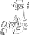
- FIGURE 1A is a perspective view of an operating room in which the present invention is deployed;
- FIGURE 1B is a block diagram of the image data manipulation of the system of FIGURE 1A;
- FIGURES 2A, 2B AND 2C illustrate the wand of FIGURES 1A AND 1B;
- FIGURE 3 is a detailed illustration of the locator assembly of FIGURE 1;
- FIGURE 4 is a diagrammatic illustration of a calibration procedure;
- FIGURES 5A AND 5B are diagrammatic illustrations of the wand and locator relationship;
- FIGURE 5C is a flow diagram of the wand location procedure;
- FIGURES 6A, 6B, 6C and 6D are illustrative of a coordinate transform between the coordinate system of the data and the patient.
- With reference to FIGURE 1A, a subject, such as a human patient, is received on an operating table or
other subject support 10 and appropriately positioned within the operating room. Aframe 12 is fixed to the patient support such that it is precisely positioned within the subject or subject support coordinate system. Mounting theframe 12 to the patient support permits the patient support to be turned, raised, lowered, wheeled to another location, or the like, without altering the patient coordinate system. Theframe 12 supports a plurality of emitter/receiver combinations 14 mounted at fixed, known locations thereon. Preferably, ahead clamp 16 or other means securely positions the patient's head or other portion of the subject under consideration in the subject support coordinate system. The frame is mounted at a fixed or selectable angle from vertical such that the frame is positionable more toward the patient, yet still focusing on the region of interest of the patient. - With continuing reference to FIGURE 1A and further reference to FIGURE 1B, an
operator console 18 houses acomputer system 20. Alternately, the computer system can be remotely located and connected with thecontrol console 18 by cabling. The computer system includes a three-dimensional data memory 22. The stored three-dimensional image data preferably contains a video pixel value for each voxel or point in a three-dimensional rectangular grid of points, preferably a 256 x 256 x 256 grid. When each image value represents one millimeter cube, the image data represents about a 25.6 centimeter cube through the patient with one millimeter resolution. Because the data is in a three-dimensional rectangular grid, selectable orthogonal and other oblique planes of the data can readily be withdrawn from the three-dimensional memory using conventional technology. A plane selecting means 24 selects various two-dimensional planes of pixel values from the three-dimensional memory for display. - In the preferred embodiment, the plane selecting means selects at least three planes: axial, sagittal, coronal, and oblique planes through a selectable point of the patient. The pixel values which lie on the selected axial, sagittal, coronal, and oblique planes are copied into
corresponding image memories video monitors 30 or other appropriate display means. - With continuing reference to FIGURE 1A and further reference to FIGURE 2A, in order to designate a position on the patient, the surgeon positions a
tip 40 of awand 42 at the desired location. The locator system locates the coordinate of the tip and the trajectory of the wand. More specifically, the wand includes a pair ofemitters first emitter 44 has a fixed, known distance ℓ₁ from thetip 40 and the second emitter has a fixed, known distance ℓ₂ from thefirst emitter 44. The wand is readily sterilized by conventional techniques. For simplicity of mathematical calculation, the two emitters and the tip are preferably in linear alignment. Optionally, as illustrated in FIGURE 2C, thewand 42 may have a jog 48 which enables the tip and the two emitters to be disposed along a central axis or pointing direction of the wand. - With reference to FIGURE 3, the
frame 12 includes not only the plurality of receivers,e.g. microphones 50 in the preferred ultrasonic embodiment, but also a plurality ofreference emitters 52. The reference receivers are each spaced along side edges of the frame from adjacent receivers ormicrophones 50 by distances S₁ and S₂. Preferably S₁=S₂=S. Each reference receiver is also spaced by a distance D across the frame from an oppositely disposedemitter 52. The emitters and the microphones are normally not coplanar with theframe 12. Preferably, both distances or range values D are equal in length. - In the preferred embodiment, the distance from the wand emitters to the frame, hence the position of the wand relative to the patient, is determined by the travel time of the sound. The velocity of the sound pulse through air is dependent upon both the temperature, the humidity, and the chemical composition of the air. These factors can and do vary significantly during an operation and from procedure to procedure. As shown in FIGURE 4, a calculation is performed to determine the speed of sound in the operating room. More specifically, a calibrating means 60 selectively pulses the
reference emitters 52, receives the signals atreceivers 50, and processes the elapsed time information in accordance with the procedure of FIGURE 4. More specifically, the calibration means 60 includes a step or means 62 for causing a first of thereference emitters 50 to emit a signal pulse. A step or means 64 acquires the range values D', i.e. the time required for the ultrasonic pulses to traverse the distance D. A step or means 66 causes this procedure to be repeated a preselected number of times, such as once for each of the four emitters illustrated in FIGURE 3. - Once the travel time between each emitter and receiver pair has been obtained a preselected number of times, a step or means 70 corrects the times for fixed machine delays. That is, there is a fixed, small delay between the time when the command is given to fire the
reference emitters 52 and the time that they actually produce a detectable ultrasonic signal. Analogously, there is a small delay between the time that the ultrasonic pulses reach the receiver ormicrophone 50 and the time that it becomes a measurable electrical signal received by the computer processor. These delays are subtracted from the times measured by step or means 64. An averaging means 72 averages the actual times after correction for the machine delays for transmission of the ultrasonic pulse between the transmitter and receiver. The time over the range values D' provide the most accurate results. A step or means 74 computes a calibration factor F indicative of the current speed of the ultrasound signal adjacent the patient in the operating room. In the preferred embodiment, the calibration factor F is a ratio of the sonically measured distance D' versus a precise mechanical measurement of the distance D. - With reference to FIGURES 5A, 5B, and 5C, a wand coordinate and
trajectory determining means 80 determines the position of the twoemitters emitter 44 to emit an ultrasonic signal. Thereceivers 50 on theframe 12 receive the ultrasonic signal at corresponding times L₁-L₄. A step or means 84 acquires and retains these times. A step or means 86 causes thesecond emitter 46 to transmit. A step or means 88 acquires the four times L₁-L₄ which are required for the ultrasonic signals to pass from the second emitter to themicrophones 50. The speed of ultrasonic transmission and accuracy of transmission times are such that these distances can be measured to within a millimeter or better. A step or means 90 causes the emitters to emit and corresponding data values L₁-L₄ to be acquired each of a plurality of times to improve digitation accuracy, e.g. two times. - A step or means 92 causes the calibration means 60 to perform the steps described in conjunction with FIGURE 4 in order to provide a current indication of the velocity of sound adjacent the patient. Of course, the calibration procedure of FIGURE 4 may be performed immediately before steps 82-88 or intermittently during the collection of several data values for averaging. A step or means 94 corrects the values values L₁-L₄ for the fixed machine delay discussed above in conjunction with step or means 70. A step or means 96 corrects each of the times L₁-L₄ that were required for the ultrasonic signals to travel from the first and
second emitters microphones 50 in accordance with the correction factor F determined by step or means 74. An averaging means 98 averages the delay and calibration corrected times L₁-L₄, hence distances between each of thewand emitters microphones 50. From these distances, provided at least threereceivers 50 are provided, a step or means 100 calculates the Cartesian coordinates (x₁,y₁,z₁) and (x₂,y₂,z₂) in the patient space for the twoemitters 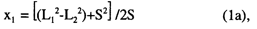


where S=S₁=S₂ as defined in FIGURE 3. Preferably, the three selected range values are the three shortest of L₁-L₄. Similar computations are calculated for x₂, y₂, and z₂ coordinates of the second emitter. A step or means 102 checks the validity of the measurement. More specifically, the known separation between the wand emitters is compared with the separation between the measured coordinates x₁y₁,z₁ and x₂,y₂,z₂ of the wand emitters, i.e.:
If the difference between the measured and known separations is greater than the acceptable error, e.g. 0.75 mm when measuring with a resolution of 1 mm, an erroneous measurement signal is given. The measurement is discarded and the surgeon or other user is flagged to perform themeasurement process 80 again. A step or means 104 from the coordinates of the twoemitters wand tip 40. - The tip coordinates x₀, y₀, z₀ are defined by:


- With reference to FIGURE 6, a transform means 110 transforms the coordinates of patient space into the coordinate system of the image data and vice versa. More specifically, prior to the imaging, three or more fiducials or markers are affixed at three or more spaced points on the patient's head. The fiducials are visible in the imaging medium selected such that they show up as readily
identifiable dots 112 in the resultant image data. In thepreferred embodiment, the fiducials are markers orsmall beads 114 that are injected with radiation opaque and magnetic resonance excitable materials. A small dot or tattoo is made on the patient's skin and a fiducial is glued to each dot. This enables the position of the fiducials to be denoted even if the fiducials are removed in the interval between the collection of the image data and the surgical procedure. Alternately, portions of the markers can be portions of the patient's anatomy which are readily identifiable in both patient and image space, e.g. the tip of the nose. To align the images of the fiducials with the fiducial positions in patient space, the tip of the wand is placed on each fiducial or tattooed marker point. The coordinates in patient space of each fiducial are determined with the procedure described in conjunction with FIGURES 5A-5C. - The position of the three or more fiducials on the patient's scalp are compared with the relative position of the
pixels 112 in the image space. The patient space coordinates ofmarks 114 on the patient's skull in the coordinate system of the patient support are measured. A like coordinate system through thepixels 112 is defined and compared to the patient space coordinate system. The translation and rotational relationship between image space and patient space coordinate systems is determined. With reference to FIGURE 6A, the position of the patient in operating room space (x,y,z) and the relative position in image space (x',y',z') are determined. That is, two coordinate systems are defined. The translation means first determines the offset xoffset, yoffset, zoffset between thebarycenters - With reference to FIGURE 6B, translating the origins of the two coordinate systems into alignment, however, is not the complete correction. Rather, the coordinate systems are normally also rotated relative to each other about all three axes whose origin is at the barycenter. As illustrated in FIGURES 6B, 6C, and 6D, the angle of rotation in the (y,z), (x,z), and (x,y) planes are determined. Having made these determinations, it is a simple matter to transform the patient support space coordinates into the image space coordinates and, conversely, to rotate the image space coordinates into patient space coordinates. The wand coordinate means 80 is connected through the transform means 110 with one of the
plane selecting means 24 and thevideo processor 28 to cause a marker, e.g. cross hairs, to be displayed on themonitors 30 at the coordinates of the wand tip. This enables the surgeon to coordinate specific points on the patient or in the incision with the images. - Having aligned the data and patient coordinate systems, numerous techniques can be performed in addition to surgery planning and verification. One can denote two locations in the patient and have them displayed on the monitor in data space. Because the measurement scale in data space is fixed, the distance between the two points is readily determined. The wand can be used to denote points on the patient and mark corresponding points in data space. The marked points can denote electrode locations for example. The present system can be used for out-patient procedures, examinations, and the like, of various parts of the patient's anatomy. Further, more than one set of diagnostic data can be coordinated with the patient. Optionally, an additional three-dimensional data memory 22' may store additional diagnostic data, e.g. from another modality, from the same modality, but at different time or with different imaging characteristics, or the like. Once both sets of diagnostic data are coordinated with the patient coordinate system, they are coordinated with each other.
Claims (23)
- A position determining system comprising: a subject support (10); a means (16) for securing a preselected portion of a subject to the subject support(10); a frame assembly (12) which mounts at least three receivers (50) in a fixed relationship to the subject support (10) closely adjacent the means (16) for securing a portion of the subject to the subject support(10); at least one reference emitter (52) mounted a fixed, known distance from the receivers (50), the reference emitter (52) emitting a reference signal which travels from the reference emitter (52) the fixed distance to the receivers(50); a calibration means (60) for measuring a reference travel time of the reference signal over the fixed distance; a wand (42) having a pointer(40) and at least two emitters (44,46) mounted thereto, the two wand emitters (44,46) selectively emitting wand signals which are received by the at least three receivers(50); a wand position determining means (80) for determining a position of the wand pointer (40) by measuring wand signal travel times of the wand signals between the two wand emitters (44,46) and the at least three receivers (50), the wand position determining means (80) being connected with the calibration means (60) for calibrating the wand signal travel times with the reference travel time.
- A system according to claim 1 further including: a three-dimensional image memory means for storing image data indicative of a three-dimensional region of the portion of the subject which is secured to the subject support means; a plane selecting means for selecting planar slices of data from the three-dimensional, image memory means; a display means for converting the selected slices of data from the plane selecting means into human-readable displays; a transform means for transforming a position of the wand pointer into a coordinate system of the image data stored in the three-dimensional image memory means, the transform means being operatively connected with the plane selecting means such that the displayed images have a preselected relationship to the position of the wand pointer.
- A system according to claim 2 wherein the frame assembly is mounted directly to the subject support to be movable therewith such that movement of the subject support does not alter the subject coordinate system.
- A system according to claim 2 wherein the frame assembly is mounted to the subject support angled from a perpendicular relationship to focus on the secured subject region, even when mounted away from the secured region of the subject.
- A system according to claim 2 wherein the subject is a human patient.
- A system according to claim 2 further including: at least three markers disposed on the selected subject portion, the markers having been secured to the subject when the three-dimensional image data was acquired such that locations of the three markers are identifiable in the three-dimensional image data, the markers being identifiable on the surface of the subject; and a transform calculating means for calculating a transform between positions of the markers on the subject denoted by selectively placing the wand pointer on each of the markers with the marker locations in the three-dimensional image data, whereby translational and rotational relationships between a subject space coordinate system and a three-dimensional image data space coordinate system.
- A system according to claim 6 wherein the markers contain materials which are visible in both magnetic resonance and CT imaging techniques such that the same markers can be used for both CT and magnetic resonance examinations.
- A system according to claim 1 wherein a plurality of reference emitters are mounted to the frame in fixed relationships to the receivers.
- A system according to claim 1 wherein the wand includes a tip portion, a portion extending along a pointing axis of the wand, and an offset portion which is offset from the pointing axis of the wand, the wand emitters being mounted in a spaced relationship to the offset section in alignment with the pointing axis of the wand such that the wand tip and the two actuators are co-linear.
- A system according to any one of the preceding claims which is a stereotaxy system.
- A position determining method comprising: a) securing a portion of a subject to a subject supporting surface in close proximity to at least three signal receivers that are mounted in a fixed relationship to the subject supporting surface; b) positioning a wand to designate selected locations on the subject portion, the wand having at least two wand emitters mounted thereon for selectively emitting signals which are received by the receivers; c) actuating the wand emitters to emit wand signals; d) from the wand emitter signals, calculating coordinates of the wand emitters in a coordinate system of the subject support; e) comparing a calculated distance between calculated wand emitter coordinates and a physical distance between the wand emitters; f) in response to the difference between the calculated distance and the physical distance exceeding a preselected standard, providing an unacceptable measurement signal.
- A position determining method comprising: a) securing a portion of a subject to a subject supporting surface in close proximity to at least three signal receivers that are mounted in a fixed relationship to the subject supporting surface, a reference signal emitter being fixedly mounted at a fixed, known distance from the plurality of receivers; b) positioning a wand to designate selected locations on the subject portion, the wand having at least two wand emitters mounted thereon for selectively emitting signals which are received by the receivers; c) actuating the wand emitters individually and the reference emitter in close temporal proximity to emit wand and reference signals; d) measuring travel durations for the wand and reference signals to travel from each of the wand emitters to the receivers and from the reference emitter to the receivers; e) from the travel times, calculating coordinates of the locations designated by the wand in a coordinate system of the subject support.
- A method according to claim 12 further including: calculating a distance between the wand emitters; comparing the calculated distance between the wand emitters with a premeasured physical distance between the emitters to verify an acceptable accuracy of the measurement.
- A method according to claim 13 further including sterilizing the wand.
- A method according to claim 13 further including repeating steps (b)-(e) with the wand in a second location to calculate coordinates of the second location and further including from the coordinates of the first and second locations, determining a distance therebetween.
- A method according to claim 13 wherein the subject support coordinates system coordinates calculating step includes: determining travel times between the wand emitters and the plurality of receivers, the relative travel times between each emitter and the receivers being indicative of a location of each emitter; correcting at least one of (i) the relative travel times between the wand emitters and the receivers and (ii) the determined positions of the emitters in accordance with the travel time between the reference emitter and at least one of the receivers, whereby the position of the wand is corrected for variations in signal transmission speed attributable to changes in temperature, humidity, and other conditions adjacent the subject.
- A method according to claim 16 wherein: the two wand emitters are actuated alternately a plurality of times; the reference emitter is actuated at least once; the travel times are adjusted for delays between (i) actuation of the emitter and emission of the signal and between (ii) the signal reaching the receiver and being converted into an electronic timing signal; the correcting step includes correcting the travel times between the wand emitters and the receivers in accordance with the travel time between the reference emitter and the receivers; and further including: averaging the corrected travel times and determining coordinates for each wand emitter; from the wand emitter coordinates calculating a coordinate of a tip portion of the wand.
- A method according to claim 13 further including: conducting a first non-invasive diagnostic examination of the subject portion and generating three-dimensional electronic image data thereof; storing the three-dimensional image data; determining a transform between the first image data coordinate system and the subject support coordinate system.
- A method according to claim 18 further including: conducting a second non-invasive diagnostic examination of the subject portion and generating three-dimensional electronic image data thereof; storing the second examination three-dimensional image data; determining a transform between the second image data coordinate system and the subject support coordinate system; determining a relationship between the first and second image data coordinate systems.
- A method according to claim 18 wherein the transform determining step includes: mounting at least three non-invasive examination visible markers to the subject portion such that the three-dimensional diagnostic image data includes indications of the at least three markers; with the wand designating a position of each of the three markers and determining a coordinate of each marker in the subject support coordinate system; comparing the coordinates of the markers in the subject support coordinate system and a position of the marker indications in the image data coordinate system to determine at least a translation offset between the image data and subject support coordinate systems and a rotational offset between the subject support and image data coordinate systems.
- A method according to claim 18 wherein the subject is a living patient.
- A method according to claim 12 wherein the subject portion is a head of the patient.
- A method according to any one of claims 11 to 22 which is a stereotaxy method.
Applications Claiming Priority (2)
| Application Number | Priority Date | Filing Date | Title |
|---|---|---|---|
| US983390 | 1992-11-30 | ||
| US07/983,390 US5309913A (en) | 1992-11-30 | 1992-11-30 | Frameless stereotaxy system |
Publications (3)
| Publication Number | Publication Date |
|---|---|
| EP0600610A2 true EP0600610A2 (en) | 1994-06-08 |
| EP0600610A3 EP0600610A3 (en) | 1995-06-07 |
| EP0600610B1 EP0600610B1 (en) | 1998-06-03 |
Family
ID=25529928
Family Applications (1)
| Application Number | Title | Priority Date | Filing Date |
|---|---|---|---|
| EP93308694A Expired - Lifetime EP0600610B1 (en) | 1992-11-30 | 1993-11-01 | A position determining system and method |
Country Status (4)
| Country | Link |
|---|---|
| US (1) | US5309913A (en) |
| EP (1) | EP0600610B1 (en) |
| JP (1) | JPH07148180A (en) |
| DE (1) | DE69318944T2 (en) |
Cited By (36)
| Publication number | Priority date | Publication date | Assignee | Title |
|---|---|---|---|---|
| EP0757255A2 (en) * | 1995-07-27 | 1997-02-05 | Gec-Marconi Limited | Imaging systems |
| EP0825830A1 (en) * | 1995-04-10 | 1998-03-04 | Compass International Incorporated | Magnetic field digitizer for stereotactic surgery |
| WO1998038919A2 (en) * | 1997-03-04 | 1998-09-11 | Biotrack, Inc. | Medical sensing and imaging system |
| EP0951874A3 (en) * | 1994-09-15 | 2000-06-14 | Visualization Technology, Inc. | Position tracking and imaging system for use in medical applications using a reference unit secured to a patients head |
| EP1034461A2 (en) * | 1997-11-27 | 2000-09-13 | Ultra-Guide Ltd. | System and method for guiding the movements of a device to a target particularly for medical applications |
| WO2000057132A1 (en) * | 1999-03-22 | 2000-09-28 | Arc Second, Inc. | Method for creating a user-selectable coordinate frame |
| EP0919203A3 (en) * | 1997-11-28 | 2000-11-29 | Picker International, Inc. | Frameless stereotactic surgical apparatus |
| EP1115328A1 (en) * | 1998-09-24 | 2001-07-18 | Super Dimension Ltd. | System and method for determining the location of a catheter during an intra-body medical procedure |
| US6490477B1 (en) | 1998-05-05 | 2002-12-03 | Koninklijke Philips Electronics N.V. | Imaging modality for image guided surgery |
| US6662103B1 (en) | 1999-03-22 | 2003-12-09 | Arc Second Inc. | Method and system for creating a user-selectable arbitrary coordinate frame |
| EP1380266A1 (en) * | 1994-09-15 | 2004-01-14 | OEC Medical Systems, Inc. | Position tracking and imaging system for use in medical applications using a reference unit secured to patient's head |
| US6731966B1 (en) | 1997-03-04 | 2004-05-04 | Zachary S. Spigelman | Systems and methods for targeting a lesion |
| EP1481635A2 (en) * | 1996-02-15 | 2004-12-01 | Biosense Webster, Inc. | Movable transmit or receive coils for location system |
| EP1749550A1 (en) * | 2005-08-04 | 2007-02-07 | Institut Curie | Method and apparatus for applying radiotherapy |
| US7233820B2 (en) | 2002-04-17 | 2007-06-19 | Superdimension Ltd. | Endoscope structures and techniques for navigating to a target in branched structure |
| US8452068B2 (en) | 2008-06-06 | 2013-05-28 | Covidien Lp | Hybrid registration method |
| US8473032B2 (en) | 2008-06-03 | 2013-06-25 | Superdimension, Ltd. | Feature-based registration method |
| US8473200B1 (en) * | 2004-10-25 | 2013-06-25 | A9.com | Displaying location-specific images on a mobile device |
| US8663088B2 (en) | 2003-09-15 | 2014-03-04 | Covidien Lp | System of accessories for use with bronchoscopes |
| US8764725B2 (en) | 2004-02-09 | 2014-07-01 | Covidien Lp | Directional anchoring mechanism, method and applications thereof |
| US8905920B2 (en) | 2007-09-27 | 2014-12-09 | Covidien Lp | Bronchoscope adapter and method |
| US8932207B2 (en) | 2008-07-10 | 2015-01-13 | Covidien Lp | Integrated multi-functional endoscopic tool |
| US9055881B2 (en) | 2004-04-26 | 2015-06-16 | Super Dimension Ltd. | System and method for image-based alignment of an endoscope |
| US9575140B2 (en) | 2008-04-03 | 2017-02-21 | Covidien Lp | Magnetic interference detection system and method |
| US10418705B2 (en) | 2016-10-28 | 2019-09-17 | Covidien Lp | Electromagnetic navigation antenna assembly and electromagnetic navigation system including the same |
| US10426555B2 (en) | 2015-06-03 | 2019-10-01 | Covidien Lp | Medical instrument with sensor for use in a system and method for electromagnetic navigation |
| US10446931B2 (en) | 2016-10-28 | 2019-10-15 | Covidien Lp | Electromagnetic navigation antenna assembly and electromagnetic navigation system including the same |
| US10517505B2 (en) | 2016-10-28 | 2019-12-31 | Covidien Lp | Systems, methods, and computer-readable media for optimizing an electromagnetic navigation system |
| US10582834B2 (en) | 2010-06-15 | 2020-03-10 | Covidien Lp | Locatable expandable working channel and method |
| US10615500B2 (en) | 2016-10-28 | 2020-04-07 | Covidien Lp | System and method for designing electromagnetic navigation antenna assemblies |
| US10638952B2 (en) | 2016-10-28 | 2020-05-05 | Covidien Lp | Methods, systems, and computer-readable media for calibrating an electromagnetic navigation system |
| US10722311B2 (en) | 2016-10-28 | 2020-07-28 | Covidien Lp | System and method for identifying a location and/or an orientation of an electromagnetic sensor based on a map |
| US10751126B2 (en) | 2016-10-28 | 2020-08-25 | Covidien Lp | System and method for generating a map for electromagnetic navigation |
| US10792106B2 (en) | 2016-10-28 | 2020-10-06 | Covidien Lp | System for calibrating an electromagnetic navigation system |
| US10952593B2 (en) | 2014-06-10 | 2021-03-23 | Covidien Lp | Bronchoscope adapter |
| US11382573B2 (en) | 2014-07-02 | 2022-07-12 | Covidien Lp | System and method of providing distance and orientation feedback while navigating in 3D |
Families Citing this family (194)
| Publication number | Priority date | Publication date | Assignee | Title |
|---|---|---|---|---|
| US5251127A (en) * | 1988-02-01 | 1993-10-05 | Faro Medical Technologies Inc. | Computer-aided surgery apparatus |
| US6331180B1 (en) | 1988-05-03 | 2001-12-18 | Sherwood Services Ag | Target-centered stereotaxtic surgical arc system with reorientatable arc axis |
| FR2652928B1 (en) | 1989-10-05 | 1994-07-29 | Diadix Sa | INTERACTIVE LOCAL INTERVENTION SYSTEM WITHIN A AREA OF A NON-HOMOGENEOUS STRUCTURE. |
| US6347240B1 (en) | 1990-10-19 | 2002-02-12 | St. Louis University | System and method for use in displaying images of a body part |
| ATE196234T1 (en) | 1990-10-19 | 2000-09-15 | Univ St Louis | LOCALIZATION SYSTEM FOR A SURGICAL PROBE FOR USE ON THE HEAD |
| US6405072B1 (en) * | 1991-01-28 | 2002-06-11 | Sherwood Services Ag | Apparatus and method for determining a location of an anatomical target with reference to a medical apparatus |
| US6006126A (en) | 1991-01-28 | 1999-12-21 | Cosman; Eric R. | System and method for stereotactic registration of image scan data |
| US5330485A (en) * | 1991-11-01 | 1994-07-19 | Clayman David A | Cerebral instrument guide frame and procedures utilizing it |
| US5603318A (en) * | 1992-04-21 | 1997-02-18 | University Of Utah Research Foundation | Apparatus and method for photogrammetric surgical localization |
| ES2115776T3 (en) | 1992-08-14 | 1998-07-01 | British Telecomm | POSITION LOCATION SYSTEM. |
| US6757557B1 (en) | 1992-08-14 | 2004-06-29 | British Telecommunications | Position location system |
| US5517990A (en) * | 1992-11-30 | 1996-05-21 | The Cleveland Clinic Foundation | Stereotaxy wand and tool guide |
| US5483961A (en) * | 1993-03-19 | 1996-01-16 | Kelly; Patrick J. | Magnetic field digitizer for stereotactic surgery |
| EP1219259B1 (en) | 1993-04-22 | 2003-07-16 | Image Guided Technologies, Inc. | System for locating relative positions of objects |
| CA2161430C (en) * | 1993-04-26 | 2001-07-03 | Richard D. Bucholz | System and method for indicating the position of a surgical probe |
| US5558091A (en) * | 1993-10-06 | 1996-09-24 | Biosense, Inc. | Magnetic determination of position and orientation |
| US6120465A (en) | 1994-01-24 | 2000-09-19 | Radionics Software Applications, Inc. | Virtual probe for a stereotactic digitizer for use in surgery |
| US20040015176A1 (en) * | 1994-06-20 | 2004-01-22 | Cosman Eric R. | Stereotactic localizer system with dental impression |
| EP0774929A4 (en) * | 1994-07-22 | 2000-09-27 | Univ Washington | Methods for stereotactic implantation |
| US5829444A (en) | 1994-09-15 | 1998-11-03 | Visualization Technology, Inc. | Position tracking and imaging system for use in medical applications |
| US6978166B2 (en) * | 1994-10-07 | 2005-12-20 | Saint Louis University | System for use in displaying images of a body part |
| AU3950595A (en) * | 1994-10-07 | 1996-05-06 | St. Louis University | Surgical navigation systems including reference and localization frames |
| DE69530355D1 (en) * | 1994-11-28 | 2003-05-22 | Ohio State University Columbus | Medical intervention device |
| US5682890A (en) * | 1995-01-26 | 1997-11-04 | Picker International, Inc. | Magnetic resonance stereotactic surgery with exoskeleton tissue stabilization |
| US5588430A (en) * | 1995-02-14 | 1996-12-31 | University Of Florida Research Foundation, Inc. | Repeat fixation for frameless stereotactic procedure |
| US5868673A (en) * | 1995-03-28 | 1999-02-09 | Sonometrics Corporation | System for carrying out surgery, biopsy and ablation of a tumor or other physical anomaly |
| US5592939A (en) | 1995-06-14 | 1997-01-14 | Martinelli; Michael A. | Method and system for navigating a catheter probe |
| KR19990029038A (en) * | 1995-07-16 | 1999-04-15 | 요아브 빨띠에리 | Free aiming of needle ceramic |
| US6351659B1 (en) | 1995-09-28 | 2002-02-26 | Brainlab Med. Computersysteme Gmbh | Neuro-navigation system |
| DE19536180C2 (en) * | 1995-09-28 | 2003-05-08 | Brainlab Ag | Methods and devices for locating an instrument |
| US5769861A (en) * | 1995-09-28 | 1998-06-23 | Brainlab Med. Computersysteme Gmbh | Method and devices for localizing an instrument |
| CH691569A5 (en) * | 1995-10-12 | 2001-08-31 | Zeiss Carl | Medical therapy and / or diagnostic device with sterilizable Positionserfassungsaufsetzteil. |
| US5772594A (en) * | 1995-10-17 | 1998-06-30 | Barrick; Earl F. | Fluoroscopic image guided orthopaedic surgery system with intraoperative registration |
| WO1997029678A2 (en) | 1996-02-15 | 1997-08-21 | Biosense Inc. | Catheter calibration and usage monitoring system |
| EP0888086B1 (en) | 1996-02-15 | 2005-07-27 | Biosense Webster, Inc. | Excavation probe |
| DE69733249T8 (en) | 1996-02-15 | 2006-04-27 | Biosense Webster, Inc., Diamond Bar | DETERMINATION OF THE EXACT POSITION OF ENDOSCOPES |
| US6453190B1 (en) | 1996-02-15 | 2002-09-17 | Biosense, Inc. | Medical probes with field transducers |
| CA2246284C (en) | 1996-02-15 | 2008-01-29 | Biosense, Inc. | Catheter with lumen |
| US6618612B1 (en) | 1996-02-15 | 2003-09-09 | Biosense, Inc. | Independently positionable transducers for location system |
| EP0910300B1 (en) | 1996-02-15 | 2003-12-03 | Biosense, Inc. | Site marking probe |
| AU704129B2 (en) | 1996-02-27 | 1999-04-15 | Biosense, Inc. | Location system with field actuation sequences |
| US6167145A (en) | 1996-03-29 | 2000-12-26 | Surgical Navigation Technologies, Inc. | Bone navigation system |
| US5782765A (en) * | 1996-04-25 | 1998-07-21 | Medtronic, Inc. | Medical positioning system |
| AU722748B2 (en) | 1996-05-06 | 2000-08-10 | Biosense, Inc. | Radiator calibration |
| US6226418B1 (en) | 1997-11-07 | 2001-05-01 | Washington University | Rapid convolution based large deformation image matching via landmark and volume imagery |
| US6408107B1 (en) | 1996-07-10 | 2002-06-18 | Michael I. Miller | Rapid convolution based large deformation image matching via landmark and volume imagery |
| US6296613B1 (en) | 1997-08-22 | 2001-10-02 | Synthes (U.S.A.) | 3D ultrasound recording device |
| US5951571A (en) * | 1996-09-19 | 1999-09-14 | Surgical Navigation Specialist Inc. | Method and apparatus for correlating a body with an image of the body |
| US6142937A (en) * | 1996-10-11 | 2000-11-07 | Carl-Zeiss-Stiftung | Medical therapeutic and/or diagnostic appliance with a sterilizable position sensing attachment |
| US5902239A (en) * | 1996-10-30 | 1999-05-11 | U.S. Philips Corporation | Image guided surgery system including a unit for transforming patient positions to image positions |
| US7302288B1 (en) * | 1996-11-25 | 2007-11-27 | Z-Kat, Inc. | Tool position indicator |
| US6314310B1 (en) | 1997-02-14 | 2001-11-06 | Biosense, Inc. | X-ray guided surgical location system with extended mapping volume |
| US5841830A (en) * | 1997-02-19 | 1998-11-24 | Picker International, Inc. | 3D CT fluoroscopy |
| USD422706S (en) * | 1997-04-30 | 2000-04-11 | Surgical Navigation Technologies | Biopsy guide tube |
| US6267769B1 (en) | 1997-05-15 | 2001-07-31 | Regents Of The Universitiy Of Minnesota | Trajectory guide method and apparatus for use in magnetic resonance and computerized tomographic scanners |
| US6752812B1 (en) | 1997-05-15 | 2004-06-22 | Regent Of The University Of Minnesota | Remote actuation of trajectory guide |
| US6434507B1 (en) | 1997-09-05 | 2002-08-13 | Surgical Navigation Technologies, Inc. | Medical instrument and method for use with computer-assisted image guided surgery |
| US6226548B1 (en) | 1997-09-24 | 2001-05-01 | Surgical Navigation Technologies, Inc. | Percutaneous registration apparatus and method for use in computer-assisted surgical navigation |
| US6081336A (en) * | 1997-09-26 | 2000-06-27 | Picker International, Inc. | Microscope calibrator |
| US6147480A (en) * | 1997-10-23 | 2000-11-14 | Biosense, Inc. | Detection of metal disturbance |
| USD420132S (en) * | 1997-11-03 | 2000-02-01 | Surgical Navigation Technologies | Drill guide |
| US6021343A (en) | 1997-11-20 | 2000-02-01 | Surgical Navigation Technologies | Image guided awl/tap/screwdriver |
| US6035228A (en) * | 1997-11-28 | 2000-03-07 | Picker International, Inc. | Frameless stereotactic arm apparatus and method of using same |
| US6064904A (en) * | 1997-11-28 | 2000-05-16 | Picker International, Inc. | Frameless stereotactic CT scanner with virtual needle display for planning image guided interventional procedures |
| US5967982A (en) * | 1997-12-09 | 1999-10-19 | The Cleveland Clinic Foundation | Non-invasive spine and bone registration for frameless stereotaxy |
| US6348058B1 (en) | 1997-12-12 | 2002-02-19 | Surgical Navigation Technologies, Inc. | Image guided spinal surgery guide, system, and method for use thereof |
| US6223066B1 (en) | 1998-01-21 | 2001-04-24 | Biosense, Inc. | Optical position sensors |
| DE59814196D1 (en) | 1998-06-22 | 2008-04-30 | Ao Technology Ag | Fiducial matching mittels fiducial-schraube |
| US6118845A (en) | 1998-06-29 | 2000-09-12 | Surgical Navigation Technologies, Inc. | System and methods for the reduction and elimination of image artifacts in the calibration of X-ray imagers |
| US6477400B1 (en) * | 1998-08-20 | 2002-11-05 | Sofamor Danek Holdings, Inc. | Fluoroscopic image guided orthopaedic surgery system with intraoperative registration |
| US6482182B1 (en) | 1998-09-03 | 2002-11-19 | Surgical Navigation Technologies, Inc. | Anchoring system for a brain lead |
| US6195577B1 (en) | 1998-10-08 | 2001-02-27 | Regents Of The University Of Minnesota | Method and apparatus for positioning a device in a body |
| AU6421599A (en) | 1998-10-09 | 2000-05-01 | Surgical Navigation Technologies, Inc. | Image guided vertebral distractor |
| US6373240B1 (en) | 1998-10-15 | 2002-04-16 | Biosense, Inc. | Metal immune system for tracking spatial coordinates of an object in the presence of a perturbed energy field |
| US6633686B1 (en) | 1998-11-05 | 2003-10-14 | Washington University | Method and apparatus for image registration using large deformation diffeomorphisms on a sphere |
| US6285902B1 (en) | 1999-02-10 | 2001-09-04 | Surgical Insights, Inc. | Computer assisted targeting device for use in orthopaedic surgery |
| US7590441B2 (en) * | 1999-03-11 | 2009-09-15 | Biosense, Inc. | Invasive medical device with position sensing and display |
| US7575550B1 (en) | 1999-03-11 | 2009-08-18 | Biosense, Inc. | Position sensing based on ultrasound emission |
| US7174201B2 (en) * | 1999-03-11 | 2007-02-06 | Biosense, Inc. | Position sensing system with integral location pad and position display |
| US7549960B2 (en) | 1999-03-11 | 2009-06-23 | Biosense, Inc. | Implantable and insertable passive tags |
| US7558616B2 (en) * | 1999-03-11 | 2009-07-07 | Biosense, Inc. | Guidance of invasive medical procedures using implantable tags |
| WO2000054687A1 (en) | 1999-03-17 | 2000-09-21 | Synthes Ag Chur | Imaging and planning device for ligament graft placement |
| US6470207B1 (en) | 1999-03-23 | 2002-10-22 | Surgical Navigation Technologies, Inc. | Navigational guidance via computer-assisted fluoroscopic imaging |
| US6491699B1 (en) | 1999-04-20 | 2002-12-10 | Surgical Navigation Technologies, Inc. | Instrument guidance method and system for image guided surgery |
| WO2000063719A1 (en) | 1999-04-20 | 2000-10-26 | Synthes Ag Chur | Device for the percutaneous obtainment of 3d-coordinates on the surface of a human or animal organ |
| DE59905962D1 (en) * | 1999-05-03 | 2003-07-17 | Synthes Ag | POSITION DETECTING DEVICE WITH AID TO DETERMINE THE DIRECTION OF THE GRAVITY VECTOR |
| US6314311B1 (en) | 1999-07-28 | 2001-11-06 | Picker International, Inc. | Movable mirror laser registration system |
| US6406482B1 (en) | 1999-09-13 | 2002-06-18 | The Ohio State University | Stereotactic apparatus and methods |
| DE19947328B4 (en) * | 1999-10-01 | 2006-06-14 | Siemens Ag | Medical imaging diagnostic device |
| DE19947422A1 (en) | 1999-10-01 | 2001-05-03 | Siemens Ag | Medical diagnostic imaging device |
| US6747539B1 (en) | 1999-10-28 | 2004-06-08 | Michael A. Martinelli | Patient-shielding and coil system |
| US6235038B1 (en) | 1999-10-28 | 2001-05-22 | Medtronic Surgical Navigation Technologies | System for translation of electromagnetic and optical localization systems |
| US6474341B1 (en) | 1999-10-28 | 2002-11-05 | Surgical Navigation Technologies, Inc. | Surgical communication and power system |
| AU1240801A (en) | 1999-10-28 | 2001-05-08 | Enterprise Medical Technology, Inc. | Coil structures and methods for generating magnetic fields |
| US7366562B2 (en) | 2003-10-17 | 2008-04-29 | Medtronic Navigation, Inc. | Method and apparatus for surgical navigation |
| US8239001B2 (en) | 2003-10-17 | 2012-08-07 | Medtronic Navigation, Inc. | Method and apparatus for surgical navigation |
| US6381485B1 (en) | 1999-10-28 | 2002-04-30 | Surgical Navigation Technologies, Inc. | Registration of human anatomy integrated for electromagnetic localization |
| US6379302B1 (en) | 1999-10-28 | 2002-04-30 | Surgical Navigation Technologies Inc. | Navigation information overlay onto ultrasound imagery |
| US6493573B1 (en) | 1999-10-28 | 2002-12-10 | Winchester Development Associates | Method and system for navigating a catheter probe in the presence of field-influencing objects |
| US8644907B2 (en) | 1999-10-28 | 2014-02-04 | Medtronic Navigaton, Inc. | Method and apparatus for surgical navigation |
| US11331150B2 (en) | 1999-10-28 | 2022-05-17 | Medtronic Navigation, Inc. | Method and apparatus for surgical navigation |
| US6499488B1 (en) | 1999-10-28 | 2002-12-31 | Winchester Development Associates | Surgical sensor |
| US6261299B1 (en) | 1999-11-26 | 2001-07-17 | The Ohio State University | Stereotactic apparatus and methods |
| WO2001064124A1 (en) | 2000-03-01 | 2001-09-07 | Surgical Navigation Technologies, Inc. | Multiple cannula image guided tool for image guided procedures |
| US7366561B2 (en) * | 2000-04-07 | 2008-04-29 | Medtronic, Inc. | Robotic trajectory guide |
| US6535756B1 (en) | 2000-04-07 | 2003-03-18 | Surgical Navigation Technologies, Inc. | Trajectory storage apparatus and method for surgical navigation system |
| US7660621B2 (en) | 2000-04-07 | 2010-02-09 | Medtronic, Inc. | Medical device introducer |
| US7085400B1 (en) | 2000-06-14 | 2006-08-01 | Surgical Navigation Technologies, Inc. | System and method for image based sensor calibration |
| GB0015683D0 (en) * | 2000-06-28 | 2000-08-16 | Depuy Int Ltd | Apparatus for positioning a surgical instrument |
| US6484118B1 (en) | 2000-07-20 | 2002-11-19 | Biosense, Inc. | Electromagnetic position single axis system |
| US6902569B2 (en) | 2000-08-17 | 2005-06-07 | Image-Guided Neurologics, Inc. | Trajectory guide with instrument immobilizer |
| US6921406B1 (en) | 2001-04-19 | 2005-07-26 | The Ohio State University | Stereotactic apparatus and methods |
| US6533794B2 (en) | 2001-04-19 | 2003-03-18 | The Ohio State University | Simplified stereotactic apparatus and methods |
| US6636757B1 (en) | 2001-06-04 | 2003-10-21 | Surgical Navigation Technologies, Inc. | Method and apparatus for electromagnetic navigation of a surgical probe near a metal object |
| US6947786B2 (en) * | 2002-02-28 | 2005-09-20 | Surgical Navigation Technologies, Inc. | Method and apparatus for perspective inversion |
| US6990368B2 (en) | 2002-04-04 | 2006-01-24 | Surgical Navigation Technologies, Inc. | Method and apparatus for virtual digital subtraction angiography |
| US7998062B2 (en) | 2004-03-29 | 2011-08-16 | Superdimension, Ltd. | Endoscope structures and techniques for navigating to a target in branched structure |
| AR039475A1 (en) * | 2002-05-01 | 2005-02-23 | Wyeth Corp | 6-ALQUILIDEN-PENEMS TRICICLICOS AS BETA-LACTAMASA INHIBITORS |
| WO2003094702A2 (en) * | 2002-05-13 | 2003-11-20 | The Ohio State University Research Foundation | Instrument-holding projection imaging vector guide and method of use |
| US7704260B2 (en) | 2002-09-17 | 2010-04-27 | Medtronic, Inc. | Low profile instrument immobilizer |
| US7166114B2 (en) | 2002-09-18 | 2007-01-23 | Stryker Leibinger Gmbh & Co Kg | Method and system for calibrating a surgical tool and adapter thereof |
| WO2004046754A2 (en) * | 2002-11-14 | 2004-06-03 | General Electric Medical Systems Global Technology Company, Llc | Interchangeable localizing devices for use with tracking systems |
| US7697972B2 (en) | 2002-11-19 | 2010-04-13 | Medtronic Navigation, Inc. | Navigation system for cardiac therapies |
| US7599730B2 (en) | 2002-11-19 | 2009-10-06 | Medtronic Navigation, Inc. | Navigation system for cardiac therapies |
| US7945309B2 (en) | 2002-11-22 | 2011-05-17 | Biosense, Inc. | Dynamic metal immunity |
| DE10256659A1 (en) * | 2002-12-04 | 2004-07-08 | Siemens Ag | Input device for orientating a 3D medical image has means for selecting a reference point and means for fixing a viewing direction and setting a scale |
| US7636596B2 (en) | 2002-12-20 | 2009-12-22 | Medtronic, Inc. | Organ access device and method |
| US7660623B2 (en) | 2003-01-30 | 2010-02-09 | Medtronic Navigation, Inc. | Six degree of freedom alignment display for medical procedures |
| US7542791B2 (en) | 2003-01-30 | 2009-06-02 | Medtronic Navigation, Inc. | Method and apparatus for preplanning a surgical procedure |
| US7559935B2 (en) * | 2003-02-20 | 2009-07-14 | Medtronic, Inc. | Target depth locators for trajectory guide for introducing an instrument |
| US7896889B2 (en) | 2003-02-20 | 2011-03-01 | Medtronic, Inc. | Trajectory guide with angled or patterned lumens or height adjustment |
| CN101669831B (en) * | 2003-05-08 | 2013-09-25 | 株式会社日立医药 | Reference image display method |
| US7433728B2 (en) | 2003-05-29 | 2008-10-07 | Biosense, Inc. | Dynamic metal immunity by hysteresis |
| US7974680B2 (en) * | 2003-05-29 | 2011-07-05 | Biosense, Inc. | Hysteresis assessment for metal immunity |
| WO2004107959A2 (en) * | 2003-05-30 | 2004-12-16 | Schaerer Mayfield Usa, Inc. | Stylus for surgical navigation system |
| US7236358B2 (en) * | 2003-06-11 | 2007-06-26 | Hewlett-Packard Development Company, L.P. | Computer system |
| US7321228B2 (en) * | 2003-07-31 | 2008-01-22 | Biosense Webster, Inc. | Detection of metal disturbance in a magnetic tracking system |
| US7313430B2 (en) | 2003-08-28 | 2007-12-25 | Medtronic Navigation, Inc. | Method and apparatus for performing stereotactic surgery |
| US7835778B2 (en) | 2003-10-16 | 2010-11-16 | Medtronic Navigation, Inc. | Method and apparatus for surgical navigation of a multiple piece construct for implantation |
| US7840253B2 (en) | 2003-10-17 | 2010-11-23 | Medtronic Navigation, Inc. | Method and apparatus for surgical navigation |
| US7873400B2 (en) * | 2003-12-10 | 2011-01-18 | Stryker Leibinger Gmbh & Co. Kg. | Adapter for surgical navigation trackers |
| US7771436B2 (en) * | 2003-12-10 | 2010-08-10 | Stryker Leibinger Gmbh & Co. Kg. | Surgical navigation tracker, system and method |
| WO2005072636A1 (en) | 2004-01-23 | 2005-08-11 | Traxyz Medical, Inc. | Methods and apparatus for performing procedures on target locations in the body |
| US20050182422A1 (en) | 2004-02-13 | 2005-08-18 | Schulte Gregory T. | Apparatus for securing a therapy delivery device within a burr hole and method for making same |
| US7641660B2 (en) * | 2004-03-08 | 2010-01-05 | Biomet Manufacturing Corporation | Method, apparatus, and system for image guided bone cutting |
| US7567834B2 (en) | 2004-05-03 | 2009-07-28 | Medtronic Navigation, Inc. | Method and apparatus for implantation between two vertebral bodies |
| US7744606B2 (en) | 2004-12-04 | 2010-06-29 | Medtronic, Inc. | Multi-lumen instrument guide |
| US7497863B2 (en) | 2004-12-04 | 2009-03-03 | Medtronic, Inc. | Instrument guiding stage apparatus and method for using same |
| US7623250B2 (en) * | 2005-02-04 | 2009-11-24 | Stryker Leibinger Gmbh & Co. Kg. | Enhanced shape characterization device and method |
| US20070016008A1 (en) * | 2005-06-23 | 2007-01-18 | Ryan Schoenefeld | Selective gesturing input to a surgical navigation system |
| US7840256B2 (en) * | 2005-06-27 | 2010-11-23 | Biomet Manufacturing Corporation | Image guided tracking array and method |
| US20070073136A1 (en) * | 2005-09-15 | 2007-03-29 | Robert Metzger | Bone milling with image guided surgery |
| US7643862B2 (en) * | 2005-09-15 | 2010-01-05 | Biomet Manufacturing Corporation | Virtual mouse for use in surgical navigation |
| US20070073133A1 (en) * | 2005-09-15 | 2007-03-29 | Schoenefeld Ryan J | Virtual mouse for use in surgical navigation |
| US7835784B2 (en) | 2005-09-21 | 2010-11-16 | Medtronic Navigation, Inc. | Method and apparatus for positioning a reference frame |
| US7713471B2 (en) * | 2005-10-31 | 2010-05-11 | Codman Neuro Sciences Sarl | System for protecting circuitry in high-temperature environments |
| US9168102B2 (en) | 2006-01-18 | 2015-10-27 | Medtronic Navigation, Inc. | Method and apparatus for providing a container to a sterile environment |
| US8323290B2 (en) * | 2006-03-03 | 2012-12-04 | Biomet Manufacturing Corp. | Tensor for use in surgical navigation |
| US8112292B2 (en) | 2006-04-21 | 2012-02-07 | Medtronic Navigation, Inc. | Method and apparatus for optimizing a therapy |
| US7728868B2 (en) | 2006-08-02 | 2010-06-01 | Inneroptic Technology, Inc. | System and method of providing real-time dynamic imagery of a medical procedure site using multiple modalities |
| DE102006036575A1 (en) * | 2006-08-04 | 2008-02-14 | Siemens Ag | Medical imaging device i.e. computer tomography, for examining patient, has retainer and intervention instrument arranged on edge surface of patient couch for calibration of interventional instrument |
| US8660635B2 (en) | 2006-09-29 | 2014-02-25 | Medtronic, Inc. | Method and apparatus for optimizing a computer assisted surgical procedure |
| US8934961B2 (en) | 2007-05-18 | 2015-01-13 | Biomet Manufacturing, Llc | Trackable diagnostic scope apparatus and methods of use |
| US8571637B2 (en) | 2008-01-21 | 2013-10-29 | Biomet Manufacturing, Llc | Patella tracking method and apparatus for use in surgical navigation |
| WO2009094646A2 (en) | 2008-01-24 | 2009-07-30 | The University Of North Carolina At Chapel Hill | Methods, systems, and computer readable media for image guided ablation |
| US8340379B2 (en) | 2008-03-07 | 2012-12-25 | Inneroptic Technology, Inc. | Systems and methods for displaying guidance data based on updated deformable imaging data |
| US8165658B2 (en) | 2008-09-26 | 2012-04-24 | Medtronic, Inc. | Method and apparatus for positioning a guide relative to a base |
| US8175681B2 (en) | 2008-12-16 | 2012-05-08 | Medtronic Navigation Inc. | Combination of electromagnetic and electropotential localization |
| US8641621B2 (en) | 2009-02-17 | 2014-02-04 | Inneroptic Technology, Inc. | Systems, methods, apparatuses, and computer-readable media for image management in image-guided medical procedures |
| US8554307B2 (en) | 2010-04-12 | 2013-10-08 | Inneroptic Technology, Inc. | Image annotation in image-guided medical procedures |
| US8690776B2 (en) | 2009-02-17 | 2014-04-08 | Inneroptic Technology, Inc. | Systems, methods, apparatuses, and computer-readable media for image guided surgery |
| US11464578B2 (en) | 2009-02-17 | 2022-10-11 | Inneroptic Technology, Inc. | Systems, methods, apparatuses, and computer-readable media for image management in image-guided medical procedures |
| US8611984B2 (en) | 2009-04-08 | 2013-12-17 | Covidien Lp | Locatable catheter |
| US7898353B2 (en) | 2009-05-15 | 2011-03-01 | Freescale Semiconductor, Inc. | Clock conditioning circuit |
| US8494613B2 (en) | 2009-08-31 | 2013-07-23 | Medtronic, Inc. | Combination localization system |
| US8494614B2 (en) | 2009-08-31 | 2013-07-23 | Regents Of The University Of Minnesota | Combination localization system |
| US8319687B2 (en) * | 2009-12-09 | 2012-11-27 | Trimble Navigation Limited | System for determining position in a work space |
| US8435033B2 (en) | 2010-07-19 | 2013-05-07 | Rainbow Medical Ltd. | Dental navigation techniques |
| WO2013116240A1 (en) | 2012-01-30 | 2013-08-08 | Inneroptic Technology, Inc. | Multiple medical device guidance |
| US20150025548A1 (en) | 2012-03-08 | 2015-01-22 | Neutar, Llc | Patient and Procedure Customized Fixation and Targeting Devices for Stereotactic Frames |
| US10314559B2 (en) | 2013-03-14 | 2019-06-11 | Inneroptic Technology, Inc. | Medical device guidance |
| CN104338238A (en) * | 2013-07-24 | 2015-02-11 | 江苏富科思科技有限公司 | Rapid and accurate tumor positioning method |
| US9901406B2 (en) | 2014-10-02 | 2018-02-27 | Inneroptic Technology, Inc. | Affected region display associated with a medical device |
| US10188467B2 (en) | 2014-12-12 | 2019-01-29 | Inneroptic Technology, Inc. | Surgical guidance intersection display |
| US9949700B2 (en) | 2015-07-22 | 2018-04-24 | Inneroptic Technology, Inc. | Medical device approaches |
| US9962134B2 (en) | 2015-10-28 | 2018-05-08 | Medtronic Navigation, Inc. | Apparatus and method for maintaining image quality while minimizing X-ray dosage of a patient |
| US9675319B1 (en) | 2016-02-17 | 2017-06-13 | Inneroptic Technology, Inc. | Loupe display |
| US10478254B2 (en) | 2016-05-16 | 2019-11-19 | Covidien Lp | System and method to access lung tissue |
| EP3760145B1 (en) | 2016-09-30 | 2024-01-03 | Boston Scientific Scimed, Inc. | Access devices and associated methods of production |
| US10278778B2 (en) | 2016-10-27 | 2019-05-07 | Inneroptic Technology, Inc. | Medical device navigation using a virtual 3D space |
| US11612437B2 (en) | 2017-05-10 | 2023-03-28 | Biosense Webster (Israel) Ltd. | Location pad with improved immunity to interference |
| US11259879B2 (en) | 2017-08-01 | 2022-03-01 | Inneroptic Technology, Inc. | Selective transparency to assist medical device navigation |
| US11219489B2 (en) | 2017-10-31 | 2022-01-11 | Covidien Lp | Devices and systems for providing sensors in parallel with medical tools |
| US11484365B2 (en) | 2018-01-23 | 2022-11-01 | Inneroptic Technology, Inc. | Medical image guidance |
Citations (2)
| Publication number | Priority date | Publication date | Assignee | Title |
|---|---|---|---|---|
| WO1990005494A1 (en) * | 1988-11-18 | 1990-05-31 | Istituto Neurologico 'carlo Besta' | Process and apparatus particularly for guiding neurosurgical operations |
| WO1991004711A1 (en) * | 1989-10-05 | 1991-04-18 | Diadix S.A. | Local intervention interactive system inside a region of a non homogeneous structure |
Family Cites Families (4)
| Publication number | Priority date | Publication date | Assignee | Title |
|---|---|---|---|---|
| US4722056A (en) * | 1986-02-18 | 1988-01-26 | Trustees Of Dartmouth College | Reference display systems for superimposing a tomagraphic image onto the focal plane of an operating microscope |
| US4793355A (en) * | 1987-04-17 | 1988-12-27 | Biomagnetic Technologies, Inc. | Apparatus for process for making biomagnetic measurements |
| US4896673A (en) * | 1988-07-15 | 1990-01-30 | Medstone International, Inc. | Method and apparatus for stone localization using ultrasound imaging |
| DE69026196T2 (en) * | 1989-11-08 | 1996-09-05 | George S Allen | Mechanical arm for an interactive, image-controlled, surgical system |
-
1992
- 1992-11-30 US US07/983,390 patent/US5309913A/en not_active Expired - Lifetime
-
1993
- 1993-11-01 EP EP93308694A patent/EP0600610B1/en not_active Expired - Lifetime
- 1993-11-01 DE DE69318944T patent/DE69318944T2/en not_active Expired - Fee Related
- 1993-11-24 JP JP5315798A patent/JPH07148180A/en active Pending
Patent Citations (2)
| Publication number | Priority date | Publication date | Assignee | Title |
|---|---|---|---|---|
| WO1990005494A1 (en) * | 1988-11-18 | 1990-05-31 | Istituto Neurologico 'carlo Besta' | Process and apparatus particularly for guiding neurosurgical operations |
| WO1991004711A1 (en) * | 1989-10-05 | 1991-04-18 | Diadix S.A. | Local intervention interactive system inside a region of a non homogeneous structure |
Non-Patent Citations (1)
| Title |
|---|
| IEEE TRANSACTIONS ON BIOMEDICAL ENGINEERING, vol.36, no.6, June 1989, NEW YORK,US pages 608 - 617 E.M.FRIETS ET AL 'A Frameless Stereotaxic Operating Microscope for Neurosurgery' * |
Cited By (72)
| Publication number | Priority date | Publication date | Assignee | Title |
|---|---|---|---|---|
| EP1380266A1 (en) * | 1994-09-15 | 2004-01-14 | OEC Medical Systems, Inc. | Position tracking and imaging system for use in medical applications using a reference unit secured to patient's head |
| EP0951874A3 (en) * | 1994-09-15 | 2000-06-14 | Visualization Technology, Inc. | Position tracking and imaging system for use in medical applications using a reference unit secured to a patients head |
| EP0825830A4 (en) * | 1995-04-10 | 2000-08-02 | Compass International Inc | Magnetic field digitizer for stereotactic surgery |
| EP0825830A1 (en) * | 1995-04-10 | 1998-03-04 | Compass International Incorporated | Magnetic field digitizer for stereotactic surgery |
| EP0757255A3 (en) * | 1995-07-27 | 1997-04-16 | Marconi Gec Ltd | Imaging systems |
| US5823960A (en) * | 1995-07-27 | 1998-10-20 | Picker International, Inc. | Imaging systems |
| EP0757255A2 (en) * | 1995-07-27 | 1997-02-05 | Gec-Marconi Limited | Imaging systems |
| EP1481635A3 (en) * | 1996-02-15 | 2005-05-25 | Biosense Webster, Inc. | Movable transmit or receive coils for location system |
| EP1481635A2 (en) * | 1996-02-15 | 2004-12-01 | Biosense Webster, Inc. | Movable transmit or receive coils for location system |
| US6119033A (en) * | 1997-03-04 | 2000-09-12 | Biotrack, Inc. | Method of monitoring a location of an area of interest within a patient during a medical procedure |
| WO1998038919A3 (en) * | 1997-03-04 | 1998-12-30 | Biotrack Inc | Medical sensing and imaging system |
| US6731966B1 (en) | 1997-03-04 | 2004-05-04 | Zachary S. Spigelman | Systems and methods for targeting a lesion |
| WO1998038919A2 (en) * | 1997-03-04 | 1998-09-11 | Biotrack, Inc. | Medical sensing and imaging system |
| EP1034461A2 (en) * | 1997-11-27 | 2000-09-13 | Ultra-Guide Ltd. | System and method for guiding the movements of a device to a target particularly for medical applications |
| EP1034461A4 (en) * | 1997-11-27 | 2002-01-23 | Ultra Guide Ltd | System and method for guiding the movements of a device to a target particularly for medical applications |
| EP0919203A3 (en) * | 1997-11-28 | 2000-11-29 | Picker International, Inc. | Frameless stereotactic surgical apparatus |
| US6490477B1 (en) | 1998-05-05 | 2002-12-03 | Koninklijke Philips Electronics N.V. | Imaging modality for image guided surgery |
| EP1115328A4 (en) * | 1998-09-24 | 2004-11-10 | Super Dimension Ltd | System and method for determining the location of a catheter during an intra-body medical procedure |
| EP1115328A1 (en) * | 1998-09-24 | 2001-07-18 | Super Dimension Ltd. | System and method for determining the location of a catheter during an intra-body medical procedure |
| US6662103B1 (en) | 1999-03-22 | 2003-12-09 | Arc Second Inc. | Method and system for creating a user-selectable arbitrary coordinate frame |
| WO2000057132A1 (en) * | 1999-03-22 | 2000-09-28 | Arc Second, Inc. | Method for creating a user-selectable coordinate frame |
| US7233820B2 (en) | 2002-04-17 | 2007-06-19 | Superdimension Ltd. | Endoscope structures and techniques for navigating to a target in branched structure |
| US9089261B2 (en) | 2003-09-15 | 2015-07-28 | Covidien Lp | System of accessories for use with bronchoscopes |
| US10383509B2 (en) | 2003-09-15 | 2019-08-20 | Covidien Lp | System of accessories for use with bronchoscopes |
| US8663088B2 (en) | 2003-09-15 | 2014-03-04 | Covidien Lp | System of accessories for use with bronchoscopes |
| US8764725B2 (en) | 2004-02-09 | 2014-07-01 | Covidien Lp | Directional anchoring mechanism, method and applications thereof |
| US9055881B2 (en) | 2004-04-26 | 2015-06-16 | Super Dimension Ltd. | System and method for image-based alignment of an endoscope |
| US10321803B2 (en) | 2004-04-26 | 2019-06-18 | Covidien Lp | System and method for image-based alignment of an endoscope |
| US9386413B2 (en) | 2004-10-25 | 2016-07-05 | A9.Com, Inc. | Displaying location-specific images on a mobile device |
| US9852462B2 (en) | 2004-10-25 | 2017-12-26 | A9.Com, Inc. | Displaying location-specific images on a mobile device |
| US8473200B1 (en) * | 2004-10-25 | 2013-06-25 | A9.com | Displaying location-specific images on a mobile device |
| US9148753B2 (en) | 2004-10-25 | 2015-09-29 | A9.Com, Inc. | Displaying location-specific images on a mobile device |
| EP1749550A1 (en) * | 2005-08-04 | 2007-02-07 | Institut Curie | Method and apparatus for applying radiotherapy |
| US10980400B2 (en) | 2007-09-27 | 2021-04-20 | Covidien Lp | Bronchoscope adapter and method |
| US9986895B2 (en) | 2007-09-27 | 2018-06-05 | Covidien Lp | Bronchoscope adapter and method |
| US8905920B2 (en) | 2007-09-27 | 2014-12-09 | Covidien Lp | Bronchoscope adapter and method |
| US10390686B2 (en) | 2007-09-27 | 2019-08-27 | Covidien Lp | Bronchoscope adapter and method |
| US9668639B2 (en) | 2007-09-27 | 2017-06-06 | Covidien Lp | Bronchoscope adapter and method |
| US9575140B2 (en) | 2008-04-03 | 2017-02-21 | Covidien Lp | Magnetic interference detection system and method |
| US8473032B2 (en) | 2008-06-03 | 2013-06-25 | Superdimension, Ltd. | Feature-based registration method |
| US11783498B2 (en) | 2008-06-03 | 2023-10-10 | Covidien Lp | Feature-based registration method |
| US9117258B2 (en) | 2008-06-03 | 2015-08-25 | Covidien Lp | Feature-based registration method |
| US11074702B2 (en) | 2008-06-03 | 2021-07-27 | Covidien Lp | Feature-based registration method |
| US10096126B2 (en) | 2008-06-03 | 2018-10-09 | Covidien Lp | Feature-based registration method |
| US9659374B2 (en) | 2008-06-03 | 2017-05-23 | Covidien Lp | Feature-based registration method |
| US8467589B2 (en) | 2008-06-06 | 2013-06-18 | Covidien Lp | Hybrid registration method |
| US10674936B2 (en) | 2008-06-06 | 2020-06-09 | Covidien Lp | Hybrid registration method |
| US10285623B2 (en) | 2008-06-06 | 2019-05-14 | Covidien Lp | Hybrid registration method |
| US11931141B2 (en) | 2008-06-06 | 2024-03-19 | Covidien Lp | Hybrid registration method |
| US8452068B2 (en) | 2008-06-06 | 2013-05-28 | Covidien Lp | Hybrid registration method |
| US9271803B2 (en) | 2008-06-06 | 2016-03-01 | Covidien Lp | Hybrid registration method |
| US10478092B2 (en) | 2008-06-06 | 2019-11-19 | Covidien Lp | Hybrid registration method |
| US11241164B2 (en) | 2008-07-10 | 2022-02-08 | Covidien Lp | Integrated multi-functional endoscopic tool |
| US8932207B2 (en) | 2008-07-10 | 2015-01-13 | Covidien Lp | Integrated multi-functional endoscopic tool |
| US11234611B2 (en) | 2008-07-10 | 2022-02-01 | Covidien Lp | Integrated multi-functional endoscopic tool |
| US10070801B2 (en) | 2008-07-10 | 2018-09-11 | Covidien Lp | Integrated multi-functional endoscopic tool |
| US10912487B2 (en) | 2008-07-10 | 2021-02-09 | Covidien Lp | Integrated multi-function endoscopic tool |
| US10582834B2 (en) | 2010-06-15 | 2020-03-10 | Covidien Lp | Locatable expandable working channel and method |
| US10952593B2 (en) | 2014-06-10 | 2021-03-23 | Covidien Lp | Bronchoscope adapter |
| US11382573B2 (en) | 2014-07-02 | 2022-07-12 | Covidien Lp | System and method of providing distance and orientation feedback while navigating in 3D |
| US10426555B2 (en) | 2015-06-03 | 2019-10-01 | Covidien Lp | Medical instrument with sensor for use in a system and method for electromagnetic navigation |
| US10517505B2 (en) | 2016-10-28 | 2019-12-31 | Covidien Lp | Systems, methods, and computer-readable media for optimizing an electromagnetic navigation system |
| US10792106B2 (en) | 2016-10-28 | 2020-10-06 | Covidien Lp | System for calibrating an electromagnetic navigation system |
| US10751126B2 (en) | 2016-10-28 | 2020-08-25 | Covidien Lp | System and method for generating a map for electromagnetic navigation |
| US10722311B2 (en) | 2016-10-28 | 2020-07-28 | Covidien Lp | System and method for identifying a location and/or an orientation of an electromagnetic sensor based on a map |
| US10638952B2 (en) | 2016-10-28 | 2020-05-05 | Covidien Lp | Methods, systems, and computer-readable media for calibrating an electromagnetic navigation system |
| US10615500B2 (en) | 2016-10-28 | 2020-04-07 | Covidien Lp | System and method for designing electromagnetic navigation antenna assemblies |
| US11672604B2 (en) | 2016-10-28 | 2023-06-13 | Covidien Lp | System and method for generating a map for electromagnetic navigation |
| US11759264B2 (en) | 2016-10-28 | 2023-09-19 | Covidien Lp | System and method for identifying a location and/or an orientation of an electromagnetic sensor based on a map |
| US10446931B2 (en) | 2016-10-28 | 2019-10-15 | Covidien Lp | Electromagnetic navigation antenna assembly and electromagnetic navigation system including the same |
| US11786314B2 (en) | 2016-10-28 | 2023-10-17 | Covidien Lp | System for calibrating an electromagnetic navigation system |
| US10418705B2 (en) | 2016-10-28 | 2019-09-17 | Covidien Lp | Electromagnetic navigation antenna assembly and electromagnetic navigation system including the same |
Also Published As
| Publication number | Publication date |
|---|---|
| EP0600610A3 (en) | 1995-06-07 |
| DE69318944D1 (en) | 1998-07-09 |
| US5309913A (en) | 1994-05-10 |
| JPH07148180A (en) | 1995-06-13 |
| EP0600610B1 (en) | 1998-06-03 |
| DE69318944T2 (en) | 1998-10-01 |
Similar Documents
| Publication | Publication Date | Title |
|---|---|---|
| EP0600610B1 (en) | A position determining system and method | |
| US5776064A (en) | Frameless stereotaxy system for indicating the position and axis of a surgical probe | |
| EP1219259B1 (en) | System for locating relative positions of objects | |
| US5732703A (en) | Stereotaxy wand and tool guide | |
| US5787886A (en) | Magnetic field digitizer for stereotatic surgery | |
| US5483961A (en) | Magnetic field digitizer for stereotactic surgery | |
| US6493574B1 (en) | Calibration phantom and recognition algorithm for automatic coordinate transformation in diagnostic imaging | |
| US6374135B1 (en) | System for indicating the position of a surgical probe within a head on an image of the head | |
| EP0728446B1 (en) | Stereotaxy systems | |
| EP1103229B1 (en) | System and method for use with imaging devices to facilitate planning of interventional procedures | |
| US6678545B2 (en) | System for determining the position in a scan image corresponding to the position of an imaging probe | |
| US20020122536A1 (en) | Method and apparatus for viewing instrument markers used in medical imaging |
Legal Events
| Date | Code | Title | Description |
|---|---|---|---|
| PUAI | Public reference made under article 153(3) epc to a published international application that has entered the european phase |
Free format text: ORIGINAL CODE: 0009012 |
|
| AK | Designated contracting states |
Kind code of ref document: A2 Designated state(s): DE FR GB NL |
|
| PUAL | Search report despatched |
Free format text: ORIGINAL CODE: 0009013 |
|
| AK | Designated contracting states |
Kind code of ref document: A3 Designated state(s): DE FR GB NL |
|
| 17P | Request for examination filed |
Effective date: 19951204 |
|
| GRAG | Despatch of communication of intention to grant |
Free format text: ORIGINAL CODE: EPIDOS AGRA |
|
| 17Q | First examination report despatched |
Effective date: 19970908 |
|
| GRAG | Despatch of communication of intention to grant |
Free format text: ORIGINAL CODE: EPIDOS AGRA |
|
| GRAH | Despatch of communication of intention to grant a patent |
Free format text: ORIGINAL CODE: EPIDOS IGRA |
|
| GRAH | Despatch of communication of intention to grant a patent |
Free format text: ORIGINAL CODE: EPIDOS IGRA |
|
| GRAA | (expected) grant |
Free format text: ORIGINAL CODE: 0009210 |
|
| AK | Designated contracting states |
Kind code of ref document: B1 Designated state(s): DE FR GB NL |
|
| PG25 | Lapsed in a contracting state [announced via postgrant information from national office to epo] |
Ref country code: NL Free format text: LAPSE BECAUSE OF FAILURE TO SUBMIT A TRANSLATION OF THE DESCRIPTION OR TO PAY THE FEE WITHIN THE PRESCRIBED TIME-LIMIT Effective date: 19980603 |
|
| REF | Corresponds to: |
Ref document number: 69318944 Country of ref document: DE Date of ref document: 19980709 |
|
| ET | Fr: translation filed | ||
| NLV1 | Nl: lapsed or annulled due to failure to fulfill the requirements of art. 29p and 29m of the patents act | ||
| PLBE | No opposition filed within time limit |
Free format text: ORIGINAL CODE: 0009261 |
|
| STAA | Information on the status of an ep patent application or granted ep patent |
Free format text: STATUS: NO OPPOSITION FILED WITHIN TIME LIMIT |
|
| 26N | No opposition filed | ||
| REG | Reference to a national code |
Ref country code: GB Ref legal event code: IF02 |
|
| PGFP | Annual fee paid to national office [announced via postgrant information from national office to epo] |
Ref country code: GB Payment date: 20071128 Year of fee payment: 15 Ref country code: FR Payment date: 20071119 Year of fee payment: 15 |
|
| PGFP | Annual fee paid to national office [announced via postgrant information from national office to epo] |
Ref country code: DE Payment date: 20071221 Year of fee payment: 15 |
|
| GBPC | Gb: european patent ceased through non-payment of renewal fee |
Effective date: 20081101 |
|
| REG | Reference to a national code |
Ref country code: FR Ref legal event code: ST Effective date: 20090731 |
|
| PG25 | Lapsed in a contracting state [announced via postgrant information from national office to epo] |
Ref country code: DE Free format text: LAPSE BECAUSE OF NON-PAYMENT OF DUE FEES Effective date: 20090603 |
|
| PG25 | Lapsed in a contracting state [announced via postgrant information from national office to epo] |
Ref country code: GB Free format text: LAPSE BECAUSE OF NON-PAYMENT OF DUE FEES Effective date: 20081101 |
|
| PG25 | Lapsed in a contracting state [announced via postgrant information from national office to epo] |
Ref country code: FR Free format text: LAPSE BECAUSE OF NON-PAYMENT OF DUE FEES Effective date: 20081130 |