EP0593321A1 - Device for spinal osteosynthesis - Google Patents
Device for spinal osteosynthesis Download PDFInfo
- Publication number
- EP0593321A1 EP0593321A1 EP93402234A EP93402234A EP0593321A1 EP 0593321 A1 EP0593321 A1 EP 0593321A1 EP 93402234 A EP93402234 A EP 93402234A EP 93402234 A EP93402234 A EP 93402234A EP 0593321 A1 EP0593321 A1 EP 0593321A1
- Authority
- EP
- European Patent Office
- Prior art keywords
- plate
- screw
- thread
- spinal osteosynthesis
- pedicle
- Prior art date
- Legal status (The legal status is an assumption and is not a legal conclusion. Google has not performed a legal analysis and makes no representation as to the accuracy of the status listed.)
- Granted
Links
- 230000009467 reduction Effects 0.000 claims abstract description 28
- BASFCYQUMIYNBI-UHFFFAOYSA-N platinum Chemical compound [Pt] BASFCYQUMIYNBI-UHFFFAOYSA-N 0.000 claims description 51
- 230000009471 action Effects 0.000 claims description 37
- 229910052697 platinum Inorganic materials 0.000 claims description 15
- 230000003247 decreasing effect Effects 0.000 claims description 2
- 230000000903 blocking effect Effects 0.000 abstract description 6
- 239000000463 material Substances 0.000 description 23
- 210000000988 bone and bone Anatomy 0.000 description 15
- 230000006835 compression Effects 0.000 description 7
- 238000007906 compression Methods 0.000 description 7
- 206010039722 scoliosis Diseases 0.000 description 6
- 230000008602 contraction Effects 0.000 description 4
- 238000004519 manufacturing process Methods 0.000 description 4
- 238000000034 method Methods 0.000 description 4
- 230000001575 pathological effect Effects 0.000 description 4
- 208000007623 Lordosis Diseases 0.000 description 3
- 230000000694 effects Effects 0.000 description 3
- 208000014674 injury Diseases 0.000 description 3
- 206010017076 Fracture Diseases 0.000 description 2
- PEDCQBHIVMGVHV-UHFFFAOYSA-N Glycerine Chemical compound OCC(O)CO PEDCQBHIVMGVHV-UHFFFAOYSA-N 0.000 description 2
- 206010023509 Kyphosis Diseases 0.000 description 2
- 230000006978 adaptation Effects 0.000 description 2
- 229910045601 alloy Inorganic materials 0.000 description 2
- 239000000956 alloy Substances 0.000 description 2
- 230000008901 benefit Effects 0.000 description 2
- 230000003412 degenerative effect Effects 0.000 description 2
- 239000011159 matrix material Substances 0.000 description 2
- 230000007170 pathology Effects 0.000 description 2
- 235000012830 plain croissants Nutrition 0.000 description 2
- 230000002787 reinforcement Effects 0.000 description 2
- 208000020431 spinal cord injury Diseases 0.000 description 2
- 238000011477 surgical intervention Methods 0.000 description 2
- 230000008733 trauma Effects 0.000 description 2
- 206010002091 Anaesthesia Diseases 0.000 description 1
- 206010010356 Congenital anomaly Diseases 0.000 description 1
- 208000034656 Contusions Diseases 0.000 description 1
- 206010015082 Epiphysitis Diseases 0.000 description 1
- 208000021642 Muscular disease Diseases 0.000 description 1
- 201000009623 Myopathy Diseases 0.000 description 1
- 206010028980 Neoplasm Diseases 0.000 description 1
- 201000009859 Osteochondrosis Diseases 0.000 description 1
- 208000001132 Osteoporosis Diseases 0.000 description 1
- 208000000474 Poliomyelitis Diseases 0.000 description 1
- 206010039203 Road traffic accident Diseases 0.000 description 1
- 208000007103 Spondylolisthesis Diseases 0.000 description 1
- 229910001069 Ti alloy Inorganic materials 0.000 description 1
- RTAQQCXQSZGOHL-UHFFFAOYSA-N Titanium Chemical compound [Ti] RTAQQCXQSZGOHL-UHFFFAOYSA-N 0.000 description 1
- 241000722921 Tulipa gesneriana Species 0.000 description 1
- 208000027418 Wounds and injury Diseases 0.000 description 1
- 230000001944 accentuation Effects 0.000 description 1
- 230000001154 acute effect Effects 0.000 description 1
- XAGFODPZIPBFFR-UHFFFAOYSA-N aluminium Chemical compound [Al] XAGFODPZIPBFFR-UHFFFAOYSA-N 0.000 description 1
- 229910052782 aluminium Inorganic materials 0.000 description 1
- 230000037005 anaesthesia Effects 0.000 description 1
- 210000003484 anatomy Anatomy 0.000 description 1
- 238000004873 anchoring Methods 0.000 description 1
- 210000001264 anterior cruciate ligament Anatomy 0.000 description 1
- 239000000560 biocompatible material Substances 0.000 description 1
- 201000011510 cancer Diseases 0.000 description 1
- 230000008859 change Effects 0.000 description 1
- 238000004140 cleaning Methods 0.000 description 1
- 230000009519 contusion Effects 0.000 description 1
- 230000006378 damage Effects 0.000 description 1
- 229910003460 diamond Inorganic materials 0.000 description 1
- 239000010432 diamond Substances 0.000 description 1
- 230000002124 endocrine Effects 0.000 description 1
- 238000003780 insertion Methods 0.000 description 1
- 230000037431 insertion Effects 0.000 description 1
- 210000003041 ligament Anatomy 0.000 description 1
- 230000003387 muscular Effects 0.000 description 1
- 230000000926 neurological effect Effects 0.000 description 1
- 201000008482 osteoarthritis Diseases 0.000 description 1
- 239000002243 precursor Substances 0.000 description 1
- 108090000623 proteins and genes Proteins 0.000 description 1
- 230000000284 resting effect Effects 0.000 description 1
- 210000000278 spinal cord Anatomy 0.000 description 1
- 206010041569 spinal fracture Diseases 0.000 description 1
- 238000001356 surgical procedure Methods 0.000 description 1
- 230000001225 therapeutic effect Effects 0.000 description 1
- 229910052719 titanium Inorganic materials 0.000 description 1
- 239000010936 titanium Substances 0.000 description 1
Images


Classifications
-
- A—HUMAN NECESSITIES
- A61—MEDICAL OR VETERINARY SCIENCE; HYGIENE
- A61B—DIAGNOSIS; SURGERY; IDENTIFICATION
- A61B17/00—Surgical instruments, devices or methods, e.g. tourniquets
- A61B17/56—Surgical instruments or methods for treatment of bones or joints; Devices specially adapted therefor
- A61B17/58—Surgical instruments or methods for treatment of bones or joints; Devices specially adapted therefor for osteosynthesis, e.g. bone plates, screws, setting implements or the like
- A61B17/68—Internal fixation devices, including fasteners and spinal fixators, even if a part thereof projects from the skin
- A61B17/70—Spinal positioners or stabilisers ; Bone stabilisers comprising fluid filler in an implant
- A61B17/7001—Screws or hooks combined with longitudinal elements which do not contact vertebrae
- A61B17/7041—Screws or hooks combined with longitudinal elements which do not contact vertebrae with single longitudinal rod offset laterally from single row of screws or hooks
-
- A—HUMAN NECESSITIES
- A61—MEDICAL OR VETERINARY SCIENCE; HYGIENE
- A61B—DIAGNOSIS; SURGERY; IDENTIFICATION
- A61B17/00—Surgical instruments, devices or methods, e.g. tourniquets
- A61B17/56—Surgical instruments or methods for treatment of bones or joints; Devices specially adapted therefor
- A61B17/58—Surgical instruments or methods for treatment of bones or joints; Devices specially adapted therefor for osteosynthesis, e.g. bone plates, screws, setting implements or the like
- A61B17/60—Surgical instruments or methods for treatment of bones or joints; Devices specially adapted therefor for osteosynthesis, e.g. bone plates, screws, setting implements or the like for external osteosynthesis, e.g. distractors, contractors
- A61B17/64—Devices extending alongside the bones to be positioned
- A61B17/6466—Devices extending alongside the bones to be positioned with pin-clamps movable along a solid connecting rod
Definitions
- the present invention relates to a new spinal osteosynthesis system which is versatile, simplified, and makes possible a decisive action of the ancillary material.
- the present invention also relates to the technique for installing said osteosynthesis system.
- Osteosynthesis of the dorsal, lumbar and sacral spine has been around for a long time. This technique is used in several therapeutic indications: trauma; degenerative, malformative, tumor spine; primary or secondary scoliosis; spinal instability; and others.
- Harrington's material one of the oldest, consists of over- and under-lamar hooks and rods. Vertebral support is done at both ends and reduction can only be done as a distraction.
- This old equipment has significant drawbacks: low possibilities of maneuvers, low resistance at the ends and a large size.
- the Cotrel material has marked a notable evolution and it allows a shorter, more stable fixation and more complex reduction maneuvers.
- This equipment includes sub-pedicle hooks of a new type, pedicle screws, possibly called “tulip screws", rods having a diamond surface, and a transverse traction / reinforcement device.
- this material although being a significant development compared to the previous one, still has major drawbacks.
- the reduction maneuvers on this material are carried out by means of rods previously molded on the anchor points, hook or screw. These maneuvers can lead to rupture of the support points, due to excessive stress on the bone, or can result in imperfect reductions, by excess or by default.
- Other systems have also been developed, and one can cite the screw plate system, the precursor of which is the Roy-Camille. This is based on the same principle of reduction on the anchor points from already formed plates and therefore leads to the aforementioned drawbacks for the Cotrel system. These systems, more or less old, sometimes show points of weakness and ruptures of equipment, probably related to excessive mechanical stresses.
- the Wiltse system includes a pedicle screw, a stirrup overlapping this screw and initially receiving a malleable aluminum matrix which is then reproduced in the form of a rod adapting to the profile drawn by the positions of the various screws on the spine, a fixing system using a nut which secures the screw and rod before the mechanical reduction action exerted by the surgeon.
- This system has the drawbacks mentioned above for the Cotrel system, the principle of which it also incorporates.
- the stem which is initially laid deforms and the final shape which it must have is not always attainable, the vertebrae remaining in hypo- or hyper-reduction.
- the mechanical stresses are then high and it is sometimes necessary to change the rod during operation and to replace it with a rod having an intermediate shape. This can be critical in certain delicate operating cases such as, for example, those involving iliac support.
- the second problem presented by these osteosynthesis systems according to the prior art is that the mechanical action exerted by the surgeon is the sum of the mechanical action on the bone system and the action on the osteosynthesis system itself. even.
- the surgeon is not always able to appreciate the stresses he exerts on the vertebrae; in the elderly, the fragility of the vertebrae can then lead to tearing of the anchor points, which ultimately results in anchoring on the next vertebra, increasing the length of the osteosynthesis system and, thereby, the genes that it causes in the patient.
- the reduction of the spine is based on the combination of mechanical action according to two degrees of freedom. The practitioner must, in certain cases, exert rotation-derotation actions, while, in other cases, he must exert compression-distraction actions, even also lag screw actions. No current system allows these independent mechanical actions to be carried out satisfactorily.
- This operating sequence made possible by the new spinal osteosynthesis system according to the present invention therefore allows mechanical action only on the bones.
- the surgeon taking into account only the constraints of the bone system, can therefore avoid excessive mechanical action which could lead, in certain pathological cases, with elderly patients for example and with the material according to the prior art, to breakage. of material, most often of bone as well as tearing of anchor points, which forced to place the material on the next vertebra.
- the preformed rod is the replica of the rod in the final position, whereas according to the prior art, an action was exerted on the complete material, that is to say with the rod, and at the end of mechanical reduction action, the rod could turn out to be unsuitable because it was too short or too long, or undergoing too great mechanical stress, and we could then either leave the patient with hypo- or hyper-reduction, or we had to start again starting from an intermediate position, which required a longer intervention and anesthesia time.
- the equipment according to the invention is perfectly suited to intervention in the frontal plane; which allows greater ease of movement; however, it is possible to place the new spinal osteosynthesis system according to the present invention in the sagittal plane.
- the platinum thread has a small pitch while the pedicle thread has a wide pitch.
- the pedicle screw is provided with a suitable clamping means which makes it possible to screw this pedicle screw into the bone pedicular.
- this clamping means is located between the two threads.
- this tightening means is a hexagonal nut located between the platinum thread and the pedicle thread.
- at least one of the sections of the hexagonal nut corresponds with a flat present on the head of the plate.
- the split bore may have any possible shape which allows the rod to be introduced into the groove and fixed integrally therein.
- the split bore has the shape of a U while according to another variant, said bore has the shape of an ⁇ (omega).
- Any system for fixing the rod in the groove of the plate is appropriate, depending on the respective shapes of the groove and the rod. It is possible, for example, to use a screw whose diameter is increasing and which is introduced into the space left free between the rod and the split bore. When the screw is screwed, the latter, due to its increasing diameter, then exerts a mechanical stress which makes it possible to block the rod and groove of the plate; this type of fixation is also already used, in particular during the ligament replacement surgery for replacing the anterior cruciate ligament. Any other system is suitable, in particular the system of rings threaded on the rod, or even of the key.
- the means of fixing the rod in the groove is an eccentric key whose internal diameter is substantially identical to that of the rod and whose external diameter is such that a mechanical stressing action is exerted on the plate during the rotation or translation of said key.
- the means of fixing the rod in the groove is a screw engaging in a thread formed in the bore of the groove, substantially perpendicular to the latter and substantially parallel to the pedicle screw.
- the fixing screw is a headless screw.
- the pedicle screw may also include other mechanical elements having defined functions.
- the screw advantageously comprises a means of limiting its stroke so that only the necessary length of the screw is placed in the pedicle of the vertebra, and so that the medullary zone does not suffer any injury or compression.
- the screw has an external crown between the threads in order to place the pedicle screw in abutment on the spine.
- the pedicle screw is of decreasing section in its pedicle part.
- the pedicle thread has a flat bottom profile.
- Any nut is suitable for fixing the plate to the pedicle screw; however, preference is given to a nut carrying grooves, intended to receive and guide the clamping means.
- the head of the plate has a flat and the pedicle screw comprises on the external crown between the two threads a flat, said flat being corresponding and engaging in order to prevent any rotation of the plate on the screw .
- the head of the plate comprises a flat and the pedicle screw comprises a hexagonal nut situated between the plate thread and the pedicle thread, said flat and at least one section of the hexagonal nut being corresponding and s engaging to prevent any rotation of the plate on the screw.
- the external crown situated between the two threads of the pedicle screw is a toothed crown engaging in a corresponding toothed crown on the plate, in order to prevent any rotation of the plate on the screw.
- the osteosynthesis system according to the present invention can be placed on the spine on one side only, or on both sides.
- the system according to the present invention incorporates an appropriate mechanical element in order to connect, if desired, the two screws placed on the same vertebra.
- this connecting element is a transverse plate extending between two pedicle screws on the same vertebra, fixed integrally thereon with the two corresponding plates and the two corresponding nuts, before mechanical reduction action.
- the holes at the ends of the transverse plate are advantageously oval, so as to use only a transverse plate capable of adapting to various bone conformations of different vertebrae.
- the plate can be placed after reduction to make a mounting called "frame mounting".
- the plate has at least one groove, but there is no contraindication for the plate to be provided with more than one groove.
- the plate has two grooves. This plate with two grooves can be used, for example, in place of dominoes, usually used to join two separate rods.
- the pedicle screw is not limited to carrying a single plate.
- the spinal osteosynthesis system comprises two plates, lower and upper. The presence of these two plates makes it possible to generate two axes of reinforcement, for example, to replace the transverse plate by a rod similar to that used longitudinally for the spine.
- the plates are always secured with a nut and it is desirable to avoid their rotation with respect to each other, in the same way as previously, with respect to the pedicle screw.
- the lower plate has at least one upper flat on the head, the upper plate has a lower flat, said upper flats of the lower plate and lower of the upper plate coming in commitment.
- the lower plate has at least one upper toothed crown on the head, the upper plate has a lower toothed crown, said upper toothed crowns of the lower and lower plate of the upper plate coming in engagement.
- the present invention also relates to the use of the spinal osteosynthesis system for the reduction of the spine with mechanical reduction action prior to the attachment of the rods to the pedicle screws.
- Figure la is a representation of a pedicle screw 1 according to the invention.
- This screw 1 has two threads, the first pedicle thread 2 with a wide pitch being introduced into the bone part of the vertebra at the level of the pedicle.
- the second thread 3 of low pitch platinum is located in the extra-osseous part of the pedicle screw.
- This last thread is intended to receive, on the one hand, the plate and the locking nut, possibly the transverse plate, and on the other hand, the ancillary material consisting of the tubes and clamps defined above.
- the intraosseous part that is to say the part carrying the pedicle thread, is of generally conical shape in its upper part and generally cylindrical in its lower part, as illustrated precisely in FIG. 1.
- the screw 1 may include a crown (not shown), one function of which is to ensure that the pedicle screw abuts on the bone.
- the screw has a tightening means 4. This can be a notch at the top of the platinum thread, so as to create a space allowing the insertion of a flat, cruciform screwdriver, hexagonal.
- this tightening means 4 has the general shape of a nut with 6 flat sides making it possible to receive a tightening key. Any other clamping means can be used, for example a hexagonal cavity which receives a mounting screwdriver, the end of which adapts to the aforementioned hexagonal cavity.
- Figure 1b is an elevational view of the screw 1 according to the present invention. There is a clear distinction between the flat hexagon profile of the clamping means 4 and the thread 3 of the plate.
- Figure 2a is a front view of the pedicle nut or locking nut 5 of the plate.
- the internal diameter and the pitch of the nut 5 correspond to the diameter and pitch of the plate thread 3.
- This nut 5 has, according to the embodiment shown, two lateral grooves 6a and 6b intended to receive the tightening instrument. It also has a crown 7 which is located at the level of the contact zone.
- Figure 2b is a view along section AA given in Figure 2a of the same pedicle nut.
- Figure 3a is a front view of a plate according to an embodiment of the present invention.
- This plate 8 comprises a head 9 pierced with a hole 10.
- the central end 11 of this hole is of a diameter similar to that of the thread 3 of the plate, thread on which the plate engages.
- the lower part 12 of the hole ie the part closest to the bone, has a sufficient diameter and depth to adapt and come to cap the clamping means 4, represented by a 6-sided flat profile.
- the upper part 13 of the hole ie the part furthest from the bone, has a diameter and a depth sufficient to adapt to the pedicle nut 5.
- the plate further comprises, arranged substantially perpendicular to the head, a groove 14.
- This groove 14 comprises a split bore 15, the diameter of which corresponds substantially to the diameter of the rod that the bore receives.
- the bore has the shape of a U.
- This bore also has a thread 16, arranged perpendicular to the bore and substantially parallel to the axis of the hole 10, intended to receive the screw without locking head 17.
- FIG. 3b is a top view of the plate 8, in which the following elements are found: head 9, hole 10, groove 14, bore 15 and thread 16.
- Figure 3c is a view of the section identified as AA in Figure 3a. This cut is made in the groove 14 at the bore 15 and represents in more detail the thread 16. The latter extends over the entire depth of the bore, although this is not critical for the realization of the invention, which is achieved when the thread extends over a length sufficient for the end of the locking screw to be in tight contact with the rod.
- Figure 4 is a view of the locking headless screw 17, which engages in the thread 16 provided in the bore 15.
- This headless screw has a recess 18 having a hexagonal shape, type with 6 flat sides, allowing to receive a tool for tightening the locking screw.
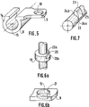
- FIG. 5 is a perspective view of the plate 8 according to another embodiment of the invention.
- This plate 8 comprises a head 9, comprising a hole 10 whose diameter corresponds to that of the plate thread.
- the plate further comprises, disposed substantially perpendicular to the head, a groove 14.
- This groove 14 includes a split bore 15, the opening of which corresponds to the diameter of the rod.
- the embodiment shown is that in which the split bore has the shape of an ⁇ (omega), which is "turned over" in the figure.
- FIG. 6a is an enlarged view of a crown 19, when the latter is present, of the screw 1.
- This crown 19 has a flat 20, consisting of a face 20a parallel to the axis of the screw and of a face 20b transverse or perpendicular to the axis of the screw. This flat engages in correspondence in the head of the plate in order to prevent any rotation of the plate around the screw.
- the crown is optional when the tightening means 4 has a profile of 6 flat sides, since in the latter case the clamping means has the flat face 20a.
- FIG. 6b is an enlarged view of the head of the plate which adapts to the crown described in FIG. 6a.
- the head 9 has, in the lower part of the hole 10, also a flat 20 whose flat part corresponds to the face 20a on the flat 21 of the screw 1, or corresponds to one of the flanges of the clamping means 4 when the latter is that shown in Figure la.
- FIG 7 is a perspective view of a fastening means according to an embodiment of the present invention.
- This fixing means is placed on the rod 22 and is called in the following key.
- This key 23 has an internal diameter substantially equal to the diameter of the rod and covers the latter over substantially a quarter of its periphery. An overlap greater than half leading to a slight pinching effect of the key, for example in the case where the key is symmetrical, may however be sought in certain cases.
- the key 23 can rotate around the rod 22, by means of a material which exerts a rotational force by resting on the faces 24a and 24b (hidden in the figure).
- the key is eccentric and has a face 25 having a convex profile and which extends from the face 24a and the face 24b (not shown in the figure).
- This key causes, during its rotation in the bore 15 of the plate, the spacing of the latter and the stress forces block the rod, key and plate in a final position.
- This rotation of the key in the bore is made possible by the convex face 25 of the key which only opposes low friction during rotation. the acute angle formed by the faces 25 and 24b prevents any subsequent rotation of the key.
- Figure 8 is a view of a cross plate according to the present invention.
- This plate 26 has at each of its ends two holes, respectively 26a and 26b, of generally oval shape.
- This plate has a general shape and is made of a material that allows its adaptation to the anatomy of the vertebra.
- Figure 9 is a perspective view of the osteosynthesis system according to the present invention, as mounted on a vertebra and at the stage where the grub screw must be put in place to effect the securing of the system.
- the dotted lines indicate the part of the pedicle screw hidden by the plate or in the vertebral bone.
- the intraosseous pedicle thread is from a length of about 35 to about 45 mm, the diameter varies from about 3.5 to about 5.5 mm for the most cylindrical part. inside the bone and from about 4.5 to about 6.5 mm for the conical part close to the surface of the bone, when the pedicle screw has the profile as described in Figure 1.
- the platinum thread extra-osseous is about 20 mm long, sometimes longer to benefit from a more pronounced lag screw effect, and the diameter varies between about 3.5 and about 5.5 mm.
- the clamping means 4 the flat-sided element represents approximately 5 mm of the length of the plate thread.
- the overall dimensions thereof are, for example: height of approximately 10 mm, width of approximately 10 mm, length of approximately 15 mm.
- the internal diameter thereof is approximately 3 mm, or approximately the diameter of the rod.
- the bore has the shape of an omega, the opening is substantially identical to the diameter of the rod.
- the hole through the head engaging the plate thread is located about 5 mm from the edge of the plate, while the bore is placed about 3.5 mm from the edge of the plate and is made until about half the thickness of the plate.
- the thread in the bore has a diameter of approximately 4 mm and is made from the surface of the plate until the bore is reached.
- the locking screw thus has a thickness of approximately 4 mm.
- the rod has a diameter of about 3 mm and a length between 100 and 400 mm.
- the thickness of the clamping nut is around 4 mm, the lateral grooves having a depth of about 1 mm.
- the dimensions of the transverse plate are standard; for example, the length is between approximately 65 and approximately 75 mm, the width is approximately 8 mm, and the largest dimension of the oval holes is between approximately 25 and approximately 30 mm, the smallest dimension is about 4 mm and the holes are located about 3 mm from the edge of the cross plate.
- the present spinal osteosynthesis system is implemented using ancillary equipment which includes: distraction and compression forceps, rod holder, reduction tubes, screwdriver.
- FIG. 10 illustrates a characteristic element of this material, the reduction tube 27.
- the latter has a distal end 28 which fits on the free end of the plate thread of the screw, possibly on the nut. This distal end has an internal thread 29 which corresponds to the platinum thread.
- a cleaning hole 30 is also provided laterally.
- this tube allows the action of reducing clamps, the jaw of which consists of a concave part which comes to adapt to the reduction tube.
- These reduction clamps are of two types, some allowing compression by their tightening, others allowing distraction.
- the compression clamps can also be adapted on the two screws of the same vertebra and be used for derotation.
- the key-holder pliers have a distal part, the ends of the branches of which have hooks enabling stress to be exerted on the key. Any conventional ancillary equipment can also be used.
- the present osteosynthesis system can be made of any biocompatible material conventionally used in the art of prostheses, orthoses, osteosyntheses and others.
- a material having the required mechanical and biocompatibility qualities non-limiting mention may be made of titanium alloys.
- the material constituting the present osteosysthesis system is an alloy based on titanium, advantageously TA6V.
- the special lag screws that is to say with a longer platinum thread, are placed on the listhesic vertebra. At first, the surgeon distracts the overlying and underlying vertebrae. It is then possible to exert a traction in the axis of the vertebra concerned, either by tightening the nut on the plate after fitting the rod, or using a reducing tube provided with a thread corresponding to that of the platinum thread of the pedicle screw, and subsequent connection of the assembly.
- the pedicle screws are placed on the strategic vertebrae such as L5, the corresponding plates are put in place as well as any transverse plates, on each stage, the assembly is locked using a nut.
- the reduction tubes are placed on each screw and the pliers are then used.
- the surgeon exerts a proximal action of the distraction forceps and there is creation of the intervertebral gap.
- it exerts an action of the compression clamps in transverse position allowing manual derotation.
- it exerts an action of the compression clamps on the distal part of the tubes, thus ensuring lordosis.
- the clamps are then "clamped", the reduction is maintained as well, and the fixing rods can be shaped and placed in the grooves in U (respectively in ⁇ (omega)).
- the grub screws (respectively the keys) are placed on each floor, and locked.
Abstract
Description
La présente invention a pour objet un nouveau système d'ostéosynthèse rachidienne qui est polyvalent, simplifié, et rend possible une action déterminante du matériel ancillaire. La présente invention se rapporte aussi à la technique de mise en place dudit système d'ostéosynthèse.The present invention relates to a new spinal osteosynthesis system which is versatile, simplified, and makes possible a decisive action of the ancillary material. The present invention also relates to the technique for installing said osteosynthesis system.
L'ostéosynthèse du rachis dorsal, lombaire et sacré existe depuis longtemps. On fait appel à cette technique dans plusieurs indications thérapeutiques: traumatologie; rachis dégénératif, malformatif, tumoral; scoliose primitive ou secondaire; instabilité rachidienne; et autres.Osteosynthesis of the dorsal, lumbar and sacral spine has been around for a long time. This technique is used in several therapeutic indications: trauma; degenerative, malformative, tumor spine; primary or secondary scoliosis; spinal instability; and others.
Les cas pathologiques qui nécessitent donc l'ostéosynthèse sont nombreux. Dans un premier temps, on considère les déviations qui sont des anomalies particulièrement fréquentes: accentuation de la cyphose dorsale, de la lordose lombaire et surtout de la scoliose, ou déviation latérale du rachis. Les cas graves de scolioses osseuses ou structurelles, qui s'accompagnent d'une rotation des vertèbres autour de leur axe vertical sont d'origines diverses. Ces scolioses peuvent être congénitale, endocrinienne, neurologique (poliomyélite) ou musculaire (myopathie). Parfois, il n'existe pas de cause évidente, on parle de scoliose essentielle (de l'adolescent). Dans un second temps, on considère les déviations dues à des traumatismes du rachis, très souvent à la suite d'un accident de la circulation. Les fractures du rachis sans lésion médullaire (ou de la moelle épinière) requièrent, dans les cas graves, une immobilisation du rachis par ostéosynthèse. Dans le cas de fractures du rachis avec lésion médullaire, l'immobilisation par ostéosynthèse se révèle utile, particulièrement dans le cas où il y a seulement contusion ou compression médullaire, c'est-à-dire dans les cas où il existe une possibilité de régression. Enfin, on considère que le recours à l'ostéosynthèse est efficace aussi dans le cas de tumeurs malignes. L'ostéosynthèse est aussi utilisée dans le cas d'ostéoporose ou d'épiphysite vertébrale, qui se traduisent sur le plan du rachis par l'apparition de cyphose accompagnant des déformations vertébrales (vertèbres cunéiformes, trapézoïdales). On a aussi recours à l'ostéosynthèse dans les cas graves d'arthrose. Il est donc évident qu'il existe un besoin en matériel d'ostéosynthèse rachidienne, car les cas pathologiques qui nécessitent un tel matériel sont nombreux.The pathological cases which therefore require osteosynthesis are numerous. First, we consider the deviations which are particularly frequent anomalies: accentuation of the dorsal kyphosis, lumbar lordosis and especially scoliosis, or lateral deviation of the spine. The serious cases of osseous or structural scoliosis, which are accompanied by a rotation of the vertebrae around their vertical axis are of various origins. These scoliosis can be congenital, endocrine, neurological (poliomyelitis) or muscular (myopathy). Sometimes there is no obvious cause, we talk about essential (adolescent) scoliosis. In a second step, we consider the deviations due to trauma to the spine, very often following a traffic accident. Fractures of the spine without spinal cord injury (or of the spinal cord) require, in severe cases, immobilization of the spine by osteosynthesis. In the case of spinal fractures with spinal cord injury, immobilization by osteosynthesis is useful, particularly in the case where there is only contusion or spinal compression, that is to say in cases where there is a possibility of regression. Finally, we consider that the use of osteosynthesis is also effective in the case of malignant tumors. Osteosynthesis is also used in the case of osteoporosis or vertebral epiphysitis, which results in the spine by the appearance of kyphosis accompanying vertebral deformations (cuneiform, trapezoidal vertebrae). Osteosynthesis is also used in severe cases of osteoarthritis. It is therefore obvious that there is a need for spinal osteosynthesis material, because the pathological cases which require such material are numerous.
De nombreux systèmes d'ostéosynthèse ont été proposés jusqu'à présent. Le matériel de Harrington, un des plus anciens, se compose de crochets sus- et sous-lamaires et de tiges. L'appui vertébral se fait au niveau des deux extrémités et la réduction ne peut se faire qu'en distraction. Ce matériel ancien présente des inconvénients notables: faibles possibilités de manoeuvres, faible tenue aux extrémités et un encombrement important. Le matériel de Cotrel a marqué une évolution notable et il permet une fixation plus courte, plus stable, et des manoeuvres de réduction plus complexes. Ce matériel comprend des crochets sous-pédiculaires d'un type nouveau, des vis pédiculaires, éventuellement dites "vis tulipe", des tiges ayant une surface diamantée, et un dispositif de traction/renforcement de traction transversale. Néanmoins, ce matériel, bien qu'étant une évolution sensible par rapport au précédent, présente toujours des inconvénients majeurs. Ainsi, outre la complexité du matériel de Cotrel, les manoeuvres de réduction sur ce matériel s'effectuent par l'intermédiaire des tiges préalablement moulées sur les points d'ancrage, crochet ou vis. Ces manoeuvres peuvent conduire à la rupture des points d'appui, due à une sollicitation de l'os trop importante, ou peuvent avoir comme résultat des réductions imparfaites, par excès ou par défaut. D'autres systèmes ont aussi été développés, et on peut citer le système de plaques vissées, dont le précurseur est le système de Roy-Camille. Celui-ci repose sur le même principe de réduction sur les points d'ancrage à partir de plaques déjà formées et conduit donc aux inconvénients précités pour le système Cotrel. Ces systèmes, plus ou moins anciens, montrent parfois des points de faiblesse et des ruptures de matériels, probablement en rapport avec les excès de contraintes mécaniques. Le système Wiltse comprend une vis pédiculaire, un étrier chevauchant cette vis et recevant dans un premier temps une matrice en aluminium malléable qui est ensuite reproduite sous forme d'une tige s'adaptant au profil dessiné par les positions des diverses vis sur le rachis, un système de fixation par écrou qui solidarise vis et tige avant l'action mécanique de réduction exercée par le chirurgien. Ce système présente les inconvénients mentionnés précédemment pour le système de Cotrel, dont il reprend par ailleurs le principe.Many osteosynthesis systems have been proposed so far. Harrington's material, one of the oldest, consists of over- and under-lamar hooks and rods. Vertebral support is done at both ends and reduction can only be done as a distraction. This old equipment has significant drawbacks: low possibilities of maneuvers, low resistance at the ends and a large size. The Cotrel material has marked a notable evolution and it allows a shorter, more stable fixation and more complex reduction maneuvers. This equipment includes sub-pedicle hooks of a new type, pedicle screws, possibly called "tulip screws", rods having a diamond surface, and a transverse traction / reinforcement device. However, this material, although being a significant development compared to the previous one, still has major drawbacks. Thus, in addition to the complexity of the Cotrel material, the reduction maneuvers on this material are carried out by means of rods previously molded on the anchor points, hook or screw. These maneuvers can lead to rupture of the support points, due to excessive stress on the bone, or can result in imperfect reductions, by excess or by default. Other systems have also been developed, and one can cite the screw plate system, the precursor of which is the Roy-Camille. This is based on the same principle of reduction on the anchor points from already formed plates and therefore leads to the aforementioned drawbacks for the Cotrel system. These systems, more or less old, sometimes show points of weakness and ruptures of equipment, probably related to excessive mechanical stresses. The Wiltse system includes a pedicle screw, a stirrup overlapping this screw and initially receiving a malleable aluminum matrix which is then reproduced in the form of a rod adapting to the profile drawn by the positions of the various screws on the spine, a fixing system using a nut which secures the screw and rod before the mechanical reduction action exerted by the surgeon. This system has the drawbacks mentioned above for the Cotrel system, the principle of which it also incorporates.
En fait, ces systèmes selon l'art antérieur présentent de nombreux problèmes. Certains matériels doivent être posés selon le plan sagittal; ceci pose évidemment le problème de l'encombrement stérique et des difficultés que rencontre le chirurgien pour accéder à la zone opératoire. Mais surtout, les matériels classiques présentent des inconvénients dus à la méthode jusqu'à présent employée pour poser ceux-ci. En effet, la séquence opératoire utilisée jusqu'à maintenant est la suivante: fixation des vis, éventuellement fixation de manière solidaire des plaques transversales, fixation de la tige (éventuellement préformée grâce à une matrice en alliage malléable permettant de reproduire le positionnement des vis selon la pathologie) solidairement sur lesdites vis, puis action mécanique à l'aide d'un matériel ancillaire. Cette séquence présente trois inconvénients majeurs. Tout d'abord, la tige qui est initialement posée se déforme et la forme finale qu'elle doit avoir n'est pas toujours atteignable, les vertèbres restant en hypo- ou hyper-réduction. Les contraintes mécaniques sont alors élevées et il est parfois nécessaire de changer la tige en cours d'opération et de la remplacer par une tige ayant une forme intermédiaire. Ceci peut être critique dans certains cas opératoires délicats comme, par exemple, ceux faisant intervenir un appui iliaque. Le second problème que présentent ces systèmes d'ostéosynthèse selon l'art antérieur est que l'action mécanique exercée par le chirurgien est la somme de l'action mécanique sur le système osseux et de l'action sur le système d'ostéosynthèse lui-même. Ainsi, le chirurgien n'est pas toujours à même d'apprécier les contraintes qu'il exerce sur les vertèbres; chez les sujets âgées, la fragilité des vertèbres peut alors conduire à un arrachement des points d'ancrage, ce qui résulte finalement en un ancrage sur la vertèbre suivante, augmentant la longueur du système d'ostéosynthèse et, par là-même, les gênes qu'il occasionne chez le patient. Enfin, la réduction du rachis est basée sur la combinaison d'action mécanique selon deux degrés de liberté. Le praticien doit, dans certains cas, exercer des actions de rotation-dérotation, tandis que, dans d'autres cas, il doit exercer des actions de compression-distraction, voire aussi des actions de tire-fond. Aucun système actuel ne permet d'effectuer ces actions mécaniques indépendantes de façon satisfaisante.In fact, these systems according to the prior art present numerous problems. Certain materials must be placed according to the sagittal plan; this obviously poses the problem of steric hindrance and the difficulties encountered by the surgeon in accessing the operating area. But above all, conventional materials have drawbacks due to the method hitherto used to lay them. In fact, the operating sequence used up to now is as follows: fixing of the screws, optionally fixing in solidarity with the transverse plates, fixing of the rod (possibly preformed by means of a malleable alloy matrix making it possible to reproduce the positioning of the screws according to pathology) solidly on said screws, then mechanical action using ancillary equipment. This sequence has three major drawbacks. First of all, the stem which is initially laid deforms and the final shape which it must have is not always attainable, the vertebrae remaining in hypo- or hyper-reduction. The mechanical stresses are then high and it is sometimes necessary to change the rod during operation and to replace it with a rod having an intermediate shape. This can be critical in certain delicate operating cases such as, for example, those involving iliac support. The second problem presented by these osteosynthesis systems according to the prior art is that the mechanical action exerted by the surgeon is the sum of the mechanical action on the bone system and the action on the osteosynthesis system itself. even. Thus, the surgeon is not always able to appreciate the stresses he exerts on the vertebrae; in the elderly, the fragility of the vertebrae can then lead to tearing of the anchor points, which ultimately results in anchoring on the next vertebra, increasing the length of the osteosynthesis system and, thereby, the genes that it causes in the patient. Finally, the reduction of the spine is based on the combination of mechanical action according to two degrees of freedom. The practitioner must, in certain cases, exert rotation-derotation actions, while, in other cases, he must exert compression-distraction actions, even also lag screw actions. No current system allows these independent mechanical actions to be carried out satisfactorily.
Il existe donc un besoin d'un système d'ostéosynthèse rachidienne qui permet le travail dans le plan frontal, des actions mécaniques sur le matériel et les os séparées, une fiabilité conduisant immédiatement et sûrement à la forme de tige requise, et qui permette des actions de rotation-dérotation, de compression-distraction, et de tire-fond aisées. Cet objet, ainsi que d'autres, est atteint par la présente invention.There is therefore a need for a spinal osteosynthesis system which allows work in the frontal plane, mechanical actions on the material and the separate bones, reliability immediately and surely leading to the required rod shape, and which allows easy rotation-derotation, compression-distraction, and lag screws. This and other objects are achieved by the present invention.
Ainsi, la présente invention fournit un système d'ostéosynthèse rachidienne comprenant:
- une vis pédiculaire munie de deux filetages, le premier filetage, le filetage pédiculaire, étant introduit dans le pédicule vertébral et le second filetage, le filetage de platine, étant destiné à recevoir la platine;
- une tige;
- au moins une platine constituée d'au moins une tête perforée d'un trou dont le diamètre est sensiblement égal à celui du filetage de platine de la vis pédiculaire et au moins une gorge dont l'axe est sensiblement perpendiculaire à l'axe de la tête;
- ladite gorge comprenant un alésage fendu dont l'espace de l'ouverture correspond au moins au diamètre de la tige;
- un moyen de fixation de la platine sur la vis destiné à solidariser ladite platine au niveau de la tête sur ladite vis pédiculaire avant action mécanique de réduction;
- lesdits moyen de fixation et filetage de platine étant tels que le moyen de fixation engagé à blocage laisse libre une partie du filetage de platine;
- un moyen de fixation de la tige dans la gorge destiné à solidariser ladite tige dans ladite gorge de ladite platine après action mécanique de réduction.
- a pedicle screw provided with two threads, the first thread, the pedicle thread, being introduced into the vertebral pedicle and the second thread, the platinum thread, being intended to receive the platinum;
- a rod;
- at least one plate consisting of at least one head perforated with a hole whose diameter is substantially equal to that of the plate thread of the pedicle screw and at least one groove whose axis is substantially perpendicular to the axis of the head;
- said groove comprising a split bore whose space of the opening corresponds at least to the diameter of the rod;
- means for fixing the plate on the screw intended to secure said plate at head level on said pedicle screw before mechanical reduction action;
- said fixing means and platinum thread being such that the fixing means engaged in locking leaves part of the platinum thread free;
- means for fixing the rod in the groove intended to secure said rod in said groove of said plate after mechanical reduction action.
Le nouveau système d'ostéosynthèse rachidienne selon la présente invention permet au chirurgien d'intervenir sur le rachis de façon plus simple, plus efficace et plus sûre. En fait, le présent système d'ostéosynthèse rachidienne permet la séquence opératoire suivante:
- a) fixation des vis pédiculaires;
- b) fixation de la platine, comprenant une tête et une gorge, solidairement sur la vis pédiculaire par introduction sur la vis pédiculaire de la tête perforée d'un trou d'un diamètre sensiblement égal à celui du filetage de platine de la vis pédiculaire, puis blocage par un écrou sur le filetage de platine, ledit écrou une fois en position bloquée laissant une partie du filetage de platine libre;
- c) action mécanique sur les vis pédiculaires à l'aide d'un matériel ancillaire constitué d'un tube de réduction et de pinces pour distraction, contraction et (dé)rotation dont le mors à l'extrémité distale a la forme générale d'un croissant de lune s'adaptant au tube précité; subséquemment, blocage en cette position par des "clamps";
- d) à l'issue de l'action mécanique, prise de l'empreinte des vis et platines et fabrication d'une tige correspondante;
- e) mise en place de ladite tige préformée sur l'ensemble des vis, ladite tige étant insérée dans l'alésage fendu de ladite gorge et un moyen de fixation de la tige dans la gorge est alors mis en oeuvre pour obtenir le blocage de l'ensemble qui forme le système d'ostéosynthèse rachidienne en position définitive;
- f) retrait du matériel ancillaire et terminaison de l'intervention chirurgicale.
- a) fixing the pedicle screws;
- b) fixing of the plate, comprising a head and a groove, integrally on the pedicle screw by introduction on the pedicle screw of the perforated head with a hole of a diameter substantially equal to that of the thread of the plate of the pedicle screw, then blocking by a nut on the plate thread, said nut once in the locked position leaving part of the plate thread free;
- c) mechanical action on the pedicle screws using ancillary equipment consisting of a reduction tube and clamps for distraction, contraction and (de) rotation whose jaw at the distal end has the general shape of a crescent moon adapting to the aforementioned tube; subsequently, blocking in this position by "clamps";
- d) at the end of the mechanical action, taking the impression of the screws and plates and manufacturing a corresponding rod;
- e) placing of said preformed rod on all of the screws, said rod being inserted in the split bore of said groove and a means for fixing the rod in the groove is then used to obtain the blocking of the 'assembly which forms the spinal osteosynthesis system in the final position;
- f) removal of the ancillary material and termination of the surgical intervention.
Cette séquence opératoire, rendue possible grâce au nouveau système d'ostéosynthèse rachidienne selon la présente invention permet donc une action mécanique uniquement sur les os. Le chirurgien, ne prenant en compte que les contraintes du système osseux, peut donc éviter une action mécanique trop importante qui pouvait conduire, dans certains cas pathologiques, avec des patients âgés par exemple et avec le matériel selon l'art antérieur, à des bris de matériel, le plus souvent d'os ainsi qu'à des arrachements de points d'ancrage, ce qui obligeait à poser le matériel sur la vertèbre suivante. De plus, la tige préformée est la réplique de la tige en position finale, alors que selon l'art antérieur, on exerçait une action sur le matériel complet, c'est-à-dire avec la tige, et à l'issue de l'action mécanique de réduction, la tige pouvait se révéler inadaptée car trop courte ou trop longue, ou subissant des contraintes mécaniques trop importantes, et on pouvait alors soit laisser le patient avec une hypo- ou une hyper-réduction, soit on devait recommencer en partant d'une position intermédiaire, ce qui nécessitait un temps d'intervention et d'anesthésie plus long. Enfin, le matériel selon l'invention est parfaitement adapté à une intervention dans le plan frontal; ce qui permet une plus grande facilité de mouvement; cependant, il est possible de poser le nouveau système d'ostéosynthèse rachidienne selon la présente invention dans le plan sagittal.This operating sequence, made possible by the new spinal osteosynthesis system according to the present invention therefore allows mechanical action only on the bones. The surgeon, taking into account only the constraints of the bone system, can therefore avoid excessive mechanical action which could lead, in certain pathological cases, with elderly patients for example and with the material according to the prior art, to breakage. of material, most often of bone as well as tearing of anchor points, which forced to place the material on the next vertebra. In addition, the preformed rod is the replica of the rod in the final position, whereas according to the prior art, an action was exerted on the complete material, that is to say with the rod, and at the end of mechanical reduction action, the rod could turn out to be unsuitable because it was too short or too long, or undergoing too great mechanical stress, and we could then either leave the patient with hypo- or hyper-reduction, or we had to start again starting from an intermediate position, which required a longer intervention and anesthesia time. Finally, the equipment according to the invention is perfectly suited to intervention in the frontal plane; which allows greater ease of movement; however, it is possible to place the new spinal osteosynthesis system according to the present invention in the sagittal plane.
En fait, les inconvénients selon l'art antérieur dérivent du fait que la séquence opératoire utilisée était, avec la nomenclature ci-dessus, et pour un système du type Cotrel, Wiltse, ou autres: (a), (b), (d), (e), (c), (f). La séquence selon l'art antérieur est en fait:
- a) fixation des vis pédiculaires;
- b) fixation de la platine, comprenant une tête et une gorge, solidairement sur la vis pédiculaire par introduction sur la vis pédiculaire de la tête perforée d'un trou d'un diamètre sensiblement égal à celui du filetage de platine de la vis pédiculaire, puis blocage par un écrou sur le filetage de platine, ledit écrou une fois en position bloquée laissant une partie du filetage de platine libre;
- d) prise de l'empreinte des vis et platines et fabrication d'une tige préformée correspondante ayant la forme de la pathologie;
- e) mise en place de ladite tige préformée sur l'ensemble des vis, ladite tige étant insérée dans l'alésage fendu de ladite gorge et un moyen de fixation de la tige dans la gorge est alors mis en oeuvre pour obtenir le blocage de l'ensemble qui forme le système d'ostéosynthèse rachidienne, ce dernier constituant alors un système mécanique hyperstatique;
- c) action mécanique sur ce système mécanique, par l'intermédiaire des vis pédiculaires, à l'aide d'un matériel ancillaire constitué d'un tube de réduction et de pinces pour distraction, contraction et dérotation dont le mors à l'extrémité distale a la forme générale d'un croissant de lune s'adaptant au tube précité;
- f) retrait du matériel ancillaire et terminaison de l'intervention chirurgicale.
Grâce au présent système d'ostéosynthèse rachidienne, la séquence selon l'invention est permise.In fact, the drawbacks according to the prior art derive from the fact that the operating sequence used was, with the above nomenclature, and for a system of the Cotrel, Wiltse type, or others: (a), (b), (d ), (e), (c), (f). The sequence according to the prior art is in fact:
- a) fixing the pedicle screws;
- b) fixing of the plate, comprising a head and a groove, integrally on the pedicle screw by introduction on the pedicle screw of the perforated head with a hole of a diameter substantially equal to that of the plate thread of the pedicle screw, then blocking by a nut on the plate thread, said nut once in the locked position leaving part of the plate thread free;
- d) taking the impression of the screws and plates and manufacturing a corresponding preformed rod having the shape of the pathology;
- e) placing of said preformed rod on all of the screws, said rod being inserted in the split bore of said groove and a means for fixing the rod in the groove is then used to obtain the blocking of the 'assembly which forms the spinal osteosynthesis system, the latter then constituting a hyperstatic mechanical system;
- c) mechanical action on this mechanical system, by means of pedicle screws, using ancillary equipment consisting of a reduction tube and pliers for distraction, contraction and derotation, the jaw of which at the distal end has the general shape of a crescent moon adapting to the aforementioned tube;
- f) removal of the ancillary material and termination of the surgical intervention.
Thanks to the present spinal osteosynthesis system, the sequence according to the invention is permitted.
Il est possible de fournir de multiples variantes du présent système d'ostéosynthèse rachidienne, toutes aisément accessibles à l'homme de l'art et qui permettent une adaptation à chaque cas pathologique.It is possible to provide multiple variants of the present spinal osteosynthesis system, all easily accessible to those skilled in the art and which allow adaptation to each pathological case.
Dans la présente vis pédiculaire, le filetage de platine est à pas faible tandis que le filetage pédiculaire présente un pas large.In the present pedicle screw, the platinum thread has a small pitch while the pedicle thread has a wide pitch.
La vis pédiculaire est munie d'un moyen de serrage approprié qui permet de visser cette vis pédiculaire dans l'os pédiculaire. De préférence, ce moyen de serrage est situé entre les deux filetages.The pedicle screw is provided with a suitable clamping means which makes it possible to screw this pedicle screw into the bone pedicular. Preferably, this clamping means is located between the two threads.
Selon un mode de réalisation, ce moyen de serrage est un écrou hexagonal situé entre le filetage de platine et le filetage pédiculaire. Avantageusement, au moins un des pans de l'écrou hexagonal correspond avec un méplat présent sur la tête de la platine.According to one embodiment, this tightening means is a hexagonal nut located between the platinum thread and the pedicle thread. Advantageously, at least one of the sections of the hexagonal nut corresponds with a flat present on the head of the plate.
L'alésage fendu peut avoir toute forme possible qui permette à la tige d'être introduite dans la gorge et fixée solidairement dans celle-ci.
Selon un mode de réalisation, l'alésage fendu a la forme d'un U tandis que selon une autre variante, ledit alésage a la forme d'un Ω (oméga).The split bore may have any possible shape which allows the rod to be introduced into the groove and fixed integrally therein.
According to one embodiment, the split bore has the shape of a U while according to another variant, said bore has the shape of an Ω (omega).
Tout moyen de fixation de la platine sur la vis pédiculaire est approprié; néanmoins on préfére un écrou.Any means of fixing the plate to the pedicle screw is suitable; however we prefer a nut.
Tout système de fixation de la tige dans la gorge de la platine est approprié, selon les formes respectives de la gorge et de la tige. Il est possible, par exemple, d'utiliser une vis dont le diamètre est croissant et qui est introduite dans l'espace laissé libre entre la tige et l'alésage fendu. Lors du vissage de la vis, cette dernière, du fait de son diamètre croissant, exerce alors une contrainte mécanique qui permet de bloquer tige et gorge de la platine; ce type de fixation est par ailleurs déjà utilisé, notamment au cours de l'opération de ligamentoplastie de remplacement du ligament croisé antérieur. Tout autre système est adapté, notamment le système de bagues enfilées sur la tige, ou encore de clavette.Any system for fixing the rod in the groove of the plate is appropriate, depending on the respective shapes of the groove and the rod. It is possible, for example, to use a screw whose diameter is increasing and which is introduced into the space left free between the rod and the split bore. When the screw is screwed, the latter, due to its increasing diameter, then exerts a mechanical stress which makes it possible to block the rod and groove of the plate; this type of fixation is also already used, in particular during the ligament replacement surgery for replacing the anterior cruciate ligament. Any other system is suitable, in particular the system of rings threaded on the rod, or even of the key.
Selon un mode de réalisation, avantageusement lorsque l'alésage fendu a la forme d'un Ω (oméga), le moyen de fixation de la tige dans la gorge est une clavette excentrique dont le diamètre interne est substantiellement identique à celui de la tige et dont le diamètre externe est tel qu'une action mécanique de contrainte est exercée sur la platine lors de la rotation ou translation de ladite clavette.According to one embodiment, advantageously when the split bore has the shape of an Ω (omega), the means of fixing the rod in the groove is an eccentric key whose internal diameter is substantially identical to that of the rod and whose external diameter is such that a mechanical stressing action is exerted on the plate during the rotation or translation of said key.
Selon un autre mode de réalisation, lorsque l'alésage a la forme d'un U, le moyen de fixation de la tige dans la gorge est une vis s'engageant dans un filetage ménagé dans l'alésage de la gorge, sensiblement perpendiculairement à cette dernière et sensiblement parallèlement à la vis pédiculaire. De préférence, la vis de fixation est une vis sans tête.According to another embodiment, when the bore has the shape of a U, the means of fixing the rod in the groove is a screw engaging in a thread formed in the bore of the groove, substantially perpendicular to the latter and substantially parallel to the pedicle screw. Preferably, the fixing screw is a headless screw.
La vis pédiculaire peut par ailleurs comporter d'autres éléments mécaniques ayant des fonctions définies. Ainsi, la vis comporte avantageusement un moyen de limiter sa course afin que seule la longueur nécessaire de la vis soit placée dans le pédicule de la vertèbre, et que la zone médullaire ne subisse ni lésion, ni compression.
Avantageusement, la vis comporte une couronne externe entre les filetages afin de placer la vis pédiculaire en butée sur le rachis.The pedicle screw may also include other mechanical elements having defined functions. Thus, the screw advantageously comprises a means of limiting its stroke so that only the necessary length of the screw is placed in the pedicle of the vertebra, and so that the medullary zone does not suffer any injury or compression.
Advantageously, the screw has an external crown between the threads in order to place the pedicle screw in abutment on the spine.
Selon un mode de réalisation de la présente invention, la vis pédiculaire est de section décroissante dans sa partie pédiculaire. Avantageusement, le filetage pédiculaire possède un profil à fond plat.According to an embodiment of the present invention, the pedicle screw is of decreasing section in its pedicle part. Advantageously, the pedicle thread has a flat bottom profile.
Tout écrou est approprié pour fixer la platine sur la vis pédiculaire; cependant on donne la préférence à un écrou portant des rainures, destinées à recevoir et à guider le moyen de serrage.Any nut is suitable for fixing the plate to the pedicle screw; however, preference is given to a nut carrying grooves, intended to receive and guide the clamping means.
On cherchera aussi à éviter la rotation de la platine sur la vis pendant l'étape de serrage de l'écrou qui bloque la platine sur la vis. Tout système mécanique à cette fin peut être utilisé, par exemple une canelure taillée dans le filetage de platine, et qui correspond à une saillie située sur la périphérie du trou de la tête de la platine.
Selon un mode de réalisation, la tête de la platine comporte un méplat et la vis pédiculaire comporte sur la couronne externe entre les deux filetages un méplat, lesdits méplats étant correspondants et s'engageant afin d'empêcher toute rotation de la platine sur la vis.
Selon un autre mode de réalisation, la tête de la platine comporte un méplat et la vis pédiculaire comporte un écrou hexagonal situé entre le filetage de platine et le filetage pédiculaire, ledit méplat et au moins un pan de l'écrou héxagonal étant correspondants et s'engageant afin d'empêcher toute rotation de la platine sur la vis.
Selon un autre mode de réalisation, la couronne externe située entre les deux filetages de la vis pédiculaire est une couronne dentée s'engageant dans une couronne dentée correspondante sur la platine, afin d'empêcher toute rotation de la platine sur la vis.We will also try to avoid the rotation of the plate on the screw during the step of tightening the nut which blocks the plate on the screw. Any mechanical system for this purpose can be used, for example a groove cut in the thread of the plate, and which corresponds to a projection located on the periphery of the hole in the head of the plate.
According to one embodiment, the head of the plate has a flat and the pedicle screw comprises on the external crown between the two threads a flat, said flat being corresponding and engaging in order to prevent any rotation of the plate on the screw .
According to another embodiment, the head of the plate comprises a flat and the pedicle screw comprises a hexagonal nut situated between the plate thread and the pedicle thread, said flat and at least one section of the hexagonal nut being corresponding and s engaging to prevent any rotation of the plate on the screw.
According to another embodiment, the external crown situated between the two threads of the pedicle screw is a toothed crown engaging in a corresponding toothed crown on the plate, in order to prevent any rotation of the plate on the screw.
Le système d'ostéosynthèse selon la présente invention peut être posé sur le rachis sur un côté seulement, ou sur les deux côtés. Dans ce dernier cas, le système selon la présente invention intègre un élément mécanique approprié afin de relier, si on le souhaite, les deux vis posées sur une même vertèbre.
De préférence, cet élément de liaison est une plaque transversale s'étendant entre deux vis pédiculaires sur une même vertèbre, fixée solidairement sur celles-ci avec les deux platines correspondantes et les deux écrous correspondants, avant action mécanique de réduction. Les trous aux extrémités de la plaque transversale sont avantageusement ovalaires, de sorte à n'employer qu'une plaque transversale pouvant s'adapter à diverses conformations osseuses de vertèbres différentes. La plaque peut être posée après réduction pour réaliser un montage dit "montage en cadre".The osteosynthesis system according to the present invention can be placed on the spine on one side only, or on both sides. In the latter case, the system according to the present invention incorporates an appropriate mechanical element in order to connect, if desired, the two screws placed on the same vertebra.
Preferably, this connecting element is a transverse plate extending between two pedicle screws on the same vertebra, fixed integrally thereon with the two corresponding plates and the two corresponding nuts, before mechanical reduction action. The holes at the ends of the transverse plate are advantageously oval, so as to use only a transverse plate capable of adapting to various bone conformations of different vertebrae. The plate can be placed after reduction to make a mounting called "frame mounting".
La platine possède au moins une gorge, mais il n'y a aucune contre-indication à ce que la platine soit munie de plus d'une gorge. Selon un mode de réalisation de la présente invention, la platine possède deux gorges. Cette platine à deux gorges peut être utilisée, par exemple, en lieu et place des dominos, habituellement utilisés pour joindre deux tiges distinctes.The plate has at least one groove, but there is no contraindication for the plate to be provided with more than one groove. According to an embodiment of the present invention, the plate has two grooves. This plate with two grooves can be used, for example, in place of dominoes, usually used to join two separate rods.
Par ailleurs, la vis pédiculaire n'est pas limitée à porter une seule platine. Selon un mode de réalisation de la présente invention, le système d'ostéosynthèse rachidienne comprend deux platines, inférieure et supérieure. La présence de ces deux platines permet de générer deux axes de renforcement, par exemple, de substituer la plaque transversale par une tige similaire à celle utilisée longitudinalement au rachis.Furthermore, the pedicle screw is not limited to carrying a single plate. According to an embodiment of the present invention, the spinal osteosynthesis system comprises two plates, lower and upper. The presence of these two plates makes it possible to generate two axes of reinforcement, for example, to replace the transverse plate by a rod similar to that used longitudinally for the spine.
Selon ce mode de réalisation, les platines sont solidarisées toujours avec un écrou et il est souhaitable d'éviter leur rotation l'une par rapport à l'autre, de la mâme façon que précédemment, par rapport à la vis pédiculaire. Selon un mode d'exécution de cette variante de l'invention, la platine inférieure possède au moins un méplat supérieur sur la tête, la platine supérieure possède un méplat inférieur, lesdits méplats supérieur de la platine inférieure et inférieur de la platine supérieure venant en engagement. Selon un autre mode d'exécution de cette variante de l'invention, la platine inférieure possède au moins une couronne dentée supérieure sur la tête, la platine supérieure possède une couronne dentée inférieure, lesdites couronnes dentées supérieure de la platine inférieure et inférieure de la platine supérieure venant en engagement.According to this embodiment, the plates are always secured with a nut and it is desirable to avoid their rotation with respect to each other, in the same way as previously, with respect to the pedicle screw. According to one embodiment of this variant of the invention, the lower plate has at least one upper flat on the head, the upper plate has a lower flat, said upper flats of the lower plate and lower of the upper plate coming in commitment. According to another embodiment of this variant of the invention, the lower plate has at least one upper toothed crown on the head, the upper plate has a lower toothed crown, said upper toothed crowns of the lower and lower plate of the upper plate coming in engagement.
Ce nouveau système d'ostéosynthèse rachidienne est donc parfaitement adapté à une utilisation selon la nouvelle séquence opératoire chirurgicale. Ainsi, la présente invention a aussi pour objet l'utilisation du système d'osthéosynthèse rachidienne pour la réduction de rachis avec action mécanique de réduction antérieure à la fixation des tiges sur les vis pédiculaires.This new spinal osteosynthesis system is therefore perfectly suited for use according to the new surgical operating sequence. Thus, the present invention also relates to the use of the spinal osteosynthesis system for the reduction of the spine with mechanical reduction action prior to the attachment of the rods to the pedicle screws.
La présente invention est maintenant décrite plus en détail en référence aux dessins des figures suivantes:
- la figure 1a est une vue d'une vis pédiculaire selon la présente invention;
- la figure 1b est une vue en élévation de la même vis;
- la figure 2a est une vue de face de l'écrou pédiculaire;
- la figure 2b est une vue de dessus de l'écrou pédiculaire;
- la figure 3a est une vue de face d'une platine selon un premier mode de réalisation de la présente invention;
- la figure 3b est une vue de dessus de la platine représentée à la figure 3a;
- la figure 3c est une vue de la coupe identifiée par AA sur la figure 3a;
- la figure 4 est une vue de la vis sans tête de blocage de la tige dans l'alésage;
- la figure 5 est une vue en perspective de la platine selon un autre mode de réalisation de l'invention;
- la figure 6a est une vue d'une couronne sur la vis pédiculaire;
- la figure 6b représente la tête de platine s'engageant sur la couronne représentée à la figure précédente;
- la figure 7 est une vue en perspective d'un moyen de fixation selon un mode de réalisation de l'invention;
- la figure 8 est une vue de la plaque transversale selon l'invention;
- la figure 9 est une vue en perspective du système d'ostéosynthèse selon l'invention;
- la figure 10 représente un tube de réduction utilisé pour la mise en oeuvre de l'invention.
- Figure 1a is a view of a pedicle screw according to the present invention;
- Figure 1b is an elevational view of the same screw;
- Figure 2a is a front view of the pedicle nut;
- Figure 2b is a top view of the pedicle nut;
- Figure 3a is a front view of a plate according to a first embodiment of the present invention;
- Figure 3b is a top view of the plate shown in Figure 3a;
- Figure 3c is a view of the section identified by AA in Figure 3a;
- Figure 4 is a view of the grub screw locking the rod in the bore;
- Figure 5 is a perspective view of the plate according to another embodiment of the invention;
- Figure 6a is a view of a crown on the pedicle screw;
- Figure 6b shows the platinum head engaging on the crown shown in the previous figure;
- Figure 7 is a perspective view of a fastening means according to an embodiment of the invention;
- Figure 8 is a view of the transverse plate according to the invention;
- Figure 9 is a perspective view of the osteosynthesis system according to the invention;
- FIG. 10 represents a reduction tube used for the implementation of the invention.
La figure la est une représentation d'une vis pédiculaire 1 selon l'invention. Cette vis 1 comporte deux filetages, le premier filetage 2 pédiculaire à pas large étant introduit dans la partie osseuse de la vertèbre au niveau du pédicule. Le second filetage 3 de platine à pas faible est situé dans la partie extra-osseuse de la vis pédiculaire. Ce dernier filetage est destiné à recevoir, d'une part, la platine et l'écrou de blocage, éventuellement la plaque transversale, et d'autre part, le matériel ancillaire constitué des tubes et pinces définis ci-avant. De préférence, la partie intra-osseuse, c'est-à-dire la partie portant le filetage pédiculaire, est de forme globalement conique dans sa partie supérieure et globalement cylindrique dans sa partie inférieure, comme illustrée précisément sur la figure 1. Cependant, une forme cylindrique sur toute la longueur ou toute autre forme est appropriée. La vis 1 peut comporter une couronne (non représentée), dont une fonction est d'assurer la mise en butée de la vis pédiculaire sur l'os. La vis comporte un moyen de serrage 4. Celui-ci peut être une entaille au sommet du filetage de platine, de façon à créer un espace permettant d'insérer un tournevis plat, cruciforme, hexagonal. De préférence, ce moyen de serrage 4 a la forme générale d'un écrou à 6 pans plats permettant de recevoir une clé de serrage. Tout autre moyen de serrage peut être utilisé, par exemple une cavité hexagonale qui reçoit un tournevis de montage dont l'extrêmité s'adapte à la cavité hexagonale sus-citée.Figure la is a representation of a pedicle screw 1 according to the invention. This screw 1 has two threads, the
La figure 1b est une vue en élévation de la vis 1 selon la présente invention. On distingue nettement le profil à 6 pans plats du moyen de serrage 4 ainsi que le filetage 3 de platine.Figure 1b is an elevational view of the screw 1 according to the present invention. There is a clear distinction between the flat hexagon profile of the clamping means 4 and the
La figure 2a est une vue de face de l'écrou pédiculaire ou écrou de blocage 5 de la platine. Le diamètre interne et la pas de vis de l'écrou 5 correspondent aux diamètre et pas du filetage de platine 3. Cet écrou 5 possède selon le mode de réalisation représenté deux rainures latérales 6a et 6b destinées à recevoir l'instrument de serrage. Il possède aussi une couronne 7 qui se trouve au niveau de la zone de contact.Figure 2a is a front view of the pedicle nut or locking
La figure 2b est une vue selon la coupe AA donnée à la figure 2a du même écrou pédiculaire.Figure 2b is a view along section AA given in Figure 2a of the same pedicle nut.
La figure 3a est une vue de face d'une platine selon un mode de réalisation de la présente invention. Cette platine 8 comporte une tête 9 percée d'un trou 10. L'extrêmité médiane 11 de ce trou est d'un diamètre similaire à celui du filetage 3 de platine, filetage sur lequel la platine vient s'engager. La partie inférieure 12 du trou, i.e. la partie la plus proche de l'os, possède un diamètre et une profondeur suffisants pour s'adapter et venir chapeauter le moyen 4 de serrage, représenté par un profil 6 pans plats. La partie supérieure 13 du trou, i.e. la partie la plus éloignée de l'os, possède un diamètre et une profondeur suffisants pour s'adapter à l'écrou pédiculaire 5. La platine comprend en outre, disposée substantiellement perpendiculairement à la tête, une gorge 14. Cette gorge 14 comprend un alésage fendu 15, dont le diamètre correspond sensiblement au diamètre de la tige que l'alésage reçoit. Selon le mode de réalisation représenté sur la figure, l'alésage a la forme d'un U. Cet alésage possède en outre un filetage 16, disposé perpendiculairement à l'alésage et sensiblement parallèle à l'axe du trou 10, destiné à recevoir la vis sans tête de blocage 17.Figure 3a is a front view of a plate according to an embodiment of the present invention. This plate 8 comprises a
La figure 3b est une vue de dessus de la platine 8, dans laquelle on retrouve les éléments suivants: tête 9, trou 10, gorge 14, alésage 15 et filetage 16.FIG. 3b is a top view of the plate 8, in which the following elements are found:
La figure 3c est une vue de la coupe identifiée comme AA sur la figure 3a. Cette coupe est réalisée dans la gorge 14 au niveau de l'alésage 15 et réprésente plus en détail le filetage 16. Ce dernier s'étend sur toute la profondeur de l'alésage, bien que cela ne soit pas critique pour la réalisation de l'invention, qui est atteinte lorsque le filetage s'étend sur une longueur suffisante pour que l'extrêmité de la vis de blocage soit en contact serré avec la tige.Figure 3c is a view of the section identified as AA in Figure 3a. This cut is made in the
La figure 4 est une vue de la vis sans tête de blocage 17, qui s'engage dans le filetage 16 prévu dans l'alésage 15. Cette vis sans tête possède un évidement 18 ayant une forme hexagonale, type à 6 pans plats, permettant de recevoir un outil pour le serrage de la vis de blocage.Figure 4 is a view of the locking
La figure 5 est une vue en perspective de la platine 8 selon un autre mode de réalisation de l'invention. Les éléments dont seulement des variantes d'éxécution sont représentées sont numérotés de façon identique. Cette platine 8 comprend une tête 9, comportant un trou 10 dont le diamètre correspond à celui du filetage de platine. La platine comprend en outre, disposée substantiellement perpendiculairement à la tête, une gorge 14. Cette gorge 14 comprend un alésage fendu 15, dont l'ouverture correspond au diamètre de la tige. Le mode réalisation représenté est celui dans lequel l'alésage fendu possède la forme d'un Ω (oméga), qui est "retourné" sur la figure.Figure 5 is a perspective view of the plate 8 according to another embodiment of the invention. The elements of which only variants are shown are numbered identically. This plate 8 comprises a
La figure 6a est une vue agrandie d'une couronne 19, lorsque celle-ci est présente, de la vis 1. Cette couronne 19 possède un méplat 20, constitué d'une face 20a parallèle à l'axe de la vis et d'une face 20b transverse ou perpendiculaire à l'axe de la vis. Ce méplat s'engage en correspondance dans la tête de la platine afin d'empêcher toute rotation de la platine autour de la vis. En fait, la couronne est optionnelle lorsque le moyen de serrage 4 possède un profil à 6 pans plats, puisque dans ce dernier cas le moyen de serrage présente la face plane 20a.FIG. 6a is an enlarged view of a
La figure 6b est une vue agrandie de la tête de la platine qui s'adapte à la couronne décrite figure 6a. La tête 9 possède, dans la partie inférieure du trou 10, aussi un méplat 20 dont la partie plane correspond à la face 20a sur le méplat 21 de la vis 1, ou correspond à un des pans du moyen de serrage 4 lorsque ce dernier est celui représenté à la figure la.FIG. 6b is an enlarged view of the head of the plate which adapts to the crown described in FIG. 6a. The
La figure 7 est une vue en perspective d'un moyen de fixation selon un mode de réalisation de la présente invention. Ce moyen de fixation est posé sur la tige 22 et est appelé dans ce qui suit clavette. Cette clavette 23 a un diamètre intérieur sensiblement égal au diamètre de la tige et recouvre cette dernière sur substantiellement le quart de sa périphérie. Un recouvrement supérieur à la moitié conduisant à un léger effet de pincement de la clavette, par exemple dans le cas où la clavette est symétrique, peut être cependant recherché dans certains cas. La clavette 23 peut tourner autour de la tige 22, grâce à un matériel qui exerce une force de rotation en prenant appui sur les faces 24a et 24b (cachée sur la figure). La clavette est excentrique et possède une face 25 présentant un profil convexe et qui s'étend de la face 24a et de la face 24b (non représenté sur la figure). Cette clavette, dont les dimensions sont adaptées, provoque, lors de sa rotation dans l'alésage 15 de la platine, l'écartement de ce dernier et les efforts de contraintes bloquent tige, clavette et platine dans une position définitive. Cette rotation de la clavette dans l'alésage est rendue possible par la face 25 convexe de la clavette qui n'oppose qu'un frottement faible lors de la rotation. l'angle aigu formé par les faces 25 et 24b empêche toute rotation ultérieure de la clavette.Figure 7 is a perspective view of a fastening means according to an embodiment of the present invention. This fixing means is placed on the
La figure 8 est une vue d'une plaque transversale selon la présente invention. Cette plaque 26 comporte à chacune de ses extrêmités deux trous, respectivement 26a et 26b, de forme globalement ovalaire. Cette plaque a une forme générale et est réalisée dans un matériau qui permet son adaptation à l'anatomie de la vertèbre.Figure 8 is a view of a cross plate according to the present invention. This
La figure 9 est une vue en perspective du système d'ostéosynthèse selon la présente invention, tel que monté sur une vertèbre et au stade où la vis sans tête doit être mise en place pour effectuer la solidarisation du système. Les pointillés indiquent la partie de la vis pédiculaire cachée par la platine ou dans l'os vertébral.Figure 9 is a perspective view of the osteosynthesis system according to the present invention, as mounted on a vertebra and at the stage where the grub screw must be put in place to effect the securing of the system. The dotted lines indicate the part of the pedicle screw hidden by the plate or in the vertebral bone.
Les dimensions de la vis sont classiques pour les systèmes d'ostéosynthèse rachidienne classiques. Ainsi, pour la vis, le filetage pédiculaire intra-osseux est d'une longueur d'environ 35 à environ 45 mm, le diamètre varie d'environ 3,5 à environ 5,5 mm pour la partie cylindrique la plus à l'intérieur de l'os et d'environ 4,5 à environ 6,5 mm pour la partie conique proche de la surface de l'os, lorsque la vis pédiculaire présente le profil tel que décrit à la figure 1. Le filetage de platine extra-osseux est d'une longueur d'environ 20 mm, parfois plus pour bénéficier d'un effet de tire-fond plus prononcé, et le diamètre varie entre environ 3,5 et environ 5,5 mm. Le moyen de serrage 4, l'élément à 6 pans plats représente environ 5 mm de la longueur du filetage de platine. En ce qui concerne la platine, les dimensions hors tout de celle-ci sont, à titre d'exemple: hauteur d'environ 10 mm, largeur d'environ 10 mm, longueur d'environ 15 mm. Lorsque l'alésage est en forme de U, le diamètre intérieur de celui-ci est d'environ 3 mm, soit environ le diamètre de la tige. Lorsque l'alésage a la forme d'un oméga, l'ouverture est sensiblement identique au diamètre de la tige. Le trou au travers de la tête s'engageant sur le filetage de platine est situé à environ 5 mm du bord de la platine, tandis que l'alésage est placé à environ 3,5 mm du bord de la platine et est pratiqué jusqu'à environ la moitié de l'épaisseur de la platine. Le filetage dans l'alésage a un diamètre d'environ 4 mm et est pratiqué de la surface de la platine jusqu'à atteindre l'alésage. La vis de blocage a ainsi une épaisseur d'environ 4 mm. La tige a un diamètre d'environ 3 mm et une longueur comprise entre 100 et 400 mm. L'épaisseur de l'écrou de serrage est de l'ordre de 4 mm, les rainures latérales ayant une profondeur d'environ 1 mm. Les dimensions de la plaque transversale sont standard; à titre d'exemple, la longueur est comprise entre environ 65 et environ 75 mm, la largeur est d'environ 8 mm, et la plus grande dimension des trous ovalaires est comprise entre environ 25 et environ 30 mm, la plus petite dimension est d'environ 4 mm et les trous sont situés à environ 3 mm du bord de la plaque transversale.The dimensions of the screw are conventional for conventional spinal osteosynthesis systems. Thus, for the screw, the intraosseous pedicle thread is from a length of about 35 to about 45 mm, the diameter varies from about 3.5 to about 5.5 mm for the most cylindrical part. inside the bone and from about 4.5 to about 6.5 mm for the conical part close to the surface of the bone, when the pedicle screw has the profile as described in Figure 1. The platinum thread extra-osseous is about 20 mm long, sometimes longer to benefit from a more pronounced lag screw effect, and the diameter varies between about 3.5 and about 5.5 mm. The clamping means 4, the flat-sided element represents approximately 5 mm of the length of the plate thread. As regards the plate, the overall dimensions thereof are, for example: height of approximately 10 mm, width of approximately 10 mm, length of approximately 15 mm. When the bore is U-shaped, the internal diameter thereof is approximately 3 mm, or approximately the diameter of the rod. When the bore has the shape of an omega, the opening is substantially identical to the diameter of the rod. The hole through the head engaging the plate thread is located about 5 mm from the edge of the plate, while the bore is placed about 3.5 mm from the edge of the plate and is made until about half the thickness of the plate. The thread in the bore has a diameter of approximately 4 mm and is made from the surface of the plate until the bore is reached. The locking screw thus has a thickness of approximately 4 mm. The rod has a diameter of about 3 mm and a length between 100 and 400 mm. The thickness of the clamping nut is around 4 mm, the lateral grooves having a depth of about 1 mm. The dimensions of the transverse plate are standard; for example, the length is between approximately 65 and approximately 75 mm, the width is approximately 8 mm, and the largest dimension of the oval holes is between approximately 25 and approximately 30 mm, the smallest dimension is about 4 mm and the holes are located about 3 mm from the edge of the cross plate.
Le présent système d'ostéosynthèse rachidienne est mis en place à l'aide d'un matériel ancillaire qui comprend: pinces à distraction et compression, porte-tige, tubes de réduction, tournevis.The present spinal osteosynthesis system is implemented using ancillary equipment which includes: distraction and compression forceps, rod holder, reduction tubes, screwdriver.
La figure 10 illustre un élément caractéristique de ce matériel, le tube de réduction 27. Celui-ci possède une extrémité distale 28 qui s'adapte sur l'extrémité libre du filetage de platine de la vis, éventuellement sur l'écrou. Cette extrêmité distale comporte un filetage 29 interne qui correspond au filetage de platine. Un trou de nettoyage 30 est par ailleurs prévu latéralement. Outre sa fonction propre, ce tube permet l'action des pinces réductrices dont le mors se compose d'une partie concave qui vient s'adapter au tube de réduction. Ces pinces de réduction sont de deux types, les unes permettant par leur serrage une compression, les autres permettant une distraction. Les pinces à compression peuvent aussi être adaptées sur les deux vis d'une même vertèbre et être utilisées en dérotation. Lorsque le système de blocage de la tige dans l'alésage est constitué par des clavettes, la pince porte-clavette possède une partie distale dont les extrémités des branches possèdent des crochets permettant d'exercer des contraintes sur la clavette. Tout matériel ancillaire classique peut par ailleurs être utilisé.FIG. 10 illustrates a characteristic element of this material, the reduction tube 27. The latter has a
Le présent système d'ostéosynthèse peut être réalisé en tout matériau biocompatible classiquement utilisé dans l'art des prothèses, orthèses, ostéosynthèses et autres. A titre d'exemple de matériau présentant les qualités mécaniques et de biocompatibilité requises, on peut citer à titre non-limitatif les alliages de titane. De préférence, le matériau constitutif du présent système d'ostéosysthèse est un alliage à base de titane, avantageusement le TA6V.The present osteosynthesis system can be made of any biocompatible material conventionally used in the art of prostheses, orthoses, osteosyntheses and others. By way of example of a material having the required mechanical and biocompatibility qualities, non-limiting mention may be made of titanium alloys. Preferably, the material constituting the present osteosysthesis system is an alloy based on titanium, advantageously TA6V.
La présente invention relative à un nouveau système d'ostéosynthèse rachidienne est décrite dans les exemples suivants, donnés à titre illustratif et nullemnt limitatifs.The present invention relating to a new spinal osteosynthesis system is described in the following examples, given by way of illustration and in no way limitative.
Les vis spéciales tire-fond, c'est-à-dire à filetage de platine d'une longueur plus grande, sont placées sur la vertèbre listhésique. Dans un premier temps, le chirurgien exerce une distraction sur les vertèbres sus- et sous-jacentes. Il est alors possible d'exercer une traction dans l'axe de la vertèbre intéressée, soit par serrage de l'écrou sur la platine après mise en place de la tige, soit à l'aide d'un tube réducteur muni d'un filetage correspondant à celui du filetage de platine de la vis pédiculaire, et solidarisation subséquente de l'ensemble.The special lag screws, that is to say with a longer platinum thread, are placed on the listhesic vertebra. At first, the surgeon distracts the overlying and underlying vertebrae. It is then possible to exert a traction in the axis of the vertebra concerned, either by tightening the nut on the plate after fitting the rod, or using a reducing tube provided with a thread corresponding to that of the platinum thread of the pedicle screw, and subsequent connection of the assembly.
Les vis pédiculaires sont posées sur les vertèbres stratégiques telles que L5, les platines correspondantes sont mises en place ainsi que les plaques transversales éventuelles, à chaque étage, l'ensemble est bloqué à l'aide d'un écrou.The pedicle screws are placed on the strategic vertebrae such as L5, the corresponding plates are put in place as well as any transverse plates, on each stage, the assembly is locked using a nut.
Les tubes de réduction sont placés sur chaque vis et les pinces sont alors utilisées. Le chirurgien exerce une action proximale des pinces de distraction et il y a création de l'écart intervertébral. Ensuite, il exerce une action des pinces de compression en position transversale permettant la dérotation manuelle. Enfin, il exerce une action des pinces de compression sur la partie distale des tubes, assurant ainsi la mise en lordose. Les pinces sont alors "clampées", la réduction est maintenue ainsi, et les tiges de fixation peuvent être modelées et posées dans les gorges en U (respectivement en Ω (oméga)). Les vis sans tête (respectivement les clavettes) sont mises en place à chaque étage, et bloquées. Avant ce serrage définitif, dans la mesure où le diamètre intérieur de la gorge peut être supérieur à celui de la tige, il existe une possibilité d'appliquer un complément de dérotation, afin d'affiner le positionnement. Ceci est encore un avantage de la présente invention. La technique est simplifiée dans le cas des fractures, où la dérotation n'est généralement pas utile, et où la distraction et mise en lordose sont suffisantes.The reduction tubes are placed on each screw and the pliers are then used. The surgeon exerts a proximal action of the distraction forceps and there is creation of the intervertebral gap. Then, it exerts an action of the compression clamps in transverse position allowing manual derotation. Finally, it exerts an action of the compression clamps on the distal part of the tubes, thus ensuring lordosis. The clamps are then "clamped", the reduction is maintained as well, and the fixing rods can be shaped and placed in the grooves in U (respectively in Ω (omega)). The grub screws (respectively the keys) are placed on each floor, and locked. Before this final tightening, insofar as the internal diameter of the groove may be greater than that of the rod, there is a possibility of applying additional derotation, in order to refine the positioning. This is yet another advantage of the present invention. The technique is simplified in the case of fractures, where derotation is generally not useful, and where distraction and lordosis are sufficient.
Claims (21)
Applications Claiming Priority (2)
| Application Number | Priority Date | Filing Date | Title |
|---|---|---|---|
| FR9210956 | 1992-09-15 | ||
| FR9210956 | 1992-09-15 |
Publications (2)
| Publication Number | Publication Date |
|---|---|
| EP0593321A1 true EP0593321A1 (en) | 1994-04-20 |
| EP0593321B1 EP0593321B1 (en) | 1999-10-27 |
Family
ID=9433495
Family Applications (1)
| Application Number | Title | Priority Date | Filing Date |
|---|---|---|---|
| EP93402234A Expired - Lifetime EP0593321B1 (en) | 1992-09-15 | 1993-09-14 | Device for spinal osteosynthesis |
Country Status (3)
| Country | Link |
|---|---|
| US (1) | US5571102A (en) |
| EP (1) | EP0593321B1 (en) |
| DE (1) | DE69326867D1 (en) |
Cited By (2)
| Publication number | Priority date | Publication date | Assignee | Title |
|---|---|---|---|---|
| EP0729731A1 (en) * | 1995-03-03 | 1996-09-04 | Industrias Quirurgicas De Levante, S.A. | Spinal column fixation system |
| WO1999058072A1 (en) * | 1998-05-07 | 1999-11-18 | Synthes Ag Chur | Jaw for an external bone fixation device |
Families Citing this family (13)
| Publication number | Priority date | Publication date | Assignee | Title |
|---|---|---|---|---|
| US6123707A (en) * | 1999-01-13 | 2000-09-26 | Spinal Concepts, Inc. | Reduction instrument |
| CA2594492A1 (en) | 1999-03-07 | 2000-09-14 | Active Implants Corporation | Method and apparatus for computerized surgery |
| EP1184000A1 (en) * | 2000-08-31 | 2002-03-06 | ORTHOFIX S.r.l. | External fixator for stabilizing bone fractures |
| US6746449B2 (en) | 2001-09-12 | 2004-06-08 | Spinal Concepts, Inc. | Spinal rod translation instrument |
| SE521943C2 (en) * | 2002-04-09 | 2003-12-23 | Henrik Hansson | Device for extracting pins at fixing means for fixing bone fragments in the event of a bone fracture. |
| US7588575B2 (en) | 2003-10-21 | 2009-09-15 | Innovative Spinal Technologies | Extension for use with stabilization systems for internal structures |
| US7967826B2 (en) | 2003-10-21 | 2011-06-28 | Theken Spine, Llc | Connector transfer tool for internal structure stabilization systems |
| US7588588B2 (en) | 2003-10-21 | 2009-09-15 | Innovative Spinal Technologies | System and method for stabilizing of internal structures |
| US7186255B2 (en) * | 2004-08-12 | 2007-03-06 | Atlas Spine, Inc. | Polyaxial screw |
| US7867255B2 (en) * | 2006-04-07 | 2011-01-11 | Warsaw Orthopedic, Inc. | Spinal rod connector system and method for a bone anchor |
| US8361129B2 (en) | 2006-04-28 | 2013-01-29 | Depuy Spine, Inc. | Large diameter bone anchor assembly |
| US8361123B2 (en) | 2009-10-16 | 2013-01-29 | Depuy Spine, Inc. | Bone anchor assemblies and methods of manufacturing and use thereof |
| US10368919B2 (en) | 2010-07-22 | 2019-08-06 | Globus Medical, Inc. | Sacral-iliac stabilization system |
Citations (7)
| Publication number | Priority date | Publication date | Assignee | Title |
|---|---|---|---|---|
| GB2178323A (en) * | 1985-07-24 | 1987-02-11 | Robert S Howland | Spine fixation system and method |
| FR2615095A1 (en) * | 1987-05-15 | 1988-11-18 | Fabrication Materiel Orthopedi | Osteosynthesis instrumentation for the correction of lumbar scoliosis through the posterior |
| EP0348581A2 (en) * | 1988-06-10 | 1990-01-03 | Synthes Ag Chur | Vertebrae fixation implant |
| EP0383992A2 (en) * | 1989-02-08 | 1990-08-29 | Acromed Corporation | Transverse connector for spinal column corrective devices |
| DE3924050A1 (en) * | 1989-07-21 | 1991-01-31 | Hug Gerhard Gmbh | Spinal column prosthetic support - has cross-members fastened to vertical members by special clamping device |
| EP0443894A1 (en) * | 1990-02-19 | 1991-08-28 | Societe De Fabrication De Materiel Orthopedique Sofamor | Osteosynthesis device for correction of spinal deformation |
| US5127912A (en) * | 1990-10-05 | 1992-07-07 | R. Charles Ray | Sacral implant system |
Family Cites Families (8)
| Publication number | Priority date | Publication date | Assignee | Title |
|---|---|---|---|---|
| US1529549A (en) * | 1922-03-29 | 1925-03-10 | Richard B Owen | Secondary or storage battery |
| US4719905B1 (en) * | 1985-11-01 | 1995-10-31 | Acromed Corp | Apparatus and method for maintaining vertebrae in a desired relationship |
| US4648388B1 (en) * | 1985-11-01 | 1995-10-31 | Acromed Corp | Apparatus and method for maintaining vertebrae in a desired relationship |
| US4771767A (en) * | 1986-02-03 | 1988-09-20 | Acromed Corporation | Apparatus and method for maintaining vertebrae in a desired relationship |
| US5024213A (en) * | 1989-02-08 | 1991-06-18 | Acromed Corporation | Connector for a corrective device |
| CA2035348C (en) * | 1990-02-08 | 2000-05-16 | Jean-Louis Vignaud | Adjustable fastening device with spinal osteosynthesis rods |
| US5129900B1 (en) * | 1990-07-24 | 1998-12-29 | Acromed Corp | Spinal column retaining method and apparatus |
| US5171279A (en) * | 1992-03-17 | 1992-12-15 | Danek Medical | Method for subcutaneous suprafascial pedicular internal fixation |
-
1993
- 1993-09-14 EP EP93402234A patent/EP0593321B1/en not_active Expired - Lifetime
- 1993-09-14 DE DE69326867T patent/DE69326867D1/en not_active Expired - Lifetime
-
1995
- 1995-07-24 US US08/505,903 patent/US5571102A/en not_active Expired - Lifetime
Patent Citations (7)
| Publication number | Priority date | Publication date | Assignee | Title |
|---|---|---|---|---|
| GB2178323A (en) * | 1985-07-24 | 1987-02-11 | Robert S Howland | Spine fixation system and method |
| FR2615095A1 (en) * | 1987-05-15 | 1988-11-18 | Fabrication Materiel Orthopedi | Osteosynthesis instrumentation for the correction of lumbar scoliosis through the posterior |
| EP0348581A2 (en) * | 1988-06-10 | 1990-01-03 | Synthes Ag Chur | Vertebrae fixation implant |
| EP0383992A2 (en) * | 1989-02-08 | 1990-08-29 | Acromed Corporation | Transverse connector for spinal column corrective devices |
| DE3924050A1 (en) * | 1989-07-21 | 1991-01-31 | Hug Gerhard Gmbh | Spinal column prosthetic support - has cross-members fastened to vertical members by special clamping device |
| EP0443894A1 (en) * | 1990-02-19 | 1991-08-28 | Societe De Fabrication De Materiel Orthopedique Sofamor | Osteosynthesis device for correction of spinal deformation |
| US5127912A (en) * | 1990-10-05 | 1992-07-07 | R. Charles Ray | Sacral implant system |
Cited By (4)
| Publication number | Priority date | Publication date | Assignee | Title |
|---|---|---|---|---|
| EP0729731A1 (en) * | 1995-03-03 | 1996-09-04 | Industrias Quirurgicas De Levante, S.A. | Spinal column fixation system |
| WO1999058072A1 (en) * | 1998-05-07 | 1999-11-18 | Synthes Ag Chur | Jaw for an external bone fixation device |
| US6533785B1 (en) | 1998-05-07 | 2003-03-18 | Synthes (Usa) | Clamp for an external bone fixation device |
| MY119587A (en) * | 1998-05-07 | 2005-06-30 | Synthes Gmbh | A clamp for an external bone fixation device |
Also Published As
| Publication number | Publication date |
|---|---|
| US5571102A (en) | 1996-11-05 |
| DE69326867D1 (en) | 1999-12-02 |
| EP0593321B1 (en) | 1999-10-27 |
Similar Documents
| Publication | Publication Date | Title |
|---|---|---|
| CA2133766C (en) | Spinal osteosynthesis device | |
| EP1439790B9 (en) | Vertebral column support device which is assembled by means of clamping | |
| EP0645986B1 (en) | Spinal therapy apparatus | |
| EP0593321B1 (en) | Device for spinal osteosynthesis | |
| EP0596788B1 (en) | Osteosynthesis device for spinal consolidation | |
| EP0999796B1 (en) | Implant, in particular front cervical plate | |
| EP1578289B1 (en) | Device comprising anterior plate for vertebral column support | |
| EP0631492B1 (en) | Spinal osteosynthesis device | |
| EP0128058B1 (en) | Spinal fixation device | |
| FR2781359A1 (en) | Osteosynthesis frame for spinal surgery has rod with clamps to hold cross bars with anchor screws | |
| WO2000016710A1 (en) | Posterior backbone osteosynthesis device | |
| EP0841876B1 (en) | Connector used in spinal osteosynthesis equipment for lumbar, sacral or iliosacral fixation | |
| FR2651992A1 (en) | Implant for spinal osteosynthesis of the anterior dorsolumbar vertebrae intended for correction of kyphoses | |
| WO1991001691A1 (en) | Device for straightening, securing, compressing and elongating the spinal column | |
| FR2720261A1 (en) | Osteosynthesis device implant | |
| WO1995032675A1 (en) | Osteosynthesis device comprising fixator inserts | |
| FR2734471A1 (en) | Spinal fixator retaining screw | |
| FR2714287A1 (en) | Spine stabiliser for correcting deformities | |
| FR2760629A1 (en) | Occipital-cervical surgical connector | |
| FR2728455A1 (en) | OSTEOSYNTHESIS DEVICE | |
| EP1037563B1 (en) | Osteosynthesis system | |
| FR2831419A1 (en) | Spinal support fixator anchor screw has bone screw with locking nut for ball joint connection to fixing rod | |
| FR2779936A1 (en) | Vertebrae clamp stabilizing collar for use during clamp adjustment | |
| FR2726170A1 (en) | Osteosynthesis implant for fastening vertebrae |
Legal Events
| Date | Code | Title | Description |
|---|---|---|---|
| PUAI | Public reference made under article 153(3) epc to a published international application that has entered the european phase |
Free format text: ORIGINAL CODE: 0009012 |
|
| AK | Designated contracting states |
Kind code of ref document: A1 Designated state(s): BE DE FR GB IT NL |
|
| 17P | Request for examination filed |
Effective date: 19940307 |
|
| 17Q | First examination report despatched |
Effective date: 19950823 |
|
| GRAG | Despatch of communication of intention to grant |
Free format text: ORIGINAL CODE: EPIDOS AGRA |
|
| GRAG | Despatch of communication of intention to grant |
Free format text: ORIGINAL CODE: EPIDOS AGRA |
|
| GRAH | Despatch of communication of intention to grant a patent |
Free format text: ORIGINAL CODE: EPIDOS IGRA |
|
| RAP1 | Party data changed (applicant data changed or rights of an application transferred) |
Owner name: CLERC, ROBERT Owner name: CAVAGNA, REMI |
|
| GRAH | Despatch of communication of intention to grant a patent |
Free format text: ORIGINAL CODE: EPIDOS IGRA |
|
| GRAA | (expected) grant |
Free format text: ORIGINAL CODE: 0009210 |
|
| AK | Designated contracting states |
Kind code of ref document: B1 Designated state(s): BE DE FR GB IT NL |
|
| PG25 | Lapsed in a contracting state [announced via postgrant information from national office to epo] |
Ref country code: NL Free format text: LAPSE BECAUSE OF FAILURE TO SUBMIT A TRANSLATION OF THE DESCRIPTION OR TO PAY THE FEE WITHIN THE PRESCRIBED TIME-LIMIT Effective date: 19991027 Ref country code: IT Free format text: LAPSE BECAUSE OF FAILURE TO SUBMIT A TRANSLATION OF THE DESCRIPTION OR TO PAY THE FEE WITHIN THE PRE;WARNING: LAPSES OF ITALIAN PATENTS WITH EFFECTIVE DATE BEFORE 2007 MAY HAVE OCCURRED AT ANY TIME BEFORE 2007. THE CORRECT EFFECTIVE DATE MAY BE DIFFERENT FROM THE ONE RECORDED.SCRIBED TIME-LIMIT Effective date: 19991027 Ref country code: GB Free format text: LAPSE BECAUSE OF FAILURE TO SUBMIT A TRANSLATION OF THE DESCRIPTION OR TO PAY THE FEE WITHIN THE PRESCRIBED TIME-LIMIT Effective date: 19991027 |
|
| REF | Corresponds to: |
Ref document number: 69326867 Country of ref document: DE Date of ref document: 19991202 |
|
| PG25 | Lapsed in a contracting state [announced via postgrant information from national office to epo] |
Ref country code: DE Free format text: LAPSE BECAUSE OF FAILURE TO SUBMIT A TRANSLATION OF THE DESCRIPTION OR TO PAY THE FEE WITHIN THE PRESCRIBED TIME-LIMIT Effective date: 20000128 |
|
| NLV1 | Nl: lapsed or annulled due to failure to fulfill the requirements of art. 29p and 29m of the patents act | ||
| GBV | Gb: ep patent (uk) treated as always having been void in accordance with gb section 77(7)/1977 [no translation filed] |
Effective date: 19991027 |
|
| RAP2 | Party data changed (patent owner data changed or rights of a patent transferred) |
Owner name: CLERC, ROBERT |
|
| RIN2 | Information on inventor provided after grant (corrected) |
Free format text: CLERC, ROBERT |
|
| PLBE | No opposition filed within time limit |
Free format text: ORIGINAL CODE: 0009261 |
|
| STAA | Information on the status of an ep patent application or granted ep patent |
Free format text: STATUS: NO OPPOSITION FILED WITHIN TIME LIMIT |
|
| PG25 | Lapsed in a contracting state [announced via postgrant information from national office to epo] |
Ref country code: BE Free format text: LAPSE BECAUSE OF NON-PAYMENT OF DUE FEES Effective date: 20000930 |
|
| 26N | No opposition filed | ||
| BERE | Be: lapsed |
Owner name: CLERC ROBERT Effective date: 20000930 Owner name: CAVAGNA REMI Effective date: 20000930 |
|
| PGFP | Annual fee paid to national office [announced via postgrant information from national office to epo] |
Ref country code: FR Payment date: 20030711 Year of fee payment: 11 |
|
| PG25 | Lapsed in a contracting state [announced via postgrant information from national office to epo] |
Ref country code: FR Free format text: LAPSE BECAUSE OF NON-PAYMENT OF DUE FEES Effective date: 20050531 |
|
| REG | Reference to a national code |
Ref country code: FR Ref legal event code: ST |