EP0591960A1 - Ergonomic pointing device - Google Patents
Ergonomic pointing device Download PDFInfo
- Publication number
- EP0591960A1 EP0591960A1 EP93116197A EP93116197A EP0591960A1 EP 0591960 A1 EP0591960 A1 EP 0591960A1 EP 93116197 A EP93116197 A EP 93116197A EP 93116197 A EP93116197 A EP 93116197A EP 0591960 A1 EP0591960 A1 EP 0591960A1
- Authority
- EP
- European Patent Office
- Prior art keywords
- pointing device
- user
- inches
- top surface
- high point
- Prior art date
- Legal status (The legal status is an assumption and is not a legal conclusion. Google has not performed a legal analysis and makes no representation as to the accuracy of the status listed.)
- Ceased
Links
Images


Classifications
-
- G—PHYSICS
- G06—COMPUTING; CALCULATING OR COUNTING
- G06F—ELECTRIC DIGITAL DATA PROCESSING
- G06F3/00—Input arrangements for transferring data to be processed into a form capable of being handled by the computer; Output arrangements for transferring data from processing unit to output unit, e.g. interface arrangements
- G06F3/01—Input arrangements or combined input and output arrangements for interaction between user and computer
- G06F3/03—Arrangements for converting the position or the displacement of a member into a coded form
- G06F3/033—Pointing devices displaced or positioned by the user, e.g. mice, trackballs, pens or joysticks; Accessories therefor
- G06F3/0354—Pointing devices displaced or positioned by the user, e.g. mice, trackballs, pens or joysticks; Accessories therefor with detection of 2D relative movements between the device, or an operating part thereof, and a plane or surface, e.g. 2D mice, trackballs, pens or pucks
- G06F3/03543—Mice or pucks
-
- G—PHYSICS
- G06—COMPUTING; CALCULATING OR COUNTING
- G06F—ELECTRIC DIGITAL DATA PROCESSING
- G06F2203/00—Indexing scheme relating to G06F3/00 - G06F3/048
- G06F2203/033—Indexing scheme relating to G06F3/033
- G06F2203/0333—Ergonomic shaped mouse for one hand
Landscapes
- Engineering & Computer Science (AREA)
- Theoretical Computer Science (AREA)
- General Engineering & Computer Science (AREA)
- Human Computer Interaction (AREA)
- Physics & Mathematics (AREA)
- General Physics & Mathematics (AREA)
- Position Input By Displaying (AREA)
Abstract
An ergonomic pointing device is disclosed and described. Specific criteria, for example height, length, curvature, and relative positions of device elements, such as keys and a high point, define a configuration of a preferred embodiment of the present invention. These criteria work together to provide an ergonomic pointing device which supports a user's hand plane while allowing the hand to rest in a biomechanically neutral position, while maintaining the accuracy with which the pointing device may be controlled and actuated.
Description
- This invention relates to pointing devices for entering commands into a computer, and more particularly, to an ergonomically designed pointing device.
- Pointing devices for entering commands into a computer are well known in the art. Some pointing devices include a rotatable ball and one or more depressible keys, sometimes referred to as buttons. Electronic encoders sense rotation of the ball, and generate a signal indicative of the ball's rotation to control movement of a cursor on a screen of the computer. Depressing one of the keys permits a user to enter various commands into the computer, based on the location of the cursor. For example, depressing the key may highlight text in a word processing program, pull down a menu, open and close files, and the like.
- In a mouse-type pointing device, the rotatable ball extends from a bottom surface of the pointing device, for contacting a work surface, such as a table top. The movement of the pointing device across a work surface causes rotation of the ball and the desired movement of the cursor on the screen.
- Many of the currently available pointing devices have disadvantages, however, in that they are uncomfortable or difficult to use, especially for relatively long periods. This may manifest itself in several ways, for example, the hand or arm of a user may feel tired after grasping and operating the pointing device for any length of time.
- A need therefore exists for a pointing device that is more comfortable and easy to use, that will minimize any fatigue experienced by a user.
- It is, therefore, an object of this invention to provide a pointing device that is easier and more comfortable to use than existing pointing devices.
- It is another object of this invention to provide a pointing device that will minimize any fatigue experienced by a user.
- These and other objects of the invention, as will be apparent herein, are accomplished by providing an improved pointing device having an ergonomic design. A preferred embodiment is relatively long and has a top surface which slopes upward from a front end to a high point, and slopes downward from the high point to a back end and to its sides. In addition to the overall length and distance of the high point from a bottom surface of the pointing device, aspects of the preferred embodiment include: (1) the position of the high point relative to the front end of the pointing device, where one or more keys are located; (2) a relatively low back height of the pointing device; (3) a minimal slope from the back end of the device to the high point; (4) a sizing of the keys and sides of the pointing device, to ensure adequate contact surfaces for a user's fingers; (5) a relatively narrow width of the front of the pointing device to allow accurate control; (6) a sufficient width across an arc of the pointing device to support the weight of a user's hand; (7) a center of a rotatable ball located near a grip axis to provide a feeling of control and responsiveness; and (8) a rounded edge to minimize contact between a user's hand and sharp edges.
- All of the design features noted above work together to provide physical and visual cues for a user to grasp the pointing device in a neutral manner, and to support the weight of a user's hand. The curvature of the top surface and the low back end allow users to position their lower palm on a work surface, such that their hand plane is supported by the pointing device, and to rest their fingers in a neutral posture to control the keys without having to compress or reach. The above design features further encourage different users to grasp the pointing device in different ways, while still providing a feeling of accurate control and responsiveness.
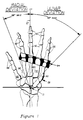
- Figure 1 is a skeletal diagram of a user's right hand.
- Figure 2 is a diagram of a user's hand resting on a preferred embodiment of the present invention in a biomechanically neutral position.
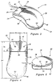
- Figure 3 is a rear isometric view of an ergonomic pointing device.
- Figure 4 is a top plan view of the pointing device of Figure 3.
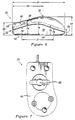
- Figure 5 is a rear elevational view of the pointing device of Figure 3.
- Figure 6 is a left side elevational view of the pointing device of Figure 3.
- Figure 7 is a bottom plan view of the pointing device of Figure 3.
- Figure 8 is a top plan view of the pointing device of Figure 3 illustrating areas of typical hand placement by a user.
- Figure 9 is a top plan view of the pointing device of Figure 3 illustrating the relative position of a rotatable ball and a grip axis.
- In order to more fully understand the present invention, it is helpful to define background concepts and terminology. In accordance with the present invention, it is believed that the majority of existing pointing devices may be difficult and uncomfortable to use, because they are too short to provide adequate support for a user's wrist and band, thereby resulting in static loads on the forearm muscles of a user. A relatively short length also encourages a user to operate the keys of the pointing device with contracted fingers, which also serves to place additional stress on the tendons of the user's hand. These loads and stresses may cause a user to experience fatigue or discomfort.
- Furthermore, some pointing devices have a relatively high back end. It is believed that this encourages a user to operate the mouse with a wrist in a raised position, which places stress on the user's upper arm and shoulder area. In addition, it is believed that the user is encouraged to control the pointing device with the larger muscle groups of the arm, which, given current mouse designs, results in a loss of accuracy in moving and actuating the pointing device.
- It is further believed that the overall shape and configuration of existing pointing devices provides visual cues and encourages all users, regardless of their hand size, to grasp the pointing device in the same manner, or "grip architecture." This is a shortcoming of existing products. Every user is different in physical size and physical proportions. As a result, the optimum operating position, defined as operation within a biomechanically neutral zone, will be different for different users.
- The preferred embodiment illustrated herein provides a pointing device that will accommodate a wide range of users, allowing them to grasp and use the pointing device in an ergonomically natural manner, thereby increasing the ease and comfort with which the pointing device may be used.
- These benefits are achieved in the preferred embodiment by quantifying and incorporating ergonomic criteria for each point of contact between a user and the pointing device, such that the user may grasp and use the pointing device in a biomechanically neutral position. Such a neutral position is achieved when the flexors and extensors of the user's hand and wrist are in equilibrium and static loads on forearm muscles and other large muscle groups are minimized. A biomechanically neutral zone specific to the wrist is achieved, if, while controlling the pointing device, it does not exceed a maximum extension of 10 degrees, a maximum radial deviation of 26 degrees, and a maximum ulnar deviation of 45 degrees. As illustrated in Figure 1, when a hand is on a flat surface radial deviation is rotation toward the thumb and ulnar deviation is rotation toward the "little finger." Both deviations are measured relative to a
vertical axis 27 passing through the center of awrist joint 31. As illustrated in Figure 2, extension is measured as the acute angle created by an inclination ofhand plane 28, as described below, relative to ahorizontal axis 29 passing through the center of thewrist joint 31. - As further illustrated in Figure 1, the five major hand bones radiating from the wrist area are
metacarpals 90, and the finger bones, totaling 14 in each hand, are calledphalanges 92. The metacarpal-phalangeal joint ridge 94 is a critical area of a hand when operating a pointing device and should be the primary location of contact with the pointing device to support the weight of the hand. As further illustrated in Figure 1, ahand plane 28 is defined by the second tofifth metacarpals 90, the metacarpals being numbered 1 through 5, beginning with the thumb. It is believed that providing this support for a user's hand plane will reduce the loads on a user's large muscle groups and shoulder. - The ranges and specific dimensions for the preferred embodiment described herein were arrived at through the use of anthropometric data, biomechanics and observation-based methodology. Given that many of the edges and surfaces of the preferred embodiment are curved, it will be appreciated by one of ordinary skill in the art that measurements taken from or to a curved edge are accurate within a range of ± 0.02 inches, and it will be appreciated by those in the art that minor deviations from the stated ranges or dimensions will not depart from the spirit of the present invention.
- It is believed that the preferred embodiment of the invention described herein provides an ergonomic pointing device that will accommodate North American adult users falling within an ergonomically defined range, from a 5th percentile female to a 95th percentile male. The range is based on hand size, a larger percentage being assigned to a larger hand, and vice versa. This means that the ergonomic pointing device described herein is believed to accommodate a group of users ranging from a woman in the 5th percentile, having a relatively small hand, to a man in the 95th percentile, having a relatively large hand. It will be appreciated that users falling outside this design range may still enjoy advantages from the preferred embodiment and that alternate preferred embodiments can be developed for other target user groups (e.g., males with hand sizes above the 95th percentile) in accordance with the present invention.
- As discussed previously, and as illustrated in Figures 2, 3 and 7, a
pointing device 20 for inputting commands into a computer (not shown) is provided with means for communicating with the computer. This means typically includes arotatable ball 82 extending from abottom surface 42 to contact a work surface 41. As a user grasps and moves the pointingdevice 20 across the work surface 41, theball 82 rotates, moving a cursor on a computer screen (not shown). The user may enter commands into the computer corresponding to the location of the cursor by depressing one ormore keys 26 provided on thepointing device 20. - Given that different people have different sized hands, it is preferred to provide a pointing device that will allow a wide range of people, as discussed above, to grasp and use the
pointing device 20 in a biomechanically neutral position. - This goal is achieved in the preferred embodiment illustrated in Figures 3-7 by providing a
pointing device 20 having a body, or housing, 24, a portion of which compriseskeys 26. As best seen in Figure 3, thebody 24 has afront end 32, aback end 34, and atop surface 36. Thetop surface 36, as seen in Figures 3 and 6, slopes upward from thefront end 32 to ahigh point 38, and slopes downward from thehigh point 38 to theback end 34. Thepointing device 20 further has twosides 78 which extend from thetop surface 36 to thebottom surface 42. Thetop surface 36 further slopes from thehigh point 38 toward thesides 78, to provide a curved, sloped surface having a bulge, orhigh point 38. Anedge 70 defined by the perimeter of thetop surface 36 is curved to minimize contact between a user and sharp edges, a portion of theedge 70 forming afront edge 46 where thefront end 32 andtop surface 36 meet, another portion of theedge 70 forming aback edge 48 where theback end 34 and thetop surface 36 meet. - Additional features of the preferred embodiment described herein include a
length 54 of thepointing device 20, aheight 50 of theback end 34, adistance 44 from thehigh point 38 to thebottom surface 42, adistance 40 from thehigh point 38 to thefront end 32 and the width of thepointing device 20. - Taking each of these features in turn, the
length 54 of thepointing device 20 is measured along thebottom surface 42 from a most forward point to a most rearward point, and is believed to contribute to preferred results if it is 4.25 inches to 4.5 inches. In a preferred embodiment, it is believed that optimum results are achieved when thelength 54 is 4.5 inches. - The
height 50 of theback end 34 is measured between a mostrearward point 52 of theback edge 48 and thebottom surface 42. It is believed that preferred results are achieved when this distance is 0.0 inch to 0.5 inch. In the preferred embodiment illustrated herein, theheight 50 is 0.5 inch. - As illustrated in Figure 6, the
distance 44 from thehigh point 38 to thebottom surface 42 is measured along a line perpendicular to thebottom surface 42 and contributes to preferred results when this distance is 1.5 to 1.6 inches. In a preferred embodiment, it is believed that optimum results are achieved when thedistance 44 is 1.587 inches. Thedistance 40 from thehigh point 38 to thefront end 32 contributes to preferred results when this distance ranges from 2.65 to 2.75 inches, and is believed to provide optimum results when it is 2.75 inches. - As illustrated in Figure 8, a width of the pointing device is measured along an arc of the
top surface 36, examples being shown by the arcs in Figure 8 marked byreference numerals joint ridge 94. For placement of a left hand of a user, the arc, or width, is measured frompoint 91 to any point along theback edge 48, for example, points 101, 103 and 105. Thearc 100 measured along thetop surface 36 betweenpoints joint ridge 94 of a left hand or a user. - Similarly, the arcs, or widths, corresponding to the placement of a right hand of a user are measured from
point 93 to a point on theback edge 48, for example, points 95, 97, and 99. The arc represented byline 106 is measured along thetop surface 36 betweenpoints joint ridge 94 of a right hand of a user. - In order to provide full support for the
joint ridge 94 of the user's hand, the width measured along an arc should be at least 2.7 inches. The cross-hatched region of Figure 8 represents an area of thetop surface 36 which meets this criteria for the width of thepointing device 20. As is illustrated by Figure 8, either a left-handed or right-handed person may grip thepointing device 20 in a variety of ways and still receive full support for the metacarpal-phalangealjoint ridge 94. In the preferred embodiment illustrated herein, the width of thepointing device 20 as illustrated ranges from 2.7 to 3.8 inches. In addition, points 91 and 93 are on a line parallel to and rearward of thefront edge 46, by a distance noted byreference numeral 21. In a preferred embodiment, thedistance 21 is 2.3 to 2.4 inches. - Another aspect of the preferred embodiment described herein, as illustrated in Figure 4, is the size of the
keys 26, which have aminimum width 72 of 0.7 inch and alength 74 of 1 inch. In a preferred embodiment, the twokeys 26 are 1.25 inches long, and 1.0 inch and 1.25 inches wide, respectively. One of thekeys 26 is larger than the other and is provided with aridge 80 to create a distinctive tactile feel, thereby allowing a user to distinguish between the twokeys 26 without having to look at thepointing device 20. In a preferred embodiment, the ridge is made of a resilient material, for example, rubber. - As illustrated in Figure 6, the
distance 96 from apoint 25 located approximately at the center of the key 26 to thebottom surface 42 is 1.0 to 1.1 inches, to further encourage the user's fingers to rest in a neutral posture. - The
preferred embodiment 20 described herein further has aminimum height 76 of 0.9 inch, measured between thetop surface 36 and thebottom surface 42 along thesides 78 of thepointing device 20 in aregion 21 from 0.8 inch rearward of thefront end 32 to at least 3.5 inches rearward of thefront end 32. Thisminimum height 76 will ensure that a thumb of a user in the group identified above will be fully supported by theside 78 of thepointing device 20, even when thepointing device 20 is gripped in different ways. - All of the above features work together to provide an ergonomic pointing device that will accommodate a wide range of users, allowing them to grasp and use the pointing device in a neutral, comfortable position. The relatively
low height 50 of theback end 34 and the gentle slope upward to thehigh point 38 provide a visual cue to users to position their lower palm on the work surface and grasp thepointing device 20 in such a manner that the bulge created by thehigh point 38 and surrounding curvature supports the metacarpal-phalangeal joint ridge. When a user grasps the pointing device in such a manner, the thumb is fully supported along theside 78 of thepointing device 20, and the fingers are allowed to rest in a neutral posture yet be in an appropriate position relative to the length of thepointing device 20, to activate thekeys 26. As illustrated in Figure 2, a neutral posture for the fingers is achieved when they are slightly curved, or bent, relative to a longitudinal axis. - By rounding the
edge 70, a user is encouraged and allowed to grasp thepointing device 20 in a variety of ways, thereby increasing the likelihood that the user will grasp and operate thepointing device 20 in a neutral position. By supporting the weight of the hand and allowing of the fingers to rest in a neutral posture, while preventing the wrist from exceeding acceptable ranges for extension and radial and ulnar deviation, the ergonomic pointing device embodying the present invention minimizes stress on the tendons of a user's hand and static loads on the forearm muscles and other large muscle groups in the upper arm and shoulder of a user. - The preferred embodiment illustrated herein provides a pointing device that increases the comfort and minimizes the fatigue associated with its use, without forfeiting accuracy. As illustrated in Figures 7 and 9, the
rotatable ball 82 is located in thebottom surface 42 near thefront end 32 of thepointing device 20. - In a preferred embodiment, a
center 81 of theball 82 is located rearward of thefront edge 46 by adistance 25 and is substantially centered relative to alateral pinch width 88, thecenter 81 being located from theleft side 78 of thepointing device 20 by adistance 27. In a preferred embodiment, thedistance 25 is 1.675 inches and thedistance 27 is 1.10 inches. - A
typical grip axis 86 is believed to be located rearward of thefront edge 46 by adistance 23. In a preferred embodiment, it is believed thedistance 23 is 1.75 to 2.0 inches. As illustrated in Figure 9, thecenter 81 of theball 82 is therefore near thegrip axis 86. By placing the center of theball 81 near thetypical grip axis 86, the user is provided with a sense of control and responsiveness. Also, given that theball 82 is relatively heavy as compared to the other components of thepointing device 20, the center of gravity of thepointing device 20 will be directed toward thecenter 81 of theball 82, further providing a sense of control. Furthermore, thelateral pinch width 88, measured along thebottom surface 42 near thefront end 32 between the twosides 78, is minimized, thereby further allowing a user to grasp the pointing device in a relaxed, lateral pinch grip architecture whereby the user may move thepointing device 20 with precision. A preferred range for thiswidth 88 is 2.15 to 2.25 inches, and in the preferred embodiment illustrated herein, thewidth 88 is 2.25 inches. - An ergonomic pointing device has been shown and described. From the foregoing, it will be appreciated that, although embodiments of the invention have been described herein for purposes of illustration, various modifications may be made without deviating from the spirit and scope of the invention. For example, although all features of the preferred embodiment described herein are believed to contribute to the improved ergonomic results of the present invention, modification or omission of an individual feature or features may be made and still gain benefits of the present invention.
Claims (31)
- A pointing device for inputting commands into a computer comprising:
a body;
a key coupled to the body; and
wherein the body is 4.25 to 4.5 inches long as measured along a bottom surface from a front end to a back end, the key being coupled to the body such that it forms a portion of the front end and of a top surface, the top surface sloping upwards from the front end to a high point, the top surface sloping downwards from the high point to the back end, the high point being 2.65 to 2.75 inches from the front end and a height of the back end being 0.0 to 0.5 inch, as measured from a back edge to the bottom surface, whereby the pointing device provides a support for a user's hand plane and encourages the user to position a lower palm on a work surface and a finger of the user to rest in a neutral posture along the top surface of the pointing device such that the keys may be activated by the fingers of the user, thereby allowing the user to grasp and actuate the pointing device in a biomechanically neutral position. - The pointing device according to claim 1 wherein the length is 4.5 inches, the distance from the high point to the front end is 2.75 inches and the height of the back end is 0.5 inch.
- The pointing device according to claim 1 wherein the high point is 1.5 to 1.6 inches from the bottom surface as measured along a line perpendicular to the bottom surface and wherein the top surface slopes gradually upward from the back end to the high point such that the pointing device supports the weight of the hand of the user when it is placed on the pointing device, while allowing the hand to remain in a neutral position.
- The pointing device according to claim 3 wherein the distance between the high point and the bottom surface measured along a line perpendicular to the bottom surface is 1.587 inches.
- The pointing device according to claim 1 wherein an area of the user's hand that should ideally be in primary contact with the pointing device is a metacarpal-phalangeal joint ridge and a width of the pointing device, measured along an arc of the top surface corresponding to a typical placement of the metacarpal-phalangeal joint ridge is at least 2.7 inches, so as to support the weight of the user's hand.
- The pointing device according to claim 5 wherein the width of the pointing device is 2.7 to 3.8 inches.
- The pointing device according to claim 1 wherein an edge, defined by the perimeter of the top surface, is rounded to eliminate contact between the user's hand and a sharp edge, thereby encouraging the user to grasp the pointing device in a variety of ways.
- The pointing device according to claim 1 wherein a width of the key is at least 0.7 inch, a length of the key is at least 1.0 inch, and a distance from a point located substantially at a center of the key is 1.0 to 1.1 inches from the bottom surface to ensure that the user can reach and activate the key with an index finger while maintaining the fingers in a neutral posture.
- The pointing device according to claim 8 wherein the length of the key is 1.25 inches.
- The pointing device according to claim 8 wherein the key is provided with a raised element made of a resilient material to allow the user to know the key is being touched without having to look at the pointing device.
- The pointing device according to claim 10 wherein the key is provided with a ridge made of a resilient material.
- The pointing device according to claim 1 wherein a height of the pointing device is at least 0.9 inch in a region along a side of the pointing device to ensure that a thumb of a user may rest in a fully supported position against the side of the pointing device.
- The pointing device according to claim 12 wherein the region of the side in which the height of the pointing device is at least 0.9 inch ranges from 0.8 inch rearward of the front end to at least 3.5 inches rearward of the front end.
- A pointing device provided with means for communicating with a computer comprising:
a housing having a front end, a top surface which slopes upward from the front end to a high point and which slopes downward from the high point to a back end, a side which extends from the top surface to a bottom surface, and an edge defined by a perimeter of the top surface, a portion of the edge forming a front edge where the front end and top surface meet and a portion of the edge forming a rear edge where the top surface and back end meet;
wherein a portion of the top surface at the front end of the housing comprises a key;
a length of the housing measured along the bottom surface is 4.25 to 4.5 inches;
the high point is 1.5 to 1.6 inches from the bottom surface as measured along a line perpendicular to the bottom surface;
the high point is 2.65 to 2.75 inches from the front edge;
the height of the back end is 0.0 to 0.5 inch as measured from a center point of the back edge to the bottom surface;
the sides of the housing are at least 0.9 inch high as measured from the top surface to the bottom surface in a region from 0.8 inch rearward of the front end to at least 3.5 inches rearward of the front end;
the edge is curved thereby minimizing user contact with sharp edges;
the top surface slopes gradually downward from the high point to the center point of the back end;
the keys are at least 0.7 inch wide and 1.0 inch long;
a width of the pointing device measured along an arc of the top surface corresponding to a typical placement of a metacarpal-phalangeal joint ridge of a user is 2.7 to 3.8 inches;
a lateral pinch width of the housing measured along the bottom surface near the front end perpendicular to the two sides is 2.15 to 2.25 inches; and
wherein the overall configuration of the pointing device supports the hand plane of a user while allowing fingers of the user to rest in a neutral posture to reach and activate the keys, a lower palm of the user may be positioned on a work surface and a thumb of the user is fully supported by a side of the housing such that the user may move and operate the pointing device while keeping the hand in a biomechanically neutral position, the pointing device encourages a user to grasp it in a variety of ways, depending on the physical size of the user's hand, and the pointing device may be accurately moved and operated while providing a sense of control and responsiveness to the user. - The pointing device according to claim 18 wherein the length of the pointing device is 4.5 inches, the high point is 1.587 inches from the bottom surface, the high point is 2.75 inches from the front edge, the height of the back end is 0.5 inch, and the lateral pinch width is 2.25 inches.
- A pointing device for inputting commands into a computer comprising:
a body; and
a key coupled to the body wherein the pointing device is shaped to support a hand plane of a user and encourage a wrist of the user to be in a biomechanically neutral position, while maintaining an ability to be moved and operated accurately by the user. - The pointing device according to claim 16 wherein the body further comprises a front end, a back end, and a top surface, the key being coupled to the body such that it forms a portion of the front end and of the top surface, the top surface sloping upwards from the front end to a high point, the top surface sloping downwards from the high point to the back end, the high point being positioned a selected distance from the front end such that it provides a support for the user's hand plane and encourages a finger of the user to rest in a neutral posture along the top surface of the pointing device such that the key may be activated by the fingers of the user, and wherein the sloping top surface and high point provide a visual cue for the user to grasp the pointing device in a neutral position.
- The pointing device according to claim 17 wherein the distance from the high point to the front end of the pointing device is 2.65 to 2.75 inches.
- The pointing device according to claim 17, further comprising:
a bottom surface for resting on a work surface, wherein a distance between the high point and the bottom surface measured along a line perpendicular to the bottom surface is 1.5 to 1.6 inches; and
wherein the top surface slopes gradually upward from the back end to the high point such that the pointing device supports the weight of the hand of the user when it is placed on the pointing device, while allowing the hand to remain in a neutral position. - The pointing device according to claim 19 further including means for communicating with a computer, the means for communicating including a rotatable ball, located in the bottom surface near the front end of the pointing device, such that the center of the rotatable ball is near a grip axis to provide the user with a feeling of responsiveness and control when positioning the pointing device.
- The pointing device according to claim 17, further comprising:
a bottom surface for resting on a work surface;
a front edge where the front end and top surface meet;
a back edge where the back end and the top surface meet; and
wherein a height of the back end measured from a center point of the back edge to the bottom surface is a selected distance whereby the user is encouraged to position a lower palm on the work surface such that the hand plane and fingers rest on the pointing device in the neutral position, thereby increasing the accuracy with which the pointing device may be positioned and activated and thereby minimizing the static loading on the user's forearm muscles and other large muscle groups. - The pointing device according to claim 21 wherein the distance between the back edge and the bottom surface is 0.0 to 0.5 inch.
- The pointing device according to claim 21 wherein a length of the product measured along the bottom surface is a selected distance such that the user is encouraged to grasp and rest the hand controlling the pointing device in a neutral position, wherein extension of the wrist, and ulnar and radial deviation of the wrist, are minimized.
- The pointing device according to claim 23 wherein the length of the pointing device is 4.25 to 4.5 inches.
- The pointing device according to claim 17 wherein an area of the user's hand that may be in primary contact with the pointing device is a metacarpal-phalangeal joint-ridge and a width of the pointing device, measured along an arc of the top surface corresponding to a typical placement of the metacarpal-phalangeal joint-ridge is a selected distance, so as to fully support the critical area of the user's hand.
- The pointing device according to claim 25 wherein the width of the pointing device is at least 2.7 inches.
- The pointing device according to claim 17 wherein an edge, defined by the perimeter of the top surface, is curved to eliminate contact between the user's hand and a sharp edge, thereby encouraging the user to grasp the pointing device in a variety of ways.
- The pointing device according to claim 17 wherein the key has a minimum width and length to ensure that the user can reach and activate the key with an index finger while maintaining the fingers in a neutral posture, and the pointing device has a minimum height in a region on a side of it to ensure that a thumb of a user may rest in a fully supported position against the side of the pointing device.
- The pointing device according to claim 28 wherein the key is at least 0.7 inch wide and 1.0 inch long and the height of the pointing device in the region on the side of the pointing device is at least 0.9 inch.
- The pointing device according to claim 28 wherein the key is provided with a raised element made of a resilient material to allow the user to know the key is being touched without having to look at the pointing device.
- The pointing device according to claim 30 wherein the key is provided with a ridge made of a resilient material.
Applications Claiming Priority (2)
| Application Number | Priority Date | Filing Date | Title |
|---|---|---|---|
| US07/957,682 US5414445A (en) | 1992-10-07 | 1992-10-07 | Ergonomic pointing device |
| US957682 | 1992-10-07 |
Publications (1)
| Publication Number | Publication Date |
|---|---|
| EP0591960A1 true EP0591960A1 (en) | 1994-04-13 |
Family
ID=25499964
Family Applications (1)
| Application Number | Title | Priority Date | Filing Date |
|---|---|---|---|
| EP93116197A Ceased EP0591960A1 (en) | 1992-10-07 | 1993-10-06 | Ergonomic pointing device |
Country Status (6)
| Country | Link |
|---|---|
| US (1) | US5414445A (en) |
| EP (1) | EP0591960A1 (en) |
| JP (1) | JPH06195170A (en) |
| KR (1) | KR940009811A (en) |
| AU (1) | AU673689B2 (en) |
| CA (1) | CA2107735C (en) |
Cited By (2)
| Publication number | Priority date | Publication date | Assignee | Title |
|---|---|---|---|---|
| EP0760116A1 (en) * | 1993-05-18 | 1997-03-05 | Ego Works Pty Ltd | Computer interface |
| WO2007000073A1 (en) * | 2005-06-27 | 2007-01-04 | Song Wang | A computer operating part |
Families Citing this family (91)
| Publication number | Priority date | Publication date | Assignee | Title |
|---|---|---|---|---|
| US6940488B1 (en) | 1994-01-06 | 2005-09-06 | Microsoft Corporation | System and method of adjusting display characteristics of a displayable data file using an ergonomic computer input device |
| US5473344A (en) * | 1994-01-06 | 1995-12-05 | Microsoft Corporation | 3-D cursor positioning device |
| US6097371A (en) | 1996-01-02 | 2000-08-01 | Microsoft Corporation | System and method of adjusting display characteristics of a displayable data file using an ergonomic computer input device |
| US7322011B2 (en) * | 1994-01-06 | 2008-01-22 | Microsoft Corporation | System and method of adjusting display characteristics of a displayable data file using an ergonomic computer input device |
| US5581277A (en) * | 1995-03-06 | 1996-12-03 | Tajiri; Akira | Anti-carpal tunnel device (ACTD) for computer operators |
| US5940738A (en) | 1995-05-26 | 1999-08-17 | Hyundai Electronics America, Inc. | Video pedestal network |
| US5726683A (en) * | 1995-08-09 | 1998-03-10 | Midas Mouse International Pty. | Ergonomic computer mouse |
| US6005553A (en) * | 1995-08-09 | 1999-12-21 | Midas Mouse International Pty. Ltd. | Ergonomic computer mouse |
| US5894302A (en) * | 1995-08-28 | 1999-04-13 | Contour Design, Inc. | Ergonomic housing for a computer mouse |
| US6396478B1 (en) | 1996-01-03 | 2002-05-28 | Softview Computer Products Corp. | Ergonomic mouse extension |
| US6157370A (en) * | 1996-01-03 | 2000-12-05 | Softview Computer Products Corp. | Ergonomic mouse extension |
| USD385542S (en) * | 1996-01-05 | 1997-10-28 | Microsoft Corporation | Pointing device |
| USD382550S (en) * | 1996-01-16 | 1997-08-19 | Microsoft Corporation | Rear portion of a pointing device |
| USD381968S (en) * | 1996-02-09 | 1997-08-05 | Kensington Microware Limited | Computer mouse |
| USD383453S (en) * | 1996-02-23 | 1997-09-09 | Contour Design, Inc. | Ergonomic housing for a computer mouse |
| US6434598B1 (en) | 1996-07-01 | 2002-08-13 | Sun Microsystems, Inc. | Object-oriented system, method and article of manufacture for a client-server graphical user interface (#9) framework in an interprise computing framework system |
| US6304893B1 (en) | 1996-07-01 | 2001-10-16 | Sun Microsystems, Inc. | Object-oriented system, method and article of manufacture for a client-server event driven message framework in an interprise computing framework system |
| US6272555B1 (en) | 1996-07-01 | 2001-08-07 | Sun Microsystems, Inc. | Object-oriented system, method and article of manufacture for a client-server-centric interprise computing framework system |
| US5999972A (en) * | 1996-07-01 | 1999-12-07 | Sun Microsystems, Inc. | System, method and article of manufacture for a distributed computer system framework |
| US5987245A (en) * | 1996-07-01 | 1999-11-16 | Sun Microsystems, Inc. | Object-oriented system, method and article of manufacture (#12) for a client-server state machine framework |
| US6266709B1 (en) | 1996-07-01 | 2001-07-24 | Sun Microsystems, Inc. | Object-oriented system, method and article of manufacture for a client-server failure reporting process |
| US6038590A (en) * | 1996-07-01 | 2000-03-14 | Sun Microsystems, Inc. | Object-oriented system, method and article of manufacture for a client-server state machine in an interprise computing framework system |
| US5848246A (en) * | 1996-07-01 | 1998-12-08 | Sun Microsystems, Inc. | Object-oriented system, method and article of manufacture for a client-server session manager in an interprise computing framework system |
| US6424991B1 (en) | 1996-07-01 | 2002-07-23 | Sun Microsystems, Inc. | Object-oriented system, method and article of manufacture for a client-server communication framework |
| US5898424A (en) * | 1996-09-30 | 1999-04-27 | Gateway 2000, Inc. | Pointing device with differing actuation forces for primary and secondary buttons |
| US6031518A (en) | 1997-05-30 | 2000-02-29 | Microsoft Corporation | Ergonomic input device |
| US6201534B1 (en) | 1997-10-03 | 2001-03-13 | Siemens Information And Communications Networks, Inc. | Trackball for single digit control of wireless terminal |
| US6496181B1 (en) | 1997-10-03 | 2002-12-17 | Siemens Information And Communication Mobile Llc | Scroll select-activate button for wireless terminals |
| GB9722766D0 (en) | 1997-10-28 | 1997-12-24 | British Telecomm | Portable computers |
| US6198471B1 (en) * | 1997-11-07 | 2001-03-06 | Brandt A. Cook | Free-floating multi-axis controller |
| US7006075B1 (en) * | 1997-11-10 | 2006-02-28 | Micron Technology Inc. | Ergonomic computer mouse |
| US7808479B1 (en) * | 2003-09-02 | 2010-10-05 | Apple Inc. | Ambidextrous mouse |
| US6064371A (en) * | 1998-02-06 | 2000-05-16 | International Business Machines Corporation | PC mouse incorporating adjustability |
| US6104383A (en) * | 1998-02-20 | 2000-08-15 | Shipman; Dale Howard | Thumb-actuated computer pointing-input device |
| US6088021A (en) * | 1998-06-03 | 2000-07-11 | Gateway, Inc. | Peripheral input device having a retractable cord |
| USD433328S (en) * | 1998-12-07 | 2000-11-07 | Glanmire Industries Limited | Container with lid |
| US6266047B1 (en) * | 1999-02-01 | 2001-07-24 | Anuthep Benja-Athon | Thumb-little-finger controlled computer mouse |
| US6373470B1 (en) | 2000-01-12 | 2002-04-16 | Apple Computer, Inc. | Cursor control device having an integral top member |
| US6292175B1 (en) | 2000-02-09 | 2001-09-18 | Logitech, Inc. | Ergonomic trackball device |
| US6509891B1 (en) * | 2000-02-09 | 2003-01-21 | Logitech Europe S.A. | Ergonomic mouse device |
| US6844873B2 (en) * | 2001-03-09 | 2005-01-18 | Peter W. Johnson | Reverse cantilever assembly for input devices |
| US6724366B2 (en) * | 2001-04-03 | 2004-04-20 | Peter James Crawford | Thumb actuated x-y input device |
| US7345671B2 (en) * | 2001-10-22 | 2008-03-18 | Apple Inc. | Method and apparatus for use of rotational user inputs |
| US7084856B2 (en) * | 2001-10-22 | 2006-08-01 | Apple Computer, Inc. | Mouse having a rotary dial |
| US7046230B2 (en) * | 2001-10-22 | 2006-05-16 | Apple Computer, Inc. | Touch pad handheld device |
| US7312785B2 (en) | 2001-10-22 | 2007-12-25 | Apple Inc. | Method and apparatus for accelerated scrolling |
| TW523939B (en) * | 2001-11-07 | 2003-03-11 | Nat Univ Chung Hsing | High-efficient light emitting diode and its manufacturing method |
| US6694895B2 (en) | 2001-11-08 | 2004-02-24 | Charles A. Gillis | Tray for supporting a computer keyboard and mouse on substantially a common horizontal plane |
| US7333092B2 (en) | 2002-02-25 | 2008-02-19 | Apple Computer, Inc. | Touch pad for handheld device |
| US7233318B1 (en) * | 2002-03-13 | 2007-06-19 | Apple Inc. | Multi-button mouse |
| US7168047B1 (en) | 2002-05-28 | 2007-01-23 | Apple Computer, Inc. | Mouse having a button-less panning and scrolling switch |
| US6921054B2 (en) | 2002-06-12 | 2005-07-26 | Jimmy-Quang V. Doan | Ergonomic mouse |
| US11275405B2 (en) | 2005-03-04 | 2022-03-15 | Apple Inc. | Multi-functional hand-held device |
| US7656393B2 (en) | 2005-03-04 | 2010-02-02 | Apple Inc. | Electronic device having display and surrounding touch sensitive bezel for user interface and control |
| US7958455B2 (en) * | 2002-08-01 | 2011-06-07 | Apple Inc. | Mode activated scrolling |
| US7358963B2 (en) * | 2002-09-09 | 2008-04-15 | Apple Inc. | Mouse having an optically-based scrolling feature |
| US20070152977A1 (en) | 2005-12-30 | 2007-07-05 | Apple Computer, Inc. | Illuminated touchpad |
| US7499040B2 (en) | 2003-08-18 | 2009-03-03 | Apple Inc. | Movable touch pad with added functionality |
| ES2304627T3 (en) | 2003-11-12 | 2008-10-16 | Research In Motion Limited | ESTABLISHMENT OF NETWORK PRIORITY WITH CAPACITY OF DATA COMMUNICATION WITH REDUCED DELAYS IN THE DATA SERVICE. |
| US7495659B2 (en) | 2003-11-25 | 2009-02-24 | Apple Inc. | Touch pad for handheld device |
| US8059099B2 (en) | 2006-06-02 | 2011-11-15 | Apple Inc. | Techniques for interactive input to portable electronic devices |
| US20070252050A1 (en) * | 2004-05-14 | 2007-11-01 | Kennedy Robert D | Hand positioner device for computer mouse |
| US20050253805A1 (en) * | 2004-05-14 | 2005-11-17 | Kennedy Robert D | Hand positioner for computer mouse |
| CN100555200C (en) | 2004-08-16 | 2009-10-28 | 苹果公司 | The method of the spatial resolution of touch sensitive devices and raising touch sensitive devices |
| US20060250364A1 (en) * | 2005-05-09 | 2006-11-09 | Alex Gorbunov | Ergonomic computer mouse |
| US7710397B2 (en) * | 2005-06-03 | 2010-05-04 | Apple Inc. | Mouse with improved input mechanisms using touch sensors |
| US7671837B2 (en) | 2005-09-06 | 2010-03-02 | Apple Inc. | Scrolling input arrangements using capacitive sensors on a flexible membrane |
| US7880729B2 (en) | 2005-10-11 | 2011-02-01 | Apple Inc. | Center button isolation ring |
| US8077147B2 (en) | 2005-12-30 | 2011-12-13 | Apple Inc. | Mouse with optical sensing surface |
| US20070152983A1 (en) | 2005-12-30 | 2007-07-05 | Apple Computer, Inc. | Touch pad with symbols based on mode |
| US20090201248A1 (en) * | 2006-07-05 | 2009-08-13 | Radu Negulescu | Device and method for providing electronic input |
| US9360967B2 (en) | 2006-07-06 | 2016-06-07 | Apple Inc. | Mutual capacitance touch sensing device |
| US8743060B2 (en) | 2006-07-06 | 2014-06-03 | Apple Inc. | Mutual capacitance touch sensing device |
| US8022935B2 (en) | 2006-07-06 | 2011-09-20 | Apple Inc. | Capacitance sensing electrode with integrated I/O mechanism |
| US7795553B2 (en) | 2006-09-11 | 2010-09-14 | Apple Inc. | Hybrid button |
| US8274479B2 (en) | 2006-10-11 | 2012-09-25 | Apple Inc. | Gimballed scroll wheel |
| US8482530B2 (en) | 2006-11-13 | 2013-07-09 | Apple Inc. | Method of capacitively sensing finger position |
| US9654104B2 (en) | 2007-07-17 | 2017-05-16 | Apple Inc. | Resistive force sensor with capacitive discrimination |
| US8683378B2 (en) | 2007-09-04 | 2014-03-25 | Apple Inc. | Scrolling techniques for user interfaces |
| WO2009032898A2 (en) | 2007-09-04 | 2009-03-12 | Apple Inc. | Compact input device |
| US8416198B2 (en) | 2007-12-03 | 2013-04-09 | Apple Inc. | Multi-dimensional scroll wheel |
| US8125461B2 (en) | 2008-01-11 | 2012-02-28 | Apple Inc. | Dynamic input graphic display |
| US8820133B2 (en) | 2008-02-01 | 2014-09-02 | Apple Inc. | Co-extruded materials and methods |
| US9454256B2 (en) | 2008-03-14 | 2016-09-27 | Apple Inc. | Sensor configurations of an input device that are switchable based on mode |
| US8816967B2 (en) | 2008-09-25 | 2014-08-26 | Apple Inc. | Capacitive sensor having electrodes arranged on the substrate and the flex circuit |
| DE102008058196A1 (en) | 2008-11-20 | 2010-06-10 | Koltai, Karl, Dr. | Multi-functional or flat mouse comprises special surfaces of adequate size on all sides of base plate, which carry multiple operating- and control elements |
| US8395590B2 (en) | 2008-12-17 | 2013-03-12 | Apple Inc. | Integrated contact switch and touch sensor elements |
| US9354751B2 (en) | 2009-05-15 | 2016-05-31 | Apple Inc. | Input device with optimized capacitive sensing |
| US8872771B2 (en) | 2009-07-07 | 2014-10-28 | Apple Inc. | Touch sensing device having conductive nodes |
| DE202010016392U1 (en) | 2010-12-10 | 2011-02-24 | Koltai, Karl, Dr. | Mouse for operating an electronic device |
| CN107063065B (en) * | 2017-01-23 | 2023-10-10 | 金华马卡科技有限公司 | Positioning equipment |
Citations (3)
| Publication number | Priority date | Publication date | Assignee | Title |
|---|---|---|---|---|
| US4862165A (en) * | 1988-02-12 | 1989-08-29 | Samuel Gart | Ergonomically-shaped hand controller |
| EP0348153A1 (en) * | 1988-06-21 | 1989-12-27 | Crosfield Electronics Limited | Position indicating device |
| EP0453587A1 (en) * | 1990-04-23 | 1991-10-30 | San-Yih Cheng | Computer mouse |
Family Cites Families (8)
| Publication number | Priority date | Publication date | Assignee | Title |
|---|---|---|---|---|
| US3835464A (en) * | 1973-01-11 | 1974-09-10 | Xerox Corp | Position indicator for a display system |
| US4559532A (en) * | 1982-08-07 | 1985-12-17 | Alps Electric Co., Ltd. | X-Y Position input device for display system |
| US4562314A (en) * | 1983-03-09 | 1985-12-31 | Alps Electric Co., Ltd. | X-Y Positions input device for display system |
| JPS6020648U (en) * | 1983-07-14 | 1985-02-13 | アルプス電気株式会社 | X-Y direction input device |
| JPS6194134A (en) * | 1984-10-13 | 1986-05-13 | Naretsuji:Kk | Radio mouse device |
| DE3630007A1 (en) * | 1985-09-05 | 1987-03-12 | Alps Electric Co Ltd | X-Y DIRECTION ENTRY DEVICE |
| US4786892A (en) * | 1986-02-22 | 1988-11-22 | Alps Electric Co., Ltd. | X-Y direction input device having changeable orientation of input axes and switch activation |
| US5252970A (en) * | 1991-01-30 | 1993-10-12 | David Baronowsky | Ergonomic multi-axis controller |
-
1992
- 1992-10-07 US US07/957,682 patent/US5414445A/en not_active Expired - Lifetime
-
1993
- 1993-10-05 CA CA002107735A patent/CA2107735C/en not_active Expired - Fee Related
- 1993-10-06 AU AU48817/93A patent/AU673689B2/en not_active Ceased
- 1993-10-06 EP EP93116197A patent/EP0591960A1/en not_active Ceased
- 1993-10-06 KR KR1019930020572A patent/KR940009811A/en not_active Application Discontinuation
- 1993-10-07 JP JP5251480A patent/JPH06195170A/en not_active Withdrawn
Patent Citations (3)
| Publication number | Priority date | Publication date | Assignee | Title |
|---|---|---|---|---|
| US4862165A (en) * | 1988-02-12 | 1989-08-29 | Samuel Gart | Ergonomically-shaped hand controller |
| EP0348153A1 (en) * | 1988-06-21 | 1989-12-27 | Crosfield Electronics Limited | Position indicating device |
| EP0453587A1 (en) * | 1990-04-23 | 1991-10-30 | San-Yih Cheng | Computer mouse |
Cited By (4)
| Publication number | Priority date | Publication date | Assignee | Title |
|---|---|---|---|---|
| EP0760116A1 (en) * | 1993-05-18 | 1997-03-05 | Ego Works Pty Ltd | Computer interface |
| EP0760116A4 (en) * | 1993-05-18 | 1997-08-06 | Ego Works Pty Ltd | Computer interface |
| US6091403A (en) * | 1993-05-18 | 2000-07-18 | Ego Works Pty. Ltd. | Computer interface |
| WO2007000073A1 (en) * | 2005-06-27 | 2007-01-04 | Song Wang | A computer operating part |
Also Published As
| Publication number | Publication date |
|---|---|
| CA2107735A1 (en) | 1994-04-08 |
| JPH06195170A (en) | 1994-07-15 |
| US5414445A (en) | 1995-05-09 |
| KR940009811A (en) | 1994-05-24 |
| AU673689B2 (en) | 1996-11-21 |
| CA2107735C (en) | 1998-09-29 |
| AU4881793A (en) | 1994-04-21 |
Similar Documents
| Publication | Publication Date | Title |
|---|---|---|
| US5414445A (en) | Ergonomic pointing device | |
| US6429852B1 (en) | Ergonomic input device | |
| US6556150B1 (en) | Ergonomic computer input device | |
| US5563628A (en) | Hand held computer cursor controller and command input device | |
| US5576733A (en) | Ergonomic computer mouse | |
| US5982356A (en) | Ergonomic computer cursor control apparatus and mount | |
| US6441805B1 (en) | Ergonomic computer mouse | |
| US7277083B2 (en) | Ergonomically designed computer gaming device | |
| US6359611B2 (en) | Finger controlled computer mouse | |
| US6590564B1 (en) | Ergonomic computer input device | |
| US7768500B2 (en) | Ergonomic pointing device | |
| US9063587B2 (en) | Computer input device with ergonomically formed and positioned actuators | |
| US20060139331A1 (en) | Ergonomic computer mouse | |
| US6922186B2 (en) | Ergonomic computer mouse | |
| US6377244B1 (en) | Ergonomic computer mouse | |
| EP0919022B1 (en) | Device for operating a mouse-operated computer program | |
| US6577298B2 (en) | Device for operating a mouse-operated computer program | |
| US20090213068A1 (en) | Ergonomic Pointing Device | |
| US20050275625A1 (en) | Ergonomic computer input device having pistol-type grip | |
| US20050030288A1 (en) | Portable and ergonomic computer input device | |
| US20040211601A1 (en) | Input device for a computer | |
| AU6717794A (en) | Computer interface | |
| EP1127333A1 (en) | Manually operated computer tracking device | |
| US11256345B2 (en) | Hand operated computer input device with palm heel support | |
| US20060176268A1 (en) | Device for inputting control signals to a peripheral unit and a combination including such a device |
Legal Events
| Date | Code | Title | Description |
|---|---|---|---|
| PUAI | Public reference made under article 153(3) epc to a published international application that has entered the european phase |
Free format text: ORIGINAL CODE: 0009012 |
|
| AK | Designated contracting states |
Kind code of ref document: A1 Designated state(s): AT BE CH DE DK ES FR GB GR IE IT LI LU MC NL PT SE |
|
| 17P | Request for examination filed |
Effective date: 19940920 |
|
| 17Q | First examination report despatched |
Effective date: 19970530 |
|
| STAA | Information on the status of an ep patent application or granted ep patent |
Free format text: STATUS: THE APPLICATION HAS BEEN REFUSED |
|
| 18R | Application refused |
Effective date: 20010812 |