EP0591712B1 - Device for marking points on the body used for medical examination - Google Patents
Device for marking points on the body used for medical examination Download PDFInfo
- Publication number
- EP0591712B1 EP0591712B1 EP93114699A EP93114699A EP0591712B1 EP 0591712 B1 EP0591712 B1 EP 0591712B1 EP 93114699 A EP93114699 A EP 93114699A EP 93114699 A EP93114699 A EP 93114699A EP 0591712 B1 EP0591712 B1 EP 0591712B1
- Authority
- EP
- European Patent Office
- Prior art keywords
- markers
- marker
- contrast
- different
- holder
- Prior art date
- Legal status (The legal status is an assumption and is not a legal conclusion. Google has not performed a legal analysis and makes no representation as to the accuracy of the status listed.)
- Expired - Lifetime
Links
Images


Classifications
-
- A—HUMAN NECESSITIES
- A61—MEDICAL OR VETERINARY SCIENCE; HYGIENE
- A61B—DIAGNOSIS; SURGERY; IDENTIFICATION
- A61B6/00—Apparatus for radiation diagnosis, e.g. combined with radiation therapy equipment
- A61B6/58—Testing, adjusting or calibrating apparatus or devices for radiation diagnosis
- A61B6/582—Calibration
- A61B6/583—Calibration using calibration phantoms
-
- A—HUMAN NECESSITIES
- A61—MEDICAL OR VETERINARY SCIENCE; HYGIENE
- A61B—DIAGNOSIS; SURGERY; IDENTIFICATION
- A61B6/00—Apparatus for radiation diagnosis, e.g. combined with radiation therapy equipment
- A61B6/12—Devices for detecting or locating foreign bodies
-
- A—HUMAN NECESSITIES
- A61—MEDICAL OR VETERINARY SCIENCE; HYGIENE
- A61B—DIAGNOSIS; SURGERY; IDENTIFICATION
- A61B90/00—Instruments, implements or accessories specially adapted for surgery or diagnosis and not covered by any of the groups A61B1/00 - A61B50/00, e.g. for luxation treatment or for protecting wound edges
- A61B90/39—Markers, e.g. radio-opaque or breast lesions markers
-
- A—HUMAN NECESSITIES
- A61—MEDICAL OR VETERINARY SCIENCE; HYGIENE
- A61B—DIAGNOSIS; SURGERY; IDENTIFICATION
- A61B90/00—Instruments, implements or accessories specially adapted for surgery or diagnosis and not covered by any of the groups A61B1/00 - A61B50/00, e.g. for luxation treatment or for protecting wound edges
- A61B90/36—Image-producing devices or illumination devices not otherwise provided for
- A61B2090/363—Use of fiducial points
-
- A—HUMAN NECESSITIES
- A61—MEDICAL OR VETERINARY SCIENCE; HYGIENE
- A61B—DIAGNOSIS; SURGERY; IDENTIFICATION
- A61B90/00—Instruments, implements or accessories specially adapted for surgery or diagnosis and not covered by any of the groups A61B1/00 - A61B50/00, e.g. for luxation treatment or for protecting wound edges
- A61B90/39—Markers, e.g. radio-opaque or breast lesions markers
- A61B2090/3904—Markers, e.g. radio-opaque or breast lesions markers specially adapted for marking specified tissue
- A61B2090/3916—Bone tissue
-
- A—HUMAN NECESSITIES
- A61—MEDICAL OR VETERINARY SCIENCE; HYGIENE
- A61B—DIAGNOSIS; SURGERY; IDENTIFICATION
- A61B90/00—Instruments, implements or accessories specially adapted for surgery or diagnosis and not covered by any of the groups A61B1/00 - A61B50/00, e.g. for luxation treatment or for protecting wound edges
- A61B90/39—Markers, e.g. radio-opaque or breast lesions markers
- A61B2090/3995—Multi-modality markers
-
- A—HUMAN NECESSITIES
- A61—MEDICAL OR VETERINARY SCIENCE; HYGIENE
- A61B—DIAGNOSIS; SURGERY; IDENTIFICATION
- A61B90/00—Instruments, implements or accessories specially adapted for surgery or diagnosis and not covered by any of the groups A61B1/00 - A61B50/00, e.g. for luxation treatment or for protecting wound edges
- A61B90/10—Instruments, implements or accessories specially adapted for surgery or diagnosis and not covered by any of the groups A61B1/00 - A61B50/00, e.g. for luxation treatment or for protecting wound edges for stereotaxic surgery, e.g. frame-based stereotaxis
Definitions
- the invention relates to a device for marking body areas for imaging medical examination methods, such as, in particular, magnetic resonance imaging, computed tomography, X-ray or PET, with holders which can be fastened to the body and / or a stereotactic device and markers which can be fastened to the holders and which have a high contrast when producing the image Contain substance.
- medical examination methods such as, in particular, magnetic resonance imaging, computed tomography, X-ray or PET
- holders which can be fastened to the body and / or a stereotactic device and markers which can be fastened to the holders and which have a high contrast when producing the image Contain substance.
- stereotactic operations i.e. brain operations, in which a probe or electrode is pushed through a small opening drilled in the bony skull with the protection of neighboring sensitive structures to a deep brain or nerve nucleus with the help of a target device attached to the patient's head Studies on the anatomical structure required.
- marker systems are attached to the patient, as is known from GB-A-2212371.
- the aim of the invention is to provide a device for marking body areas for imaging medical examination methods, with which different examination methods can be used to complement one another in a simple manner.
- the holders of the marker system consist of a material which does not interfere with the image generation in at least two different image-producing examination methods.
- Such marker systems for frameless stereotaxy are attached to the patient. They consist of the brackets mentioned above and the actual markers, i.e. H. those elements which contain a substance which is particularly rich in contrast for the medical examination procedure to be carried out in order to appear clearly on the image.
- the brackets are designed so that they can be implanted, glued to the surface of the body, attached to mask systems or attached to stereotactic systems.
- the markers (markers) themselves can then be exchangeably attached to the brackets.
- the markers each contain a substance or essentially consist of a substance that has good image contrast in the imaging process. Magnetic resonance imaging, computed tomography, X-ray analysis or PET examination are particularly considered as imaging methods today.
- the markers are preferably also designed such that they can be optically recorded with a video camera and / or recognized with an operating microscope.
- the surgical microscope enables position feedback, which enables precise localization.
- the position of a patient, in particular also the position of his head, in space can be determined with at least three differently positioned markers. If different examinations are now carried out on the patient with different imaging medical examination methods, as exemplified above, then both the examination and possibly a surgical intervention can be improved or facilitated by using different examination methods in addition to one another. If the relative position of the patient (e.g. his head) is precisely determined for the images obtained with different methods, then the various image-generating examination methods can be superimposed on one another, e.g. purely arithmetically in a computer.
- Different anatomical information is obtained through the different properties of the various imaging medical examination methods.
- digital subtraction angiography can be used to produce good x-rays of the blood vessels in the brain.
- Magnetic resonance imaging often provides good images of edema.
- Computed tomography provides good representations of the bone structures as well as the density information required for radiation therapy.
- the invention makes it possible to superimpose and / or compare the results obtained with different image generation methods under high accuracy requirements, such as those which apply in particular in the head area.
- the solution according to the invention outlined above achieves that the markers according to the invention are rich in contrast without changing their location in various imaging methods.
- Holders for the markers are used, which are characterized by shape and material in such a way that they do not significantly interfere with the imaging of the markers and the anatomical structures.
- the markers are designed in such a way that they each have a suitable material for their casing and the actual contrast agent for different imaging processes. Such markers can then optionally be exchanged depending on the imaging method, the holders remaining unchanged.
- the holders, the markers and the contrast medium are made of materials that are approved for the respective purpose. It should be noted that only the brackets come into direct contact with the patient.
- projection images such as X-ray images
- two images from different directions are sufficient to be able to determine the location for any points.
- target points and surgical access routes can be defined and transferred to the patient, while simultaneously using a stereotaxy system in one of the imaging methods or a surgical microscope, which allows the markers to be targeted and their position in space determined.
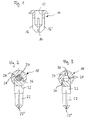
- Fig. 1 shows a holder which can be attached to a mask system known as such. 1 consists of plastic and has a recess 12 into which a marker described in more detail below can be inserted.
- the plastic holder has two spreading wings 16, 16 ', between which a slot 14 is left free.
- FIG. 2 and 3 each show a marker 18 which can be used with a holder 10 according to FIG. 1.
- a marker 18 contains a high-contrast substance 20 for the medical imaging test method currently being used. Examples of the materials are known to the person skilled in the art and are given further below.
- the marker 18 has a foot 22 which can be inserted into the recess 12 of the holder 10 with a precise fit and with a clamping effect.
- the foot 22 has a slot 22 'in order to achieve the clamping effect.
- the foot 22 of the marker 18 merges into a head 24 in which a cavity 28 is provided for receiving the high-contrast substance 20.
- a bore 26 is provided in the head 24, into which a pin 32 can be inserted with a precise fit.
- the substance 20 in the head 24 permits a computed tomography image on the one hand and, after exchanging the marker, on the other hand an X-ray image.
- the bracket 10 used in each case (FIG. 1) is not changed. This is not necessary because the material from which the holder 10 is made does not interfere with either the computed tomography or the X-ray image.
- FIG. 3 differs from the embodiment of FIG. 2 described above in that a channel 30 is formed in the head 24 through which a high-contrast substance can be injected into the cavity 28.
- a high-contrast substance can be injected into the cavity 28.
- This can e.g. be a contrast agent containing gadolinium.
- the channel 30 is then closed with a suitable means.
- the channel 30 can also be designed so that the surface tension of the contrast medium (which is a liquid) prevents leakage.
- the markers 18 according to FIGS. 2 and 3 are identical in terms of their outer dimensions and adapted to the dimensions of the holder 10, so that they can be inserted into the holder 10 optionally and with different high-contrast substances.
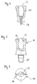
- FIG. 4 shows a holder 10 that can be implanted in the body.
- the recess 12 again serves to hold a marker (for example corresponding to FIGS. 2 and 3), while a screw 34 serves to hold the holder 10 on a bone, for example a skull bone.
- the holder 10 also consists of a body-compatible plastic, while the screw 34 is a metallic bone screw.
- FIG. 5 and 6 show a further embodiment of a holder 10, wherein the holder 10 can be used with an already implanted bone screw.
- the bracket 10 is screwed onto the already fixed bone screw with a foot 34 '.
- a slot 36 is provided for receiving a screwdriver.
- FIGS. 7 and 8 show a further embodiment of a holder, which this time can be glued to a body surface.
- the holder 10 has an approximately bell-shaped body with a recess 12 ', into which a foot 22 corresponding to FIGS. 2 and 3 can be inserted analogously to the above exemplary embodiments according to FIGS. 1, 4 and 5.
- a plate 38 serves to fix the holder 10 on, for example, the skin.
- the plate 38 is fastened with a suitable adhesive.
- FIG. 8 shows a top view of the exemplary embodiment according to FIG. 7 described above.
- FIG. 9 and 10 show a holder 10 which can be attached to a stereotaxy system.
- the holder 10 is designed in the form of a pin (FIG. 10). This pin can be inserted into a hole until the thicker cross section stops of the stereotaxy system. Then a marker 18, z. 2 and 3, can be inserted into the recess 12 ''.
- FIG. 9 shows a view of the pin in the direction of arrow P according to FIG. 10. The pin forms the holder 10 according to FIG. 10.
- a slot 14 can be seen which creates a clamping effect in a bore in a stereotaxy system.
- FIG. 11 shows a further exemplary embodiment of a marker 18, that is to say a modification of the markers described in FIGS. 2 and 3.
- the foot 22 is used here again to fasten the marker in a holder, for example in accordance with FIGS. 1 and 4 to 10.
- the head 24 of the marker 18 in accordance with FIG Frees cavity 28 into which the contrast medium can be entered.
- the cover 40 which is designed as a screw closure, is provided on its bottom with a hemispherical recess which complements a complementary hemispherical recess in the head 24 to form a solid sphere.
- Fig. 11 also shows a thread 44 for screwing the cover 40 into the head 24 and a slot 42, which serves to receive a screwdriver.
- the head 24 and the foot 22 and also the lid 40 can be made of Teflon.
- FIGS. 12 and 13 show a further exemplary embodiment of a marker 18.
- the foot 22a is again inserted into a holder 10 (for example according to FIGS. 1, 4-10).
- the marker 18 has an arm-like transverse body 24a which extends transversely to the foot 22a and has more than one cavity for receiving high-contrast substances, namely the cavities 28a, 28b and 28c. These cavities can absorb different contrast agents at the same time.
- a channel 48 connects the cavity 28b to the outside.
- the cavities 28a, 28c are each sealable to the outside by plugs 46 or 46 '.
- the plugs can be glued, for example.
- the geometric center of the two outer cavities 28a, 28c coincides with the center of the central cavity 28b.
- FIGS. 15 to 17 show a further exemplary embodiment of a marker 18 which can simultaneously take up different exchangeable contrast media.
- a plurality of continuous, cylindrical cavities 52a to 52d are formed in the head 24a of the marker 18, into which inserts according to FIGS. 18 to 20 can be inserted, in each of which the contrast medium can be contained. Inserts 60 corresponding to FIGS. 18 to 20 can therefore be inserted into each of the cavities 52a to 52d.
- the center point of the individual insertable inserts with the marking contrast agents lies on the same axis, in the exemplary embodiment shown the longitudinal axis of the marker 18 and its foot 22. In particular, it can also be achieved that the geometric center point of two outer markers with the center point of a centrally arranged one Markers collapses.
- An insert 60 has an outer tube 62, for example made of PTFE.
- Rods 64 and 66 can be inserted into the tube 62 from both ends such that a hollow space remains in the center of the tube, into which a high-contrast substance (high-contrast for the imaging test method currently used) can be input.
- the cavity 28 is initially without a filling.
- the rods 64 and 66a are designed to be removable from the hose 62 so that the user can optionally fill the cavity 28 with the desired contrast agent.
- 21 and 22 show a further exemplary embodiment of a marker 18 which is similar to the exemplary embodiment according to FIGS. 15 and 16, but inserts of different sizes can be inserted into the individual cavities. Inserts with a smaller diameter can be inserted into the cavities 54, while an insert with a larger diameter can be inserted into the cavity 56. It can also be achieved with this that the geometric center of two outer markers coincides with the center of the marker arranged in the center.
- Polysulfone in particular comes into consideration as materials for the holders, in particular the feet and the body of the holders according to FIGS. 1, 4, 5, 7 etc.
- Polysulfone is suitable as an implant, can be sterilized and is transparent so that it enables the filling material to be assigned optically.
- material for a marker 18 for example according to FIGS. 2 and 3, comes in particular polysulfone or metal, such as. B. titanium into consideration.
- polysulfone is also suitable and a commercially available electrode adhesive ring for the base plate 38.
- a holder according to FIGS. 9 and 10 can for example consist of polyamide, polyamideimide or a similar plastic.
- a marker 18 according to FIG. 11 can consist, for example, of PTFE (Teflon) or PSU or another plastic suitable as an implant.
- the markers in particular the markers 18 according to FIGS. 2 and 3 are distinguished by spherical symmetry and thus depict the same in every direction of view. This enables a clear position determination in sectional images, projection images and also with optical methods.
- the markers can be imaged simultaneously in a plurality of imaging methods on the basis of a triple or multiple symmetry, it being possible for a number of contrast media to be used at the same time (exemplary embodiments according to FIGS. 12 and 15 to 22). Markers can be used that contain different contrast agents at the same time.
- a contrast medium can be used in this way, which is well reproduced both in magnetic resonance imaging and in computer tomography.
- the exemplary embodiments shown also have the property (FIGS. 2, 3) that the center of a spherical contrast medium coincides with a clearly defined, optically recognizable center of the marker 18, which is in particular spherical.
Description
Die Erfindung betrifft eine Vorrichtung zum Markieren von Körperstellen für bilderzeugende medizinische Untersuchungsverfahren, wie insbesondere Kernspintomographie, Computertomographie, Röntgen- oder PET, mit am Körper und/oder einer stereotaktischen Einrichtung befestigbaren Halterungen und jeweils an den Halterungen befestigbaren Markern, die eine bei der Bilderzeugung kontrastreiche Substanz enthalten.The invention relates to a device for marking body areas for imaging medical examination methods, such as, in particular, magnetic resonance imaging, computed tomography, X-ray or PET, with holders which can be fastened to the body and / or a stereotactic device and markers which can be fastened to the holders and which have a high contrast when producing the image Contain substance.
Insbesondere für stereotaktische Operationen, also Gehirnoperationen, bei denen mit Hilfe eines am Kopf des Patienten befestigten Zielgerätes eine Sonde oder Elektrode durch eine kleine in den knöchernen Schädel gebohrte Öffnung unter Schonung benachbarter empfindlicher Strukturen millimetergenau zu einer tiefliegenden Hirnbahn oder einem Nervenkern vorgeschoben wird, sind hochpräzise Untersuchungen über die anatomische Struktur erforderlich.Particularly precise for stereotactic operations, i.e. brain operations, in which a probe or electrode is pushed through a small opening drilled in the bony skull with the protection of neighboring sensitive structures to a deep brain or nerve nucleus with the help of a target device attached to the patient's head Studies on the anatomical structure required.
Hierzu werden sogenannte Markersysteme am Patienten angebracht, wie aus GB-A-2212371 bekannt.For this purpose, so-called marker systems are attached to the patient, as is known from GB-A-2212371.
Die Erfindung hat das Ziel, eine Vorrichtung zum Markieren von Körperstellen für bilderzeugende medizinische Untersuchungsverfahren zu schaffen, mit der unterschiedliche Untersuchungsverfahren in einfacher Weise einander ergänzend eingesetzt werden können.The aim of the invention is to provide a device for marking body areas for imaging medical examination methods, with which different examination methods can be used to complement one another in a simple manner.
Erfindungsgemäß wird diese Aufgabe dadurch gelöst, daß die Halterungen des Markersystems aus einem Material bestehen, das bei zumindest zwei verschiedenen bilderzeugenden Untersuchungsverfahren die Bild- erzeugung nicht stört.According to the invention, this object is achieved in that the holders of the marker system consist of a material which does not interfere with the image generation in at least two different image-producing examination methods.
Solche Markersysteme für die rahmenlose Stereotaxie werden am Patienten angebracht. Sie bestehen aus den oben genannten Halterungen und den eigentlichen Markern, d. h. denjenigen Elementen, die eine Substanz enthalten, welche für das durchzuführende medizinische Untersuchungsverfahren besonders kontrastreich ist, um auf dem Bild deutlich zu erscheinen. Die Halterungen sind dabei so ausgeführt, daß sie implantiert, auf die Körperoberfläche aufgeklebt, an Maskensystemen befestigt oder an Stereotaxiesystemen angebracht werden können. Die Marker (Markierer) selbst lassen sich dann an den Halterungen auswechselbar befestigen. Die Marker enthalten dabei jeweils eine Substanz oder bestehen im wesentlichen aus einer solchen Substanz, die einen guten Bildkontrast in dem bildgebenden Verfahren aufweist. Als bildgebendes Verfahren kommen insbesondere heute in Betracht die Kernspintomographie, die Computertomographie, die Röntgenanalyse oder die PET-Untersuchung.Such marker systems for frameless stereotaxy are attached to the patient. They consist of the brackets mentioned above and the actual markers, i.e. H. those elements which contain a substance which is particularly rich in contrast for the medical examination procedure to be carried out in order to appear clearly on the image. The brackets are designed so that they can be implanted, glued to the surface of the body, attached to mask systems or attached to stereotactic systems. The markers (markers) themselves can then be exchangeably attached to the brackets. The markers each contain a substance or essentially consist of a substance that has good image contrast in the imaging process. Magnetic resonance imaging, computed tomography, X-ray analysis or PET examination are particularly considered as imaging methods today.
Bevorzugt sind erfindungsgemäß die Marker auch so ausgeführt, daß sie optisch mit einer Videokamera aufnehmbar und/oder mit einem Operationsmikroskop erkennbar sind. Das Operationsmikroskop ermöglicht eine Positionsrückmeldung, mit der eine genaue Lokalisierung ermöglicht ist.According to the invention, the markers are preferably also designed such that they can be optically recorded with a video camera and / or recognized with an operating microscope. The surgical microscope enables position feedback, which enables precise localization.
Mit mindestens drei unterschiedlich positionierten Markern kann die Lage eines Patienten, insbesondere auch die Lage seines Kopfes, im Raum bestimmt werden. Werden nun am Patienten unterschiedliche Untersuchungen mit verschiedenen bilderzeugenden medizinischen Untersuchungsverfahren, wie sie oben beispielhaft aufgeführt sind, durchgeführt, so kann sowohl die Untersuchung als auch gegebenenfalls ein chirurgischer Eingriff dadurch verbessert bzw. erleichtert werden, daß unterschiedliche Untersuchungsverfahren einander ergänzend eingesetzt werden. Ist für die mit verschiedenen Verfahren gewonnenen Bilder jeweils die relative Position des Patienten (z. B. seines Kopfes) genau bestimmt, dann können die verschiedenen bilderzeugenden Untersuchungsverfahren einander überlagert werden, z.B. rein rechnerisch in einem Computer.The position of a patient, in particular also the position of his head, in space can be determined with at least three differently positioned markers. If different examinations are now carried out on the patient with different imaging medical examination methods, as exemplified above, then both the examination and possibly a surgical intervention can be improved or facilitated by using different examination methods in addition to one another. If the relative position of the patient (e.g. his head) is precisely determined for the images obtained with different methods, then the various image-generating examination methods can be superimposed on one another, e.g. purely arithmetically in a computer.
Durch die unterschiedlichen Eigenschaften der verschiedenen bilderzeugenden medizinischen Untersuchungsverfahren werden unterschiedliche anatomische Informationen gewonnen. Beispielsweise können mit der digitalen Subtraktionsangiographie gute Röntgenbilder der Blutgefäße im Gehirn hergestellt werden. Die Kernspintomographie liefert häufig gute Bilder von Ödemen. Die Computertomographie hingegen liefert gute Darstellungen der Knochenstrukturen sowie die für eine Strahlentherapie nötigen Dichteinformationen.Different anatomical information is obtained through the different properties of the various imaging medical examination methods. For example, digital subtraction angiography can be used to produce good x-rays of the blood vessels in the brain. Magnetic resonance imaging often provides good images of edema. Computed tomography, on the other hand, provides good representations of the bone structures as well as the density information required for radiation therapy.
Die Erfindung ermöglicht es, unter hohen Genauigkeitsanforderungen, wie sie insbesondere im Kopfbereich gelten, die mit verschiedenen Bilderzeugungsverfahren gewonnenen Ergebnisse einander zu überlagern und/oder zu vergleichen.The invention makes it possible to superimpose and / or compare the results obtained with different image generation methods under high accuracy requirements, such as those which apply in particular in the head area.
Die oben skizzierte erfindungsgemäße Lösung erreicht, daß die erfindungsgemäßen Marker sich ohne Ortsveränderung in verschiedenen bildgebenden Verfahren kontrastreich darstellen. Es werden Halterungen für die Marker verwendet, die sich durch Form und Material so auszeichnen, daß sie die Abbildung der Marker und der anatomischen Strukturen nicht nennenswert stören.The solution according to the invention outlined above achieves that the markers according to the invention are rich in contrast without changing their location in various imaging methods. Holders for the markers are used, which are characterized by shape and material in such a way that they do not significantly interfere with the imaging of the markers and the anatomical structures.
Die Marker sind so ausgelegt, daß sie für verschiedene bildgebende Verfahren jeweils ein geeignetes Material für ihre Hülle sowie das eigentliche Kontrastmittel aufweisen. Solche Marker können dann wahlweise je nach dem bildgebenden Verfahren ausgewechselt werden, wobei die Halterungen unverändert bleiben.The markers are designed in such a way that they each have a suitable material for their casing and the actual contrast agent for different imaging processes. Such markers can then optionally be exchanged depending on the imaging method, the holders remaining unchanged.
Die Halterungen, die Marker und das Kontrastmittel bestehen aus Materialien, die für den jeweiligen Zweck zugelassen sind. Zu beachten ist dabei, daß nur die Halterungen in direkten Kontakt mit dem Patienten kommen.The holders, the markers and the contrast medium are made of materials that are approved for the respective purpose. It should be noted that only the brackets come into direct contact with the patient.
Bei sogenannten Projektionsbildern, wie Röntgenaufnahmen, genügen zwei Aufnahmen aus unterschiedlicher Richtung, um für beliebige Punkte eine Ortsbestimmung durchführen zu können.In so-called projection images, such as X-ray images, two images from different directions are sufficient to be able to determine the location for any points.
Bei sogenannten Schnittbildern genügen Aufnahmen, die die Marker sichtbar enthalten, um eine Ortsbestimmung im Raum durchführen zu können.In the case of so-called sectional images, recordings that contain the markers visibly are sufficient to be able to determine the location in space.
Für stereotaktisch geführte Eingriffe müssen zur Übertragung der vorbestimmten Zielpunkte auf das Stereotaxiesystem dann noch zusätzliche Aufnahmen gemacht werden, die sowohl die Marker als auch die Position des Stereotaxiesystems sichtbar enthalten. Dabei können unterschiedliche bildgebende Verfahren eingesetzt werden. Auf diese Weise können Zielpunkte und chirurgische Zugangswege festgelegt und auf den Patienten übertragen werden, wobei gleichzeitig ein Stereotaxiesystem in einem der bildgebenden Verfahren oder ein Operationsmikroskop verwendet wird, welches es erlaubt, die Marker anzupeilen und deren Position im Raum zu bestimmen.For stereotactically guided interventions, additional recordings must then be made to transmit the predetermined target points to the stereotaxy system, which contain both the markers and the position of the stereotaxy system visibly. Different imaging methods can be used. In this way, target points and surgical access routes can be defined and transferred to the patient, while simultaneously using a stereotaxy system in one of the imaging methods or a surgical microscope, which allows the markers to be targeted and their position in space determined.
Nachfolgend werden mehrere Ausführungsbeispiele von Halterungen und zugeordneten Markern näher beschrieben.Several exemplary embodiments of holders and associated markers are described in more detail below.
Es zeigt:
- Fig. 1
- eine Halterung zum Befestigen von Markern;
- Fig. 2
- ein erstes Ausführungsbeispiel eines Markers, der mit einer Halterung gemäß Fig. 1 eingegesetzt werden kann;
- Fig. 3
- ein zweites Ausführungsbeispiel eines Markers, der ebenfalls mit einer Halterung gemäß Fig. 1 einsetzbar ist;
- Fig. 4
- ein weiteres Ausführungsbeispiel einer Haltetung;
- Fig. 5
- noch ein Ausführungsbeispiel einer Halterung;
- Fig. 6
- eine Draufsicht auf eine Halterung gemäß Fig. 5;
- Fig. 7
- ein anderes Ausführungsbeispiel einer Halterung mit einer Fußplatte;
- Fig. 8
- eine Draufsicht auf eine Halterung gemäß Fig. 7;
- Fig. 9
- eine Ansicht der Halterung gemäß Fig. 10 in Richtung des Pfeiles P;
- Fig. 10
- ein Ausführungsbeispiel einer Halterung, die an einem Stereotaxiesystem befestigbar ist;
- Fig. 11
- ein weiteres Ausführungsbeispiel eines Markers, der beispielsweise mit einer der vorstehend genannten Halterungen verwendbar ist;
- Fig. 12
- ein Ausführungsbeispiel eines Markers, in den verschiedene Kontrastsubstanzen einbringbar sind;
- Fig. 13
- eine Ansicht des Markers gemäß Fig. 12 in Richtung des Pfeiles P;
- Fig. 14
- eine Draufsicht auf den Marker gemäß Fig. 12;
- Fig. 15
- ein weiteres Ausführungsbeispiel eines Markers mit mehreren Aufnahmen für unterschiedliche Kontrast-Substanzen;
- Fig. 16
- einen Axialschnitt durch einen Marker gemäß Fig. 15;
- Fig. 17
- einen Schnitt senkrecht zur Längsachse eines Markers gemäß Fig. 15;
- Fig. 18
bis 20 - unterschiedliche Ausgestaltungen von Einschüben, die bei Markern gemäß den Fig. 15, 21
und 22 verwendbar sind; - Fig. 21
- ein weiteres Ausführungsbeispiel eines Markers in Abwandlung des Ausführungsbeispiels gemäß Fig. 15 und
- Fig. 22
- einen Axialschnitt durch einen Marker gemäß Fig. 21.
- Fig. 1
- a holder for attaching markers;
- Fig. 2
- a first embodiment of a marker that can be used with a holder according to Figure 1;
- Fig. 3
- a second embodiment of a marker, which can also be used with a holder according to FIG. 1;
- Fig. 4
- another embodiment of a bracket;
- Fig. 5
- another embodiment of a bracket;
- Fig. 6
- a plan view of a holder according to FIG. 5;
- Fig. 7
- another embodiment of a holder with a base plate;
- Fig. 8
- a plan view of a holder according to FIG. 7;
- Fig. 9
- a view of the bracket of Figure 10 in the direction of arrow P;
- Fig. 10
- an embodiment of a bracket that can be attached to a stereotaxy system;
- Fig. 11
- a further embodiment of a marker, which can be used for example with one of the above-mentioned holders;
- Fig. 12
- an embodiment of a marker in which different contrast substances can be introduced;
- Fig. 13
- a view of the marker of FIG 12 in the direction of arrow P;
- Fig. 14
- a plan view of the marker of FIG. 12;
- Fig. 15
- a further embodiment of a marker with several recordings for different contrast substances;
- Fig. 16
- an axial section through a marker according to FIG. 15;
- Fig. 17
- a section perpendicular to the longitudinal axis of a marker according to FIG. 15;
- 18 to 20
- different configurations of inserts that can be used with markers according to FIGS. 15, 21 and 22;
- Fig. 21
- another embodiment of a marker in a modification of the embodiment of FIG. 15 and
- Fig. 22
- an axial section through a marker according to FIG. 21.
Fig. 1 zeigt eine Halterung, die an einem als solches bekannten Maskensystem befestigbar ist. Die Halterung 10 gemäß Fig. 1 besteht aus Kunststoff und weist eine Ausnehmung 12 auf, in welche ein weiter unten näher beschriebener Marker einschiebbar ist. Die Halterung aus Kunststoff weist zwei Spreizflügel 16, 16' auf, zwischen denen ein Schlitz 14 freigelassen ist.Fig. 1 shows a holder which can be attached to a mask system known as such. 1 consists of plastic and has a
Die Fig. 2 und 3 zeigen jeweils einen Marker 18, der mit einer Halterung 10 gemäß Fig. 1 verwendbar ist.2 and 3 each show a
Ein Marker 18 enthält eine kontrastreiche Substanz 20 für das gerade angewandte medizinische bilderzeugende Untersuchungsverfahren. Beispiele für die Materialien sind dem Fachmann bekannt und werden weiter unten noch angegeben.A
Der Marker 18 weist einen Fuß 22 auf, der in die Ausnehmung 12 der Halterung 10 paßgenau unter Klemmwirkung einschiebbar ist. Hierzu weist der Fuß 22 einen Schlitz 22' auf, um die Klemmwirkung zu erzielen.The
Der Fuß 22 des Markers 18 geht in einen Kopf 24 über, in dem ein Hohlraum 28 zur Aufnahme der kontrastreichen Substanz 20 vorgesehen ist. Gemäß den Figuren 2 und 3 ist im Kopf 24 eine Bohrung 26 vorgesehen, in die ein Stift 32 paßgenau einschiebbar ist.The
Beispielsweise erlaubt die Substanz 20 im Kopf 24 einmal eine Computertomographie-Aufnahme und, nach Austausch des Markers, zum anderen eine Röntgenaufnahme. Dabei wird die jeweils verwendete Halterung 10 (Fig. 1) nicht geändert. Dies ist nicht erforderlich, weil das Material, aus dem die Halterung 10 besteht, sowohl die Computertomographie als auch die Röntgenaufnahme nicht stört.For example, the
Das Ausführungsbeispiel gemäß Fig. 3 unterscheidet sich vom vorstehend beschriebenen Ausführungsbeispiel nach Fig. 2 dadurch, daß im Kopf 24 ein Kanal 30 ausgebildet ist, durch den eine kontrastreiche Substanz in den Hohlraum 28 injizierbar ist. Dies kann z.B. ein Gadolinium-haltiges Kontrastmittel sein. Danach wird der Kanal 30 mit einem geeigneten Mittel verschlossen.The embodiment of FIG. 3 differs from the embodiment of FIG. 2 described above in that a
Der Kanal 30 kann auch so ausgeführt sein, daß die Oberflächenspannung des Kontrastmittels (welches eine Flüssigkeit ist) ein Auslaufen verhindert.The
Die Marker 18 gemäß den Fig. 2 und 3 sind hinsichtlich ihrer äußeren Abmessungen gleich und an die Abmessungen der Halterung 10 angepaßt, so daß sie wahlweise und mit jeweils anderen kontrastreichen Substanzen in die Halterung 10 einschiebbar sind.The
Fig. 4 zeigt eine in den Körper implantierbare Halterung 10. Dabei dient die Ausnehmung 12 wieder zur Aufnahme eines Markers (z. B. entsprechend den Fig. 2 und 3), während eine Schraube 34 dazu dient, die Halterung 10 an einem Knochen, beispielsweise einem Schädelknochen, zu befestigen. Wie bei den obigen Ausführungsbeispielen, besteht auch hier die Halterung 10 aus einem körperverträglichen Kunststoff, während die Schraube 34 eine metallische Knochenschraube ist.FIG. 4 shows a
Die Fig. 5 und 6 zeigen eine weitere Ausführungsform eines Halters 10, wobei die Halterung 10 mit einer bereits implantierten Knochenschraube verwendbar ist. Die Halterung 10 wird mit einem Fuß 34' auf die bereits festsitzende Knochenschraube aufgedreht. Am proximalen Ende der Halterung 10 ist ein Schlitz 36 zur Aufnahme eines Schraubendrehers vorgesehen.5 and 6 show a further embodiment of a
Die Fig. 7 und 8 zeigen ein weiteres Ausführungsbeispiel einer Halterung, welche diesmal auf eine Körperoberfläche aufklebbar ist. Die Halterung 10 weist einen etwa glockenförmigen Körper mit einer Ausnehmung 12' auf, in die analog den obigen Ausführungsbeispielen gemäß den Fig. 1, 4 und 5 ein Fuß 22 entsprechend den Fig. 2 und 3 einschiebbar ist. Eine Platte 38 dient der Fixierung der Halterung 10 auf beispielsweise der Haut. Dabei wird die Platte 38 mit einem geeigneten Kleber befestigt.7 and 8 show a further embodiment of a holder, which this time can be glued to a body surface. The
Fig. 8 zeigt eine Draufsicht des vorstehend beschriebenen Ausführungsbeispiels nach Fig. 7.FIG. 8 shows a top view of the exemplary embodiment according to FIG. 7 described above.
Die Fig. 9 und 10 zeigen eine Halterung 10, die an einem Stereotaxiesystem befestigbar ist. Hierzu ist die Halterung 10 in der Form eines Stiftes (Fig. 10) ausgebildet. Dieser Stift kann bis zum Anschlag des dickeren Querschnitts in eine Bohrung des Stereotaxiesystems gesteckt werden. Anschließend kann dann ein Marker 18, z. B. gemäß den Fig. 2 und 3, in die Ausnehmung 12'' eingesetzt werden. Fig. 9 zeigt eine Ansicht auf den Stift in Richtung des Pfeiles P gemäß Fig. 10. Der Stift bildet die Halterung 10 gemäß Fig. 10. Zu erkennen ist ein Schlitz 14, der in einer Bohrung eines Stereotaxiesystems eine Klemmwirkung erzeugt.9 and 10 show a
Fig. 11 zeigt ein weiteres Ausführungsbeispiel eines Markers 18, also eine Abwandlung der in den Fig. 2 und 3 beschriebenen Marker. Der Fuß 22 dient auch hier wieder der Befestigung des Markers in einer Halterung, beispielsweise entsprechend den Fig. 1 und 4 bis 10. Der Kopf 24 des Markers 18 nach Fig. 11 ist mit einem Deckel 40 versehen, der in abgenommenem Zustand einen Zugang zum Hohlraum 28 freigibt, in den das Kontrastmittel eingebbar ist. Der als Schraubverschluß ausgeführte Deckel 40 ist an seinem Boden mit einer halbkugelförmigen Ausnehmung versehen, welche eine komplementäre halbkugelförmige Ausnehmung im Kopf 24 zu einer Vollkugel ergänzt. Fig. 11 zeigt noch ein Gewinde 44 zum Einschrauben des Deckels 40 in den Kopf 24 und einen Schlitz 42, der zur Aufnahme eines Schraubendrehers dient.11 shows a further exemplary embodiment of a
Der Kopf 24 sowie der Fuß 22 und auch der Deckel 40 können aus Teflon bestehen.The
Die Fig. 12, 13 und 14 zeigen ein weiteres Ausführungsbeispiel eines Markers 18. Auch hier wird wieder der Fuß 22a in eine Halterung 10 (z. B. gemäß den Fig. 1, 4 - 10) eingesetzt. Dies ist in den Fig. 12 und 13 dargestellt. Der Marker 18 weist einen sich quer zum Fuß 22a erstreckenden armartigen Querkörper 24a auf, der mehr als einen Hohlraum zur Aufnahme von kontrastreichen Substanzen aufweist, nämlich die Hohlräume 28a, 28b und 28c. Diese Hohlräume können gleichzeitig unterschiedliche Kontrastmittel aufnehmen. Hierzu verbindet ein Kanal 48 den Hohlraum 28b mit der Außenseite. Die Hohlräume 28a, 28c sind jeweils durch Stöpsel 46 bzw. 46' nach außen abdichtbar. Die Stöpsel können beispielsweise verklebt sein. Der geometrische Mittelpunkt der beiden äußeren Hohlräume 28a, 28c fällt mit dem Mittelpunkt des mittleren Hohlraumes 28b zusammen.12, 13 and 14 show a further exemplary embodiment of a
Die Fig. 15 bis 17 zeigen ein weiteres Ausführungsbeispiel eines Markers 18, der gleichzeitig verschiedene auswechselbare Kontrastmittel aufnehmen kann. Im Kopf 24a des Markers 18 sind jeweils eine Mehrzahl von durchgehenden, zylinderförmigen Hohlräumen 52a bis 52d ausgebildet, in welche Einschübe entsprechend den Fig. 18 bis 20 einsetzbar sind, in denen jeweils das Kontrastmittel enthalten sein kann. In jeden der Hohlräume 52a bis 52d können also Einschübe 60 entsprechend den Fig. 18 bis 20 eingesetzt werden. Damit können unterschiedliche Kontrastmittel mit jeweils wählbarem Abstand verwendet werden. Der Mittelpunkt der einzelnen einsetzbaren Einschübe mit den markierenden Kontrastmitteln liegt jeweils auf der gleichen Achse, beim dargestellten Ausführungsbeispiel der Längsachse des Markers 18 und seines Fußes 22. Insbesondere läßt sich somit ebenfalls erreichen, daß der geometrische Mittelpunkt zweier äußerer Marker mit dem Mittelpunkt eines mittig angeordneten Markers zusammenfällt.FIGS. 15 to 17 show a further exemplary embodiment of a
Die Fig. 18, 19 und 20 zeigen Einschübe 60 zur Verwendung beispielsweise mit einem Marker 18 entsprechend den Fig. 15 bis 17.18, 19 and 20 show inserts 60 for use, for example, with a
Ein Einschub 60 weist einen äußeren Schlauch 62 auf, beispielsweise aus PTFE. In den Schlauch 62 sind von beiden Enden her jeweils Stangen 64 bzw. 66 so einschiebbar, daß mittig im Schlauch ein Hohlraum verbleibt, in den eine kontrastreiche Substanz (kontrastreich für das gerade verwendete bilderzeugende Untersuchungsverfahren) eingebbar ist. Beim Ausführungsbeispiel gemäß Fig. 20 ist der Hohlraum 28 zunächst ohne Füllung. Die Stangen 64 und 66a sind so ausgebildet, daß sie vom Schlauch 62 abziehbar sind, so daß der Benutzer den Hohlraum 28 wahlweise mit dem gewünschten Kontrastmittel füllen kann.An
Die Fig. 21 und 22 zeigen ein weiteres Ausführungsbeispiel eines Markers 18, welches dem Ausführungsbeispiel gemäß den Fig. 15 und 16 ähnlich ist, wobei jedoch Einschübe unterschiedlicher Größe in die einzelnen Hohlräume einsetzbar sind. In die Hohlräume 54 sind Einschübe mit geringerem Durchmesser einsetzbar, während in den Hohlraum 56 ein Einschub größeren Durchmessers einsetzbar ist. Auch hiermit läßt sich erreichen, daß der geometrische Mittelpunkt zweier äußerer Marker mit dem Mittelpunkt des mittig angeordneten Markers zusammenfällt.21 and 22 show a further exemplary embodiment of a
Bei den vorstehend beschriebenen Ausführungsbeispielen sind einander gleiche oder zumindest funktionsähnliche Bauteile jeweils mit den gleichen Bezugsziffern versehen, wobei Abwandlungen mit einem Strich bzw. mit kleinen Buchstaben angedeutet sind.In the exemplary embodiments described above, identical or at least functionally similar components are each provided with the same reference numbers, modifications being indicated with a dash or with small letters.
Als Materialien für die Halterungen, insbesondere die Füße und den Körper der Halterungen entsprechend den Fig. 1, 4, 5, 7 etc. kommt insbesondere Polysulfon in Betracht. Polysulfon ist als Implantat geeignet, sterilisierbar und durchsichtig, so daß es eine optische Zuordnung des Füllmaterials ermöglicht.Polysulfone in particular comes into consideration as materials for the holders, in particular the feet and the body of the holders according to FIGS. 1, 4, 5, 7 etc. Polysulfone is suitable as an implant, can be sterilized and is transparent so that it enables the filling material to be assigned optically.
Als Werkstoff für einen Marker 18, beispielsweise entsprechend den Fig. 2 und 3, kommt insbesondere Polysulfon oder Metall, wie z. B. Titan in Betracht.As material for a
Für den Halter entsprechend Fig. 7 kommt ebenfalls Polysulfon in Betracht und für die Fußplatte 38 ein handelsüblicher Elektrodenklebering.For the holder according to FIG. 7, polysulfone is also suitable and a commercially available electrode adhesive ring for the
Eine Halterung entsprechend den Fig. 9 und 10 kann beispielsweise aus Polyamid, Polyamidimid oder einem ähnlichen Kunststoff bestehen.A holder according to FIGS. 9 and 10 can for example consist of polyamide, polyamideimide or a similar plastic.
Ein Marker 18 entsprechend Fig. 11 kann beispielsweise aus PTFE (Teflon) oder PSU oder einem anderen als Implantat geeigneten Kunststoff bestehen.A
Aus der obigen Beschreibung von Ausführungsbeispielen ergibt sich, daß die Marker (insbesondere die Marker 18 gemäß den Fig. 2 und 3) sich durch eine Kugelsymmetrie auszeichnen und so in jeder Blickrichtigung gleich abbilden. Dies ermöglicht eine eindeutige Positionsbestimmung in Schnittbildern, Projektionsbildern und auch bei optischen Verfahren.It follows from the above description of exemplary embodiments that the markers (in particular the
Die Marker können aufgrund einer Drei- oder Mehrfachsymmetrie gleichzeitig in mehreren bildgebenden Verfahren abgebildet werden, wobei gleichzeitig mehrere Kontrastmittel verwendet werden können (Ausführungsbeispiele gemäß den Fig. 12 und 15 bis 22). Dabei können Marker verwendet werden, die gleichzeitig unterschiedliche Kontrastmittel enthalten.The markers can be imaged simultaneously in a plurality of imaging methods on the basis of a triple or multiple symmetry, it being possible for a number of contrast media to be used at the same time (exemplary embodiments according to FIGS. 12 and 15 to 22). Markers can be used that contain different contrast agents at the same time.
Insbesondere kann auf diese Weise ein Kontrastmittel verwendet werden, das sich sowohl in der Kernspintomographie als auch in der Computertomographie gut abbildet.In particular, a contrast medium can be used in this way, which is well reproduced both in magnetic resonance imaging and in computer tomography.
Die dargestellten Ausführungsbeispiele haben auch die Eigenschaft (Fig. 2, 3), daß der Mittelpunkt eines kugelförmigen Kontrastmittels zusammenfällt mit einem eindeutig definierten, optisch erkennbaren Mittelpunkt des Markers 18, der dabei insbesondere kugelförmig ausgestaltet ist.The exemplary embodiments shown also have the property (FIGS. 2, 3) that the center of a spherical contrast medium coincides with a clearly defined, optically recognizable center of the
Claims (5)
- Device for marking points on the body used for image-generating medical examination procedures, comprising fixtures (10) which can be fastened to the body or a stereo-tactical means and markers (18) which include a high-contrast substance for the image generation,
characterized in that- the markers (18) can detachably be mounted to the fixtures, and- the fixtures (10) consist of a material which does not disturb the image generation in case of at least two different image-generating examination procedures. - Device according to claim 1,
characterized in that the markers (18) can also be recorded optically by means of a video camera and/or an operating microscope. - Device according to any of claims 1 or 2,
characterized in that different high-contrast markers (18), each used for different image-generating examination procedures, may optionally be mounted to the same fixtures (10). - Device according to any of the preceding claims,
characterized in that at least two different markers can be positioned in given positions at one fixture (10), respectively, said markers being of high contrast for different image-generating examination procedures, respectively. - Device according to any of the preceding claims,
characterized in that the markers (18) do not comprise any projecting tips and/or protrusions.
Applications Claiming Priority (2)
| Application Number | Priority Date | Filing Date | Title |
|---|---|---|---|
| DE4233978A DE4233978C1 (en) | 1992-10-08 | 1992-10-08 | Body marking device for medical examinations |
| DE4233978 | 1992-10-08 |
Publications (2)
| Publication Number | Publication Date |
|---|---|
| EP0591712A1 EP0591712A1 (en) | 1994-04-13 |
| EP0591712B1 true EP0591712B1 (en) | 1996-01-17 |
Family
ID=6470010
Family Applications (1)
| Application Number | Title | Priority Date | Filing Date |
|---|---|---|---|
| EP93114699A Expired - Lifetime EP0591712B1 (en) | 1992-10-08 | 1993-09-13 | Device for marking points on the body used for medical examination |
Country Status (3)
| Country | Link |
|---|---|
| US (1) | US5394457A (en) |
| EP (1) | EP0591712B1 (en) |
| DE (2) | DE4233978C1 (en) |
Cited By (3)
| Publication number | Priority date | Publication date | Assignee | Title |
|---|---|---|---|---|
| US6585651B2 (en) | 1999-04-20 | 2003-07-01 | Synthes Ag Chur | Method and device for percutaneous determination of points associated with the surface of an organ |
| US6694168B2 (en) | 1998-06-22 | 2004-02-17 | Synthes (U.S.A.) | Fiducial matching using fiducial implants |
| US8764833B2 (en) | 2008-03-11 | 2014-07-01 | Spinalmotion, Inc. | Artificial intervertebral disc with lower height |
Families Citing this family (224)
| Publication number | Priority date | Publication date | Assignee | Title |
|---|---|---|---|---|
| FR2652928B1 (en) | 1989-10-05 | 1994-07-29 | Diadix Sa | INTERACTIVE LOCAL INTERVENTION SYSTEM WITHIN A AREA OF A NON-HOMOGENEOUS STRUCTURE. |
| US5603318A (en) | 1992-04-21 | 1997-02-18 | University Of Utah Research Foundation | Apparatus and method for photogrammetric surgical localization |
| WO1994004938A1 (en) | 1992-08-14 | 1994-03-03 | British Telecommunications Public Limited Company | Position location system |
| US5575794A (en) * | 1993-02-12 | 1996-11-19 | Walus; Richard L. | Tool for implanting a fiducial marker |
| US5730130A (en) * | 1993-02-12 | 1998-03-24 | Johnson & Johnson Professional, Inc. | Localization cap for fiducial markers |
| WO1995015714A1 (en) * | 1993-12-08 | 1995-06-15 | Fitzpatrick J Michael | Localization cap for fiducial markers |
| US5817017A (en) * | 1994-04-12 | 1998-10-06 | Pharmacyclics, Inc. | Medical devices and materials having enhanced magnetic images visibility |
| DE69531994T2 (en) | 1994-09-15 | 2004-07-22 | OEC Medical Systems, Inc., Boston | SYSTEM FOR POSITION DETECTION BY MEANS OF A REFERENCE UNIT ATTACHED TO A PATIENT'S HEAD FOR USE IN THE MEDICAL AREA |
| US5829444A (en) | 1994-09-15 | 1998-11-03 | Visualization Technology, Inc. | Position tracking and imaging system for use in medical applications |
| US6978166B2 (en) | 1994-10-07 | 2005-12-20 | Saint Louis University | System for use in displaying images of a body part |
| CA2201877C (en) | 1994-10-07 | 2004-06-08 | Richard D. Bucholz | Surgical navigation systems including reference and localization frames |
| DE4442398C2 (en) * | 1994-11-30 | 1998-02-26 | Siemens Ag | Device for generating markings visible in a magnetic resonance subtraction image |
| US6333971B2 (en) | 1995-06-07 | 2001-12-25 | George S. Allen | Fiducial marker |
| US5592939A (en) | 1995-06-14 | 1997-01-14 | Martinelli; Michael A. | Method and system for navigating a catheter probe |
| US5810007A (en) * | 1995-07-26 | 1998-09-22 | Associates Of The Joint Center For Radiation Therapy, Inc. | Ultrasound localization and image fusion for the treatment of prostate cancer |
| US6256529B1 (en) | 1995-07-26 | 2001-07-03 | Burdette Medical Systems, Inc. | Virtual reality 3D visualization for surgical procedures |
| US5630422A (en) * | 1995-09-08 | 1997-05-20 | Zanakis; Michael F. | Diagnostic system for detecting and indicating cranial movements |
| US6351659B1 (en) | 1995-09-28 | 2002-02-26 | Brainlab Med. Computersysteme Gmbh | Neuro-navigation system |
| DE19639615C5 (en) * | 1996-09-26 | 2008-11-06 | Brainlab Ag | Reflector referencing system for surgical and medical instruments |
| SG64340A1 (en) * | 1996-02-27 | 1999-04-27 | Inst Of Systems Science Nation | Curved surgical instruments and methods of mapping a curved path for stereotactic surgery |
| US5636255A (en) * | 1996-03-05 | 1997-06-03 | Queen's University At Kingston | Method and apparatus for CT image registration |
| DE19617534A1 (en) * | 1996-05-02 | 1997-11-13 | Daum Gmbh | Positioning grid for use in tomography |
| DE19619924A1 (en) * | 1996-05-17 | 1997-11-20 | Siemens Ag | Tomosynthetic image generating method |
| US5961455A (en) * | 1996-12-31 | 1999-10-05 | Daum Gmbh | Device for positioning a medical instrument and method |
| US6226548B1 (en) | 1997-09-24 | 2001-05-01 | Surgical Navigation Technologies, Inc. | Percutaneous registration apparatus and method for use in computer-assisted surgical navigation |
| US5848125A (en) * | 1997-10-03 | 1998-12-08 | Arnett Facial Reconstruction Courses, Inc. | Radiopaque landmark skin markers and method |
| US6021343A (en) | 1997-11-20 | 2000-02-01 | Surgical Navigation Technologies | Image guided awl/tap/screwdriver |
| AU4318499A (en) * | 1997-11-24 | 1999-12-13 | Burdette Medical Systems, Inc. | Real time brachytherapy spatial registration and visualization system |
| US6011987A (en) * | 1997-12-08 | 2000-01-04 | The Cleveland Clinic Foundation | Fiducial positioning cup |
| US6348058B1 (en) | 1997-12-12 | 2002-02-19 | Surgical Navigation Technologies, Inc. | Image guided spinal surgery guide, system, and method for use thereof |
| US20030036746A1 (en) * | 2001-08-16 | 2003-02-20 | Avi Penner | Devices for intrabody delivery of molecules and systems and methods utilizing same |
| US6250800B1 (en) * | 1998-01-05 | 2001-06-26 | Leonard Reiffel | X-ray imaged implanted thermometers |
| US6529765B1 (en) | 1998-04-21 | 2003-03-04 | Neutar L.L.C. | Instrumented and actuated guidance fixture for sterotactic surgery |
| US6546277B1 (en) | 1998-04-21 | 2003-04-08 | Neutar L.L.C. | Instrument guidance system for spinal and other surgery |
| US6298262B1 (en) | 1998-04-21 | 2001-10-02 | Neutar, Llc | Instrument guidance for stereotactic surgery |
| AU2509499A (en) * | 1998-05-13 | 1999-11-29 | Tomo-Vision Gmbh | Puncturing device for tomography methods |
| US6070095A (en) * | 1998-06-02 | 2000-05-30 | General Electric Company | Method for reducing translational motion artifacts in MR imaging |
| FR2779339B1 (en) * | 1998-06-09 | 2000-10-13 | Integrated Surgical Systems Sa | MATCHING METHOD AND APPARATUS FOR ROBOTIC SURGERY, AND MATCHING DEVICE COMPRISING APPLICATION |
| DE19826386B9 (en) * | 1998-06-12 | 2007-12-06 | Mht Medical High Tech Gmbh | Navigation system for surgical purposes and use of such |
| US6118845A (en) | 1998-06-29 | 2000-09-12 | Surgical Navigation Technologies, Inc. | System and methods for the reduction and elimination of image artifacts in the calibration of X-ray imagers |
| US6351662B1 (en) | 1998-08-12 | 2002-02-26 | Neutar L.L.C. | Movable arm locator for stereotactic surgery |
| US6282437B1 (en) | 1998-08-12 | 2001-08-28 | Neutar, Llc | Body-mounted sensing system for stereotactic surgery |
| US6477400B1 (en) | 1998-08-20 | 2002-11-05 | Sofamor Danek Holdings, Inc. | Fluoroscopic image guided orthopaedic surgery system with intraoperative registration |
| DE19909816B4 (en) * | 1998-11-17 | 2005-02-17 | Schaerer Mayfield USA, Inc., Cincinnati | Navigation system for carrying out and supporting surgical interventions and marking device or fiducial and pointer for such a navigation system |
| US8177762B2 (en) * | 1998-12-07 | 2012-05-15 | C. R. Bard, Inc. | Septum including at least one identifiable feature, access ports including same, and related methods |
| US6322567B1 (en) * | 1998-12-14 | 2001-11-27 | Integrated Surgical Systems, Inc. | Bone motion tracking system |
| US6430434B1 (en) | 1998-12-14 | 2002-08-06 | Integrated Surgical Systems, Inc. | Method for determining the location and orientation of a bone for computer-assisted orthopedic procedures using intraoperatively attached markers |
| US6692447B1 (en) | 1999-02-16 | 2004-02-17 | Frederic Picard | Optimizing alignment of an appendicular |
| WO2000048508A1 (en) * | 1999-02-16 | 2000-08-24 | Visualization Technology, Inc. | Method and apparatus for securing a reference unit to a patient |
| DE19908844C2 (en) * | 1999-03-01 | 2001-06-07 | Aesculap Ag & Co Kg | Method and device for correlating the actual position of a marking element with the position data obtained by an imaging method |
| DE19908903C2 (en) * | 1999-03-02 | 2001-04-26 | Deutsches Krebsforsch | Localization unit for imaging and positioning devices, their use and adapter module |
| DE69931074T2 (en) | 1999-03-17 | 2006-11-16 | Synthes Ag Chur | DEVICE FOR PRESENTING AND PLANNING CRANE COATING OPERATIONS |
| AU3889500A (en) | 1999-03-18 | 2000-10-16 | Eisenlohr Technologies, Inc. | Radiographic reference marker |
| US6470207B1 (en) | 1999-03-23 | 2002-10-22 | Surgical Navigation Technologies, Inc. | Navigational guidance via computer-assisted fluoroscopic imaging |
| US6491699B1 (en) * | 1999-04-20 | 2002-12-10 | Surgical Navigation Technologies, Inc. | Instrument guidance method and system for image guided surgery |
| ATE242865T1 (en) * | 1999-05-03 | 2003-06-15 | Synthes Ag | POSITION DETECTION DEVICE WITH AIDS FOR DETERMINING THE DIRECTION OF THE GRAVITY VECTOR |
| NO994363L (en) * | 1999-09-09 | 2001-03-12 | Optomed As | Fiber optic probe for temperature measurements in biological media |
| US6381485B1 (en) | 1999-10-28 | 2002-04-30 | Surgical Navigation Technologies, Inc. | Registration of human anatomy integrated for electromagnetic localization |
| US6235038B1 (en) * | 1999-10-28 | 2001-05-22 | Medtronic Surgical Navigation Technologies | System for translation of electromagnetic and optical localization systems |
| US8239001B2 (en) | 2003-10-17 | 2012-08-07 | Medtronic Navigation, Inc. | Method and apparatus for surgical navigation |
| US7366562B2 (en) | 2003-10-17 | 2008-04-29 | Medtronic Navigation, Inc. | Method and apparatus for surgical navigation |
| US6499488B1 (en) * | 1999-10-28 | 2002-12-31 | Winchester Development Associates | Surgical sensor |
| US6474341B1 (en) | 1999-10-28 | 2002-11-05 | Surgical Navigation Technologies, Inc. | Surgical communication and power system |
| US8644907B2 (en) | 1999-10-28 | 2014-02-04 | Medtronic Navigaton, Inc. | Method and apparatus for surgical navigation |
| US6493573B1 (en) | 1999-10-28 | 2002-12-10 | Winchester Development Associates | Method and system for navigating a catheter probe in the presence of field-influencing objects |
| US11331150B2 (en) | 1999-10-28 | 2022-05-17 | Medtronic Navigation, Inc. | Method and apparatus for surgical navigation |
| US6725080B2 (en) | 2000-03-01 | 2004-04-20 | Surgical Navigation Technologies, Inc. | Multiple cannula image guided tool for image guided procedures |
| DE10015670A1 (en) * | 2000-03-29 | 2001-10-11 | Forschungszentrum Juelich Gmbh | Head holder has arrangement for holding head in one position and at least three markers. whose positions can be freely selected in non-symmetrical arrangement with respect to each other |
| US6535756B1 (en) | 2000-04-07 | 2003-03-18 | Surgical Navigation Technologies, Inc. | Trajectory storage apparatus and method for surgical navigation system |
| US7660621B2 (en) * | 2000-04-07 | 2010-02-09 | Medtronic, Inc. | Medical device introducer |
| US7085400B1 (en) | 2000-06-14 | 2006-08-01 | Surgical Navigation Technologies, Inc. | System and method for image based sensor calibration |
| US6902569B2 (en) * | 2000-08-17 | 2005-06-07 | Image-Guided Neurologics, Inc. | Trajectory guide with instrument immobilizer |
| AU2001294718A1 (en) * | 2000-09-25 | 2002-05-06 | Z-Kat, Inc | Fluoroscopic registration artifact with optical and/or magnetic markers |
| US7024248B2 (en) * | 2000-10-16 | 2006-04-04 | Remon Medical Technologies Ltd | Systems and methods for communicating with implantable devices |
| FR2823057B1 (en) * | 2001-03-28 | 2003-07-04 | Ge Med Sys Global Tech Co Llc | METHOD FOR DETERMINING THE MAGNIFICATION FACTOR OF A RADIOGRAPHIC IMAGE, IN PARTICULAR VASCULAR |
| US6636757B1 (en) | 2001-06-04 | 2003-10-21 | Surgical Navigation Technologies, Inc. | Method and apparatus for electromagnetic navigation of a surgical probe near a metal object |
| DE10135156A1 (en) * | 2001-07-19 | 2003-02-06 | Ruediger Marmulla | System for passive tissue and organ navigation has passive three-dimensional markers spatially associated with e.g. body part, measures waves reflected or resonated by marker |
| DE10141976B4 (en) * | 2001-08-28 | 2010-01-14 | Smith & Nephew Orthopaedics Ag | Passive signal transmitter of an optical coordinate detection system |
| CN1612713A (en) | 2001-11-05 | 2005-05-04 | 计算机化医学体系股份有限公司 | Apparatus and method for registration, guidance, and targeting of external beam radiation therapy |
| DE20120221U1 (en) * | 2001-12-13 | 2002-04-18 | Trw Automotive Safety Sys Gmbh | Steering device for a motor vehicle |
| US6947786B2 (en) | 2002-02-28 | 2005-09-20 | Surgical Navigation Technologies, Inc. | Method and apparatus for perspective inversion |
| US6942667B1 (en) | 2002-04-02 | 2005-09-13 | Vanderbilt University | Bone anchor |
| US6990368B2 (en) | 2002-04-04 | 2006-01-24 | Surgical Navigation Technologies, Inc. | Method and apparatus for virtual digital subtraction angiography |
| US7998062B2 (en) | 2004-03-29 | 2011-08-16 | Superdimension, Ltd. | Endoscope structures and techniques for navigating to a target in branched structure |
| US20040019265A1 (en) * | 2002-07-29 | 2004-01-29 | Mazzocchi Rudy A. | Fiducial marker devices, tools, and methods |
| US7787934B2 (en) * | 2002-07-29 | 2010-08-31 | Medtronic, Inc. | Fiducial marker devices, tools, and methods |
| US20040030237A1 (en) * | 2002-07-29 | 2004-02-12 | Lee David M. | Fiducial marker devices and methods |
| US7720522B2 (en) * | 2003-02-25 | 2010-05-18 | Medtronic, Inc. | Fiducial marker devices, tools, and methods |
| US7187800B2 (en) * | 2002-08-02 | 2007-03-06 | Computerized Medical Systems, Inc. | Method and apparatus for image segmentation using Jensen-Shannon divergence and Jensen-Renyi divergence |
| US6892090B2 (en) * | 2002-08-19 | 2005-05-10 | Surgical Navigation Technologies, Inc. | Method and apparatus for virtual endoscopy |
| WO2004019799A2 (en) * | 2002-08-29 | 2004-03-11 | Computerized Medical Systems, Inc. | Methods and systems for localizing of a medical imaging probe and of a biopsy needle |
| US7704260B2 (en) | 2002-09-17 | 2010-04-27 | Medtronic, Inc. | Low profile instrument immobilizer |
| EP1549260B1 (en) | 2002-09-19 | 2010-01-20 | Malan De Villiers | Intervertebral prosthesis |
| US20040116802A1 (en) * | 2002-10-05 | 2004-06-17 | Jessop Precision Products, Inc. | Medical imaging marker |
| US6927406B2 (en) * | 2002-10-22 | 2005-08-09 | Iso-Science Laboratories, Inc. | Multimodal imaging sources |
| US7599730B2 (en) * | 2002-11-19 | 2009-10-06 | Medtronic Navigation, Inc. | Navigation system for cardiac therapies |
| US7697972B2 (en) | 2002-11-19 | 2010-04-13 | Medtronic Navigation, Inc. | Navigation system for cardiac therapies |
| US7636596B2 (en) * | 2002-12-20 | 2009-12-22 | Medtronic, Inc. | Organ access device and method |
| US7542791B2 (en) * | 2003-01-30 | 2009-06-02 | Medtronic Navigation, Inc. | Method and apparatus for preplanning a surgical procedure |
| US7660623B2 (en) | 2003-01-30 | 2010-02-09 | Medtronic Navigation, Inc. | Six degree of freedom alignment display for medical procedures |
| JP4398975B2 (en) | 2003-01-31 | 2010-01-13 | スパイナルモーション, インコーポレイテッド | Spinal cord midline indicator |
| WO2004066884A1 (en) | 2003-01-31 | 2004-08-12 | Spinalmotion, Inc. | Intervertebral prosthesis placement instrument |
| WO2004070655A2 (en) * | 2003-02-04 | 2004-08-19 | Vanderbilt University | Apparatus and methods of determining marker orientation in fiducial registration |
| US7896889B2 (en) * | 2003-02-20 | 2011-03-01 | Medtronic, Inc. | Trajectory guide with angled or patterned lumens or height adjustment |
| US7559935B2 (en) * | 2003-02-20 | 2009-07-14 | Medtronic, Inc. | Target depth locators for trajectory guide for introducing an instrument |
| US7570791B2 (en) * | 2003-04-25 | 2009-08-04 | Medtronic Navigation, Inc. | Method and apparatus for performing 2D to 3D registration |
| EP2161008B1 (en) | 2003-05-27 | 2014-12-24 | Simplify Medical, Inc. | Method for assembling a prosthetic disc for intervertebral insertion |
| US10052211B2 (en) | 2003-05-27 | 2018-08-21 | Simplify Medical Pty Ltd. | Prosthetic disc for intervertebral insertion |
| US7575599B2 (en) | 2004-07-30 | 2009-08-18 | Spinalmotion, Inc. | Intervertebral prosthetic disc with metallic core |
| US7662157B2 (en) * | 2003-08-21 | 2010-02-16 | Osteomed L.P. | Bone anchor system |
| US7313430B2 (en) * | 2003-08-28 | 2007-12-25 | Medtronic Navigation, Inc. | Method and apparatus for performing stereotactic surgery |
| EP2316328B1 (en) | 2003-09-15 | 2012-05-09 | Super Dimension Ltd. | Wrap-around holding device for use with bronchoscopes |
| ATE438335T1 (en) | 2003-09-15 | 2009-08-15 | Super Dimension Ltd | SYSTEM OF ACCESSORIES FOR USE WITH BRONCHOSCOPES |
| US20050059879A1 (en) * | 2003-09-16 | 2005-03-17 | Robert Sutherland | Localization of a sensor device in a body |
| US7835778B2 (en) | 2003-10-16 | 2010-11-16 | Medtronic Navigation, Inc. | Method and apparatus for surgical navigation of a multiple piece construct for implantation |
| US7840253B2 (en) | 2003-10-17 | 2010-11-23 | Medtronic Navigation, Inc. | Method and apparatus for surgical navigation |
| US8764725B2 (en) | 2004-02-09 | 2014-07-01 | Covidien Lp | Directional anchoring mechanism, method and applications thereof |
| US20050182421A1 (en) * | 2004-02-13 | 2005-08-18 | Schulte Gregory T. | Methods and apparatus for securing a therapy delivery device within a burr hole |
| US7641660B2 (en) * | 2004-03-08 | 2010-01-05 | Biomet Manufacturing Corporation | Method, apparatus, and system for image guided bone cutting |
| US7567834B2 (en) | 2004-05-03 | 2009-07-28 | Medtronic Navigation, Inc. | Method and apparatus for implantation between two vertebral bodies |
| DE102004035883B4 (en) * | 2004-07-23 | 2006-08-31 | Aesculap Ag & Co. Kg | Marker and reflector element for a marker of a surgical navigation system and method for providing a marker with a reflector layer |
| US7585326B2 (en) | 2004-08-06 | 2009-09-08 | Spinalmotion, Inc. | Methods and apparatus for intervertebral disc prosthesis insertion |
| US20060064142A1 (en) | 2004-09-17 | 2006-03-23 | Cardiac Pacemakers, Inc. | Systems and methods for deriving relative physiologic measurements using an implanted sensor device |
| US7636595B2 (en) * | 2004-10-28 | 2009-12-22 | Medtronic Navigation, Inc. | Method and apparatus for calibrating non-linear instruments |
| BG65991B1 (en) * | 2004-11-01 | 2010-08-31 | Румен Георгиев | Multifunctional marker and method for image accretion |
| US7813808B1 (en) | 2004-11-24 | 2010-10-12 | Remon Medical Technologies Ltd | Implanted sensor system with optimized operational and sensing parameters |
| US7497863B2 (en) | 2004-12-04 | 2009-03-03 | Medtronic, Inc. | Instrument guiding stage apparatus and method for using same |
| US7744606B2 (en) * | 2004-12-04 | 2010-06-29 | Medtronic, Inc. | Multi-lumen instrument guide |
| US8083797B2 (en) | 2005-02-04 | 2011-12-27 | Spinalmotion, Inc. | Intervertebral prosthetic disc with shock absorption |
| US9474888B2 (en) | 2005-03-04 | 2016-10-25 | C. R. Bard, Inc. | Implantable access port including a sandwiched radiopaque insert |
| EP1858565B1 (en) * | 2005-03-04 | 2021-08-11 | C.R. Bard, Inc. | Access port identification systems and methods |
| US8029482B2 (en) | 2005-03-04 | 2011-10-04 | C. R. Bard, Inc. | Systems and methods for radiographically identifying an access port |
| US7947022B2 (en) | 2005-03-04 | 2011-05-24 | C. R. Bard, Inc. | Access port identification systems and methods |
| JP5149158B2 (en) | 2005-04-27 | 2013-02-20 | シー・アール・バード・インコーポレーテッド | Injection device and method related thereto |
| EP1874393B1 (en) | 2005-04-27 | 2017-09-06 | C.R.Bard, Inc. | Infusion apparatuses |
| US10307581B2 (en) | 2005-04-27 | 2019-06-04 | C. R. Bard, Inc. | Reinforced septum for an implantable medical device |
| US7742815B2 (en) * | 2005-09-09 | 2010-06-22 | Cardiac Pacemakers, Inc. | Using implanted sensors for feedback control of implanted medical devices |
| US20070073136A1 (en) * | 2005-09-15 | 2007-03-29 | Robert Metzger | Bone milling with image guided surgery |
| US7835784B2 (en) | 2005-09-21 | 2010-11-16 | Medtronic Navigation, Inc. | Method and apparatus for positioning a reference frame |
| US20070093709A1 (en) * | 2005-10-26 | 2007-04-26 | Abernathie Dennis L | Surgical navigation markers |
| US7713471B2 (en) * | 2005-10-31 | 2010-05-11 | Codman Neuro Sciences Sarl | System for protecting circuitry in high-temperature environments |
| US7702378B2 (en) * | 2005-11-17 | 2010-04-20 | Breast-Med, Inc. | Tissue marker for multimodality radiographic imaging |
| US11241296B2 (en) * | 2005-11-17 | 2022-02-08 | Breast-Med, Inc. | Imaging fiducial markers and methods |
| US7824732B2 (en) * | 2005-12-28 | 2010-11-02 | 3M Innovative Properties Company | Encapsulated chromonic particles |
| US20070225595A1 (en) * | 2006-01-17 | 2007-09-27 | Don Malackowski | Hybrid navigation system for tracking the position of body tissue |
| US9168102B2 (en) | 2006-01-18 | 2015-10-27 | Medtronic Navigation, Inc. | Method and apparatus for providing a container to a sterile environment |
| US8170647B2 (en) * | 2006-01-20 | 2012-05-01 | Best Medical International, Inc | Fiduciary markers and method of use thereof |
| US20070237307A1 (en) * | 2006-03-03 | 2007-10-11 | Loubert Suddaby | Radiographic spine marker |
| WO2007121320A2 (en) | 2006-04-12 | 2007-10-25 | Spinalmotion, Inc. | Posterior spinal device and method |
| US8112292B2 (en) | 2006-04-21 | 2012-02-07 | Medtronic Navigation, Inc. | Method and apparatus for optimizing a therapy |
| US7955268B2 (en) * | 2006-07-21 | 2011-06-07 | Cardiac Pacemakers, Inc. | Multiple sensor deployment |
| US7957569B2 (en) * | 2006-09-13 | 2011-06-07 | Orthocrat Ltd. | Orientation of radiographic images |
| US9314214B2 (en) | 2006-09-13 | 2016-04-19 | Brainlab Ltd. | Calibration of radiographic images |
| US20080077440A1 (en) * | 2006-09-26 | 2008-03-27 | Remon Medical Technologies, Ltd | Drug dispenser responsive to physiological parameters |
| US8660635B2 (en) | 2006-09-29 | 2014-02-25 | Medtronic, Inc. | Method and apparatus for optimizing a computer assisted surgical procedure |
| WO2008048361A1 (en) * | 2006-10-18 | 2008-04-24 | Medical Components, Inc. | Venous access port assembly with radiopaque indicia |
| US9265912B2 (en) | 2006-11-08 | 2016-02-23 | C. R. Bard, Inc. | Indicia informative of characteristics of insertable medical devices |
| US9642986B2 (en) | 2006-11-08 | 2017-05-09 | C. R. Bard, Inc. | Resource information key for an insertable medical device |
| US7960686B2 (en) * | 2007-04-23 | 2011-06-14 | J2 Medical, Lp | Radiographic calibration apparatus |
| WO2008142629A2 (en) * | 2007-05-24 | 2008-11-27 | Koninklijke Philips Electronics N.V. | Multifunctional marker |
| AU2008262127A1 (en) * | 2007-06-14 | 2008-12-18 | Cardiac Pacemakers, Inc. | Intracorporeal pressure measurement devices and methods |
| EP3269417A1 (en) | 2007-06-20 | 2018-01-17 | Medical Components, Inc. | Implantable access port with molded and/or radiopaque indicia |
| WO2009006935A1 (en) | 2007-07-06 | 2009-01-15 | Karolinska Institutet Innovations Ab | Stereotactic surgery system |
| WO2009012395A1 (en) | 2007-07-19 | 2009-01-22 | Innovative Medical Devices, Llc | Venous access port assembly with x-ray discernable indicia |
| CA2693972C (en) | 2007-07-19 | 2019-01-15 | Medical Components, Inc. | Venous access port assembly with x-ray discernable indicia |
| US7602883B2 (en) * | 2007-07-20 | 2009-10-13 | St. John Companies, Inc. | Multi-density skin marker |
| US20090043391A1 (en) | 2007-08-09 | 2009-02-12 | Spinalmotion, Inc. | Customized Intervertebral Prosthetic Disc with Shock Absorption |
| US8905920B2 (en) | 2007-09-27 | 2014-12-09 | Covidien Lp | Bronchoscope adapter and method |
| EP2209444A4 (en) | 2007-10-22 | 2013-03-27 | Spinalmotion Inc | Dynamic spacer device and method for spanning a space formed upon removal of an intervertebral disc |
| US9579496B2 (en) | 2007-11-07 | 2017-02-28 | C. R. Bard, Inc. | Radiopaque and septum-based indicators for a multi-lumen implantable port |
| WO2009094477A1 (en) * | 2008-01-25 | 2009-07-30 | Spinalmotion, Inc. | Compliant implantable prosthetic joint with preloaded spring |
| US8725260B2 (en) | 2008-02-11 | 2014-05-13 | Cardiac Pacemakers, Inc | Methods of monitoring hemodynamic status for rhythm discrimination within the heart |
| US8369960B2 (en) * | 2008-02-12 | 2013-02-05 | Cardiac Pacemakers, Inc. | Systems and methods for controlling wireless signal transfers between ultrasound-enabled medical devices |
| US9575140B2 (en) | 2008-04-03 | 2017-02-21 | Covidien Lp | Magnetic interference detection system and method |
| US9034038B2 (en) | 2008-04-11 | 2015-05-19 | Spinalmotion, Inc. | Motion limiting insert for an artificial intervertebral disc |
| EP2278941A1 (en) * | 2008-05-05 | 2011-02-02 | Spinalmotion Inc. | Polyaryletherketone artificial intervertebral disc |
| US8473032B2 (en) | 2008-06-03 | 2013-06-25 | Superdimension, Ltd. | Feature-based registration method |
| US8218847B2 (en) | 2008-06-06 | 2012-07-10 | Superdimension, Ltd. | Hybrid registration method |
| US7602884B1 (en) * | 2008-06-10 | 2009-10-13 | Davis Laboratories, Inc. | Concrete radiography |
| US7876884B2 (en) * | 2008-06-10 | 2011-01-25 | Davis Laboratories, Inc. | Concrete radiography |
| US9220603B2 (en) | 2008-07-02 | 2015-12-29 | Simplify Medical, Inc. | Limited motion prosthetic intervertebral disc |
| US8932207B2 (en) | 2008-07-10 | 2015-01-13 | Covidien Lp | Integrated multi-functional endoscopic tool |
| EP2299944A4 (en) | 2008-07-17 | 2013-07-31 | Spinalmotion Inc | Artificial intervertebral disc placement system |
| WO2010009153A1 (en) | 2008-07-18 | 2010-01-21 | Spinalmotion, Inc. | Posterior prosthetic intervertebral disc |
| US8165658B2 (en) | 2008-09-26 | 2012-04-24 | Medtronic, Inc. | Method and apparatus for positioning a guide relative to a base |
| EP2334230A1 (en) * | 2008-10-10 | 2011-06-22 | Cardiac Pacemakers, Inc. | Systems and methods for determining cardiac output using pulmonary artery pressure measurements |
| BRPI0919890B8 (en) * | 2008-10-31 | 2019-09-24 | Bard Inc C R | access port to provide subcutaneous access to a patient, and force injectable access port |
| US11890443B2 (en) | 2008-11-13 | 2024-02-06 | C. R. Bard, Inc. | Implantable medical devices including septum-based indicators |
| US8932271B2 (en) | 2008-11-13 | 2015-01-13 | C. R. Bard, Inc. | Implantable medical devices including septum-based indicators |
| WO2010059291A1 (en) | 2008-11-19 | 2010-05-27 | Cardiac Pacemakers, Inc. | Assessment of pulmonary vascular resistance via pulmonary artery pressure |
| US8175681B2 (en) | 2008-12-16 | 2012-05-08 | Medtronic Navigation Inc. | Combination of electromagnetic and electropotential localization |
| US20100158209A1 (en) * | 2008-12-22 | 2010-06-24 | General Instrument Corporation | Access to Network Based on Automatic Speech-Recognition |
| EP2202472A1 (en) * | 2008-12-29 | 2010-06-30 | Ludwig-Maximilians-Universität München | Freeze dryer monitoring device |
| ES2641598T3 (en) * | 2009-03-24 | 2017-11-10 | Masmec S.P.A. | Computer-assisted system to guide a surgical instrument during percutaneous diagnostic or therapeutic operations |
| US8611984B2 (en) | 2009-04-08 | 2013-12-17 | Covidien Lp | Locatable catheter |
| US20100324378A1 (en) * | 2009-06-17 | 2010-12-23 | Tran Binh C | Physiologic signal monitoring using ultrasound signals from implanted devices |
| WO2011005847A1 (en) | 2009-07-07 | 2011-01-13 | C. R. Bard, Inc. | Extensible internal bolster for a medical device |
| US8494614B2 (en) | 2009-08-31 | 2013-07-23 | Regents Of The University Of Minnesota | Combination localization system |
| US8494613B2 (en) | 2009-08-31 | 2013-07-23 | Medtronic, Inc. | Combination localization system |
| JP2013510652A (en) | 2009-11-17 | 2013-03-28 | シー・アール・バード・インコーポレーテッド | Overmolded access port including locking feature and identification feature |
| US10582834B2 (en) | 2010-06-15 | 2020-03-10 | Covidien Lp | Locatable expandable working channel and method |
| USD676955S1 (en) | 2010-12-30 | 2013-02-26 | C. R. Bard, Inc. | Implantable access port |
| USD682416S1 (en) | 2010-12-30 | 2013-05-14 | C. R. Bard, Inc. | Implantable access port |
| WO2014048448A1 (en) * | 2012-09-25 | 2014-04-03 | Brainlab Ag | Modular navigation reference |
| CN103445881B (en) * | 2013-09-25 | 2015-07-29 | 深圳市瑞沃德生命科技有限公司 | Anesthetic gases reclaims face shield experimental provision |
| WO2015058816A1 (en) * | 2013-10-25 | 2015-04-30 | Brainlab Ag | Hybrid medical marker |
| CN105934198A (en) * | 2013-10-25 | 2016-09-07 | 西门子公司 | Magnetic resonance coil unit and method for its manufacture |
| US10952593B2 (en) | 2014-06-10 | 2021-03-23 | Covidien Lp | Bronchoscope adapter |
| US9795455B2 (en) | 2014-08-22 | 2017-10-24 | Breast-Med, Inc. | Tissue marker for multimodality radiographic imaging |
| US10426555B2 (en) | 2015-06-03 | 2019-10-01 | Covidien Lp | Medical instrument with sensor for use in a system and method for electromagnetic navigation |
| US9962134B2 (en) | 2015-10-28 | 2018-05-08 | Medtronic Navigation, Inc. | Apparatus and method for maintaining image quality while minimizing X-ray dosage of a patient |
| WO2017075545A1 (en) * | 2015-10-29 | 2017-05-04 | Blue Belt Technologies, Inc. | Movable tracker system |
| US10478254B2 (en) | 2016-05-16 | 2019-11-19 | Covidien Lp | System and method to access lung tissue |
| US10418705B2 (en) | 2016-10-28 | 2019-09-17 | Covidien Lp | Electromagnetic navigation antenna assembly and electromagnetic navigation system including the same |
| US10792106B2 (en) | 2016-10-28 | 2020-10-06 | Covidien Lp | System for calibrating an electromagnetic navigation system |
| US10615500B2 (en) | 2016-10-28 | 2020-04-07 | Covidien Lp | System and method for designing electromagnetic navigation antenna assemblies |
| US10638952B2 (en) | 2016-10-28 | 2020-05-05 | Covidien Lp | Methods, systems, and computer-readable media for calibrating an electromagnetic navigation system |
| US10722311B2 (en) | 2016-10-28 | 2020-07-28 | Covidien Lp | System and method for identifying a location and/or an orientation of an electromagnetic sensor based on a map |
| US10751126B2 (en) | 2016-10-28 | 2020-08-25 | Covidien Lp | System and method for generating a map for electromagnetic navigation |
| US10446931B2 (en) | 2016-10-28 | 2019-10-15 | Covidien Lp | Electromagnetic navigation antenna assembly and electromagnetic navigation system including the same |
| US10517505B2 (en) | 2016-10-28 | 2019-12-31 | Covidien Lp | Systems, methods, and computer-readable media for optimizing an electromagnetic navigation system |
| US11219489B2 (en) | 2017-10-31 | 2022-01-11 | Covidien Lp | Devices and systems for providing sensors in parallel with medical tools |
| US11426137B1 (en) | 2019-02-16 | 2022-08-30 | Innovative Ideas LLC | Medical imaging marker device comprising main marker piece and slidable marker piece, and method |
| WO2021211650A1 (en) * | 2020-04-14 | 2021-10-21 | Mobius Imaging, Llc | Methods and systems for performing image registration in a computer-assisted surgery system |
Family Cites Families (9)
| Publication number | Priority date | Publication date | Assignee | Title |
|---|---|---|---|---|
| US4341220A (en) * | 1979-04-13 | 1982-07-27 | Pfizer Inc. | Stereotactic surgery apparatus and method |
| US4608977A (en) * | 1979-08-29 | 1986-09-02 | Brown Russell A | System using computed tomography as for selective body treatment |
| US4360028A (en) * | 1980-01-14 | 1982-11-23 | Barbier Jean Y | Cranial insertion of surgical needle utilizing computer-assisted tomography |
| US4618978A (en) * | 1983-10-21 | 1986-10-21 | Cosman Eric R | Means for localizing target coordinates in a body relative to a guidance system reference frame in any arbitrary plane as viewed by a tomographic image through the body |
| US4578806A (en) * | 1983-12-15 | 1986-03-25 | General Electric Company | Device for aligning cooperating X-ray systems |
| US4991579A (en) * | 1987-11-10 | 1991-02-12 | Allen George S | Method and apparatus for providing related images over time of a portion of the anatomy using fiducial implants |
| US4985019A (en) * | 1988-03-11 | 1991-01-15 | Michelson Gary K | X-ray marker |
| US4884566A (en) * | 1988-04-15 | 1989-12-05 | The University Of Michigan | System and method for determining orientation of planes of imaging |
| US5208845A (en) * | 1992-02-04 | 1993-05-04 | Gelb David A | Radiographic depth gauge |
-
1992
- 1992-10-08 DE DE4233978A patent/DE4233978C1/en not_active Revoked
-
1993
- 1993-09-13 EP EP93114699A patent/EP0591712B1/en not_active Expired - Lifetime
- 1993-09-13 DE DE59301453T patent/DE59301453D1/en not_active Expired - Lifetime
- 1993-10-07 US US08/133,675 patent/US5394457A/en not_active Expired - Fee Related
Cited By (3)
| Publication number | Priority date | Publication date | Assignee | Title |
|---|---|---|---|---|
| US6694168B2 (en) | 1998-06-22 | 2004-02-17 | Synthes (U.S.A.) | Fiducial matching using fiducial implants |
| US6585651B2 (en) | 1999-04-20 | 2003-07-01 | Synthes Ag Chur | Method and device for percutaneous determination of points associated with the surface of an organ |
| US8764833B2 (en) | 2008-03-11 | 2014-07-01 | Spinalmotion, Inc. | Artificial intervertebral disc with lower height |
Also Published As
| Publication number | Publication date |
|---|---|
| US5394457A (en) | 1995-02-28 |
| DE59301453D1 (en) | 1996-02-29 |
| EP0591712A1 (en) | 1994-04-13 |
| DE4233978C1 (en) | 1994-04-21 |
Similar Documents
| Publication | Publication Date | Title |
|---|---|---|
| EP0591712B1 (en) | Device for marking points on the body used for medical examination | |
| DE69814890T2 (en) | DEVICE FOR ADAPTING A DEVICE WITH STEREOTACTIC AND ENDOSCOPIC MEANS | |
| DE10047382C2 (en) | X-ray calibration phantom, method for markerless registration for navigation-guided interventions using the X-ray calibration phantom and medical system comprising such an X-ray calibration phantom | |
| DE69828011T2 (en) | Device for holding a surgical instrument | |
| DE69433204T2 (en) | MARKING AS A POINT OF REFERENCE | |
| DE3838011C2 (en) | Marking element and method for generating images of the anatomy | |
| DE69919857T2 (en) | Vertebral distractor | |
| DE60320136T2 (en) | ALIGNMENT DEVICE AND METHOD | |
| DE2809645C2 (en) | ||
| EP3641621B1 (en) | Endoscope device | |
| DE4417637A1 (en) | Instrument for the percutaneous treatment of tissue parts | |
| DE3205085A1 (en) | STEREOTACTIC SURGERY SYSTEM | |
| EP3090687A1 (en) | Introduction and positioning device for puncture needles, associated kit and related methods | |
| DE69812661T2 (en) | DEVICE FOR FASTENING TO A SKULL BONE AND KIT THAT CONTAINS A DEVICE | |
| EP0884980A1 (en) | Self-locking holding device with single-point fixation | |
| EP1114621A2 (en) | Apparatus for displaying images | |
| DE102016211969B4 (en) | Medical device for performing a biopsy and method of making the medical device | |
| WO2006087263A1 (en) | Device for intraoperative registration | |
| EP1077651B1 (en) | Puncturing device for tomography methods | |
| DE102006049574A1 (en) | Medical diagnostic system e.g. angiographic measuring system, for use in intensive care unit, has nuclear medical measuring system i.e. single photon emission tomograph, having two gamma rays detectors is arranged at ring arch | |
| DE10137170A1 (en) | Breath triggering of imaging procedures | |
| DE2906474A1 (en) | Ultrasonic medical examination instrument - has block with seat for wedge-shaped guide slotted converter equipment | |
| EP3589222A1 (en) | Biopsy needle guide having two-stage fixation | |
| DE19627314C1 (en) | Positioner for surgical operations | |
| DE10015670A1 (en) | Head holder has arrangement for holding head in one position and at least three markers. whose positions can be freely selected in non-symmetrical arrangement with respect to each other |
Legal Events
| Date | Code | Title | Description |
|---|---|---|---|
| PUAI | Public reference made under article 153(3) epc to a published international application that has entered the european phase |
Free format text: ORIGINAL CODE: 0009012 |
|
| AK | Designated contracting states |
Kind code of ref document: A1 Designated state(s): DE FR GB |
|
| 17P | Request for examination filed |
Effective date: 19940520 |
|
| 17Q | First examination report despatched |
Effective date: 19950330 |
|
| GRAA | (expected) grant |
Free format text: ORIGINAL CODE: 0009210 |
|
| AK | Designated contracting states |
Kind code of ref document: B1 Designated state(s): DE FR GB |
|
| REF | Corresponds to: |
Ref document number: 59301453 Country of ref document: DE Date of ref document: 19960229 |
|
| GBT | Gb: translation of ep patent filed (gb section 77(6)(a)/1977) |
Effective date: 19960220 |
|
| ET | Fr: translation filed | ||
| PLBE | No opposition filed within time limit |
Free format text: ORIGINAL CODE: 0009261 |
|
| STAA | Information on the status of an ep patent application or granted ep patent |
Free format text: STATUS: NO OPPOSITION FILED WITHIN TIME LIMIT |
|
| 26N | No opposition filed | ||
| PGFP | Annual fee paid to national office [announced via postgrant information from national office to epo] |
Ref country code: GB Payment date: 20000807 Year of fee payment: 8 |
|
| PGFP | Annual fee paid to national office [announced via postgrant information from national office to epo] |
Ref country code: FR Payment date: 20000905 Year of fee payment: 8 |
|
| PG25 | Lapsed in a contracting state [announced via postgrant information from national office to epo] |
Ref country code: GB Free format text: LAPSE BECAUSE OF NON-PAYMENT OF DUE FEES Effective date: 20010913 |
|
| GBPC | Gb: european patent ceased through non-payment of renewal fee |
Effective date: 20010913 |
|
| PG25 | Lapsed in a contracting state [announced via postgrant information from national office to epo] |
Ref country code: FR Free format text: LAPSE BECAUSE OF NON-PAYMENT OF DUE FEES Effective date: 20020531 |
|
| REG | Reference to a national code |
Ref country code: FR Ref legal event code: ST |
|
| PGFP | Annual fee paid to national office [announced via postgrant information from national office to epo] |
Ref country code: DE Payment date: 20100908 Year of fee payment: 18 |
|
| REG | Reference to a national code |
Ref country code: DE Ref legal event code: R119 Ref document number: 59301453 Country of ref document: DE Effective date: 20120403 |
|
| PG25 | Lapsed in a contracting state [announced via postgrant information from national office to epo] |
Ref country code: DE Free format text: LAPSE BECAUSE OF NON-PAYMENT OF DUE FEES Effective date: 20120403 |