EP0585582A1 - Device for stimulating living tissue - Google Patents
Device for stimulating living tissue Download PDFInfo
- Publication number
- EP0585582A1 EP0585582A1 EP93111476A EP93111476A EP0585582A1 EP 0585582 A1 EP0585582 A1 EP 0585582A1 EP 93111476 A EP93111476 A EP 93111476A EP 93111476 A EP93111476 A EP 93111476A EP 0585582 A1 EP0585582 A1 EP 0585582A1
- Authority
- EP
- European Patent Office
- Prior art keywords
- control
- control signals
- switching device
- measurement
- stimulation
- Prior art date
- Legal status (The legal status is an assumption and is not a legal conclusion. Google has not performed a legal analysis and makes no representation as to the accuracy of the status listed.)
- Granted
Links
Images
Classifications
-
- A—HUMAN NECESSITIES
- A61—MEDICAL OR VETERINARY SCIENCE; HYGIENE
- A61N—ELECTROTHERAPY; MAGNETOTHERAPY; RADIATION THERAPY; ULTRASOUND THERAPY
- A61N1/00—Electrotherapy; Circuits therefor
- A61N1/18—Applying electric currents by contact electrodes
- A61N1/32—Applying electric currents by contact electrodes alternating or intermittent currents
- A61N1/36—Applying electric currents by contact electrodes alternating or intermittent currents for stimulation
- A61N1/362—Heart stimulators
- A61N1/365—Heart stimulators controlled by a physiological parameter, e.g. heart potential
- A61N1/368—Heart stimulators controlled by a physiological parameter, e.g. heart potential comprising more than one electrode co-operating with different heart regions
- A61N1/3686—Heart stimulators controlled by a physiological parameter, e.g. heart potential comprising more than one electrode co-operating with different heart regions configured for selecting the electrode configuration on a lead
-
- A—HUMAN NECESSITIES
- A61—MEDICAL OR VETERINARY SCIENCE; HYGIENE
- A61N—ELECTROTHERAPY; MAGNETOTHERAPY; RADIATION THERAPY; ULTRASOUND THERAPY
- A61N1/00—Electrotherapy; Circuits therefor
- A61N1/18—Applying electric currents by contact electrodes
- A61N1/32—Applying electric currents by contact electrodes alternating or intermittent currents
- A61N1/36—Applying electric currents by contact electrodes alternating or intermittent currents for stimulation
- A61N1/3605—Implantable neurostimulators for stimulating central or peripheral nerve system
- A61N1/36128—Control systems
- A61N1/36146—Control systems specified by the stimulation parameters
- A61N1/36182—Direction of the electrical field, e.g. with sleeve around stimulating electrode
- A61N1/36185—Selection of the electrode configuration
-
- A—HUMAN NECESSITIES
- A61—MEDICAL OR VETERINARY SCIENCE; HYGIENE
- A61N—ELECTROTHERAPY; MAGNETOTHERAPY; RADIATION THERAPY; ULTRASOUND THERAPY
- A61N1/00—Electrotherapy; Circuits therefor
- A61N1/18—Applying electric currents by contact electrodes
- A61N1/32—Applying electric currents by contact electrodes alternating or intermittent currents
- A61N1/36—Applying electric currents by contact electrodes alternating or intermittent currents for stimulation
- A61N1/362—Heart stimulators
- A61N1/365—Heart stimulators controlled by a physiological parameter, e.g. heart potential
-
- A—HUMAN NECESSITIES
- A61—MEDICAL OR VETERINARY SCIENCE; HYGIENE
- A61N—ELECTROTHERAPY; MAGNETOTHERAPY; RADIATION THERAPY; ULTRASOUND THERAPY
- A61N1/00—Electrotherapy; Circuits therefor
- A61N1/18—Applying electric currents by contact electrodes
- A61N1/32—Applying electric currents by contact electrodes alternating or intermittent currents
- A61N1/36—Applying electric currents by contact electrodes alternating or intermittent currents for stimulation
- A61N1/372—Arrangements in connection with the implantation of stimulators
Definitions
- the invention relates to a device for stimulating living tissue, comprising a stimulation unit which emits stimulation pulses over a pulse signal output socket, an electrode system which delivers the stimulation pulses to the living tissue, a controllable switching device through which the electrode system is connected to the pulse signal output socket to transmit the stimulation pulses to a specific part of the electrode system and a control device which emits control signals over a control output socket to a control input socket on the switching device to control transmission of stimulation pulses.
- the known device contains a pacemaker, a switching unit and an electrode system.
- the electrode system consists of two multipolar electrodes which can be unipolarly or bipolarly connected to the pacemaker via the switching unit.
- the switching unit is controllable and directly controlled from pacemaker electronic circuitry via control lines. With the aid of the switch, the required number of feedthroughs to pacemaker electronic circuitry, which is enclosed in a pacemaker case, can be reduced.
- one feedthrough is employed for delivering stimulation pulses from pacemaker electronic circuitry and control lines for controlling the switch.
- a serial-to-parallel signal converter is employed in the switching unit to reduce to one the number of control lines to pacemaker electronic circuitry.
- the object of the invention is to produce a device as described above in which the number of feedthroughs is further reduced.
- the invention even intends to produce a device which can easily be adapted to a plurality of functions in e.g. the diagnosis or therapeutic treatment of living tissue.
- control device's control output socket in coupled to the pulse signal output socket
- switching device's control input socket is coupled to the pulse signal output socket
- the switching device contains a signal discriminator to separate control signals from stimulation pulses so they control the switching device's transmission of the stimulation pulses.
- the number of feedthroughs is hereby minimized.
- one feedthrough is sufficient through which stimulation pulses and control signals are transmitted to the switching device and on to the electrode system.
- a bipolar device has two feedthroughs.
- the signal discriminator discriminates the different types of signals and separates them so the control signal can be used for controlling the switching device's setting.
- a plurality of electrodes can be placed in a heart and connected to the pacemaker via the switching device.
- the heart's response to stimulation pulses at different locations in the heart can be easily studied so as to e.g. ascertain the best site for a permanently implanted electrode.
- control signals and stimulation pulses have different polarities, and the signal discriminator senses polarity in order to distinguish control signals from stimulation pulses.
- control signals make it easy to distinguish between the types of signal. Irrespective of whether the same or different polarities are used for the signals, it is advantageous for the control signals to have an amplitude lower than the threshold value required to stimulate the living tissue, since there would then be no risk of erroneous tissue stimulation caused by control signals sent to the electrode system.
- the signals can be discriminated when the control device contains a modulator to modulate the stimulation pulses with the control signals, and the signal discriminator contains a demodulator to separate control signals from stimulation pulses.
- An improvement of the device is achieved in accordance with the invention in that at least one measurement device is coupled, over the switching device, to the pulse signal output socket, whereby the control device, by means of a control signal, closes a signal connection between the measurement device and a measurement appliance in the stimulation unit.
- the device can be expanded into a multifunctional unit capable of stimulating tissue and measuring physiological variables in stimulated or other tissue.
- the measured variables can be used by the stimulation unit for enhanced monitoring and control of tissue stimulation.
- Physiological variables which can be measured are e.g. temperature, blood oxygen, tissue impedance and movements.
- the measurement device it is advantageous for the measurement device to be controllable, for the control device to emit measurement control signals and for the signal discriminator to be devised to distinguish between control signals and measurement control signals so control signals control the switching device's transmission of measurement control signals to the measurement device.
- the stimulation unit then provides complete control over all functional units in the device.
- the control signals open different connections between the stimulation unit and the electrode system or the measurement device over the switching device.
- the stimulation unit can control the measurement device's measurement of the physiological variable and receive the measurement signals from the measurement device in order to vary stimulation of the living tissue on the basis thereof.
- the switching device contains a power supply input socket connected to the pulse signal output socket
- the stimulation unit contains a power source which delivers power to the power supply input socket.
- power can be transmitted as a supply current to the power supply input socket in the switching device, or the switching device can contain a capacitor connected to the power supply input socket through which the power source charges the capacitor.
- One advantage in this context is that the power source is connected to the measurement device over the switching device, and the power source supplies current for the measurement device's power needs when the connection between the power source and the measurement device is closed.
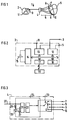
- the device 1 in FIG. 1 has a stimulation unit 2 in the form of a pacemaker which is connected, through a socket 3 over a switching device 4, to a heart 5 by an electrode system 6.
- the stimulation unit 2 could also have been a defibrillator or a cardioverter but, for the sake of simplicity, will only be described henceforth as a pacemaker 2.
- the electrode system 6 consists of a first tip electrode 7 and a second tip electrode 8 placed in the atrium of the heart 5, a third tip electrode 9 and a fourth tip electrode 10 placed in the ventricle of the heart 5.
- the pacemaker 2 is unipolarly coupled and has an indifferent electrode 11 on the exterior of the pacemaker 2 to conduct stimulation pulses back to the pacemaker from the electrode system 6.
- a stimulation pulse is generated by the pacemaker 2 and sent, along with a control signal, to the switching device 4.
- the control signal affects the switching device 4 in such a way that the stimulation pulse is sent to one of the tip electrodes 7 - 10 in the electrode system 6 and delivered to the heart 5.
- the stimulation pulse is then conducted over body tissue back to the indifferent electrode 11 and the pacemaker 2.
- FIG. 2 shows a block diagram of the pacemaker 2, containing a pulse generator 12 connected to the pulse signal output socket 3 and the indifferent electrode 11, and a measurement appliance 13 which is also connected to the pulse signal output socket 3 and the indifferent electrode 11.
- the pulse generator 12 generates the stimulation pulses.
- the measurement appliance 13 senses the heart's electrical activity after the switching device 4 closes a connection between the pacemaker 2 and the electrode system 6.
- a control device 14 controls, via a data bus 15, the pulse generator 12 and the measurement appliance 13. Stimulation pulses can be modulated with control signals in a modulator 16.
- the modulator 16 is also connected to the control device 14 via the data bus 15.
- a physician can program the control device 14 to perform various functions.
- the telemetry unit 17 is also connected to the data bus 15. Power for the pacemaker 2 is supplied by a battery 19.
- stimulation pulses with superimposed control signals are sent by the pulse generator 12 over the pulse signal output socket 3 to the switching device 4.
- the signals are sent via a signal input socket 20 to a signal discriminator 21 which demodulates the control signal and feeds it to a control appliance 22 for controlling a switch 23.
- the switch 23 has four output positions 23A - D connected to the first tip electrode 7, the second tip electrode 8, the third tip electrode 9 and the fourth tip electrode 10 respectively.
- a line 24 connects the switch 23 to the signal input socket 20 to transmit stimulation pulses across the switch 23 to the selected electrode tip.
- the switching device 4 also contains a diode 25 and a capacitor connected in parallel over the line 24 to drive the switching device 4.
- the diode 25 is connected to the signal input socket 20 and to the capacitor 26 which is connected in parallel across the switching device's 4 power supply input socket 27.
- An energy pulse whose polarity is opposite to the polarity of the stimulation pulses, is emitted to charge the capacitor 26 with the energy required to drive the switching device 4.
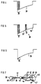
- FIG. 4 shows a first stimulation pulse 28 with a superimposed control signal 29.
- the stimulation pulse 28 is generated by the pulse generator 12 with an amplitude and duration controlled by the control device 14.
- the modulator 16 modulates the control signal 29 over the first part of the stimulation pulse 28.
- the stimulation pulse 28 is sent over the pulse signal output socket 3 to the switching device's 4 signal input socket 20.
- the control signal is demodulated in the signal discriminator and fed to the control appliance 22 which sends a switching signal to the switch 23.
- the control signal indicates that the switch 23 must enable output position 23A which is connected to the first tip electrode 7.
- the stimulation pulse 28 is sent from the signal input socket 20 over line 24 to switch 23 and out through output position 23A to the first tip electrode 7 which delivers the stimulation pulse 28 to the heart 5.
- the stimulation pulse 28 is then conducted through body tissue back to the indifferent electrode 11 and the pulse generator 12.
- FIG. 5 shows a second stimulation pulse 30 which contains a first control signal in the form of a pulse package 31, a first stimulation pulse part 32, a second control signal in the form of a pulse package 33 and a second stimulation pulse part 34.
- the first control signal 31 can e.g. cause transmission of the first stimulation pulse part 31 to the heart 5 over the third tip electrode 9, and the second control signal 33 sets the switch 23 in such a way that the second stimulation pulse part 34 is delivered to the heart 5 over the fourth tip electrode 10.
- FIG. 6 shows a third stimulation pulse 35 in which the control signal 36 consists of a high-frequency signal superimposed on the stimulation pulse 35.
- the device 37 comprises a pacemaker 38 for bipolar operation which is connected, over a pulse signal output socket 39 and a switching device 40, to a first measurement device 41, a second measurement device 42 and, through an electrode system 44, a heart 43.
- the pacemaker 38 has an indifferent electrode 49 on its case.
- the electrode system 44 consists of a first tip electrode 45 and a first ring electrode 46 placed in the atrium of the heart 43, and a second tip electrode 47 and a second ring electrode 48 placed in the ventricle of the heart 43.
- a stimulation pulse generated by the pacemaker 38 and a control signal are simultaneously emitted and act on the switch 40 to open a connection with e.g. the second tip electrode 47, which delivers the stimulation pulse to the heart 43, and the second ring electrode 48 over which he stimulation pulse is conducted back to the pacemaker 38.
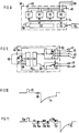
- the pacemaker 38 contains, like the pacemaker 2 in FIG. 2, a pulse generator 50, a measurement appliance 51, a control device 52 and a telemetry unit 53, all connected to each other via a data bus 54.
- the telemetry unit 53 transmits programming and information between the control device 52 and a programming unit 55.
- the pacemaker 38 also contains a control signal generator 56 and a power source 57, both connected to the pulse signal output socket 39.
- the pulse generator 50, the control signal generator 56 and the power source 57 are shown here as three separate units for the sake of clarity but could also consist of a single unit. All pacemaker electronic circuitry is supplied with power by the battery 58.
- the control device 52 controls the switching device 40 to connect the first measurement device 41 or the second measurement device 42 or any of the electrode system's 44 electrodes 45, 46, 47, 48 to the pulse signal output socket 39.
- the switching device 40 has a signal input socket 59 which is connected to the pulse signal output socket 39 and which conducts signals from the pulse signal output socket 39 to a signal discriminator 60 to separate the control signal and send it to a control appliance 61.
- the control appliance 61 controls a first switch 62 and a second switch 63.
- the first switch 61 has five output positions 62A - E, the first output position 62A connected to the first measurement device 41, the second output position 62B connected to the second measurement device 42, the third output position 62C connected to the first tip electrode 45 and the fourth output position 62D connected to the second tip electrode 47, the fifth output position 62E having no connection.
- the second switch 63 has three output positions 63A - C, the first output position 63A connected to the first ring electrode 46, the second output position 63B connected to the second ring electrode 48, the third output position 63C having no connection.
- a first line 64 connects the signal input socket 59 to the first switch 62, and a second line 65 connects the signal input socket 59 to the second switch 63.
- a diode 66 and a capacitor 67 are connected in parallel over the signal input socket 59, the capacitor 67 being charged from the pacemaker 38 in order to supply the switching device 40 with power through a power supply input socket 68.
- FIG. 10 shows an energy pulse 70, generated by the power source 57, to charge the capacitor 67.
- the switching device 40 is in its output mode, i.e. the first switch 62 is in its fifth position 62E and the second switch 63 is in its third position 63C.
- a control signal 69 follows the energy pulse 70 and causes the first switch 62 to be set at its third position 62C in order to send the stimulation pulse 71 to the first tip electrode 45 and set the second switch 63 to its first position 63A so as to conduct the stimulation pulse 71 back to the pulse generator 50 over the first ring electrode 46 and the switching device 40.
- the stimulation pulse 71 can also be emitted unipolarly, whereby the second switch 63 is set at its third output position 63C, and the connection between the indifferent electrode 49 and the pulse generator 50 is closed.
- FIG. 11 shows a first energy pulse 73a for charging the capacitor 67.
- a first control signal 72a closes the connection between the measurement appliance 51 and the first measurement device 41, a measurement signal 74a then being transmitted from the first measurement device 41 to the measurement appliance 51.
- a second control signal 72b sets the switch 62 in such a way that the connection to the second control device 42 is closed.
- the measurement appliance 57 emits a second energy pulse 73b followed by a measurement control signal 74b generated by the power source 57 in order to supply the second measurement device 42 with power and control same.
- the second measurement device 42 can have a capacitor which is charged by the second energy pulse 73b.
- a third control signal 72d causes the connection with the second tip electrode 47 and the second ring electrode 48 to close so a stimulation pulse 75 is delivered to the heart 43.
- the switches 23, 62, 63 in FIGS. 3 and 9 can be devised with e.g. transistors or in some other known manner.
- Power for the switching device 40 can also be provided in some way other than with a capacitor 67 which is charged, viz. by having the power source 57 emit a supply current sufficient to cover the switching device's 40 power needs.
Landscapes
- Health & Medical Sciences (AREA)
- Life Sciences & Earth Sciences (AREA)
- Cardiology (AREA)
- Heart & Thoracic Surgery (AREA)
- Public Health (AREA)
- Engineering & Computer Science (AREA)
- Biomedical Technology (AREA)
- Nuclear Medicine, Radiotherapy & Molecular Imaging (AREA)
- Radiology & Medical Imaging (AREA)
- Animal Behavior & Ethology (AREA)
- General Health & Medical Sciences (AREA)
- Veterinary Medicine (AREA)
- Physiology (AREA)
- Biophysics (AREA)
- Neurology (AREA)
- Neurosurgery (AREA)
- Electrotherapy Devices (AREA)
Abstract
Description
- The invention relates to a device for stimulating living tissue, comprising a stimulation unit which emits stimulation pulses over a pulse signal output socket, an electrode system which delivers the stimulation pulses to the living tissue, a controllable switching device through which the electrode system is connected to the pulse signal output socket to transmit the stimulation pulses to a specific part of the electrode system and a control device which emits control signals over a control output socket to a control input socket on the switching device to control transmission of stimulation pulses.
- One such device is prior art through US-A-4,628,934. The known device contains a pacemaker, a switching unit and an electrode system. The electrode system consists of two multipolar electrodes which can be unipolarly or bipolarly connected to the pacemaker via the switching unit. The switching unit is controllable and directly controlled from pacemaker electronic circuitry via control lines. With the aid of the switch, the required number of feedthroughs to pacemaker electronic circuitry, which is enclosed in a pacemaker case, can be reduced. In a unipolar version, one feedthrough is employed for delivering stimulation pulses from pacemaker electronic circuitry and control lines for controlling the switch. In a bipolar version, there are two feedthroughs, each with a line for delivering stimulation pulses, and control lines to the switching unit. In one version of the prior art device, a serial-to-parallel signal converter is employed in the switching unit to reduce to one the number of control lines to pacemaker electronic circuitry. A pulse train, which in the serial-to-parallel signal converter is applied in parallel to the switches in the switching unit, is then fed through this single control line. When the switching device is devised in the form of a detachable adapter for a pacemaker, two electrodes can be coupled, over the adapter, to a pacemaker designed for one electrode.
- The object of the invention is to produce a device as described above in which the number of feedthroughs is further reduced.
- The invention even intends to produce a device which can easily be adapted to a plurality of functions in e.g. the diagnosis or therapeutic treatment of living tissue.
- One such device is achieved in accordance with the invention in that the control device's control output socket in coupled to the pulse signal output socket, the switching device's control input socket is coupled to the pulse signal output socket and the switching device contains a signal discriminator to separate control signals from stimulation pulses so they control the switching device's transmission of the stimulation pulses.
- The number of feedthroughs is hereby minimized. For a unipolar device, one feedthrough is sufficient through which stimulation pulses and control signals are transmitted to the switching device and on to the electrode system. In the corresponding way, a bipolar device has two feedthroughs. The signal discriminator discriminates the different types of signals and separates them so the control signal can be used for controlling the switching device's setting. In e.g. a version with a pacemaker, a plurality of electrodes can be placed in a heart and connected to the pacemaker via the switching device. The heart's response to stimulation pulses at different locations in the heart can be easily studied so as to e.g. ascertain the best site for a permanently implanted electrode.
- One way of discriminating stimulation pulses and control signals is achieved in accordance with the invention in that control signals and stimulation pulses have different polarities, and the signal discriminator senses polarity in order to distinguish control signals from stimulation pulses.
- The different polarities make it easy to distinguish between the types of signal. Irrespective of whether the same or different polarities are used for the signals, it is advantageous for the control signals to have an amplitude lower than the threshold value required to stimulate the living tissue, since there would then be no risk of erroneous tissue stimulation caused by control signals sent to the electrode system.
- Alternately, the signals can be discriminated when the control device contains a modulator to modulate the stimulation pulses with the control signals, and the signal discriminator contains a demodulator to separate control signals from stimulation pulses.
- An improvement of the device is achieved in accordance with the invention in that at least one measurement device is coupled, over the switching device, to the pulse signal output socket, whereby the control device, by means of a control signal, closes a signal connection between the measurement device and a measurement appliance in the stimulation unit.
- As a result, the device can be expanded into a multifunctional unit capable of stimulating tissue and measuring physiological variables in stimulated or other tissue. The measured variables can be used by the stimulation unit for enhanced monitoring and control of tissue stimulation. Physiological variables which can be measured are e.g. temperature, blood oxygen, tissue impedance and movements. When the control signal closes the connection between the stimulation unit and the measurement device, the measurement signal is sent from the measurement device to the measurement appliance.
- In this context, it is advantageous for the measurement device to be controllable, for the control device to emit measurement control signals and for the signal discriminator to be devised to distinguish between control signals and measurement control signals so control signals control the switching device's transmission of measurement control signals to the measurement device.
- The stimulation unit then provides complete control over all functional units in the device. The control signals open different connections between the stimulation unit and the electrode system or the measurement device over the switching device. The stimulation unit can control the measurement device's measurement of the physiological variable and receive the measurement signals from the measurement device in order to vary stimulation of the living tissue on the basis thereof.
- Another improvement of the device is achieved in accordance with the invention in that the switching device contains a power supply input socket connected to the pulse signal output socket, and the stimulation unit contains a power source which delivers power to the power supply input socket.
- In this way, the switching device's power needs are wholly covered by the stimulation unit. Here, power can be transmitted as a supply current to the power supply input socket in the switching device, or the switching device can contain a capacitor connected to the power supply input socket through which the power source charges the capacitor.
- One advantage in this context is that the power source is connected to the measurement device over the switching device, and the power source supplies current for the measurement device's power needs when the connection between the power source and the measurement device is closed.
- Embodiments of the invention will be described below referring to the figures, whereby
- FIG. 1 shows a first embodiment of the device in accordance with the invention;
- FIG. 2 shows a block diagram of the stimulation unit in the device;
- FIG. 3 shows a block diagram of the switching device in the device;
- FIGS. 4 - 6 illustrate three different ways of sending a control signal and a stimulation pulse from the stimulation unit to the switching device;
- FIG. 7 shows a second embodiment of the device in accordance with the invention;
- FIG. 8 shows a block diagram of the stimulation unit in the device according to FIG. 7;
- FIG. 9 shows a block diagram of the switching device in the device in FIG. 7;
- FIGS. 10 - 11 illustrate two different ways of sending a plurality of different signals from the stimulation unit to the switching device in the device in FIG. 7.
- The device 1 in FIG. 1 has a stimulation unit 2 in the form of a pacemaker which is connected, through a socket 3 over a switching device 4, to a
heart 5 by anelectrode system 6. The stimulation unit 2 could also have been a defibrillator or a cardioverter but, for the sake of simplicity, will only be described henceforth as a pacemaker 2. Theelectrode system 6 consists of afirst tip electrode 7 and asecond tip electrode 8 placed in the atrium of theheart 5, athird tip electrode 9 and afourth tip electrode 10 placed in the ventricle of theheart 5. The pacemaker 2 is unipolarly coupled and has anindifferent electrode 11 on the exterior of the pacemaker 2 to conduct stimulation pulses back to the pacemaker from theelectrode system 6. A stimulation pulse is generated by the pacemaker 2 and sent, along with a control signal, to the switching device 4. The control signal affects the switching device 4 in such a way that the stimulation pulse is sent to one of the tip electrodes 7 - 10 in theelectrode system 6 and delivered to theheart 5. The stimulation pulse is then conducted over body tissue back to theindifferent electrode 11 and the pacemaker 2. - FIG. 2 shows a block diagram of the pacemaker 2, containing a
pulse generator 12 connected to the pulse signal output socket 3 and theindifferent electrode 11, and ameasurement appliance 13 which is also connected to the pulse signal output socket 3 and theindifferent electrode 11. Thepulse generator 12 generates the stimulation pulses. Themeasurement appliance 13 senses the heart's electrical activity after the switching device 4 closes a connection between the pacemaker 2 and theelectrode system 6. Acontrol device 14 controls, via adata bus 15, thepulse generator 12 and themeasurement appliance 13. Stimulation pulses can be modulated with control signals in amodulator 16. Themodulator 16 is also connected to thecontrol device 14 via thedata bus 15. Using atelemetry unit 17 and anextracorporeal programing unit 18, a physician can program thecontrol device 14 to perform various functions. Thetelemetry unit 17 is also connected to thedata bus 15. Power for the pacemaker 2 is supplied by a battery 19. - Thus, stimulation pulses with superimposed control signals are sent by the
pulse generator 12 over the pulse signal output socket 3 to the switching device 4. In the switching device 4, as shown in FIG. 3, the signals are sent via a signal input socket 20 to asignal discriminator 21 which demodulates the control signal and feeds it to a control appliance 22 for controlling aswitch 23. Theswitch 23 has four output positions 23A - D connected to thefirst tip electrode 7, thesecond tip electrode 8, thethird tip electrode 9 and thefourth tip electrode 10 respectively. Aline 24 connects theswitch 23 to the signal input socket 20 to transmit stimulation pulses across theswitch 23 to the selected electrode tip. The switching device 4 also contains a diode 25 and a capacitor connected in parallel over theline 24 to drive the switching device 4. The diode 25 is connected to the signal input socket 20 and to the capacitor 26 which is connected in parallel across the switching device's 4 powersupply input socket 27. An energy pulse, whose polarity is opposite to the polarity of the stimulation pulses, is emitted to charge the capacitor 26 with the energy required to drive the switching device 4. - Referring to FIGS. 4 - 6, three examples of stimulation pulses which can be used in the device according to FIGS. 1 - 3 will be described below. FIG. 4 shows a
first stimulation pulse 28 with a superimposed control signal 29. Thestimulation pulse 28 is generated by thepulse generator 12 with an amplitude and duration controlled by thecontrol device 14. Themodulator 16 modulates the control signal 29 over the first part of thestimulation pulse 28. Thestimulation pulse 28 is sent over the pulse signal output socket 3 to the switching device's 4 signal input socket 20. The control signal is demodulated in the signal discriminator and fed to the control appliance 22 which sends a switching signal to theswitch 23. For example, if the pacemaker is to deliver a stimulation pulse to the atrium of theheart 5 over thefirst tip electrode 7, the control signal indicates that theswitch 23 must enable output position 23A which is connected to thefirst tip electrode 7. Here, thestimulation pulse 28 is sent from the signal input socket 20 overline 24 to switch 23 and out through output position 23A to thefirst tip electrode 7 which delivers thestimulation pulse 28 to theheart 5. Thestimulation pulse 28 is then conducted through body tissue back to theindifferent electrode 11 and thepulse generator 12. - FIG. 5 shows a
second stimulation pulse 30 which contains a first control signal in the form of a pulse package 31, a firststimulation pulse part 32, a second control signal in the form of a pulse package 33 and a secondstimulation pulse part 34. The first control signal 31 can e.g. cause transmission of the first stimulation pulse part 31 to theheart 5 over thethird tip electrode 9, and the second control signal 33 sets theswitch 23 in such a way that the secondstimulation pulse part 34 is delivered to theheart 5 over thefourth tip electrode 10. - FIG. 6 shows a
third stimulation pulse 35 in which the control signal 36 consists of a high-frequency signal superimposed on thestimulation pulse 35. - A second embodiment of the device according to the invention is shown in FIG. 7. The
device 37 comprises apacemaker 38 for bipolar operation which is connected, over a pulsesignal output socket 39 and aswitching device 40, to a first measurement device 41, asecond measurement device 42 and, through an electrode system 44, a heart 43. For unipolar operation, thepacemaker 38 has anindifferent electrode 49 on its case. The electrode system 44 consists of afirst tip electrode 45 and afirst ring electrode 46 placed in the atrium of the heart 43, and asecond tip electrode 47 and asecond ring electrode 48 placed in the ventricle of the heart 43. A stimulation pulse generated by thepacemaker 38 and a control signal are simultaneously emitted and act on theswitch 40 to open a connection with e.g. thesecond tip electrode 47, which delivers the stimulation pulse to the heart 43, and thesecond ring electrode 48 over which he stimulation pulse is conducted back to thepacemaker 38. - As FIG. 8 shows, the
pacemaker 38 contains, like the pacemaker 2 in FIG. 2, apulse generator 50, ameasurement appliance 51, acontrol device 52 and atelemetry unit 53, all connected to each other via adata bus 54. Thetelemetry unit 53 transmits programming and information between thecontrol device 52 and aprogramming unit 55. Thepacemaker 38 also contains acontrol signal generator 56 and apower source 57, both connected to the pulsesignal output socket 39. Thepulse generator 50, thecontrol signal generator 56 and thepower source 57 are shown here as three separate units for the sake of clarity but could also consist of a single unit. All pacemaker electronic circuitry is supplied with power by thebattery 58. With thecontrol signal generator 56, thecontrol device 52 controls theswitching device 40 to connect the first measurement device 41 or thesecond measurement device 42 or any of the electrode system's 44electrodes signal output socket 39. - As shown in FIG. 9, the switching
device 40 has asignal input socket 59 which is connected to the pulsesignal output socket 39 and which conducts signals from the pulsesignal output socket 39 to a signal discriminator 60 to separate the control signal and send it to a control appliance 61. The control appliance 61 controls afirst switch 62 and asecond switch 63. The first switch 61 has five output positions 62A - E, the first output position 62A connected to the first measurement device 41, the second output position 62B connected to thesecond measurement device 42, the third output position 62C connected to thefirst tip electrode 45 and the fourth output position 62D connected to thesecond tip electrode 47, the fifth output position 62E having no connection. Thesecond switch 63 has three output positions 63A - C, the first output position 63A connected to thefirst ring electrode 46, the second output position 63B connected to thesecond ring electrode 48, the third output position 63C having no connection. A first line 64 connects thesignal input socket 59 to thefirst switch 62, and a second line 65 connects thesignal input socket 59 to thesecond switch 63. - A
diode 66 and a capacitor 67 are connected in parallel over thesignal input socket 59, the capacitor 67 being charged from thepacemaker 38 in order to supply theswitching device 40 with power through a power supply input socket 68. - Referring to FIGS. 10 and 11, two examples of signal transmission which can be used in the
device 37 according to FIG. 7 - 9 will be described below. FIG. 10 shows an energy pulse 70, generated by thepower source 57, to charge the capacitor 67. Here, the switchingdevice 40 is in its output mode, i.e. thefirst switch 62 is in its fifth position 62E and thesecond switch 63 is in its third position 63C. A control signal 69 follows the energy pulse 70 and causes thefirst switch 62 to be set at its third position 62C in order to send thestimulation pulse 71 to thefirst tip electrode 45 and set thesecond switch 63 to its first position 63A so as to conduct thestimulation pulse 71 back to thepulse generator 50 over thefirst ring electrode 46 and theswitching device 40. Thestimulation pulse 71 can also be emitted unipolarly, whereby thesecond switch 63 is set at its third output position 63C, and the connection between theindifferent electrode 49 and thepulse generator 50 is closed. - FIG. 11 shows a
first energy pulse 73a for charging the capacitor 67. Afirst control signal 72a closes the connection between themeasurement appliance 51 and the first measurement device 41, ameasurement signal 74a then being transmitted from the first measurement device 41 to themeasurement appliance 51. Asecond control signal 72b sets theswitch 62 in such a way that the connection to thesecond control device 42 is closed. Here, themeasurement appliance 57 emits asecond energy pulse 73b followed by ameasurement control signal 74b generated by thepower source 57 in order to supply thesecond measurement device 42 with power and control same. Here thesecond measurement device 42 can have a capacitor which is charged by thesecond energy pulse 73b. A third control signal 72d causes the connection with thesecond tip electrode 47 and thesecond ring electrode 48 to close so astimulation pulse 75 is delivered to the heart 43. - The
switches switching device 40 can also be provided in some way other than with a capacitor 67 which is charged, viz. by having thepower source 57 emit a supply current sufficient to cover the switching device's 40 power needs.
Claims (10)
- A device (1; 37) for stimulating living tissue (5; 43) comprising a stimulation unit (2; 38) which emits stimulation pulses over a pulse signal output socket (3; 39), an electrode system (6; 44) which delivers the stimulation pulses to the living tissue (5; 43), a controllable switching device (4; 40) through which the electrode system (6; 44) is connected to the pulse signal output socket (3; 39) to transmit the stimulation pulses to a specific part of the electrode system (6; 44) and a control device (12, 14, 16; 52, 56) which emits control signals over a control output socket to a control input socket (20; 59) on the switching device (4; 40) to control transmission of the stimulation pulses, characterized in that the control device's (12, 14, 16; 52, 56) control output socket is connected to the pulse signal output socket (3; 39), the switching device's (4; 40) control input socket (20; 59) is connected to the pulse signal output socket (3; 39), and the switching device (4; 40) contains a signal discriminator (21; 60) to separate control signals from stimulation pulses so the control signals control the switching device's (4; 40) transmission of stimulation pulses.
- A device of claim 1, wherein control signals and stimulation pulses have different polarities, and the signal discriminator (21; 60) senses polarity in order to distinguish control signals from stimulation pulses.
- A device of claim 1 or 2, wherein, control signals have a lower amplitude than the threshold value required to stimulate the living tissue (5; 43).
- A device of claim 1, wherein the control device (12, 14, 16; 52, 56) contains a modulator (16; 56) to modulate the stimulation pulses with the control signals, and the signal discriminator (21; 60) contains a demodulator to separate control signals from stimulation pulses.
- A device of any of the above claims, wherein at least one measurement device (41; 42) is coupled, over the switching device (40), to the pulse signal output socket (39), whereby the control device (52, 56), by means of a control signal, closes a signal connection between the measurement device (41, 42) and a measurement appliance (51) in the stimulation unit (38).
- A device of claim 5, wherein the measurement device (41; 42) is controllable, the control device (52, 56) emits measurement control signals and the signal discriminator (60) is devised to distinguish between control signals and measurement control signals so control signals control the switching device's (40) transmission of measurement control signals to the measurement device (41, 42).
- A device of any of the above claims, wherein the switching device (4; 40) contains a power supply input socket (27; 68) connected to the pulse signal output socket (3; 39), and the stimulation unit (2; 38) contains a power source (57) which delivers power to the power supply input socket (27; 68).
- A device of claim 7, wherein the power source (57) supplies supply current to the power supply input socket (27; 68).
- A device of claim 7, wherein the switching device (4; 40) contains a capacitor (26; 67) connected to the power supply input socket (27; 68) through which the power source (57) charges the capacitor (26; 67).
- A device of any of claims 7 - 9 in combination with claim 5 or 6, wherein, the power source (57) is connected to the measurement device (41; 42) over the switching device (40), and the power source (57) supplies current for the measurement device's (41; 42) power needs when the connection between the power source (57) and the measurement device (41; 42) is closed.
Applications Claiming Priority (2)
| Application Number | Priority Date | Filing Date | Title |
|---|---|---|---|
| SE9202521A SE9202521D0 (en) | 1992-09-02 | 1992-09-02 | DEVICE FOR STIMULATION OF LIVING WEAVEN |
| SE9202521 | 1992-09-02 |
Publications (2)
| Publication Number | Publication Date |
|---|---|
| EP0585582A1 true EP0585582A1 (en) | 1994-03-09 |
| EP0585582B1 EP0585582B1 (en) | 1998-03-11 |
Family
ID=20387073
Family Applications (1)
| Application Number | Title | Priority Date | Filing Date |
|---|---|---|---|
| EP93111476A Expired - Lifetime EP0585582B1 (en) | 1992-09-02 | 1993-07-16 | Device for stimulating living tissue |
Country Status (5)
| Country | Link |
|---|---|
| US (2) | US5423873A (en) |
| EP (1) | EP0585582B1 (en) |
| JP (1) | JPH06154344A (en) |
| DE (1) | DE69317338T2 (en) |
| SE (1) | SE9202521D0 (en) |
Cited By (3)
| Publication number | Priority date | Publication date | Assignee | Title |
|---|---|---|---|---|
| EP0598617A2 (en) * | 1992-11-19 | 1994-05-25 | Pacesetter, Inc. | Electrically programmable polarity connector for an implantable body tissue stimulator |
| WO1999043381A1 (en) * | 1998-02-25 | 1999-09-02 | Pacesetter Ab | Implantable lead with switching means for switching between sensing and stimulating and medical device with such a lead |
| EP1249254A3 (en) * | 2001-04-12 | 2004-03-24 | Pacesetter, Inc. | System and method for automatically selecting electrode polarity during sensing and stimulation |
Families Citing this family (49)
| Publication number | Priority date | Publication date | Assignee | Title |
|---|---|---|---|---|
| FR2796562B1 (en) | 1996-04-04 | 2005-06-24 | Medtronic Inc | TECHNIQUES FOR STIMULATING LIVING TISSUE AND RECORDING WITH LOCAL CONTROL OF ACTIVE SITES |
| EP0892654B1 (en) * | 1996-04-04 | 2003-06-11 | Medtronic, Inc. | Apparatus for living tissue stimulation and recording techniques |
| US5800465A (en) * | 1996-06-18 | 1998-09-01 | Medtronic, Inc. | System and method for multisite steering of cardiac stimuli |
| SE9602846D0 (en) * | 1996-07-23 | 1996-07-23 | Pacesetter Ab | A stimulation device |
| US5987354A (en) * | 1996-08-13 | 1999-11-16 | Uab Research Foundation | Dual shock atrial defibrillation apparatus |
| US6006131A (en) * | 1996-08-13 | 1999-12-21 | Uab Research Foundation | Dual current pathway atrial defibrillation apparatus |
| US5999848A (en) * | 1997-09-12 | 1999-12-07 | Alfred E. Mann Foundation | Daisy chainable sensors and stimulators for implantation in living tissue |
| US6259937B1 (en) * | 1997-09-12 | 2001-07-10 | Alfred E. Mann Foundation | Implantable substrate sensor |
| US5999853A (en) * | 1998-03-02 | 1999-12-07 | Vitatron Medical, B.V. | Dual chamber pacemaker with single pass lead and with bipolar and unipolar signal processing capability |
| DE19930265A1 (en) * | 1999-06-25 | 2000-12-28 | Biotronik Mess & Therapieg | Electrode arrangement |
| DE19930271A1 (en) * | 1999-06-25 | 2000-12-28 | Biotronik Mess & Therapieg | Electrode arrangement |
| WO2001074278A2 (en) * | 2000-03-31 | 2001-10-11 | Advanced Bionics Corporation | High contact count, sub-miniature fully implantable cochlear prosthesis |
| US6484057B2 (en) | 2000-12-21 | 2002-11-19 | Uab Research Foundation | Pacing methods and devices for treating cardiac arrhythmias and fibrillation |
| US7130682B2 (en) * | 2000-12-26 | 2006-10-31 | Cardiac Pacemakers, Inc. | Pacing and sensing vectors |
| US7010350B2 (en) * | 2001-03-21 | 2006-03-07 | Kralik Michael R | Temporary biventricular pacing of heart after heart surgery |
| US6477417B1 (en) | 2001-04-12 | 2002-11-05 | Pacesetter, Inc. | System and method for automatically selecting electrode polarity during sensing and stimulation |
| US6687542B2 (en) | 2001-10-03 | 2004-02-03 | Pacesetter, Inc. | XY selectable lead assembly |
| US7286878B2 (en) * | 2001-11-09 | 2007-10-23 | Medtronic, Inc. | Multiplexed electrode array extension |
| US20030149456A1 (en) * | 2002-02-01 | 2003-08-07 | Rottenberg William B. | Multi-electrode cardiac lead adapter with multiplexer |
| US7110815B2 (en) * | 2002-05-06 | 2006-09-19 | Cardiac Pacemakers, Inc. | System and method for providing temporary stimulation therapy to optimize chronic electrical performance for electrodes used in conjunction with a cardiac rhythm management system |
| US7139608B2 (en) * | 2002-07-31 | 2006-11-21 | Uab Research Foundation | Pacing methods and devices using feedback controlled timing |
| US20040049118A1 (en) * | 2002-09-10 | 2004-03-11 | Ideker Raymond E. | Methods, systems and computer program products for treating fibrillation in a patient based on the presence of fibrillation following administration of defibrillation therapy |
| US8560063B2 (en) * | 2002-09-10 | 2013-10-15 | Uab Research Foundation | Post-defibrillation pacing methods and devices |
| US7162298B2 (en) * | 2002-09-10 | 2007-01-09 | Uab Research Foundation | Devices for detecting the presence of cardiac activity following administration of defibrillation therapy |
| US7522958B2 (en) * | 2003-03-13 | 2009-04-21 | Uab Research Foundation | Methods and systems for reducing discomfort from cardiac defibrillation shocks |
| US7254443B2 (en) * | 2003-06-06 | 2007-08-07 | Medtronic, Inc. | Implantable medical device including a hermetic connector block extension |
| US8019420B2 (en) * | 2003-08-21 | 2011-09-13 | Medtronic, Inc. | Medical lead connector systems with adapters |
| US8065008B2 (en) * | 2003-08-21 | 2011-11-22 | Medtronic, Inc. | Multi-polar electrical medical lead connector system |
| US8489196B2 (en) * | 2003-10-03 | 2013-07-16 | Medtronic, Inc. | System, apparatus and method for interacting with a targeted tissue of a patient |
| US20050107833A1 (en) * | 2003-11-13 | 2005-05-19 | Freeman Gary A. | Multi-path transthoracic defibrillation and cardioversion |
| US7734344B2 (en) | 2003-12-02 | 2010-06-08 | Uab Research Foundation | Methods, systems and computer program products to inhibit ventricular fibrillation during cardiopulmonary resuscitation |
| US7236834B2 (en) * | 2003-12-19 | 2007-06-26 | Medtronic, Inc. | Electrical lead body including an in-line hermetic electronic package and implantable medical device using the same |
| US20050165456A1 (en) * | 2003-12-19 | 2005-07-28 | Brian Mann | Digital electrode for cardiac rhythm management |
| US20050148980A1 (en) * | 2003-12-30 | 2005-07-07 | Kimberly-Clark Worldwide, Inc. | Absorbent garment having outer shell and discreet absorbent assembly adapted for positioning therein |
| US7286884B2 (en) | 2004-01-16 | 2007-10-23 | Medtronic, Inc. | Implantable lead including sensor |
| US20060030906A1 (en) * | 2004-08-06 | 2006-02-09 | Carroll William J | Switchable and programmable electrode configuration |
| US20060149330A1 (en) * | 2004-12-30 | 2006-07-06 | Brian Mann | Digitally controlled cardiac rhythm management |
| US7711419B2 (en) | 2005-07-13 | 2010-05-04 | Cyberonics, Inc. | Neurostimulator with reduced size |
| US7489561B2 (en) | 2005-10-24 | 2009-02-10 | Cyberonics, Inc. | Implantable medical device with reconfigurable non-volatile program |
| FR2910818A1 (en) * | 2006-12-28 | 2008-07-04 | Ela Medical Soc Par Actions Si | MULTIPLEXED ELECTRODE CONTROLLED SWITCHING CIRCUIT FOR ACTIVE ACTIVE IMPLANTABLE DISPOSITION |
| WO2008105691A1 (en) * | 2007-02-28 | 2008-09-04 | St. Jude Medical Ab | Device and method for detecting a myocardial infarction and treating the myocardial infarction using therapeutic light |
| US8649858B2 (en) * | 2007-06-25 | 2014-02-11 | Boston Scientific Neuromodulation Corporation | Architectures for an implantable medical device system |
| JP2010540073A (en) * | 2007-09-27 | 2010-12-24 | カーディアック ペースメイカーズ, インコーポレイテッド | Embedded lead wire with electrical stimulation capacitor |
| DE102007061483A1 (en) * | 2007-12-20 | 2009-07-02 | Erbe Elektromedizin Gmbh | Surgery Equipment connector system |
| WO2011065881A1 (en) | 2009-11-30 | 2011-06-03 | St. Jude Medical Ab | A medical implantable lead with fixation detection |
| US8396563B2 (en) | 2010-01-29 | 2013-03-12 | Medtronic, Inc. | Clock synchronization in an implantable medical device system |
| US8874233B2 (en) | 2013-03-05 | 2014-10-28 | The Charles Stark Draper Laboratory, Inc. | Distributed neuro-modulation system with auxiliary stimulation-recording control units |
| US10004904B2 (en) | 2013-03-07 | 2018-06-26 | Imthera Medical, Inc | Lead splitter for neurostimulation systems |
| US20150018913A1 (en) * | 2013-07-11 | 2015-01-15 | Boston Scientific Neuromodulation Corporation | Leads, systems, and methods for neuromodulation using superposition signals |
Citations (3)
| Publication number | Priority date | Publication date | Assignee | Title |
|---|---|---|---|---|
| US4579119A (en) * | 1983-11-18 | 1986-04-01 | Cordis Corporation | Method and apparatus for multiplexed dipole/quadrupole for stimulation/sensing |
| US4628934A (en) * | 1984-08-07 | 1986-12-16 | Cordis Corporation | Method and means of electrode selection for pacemaker with multielectrode leads |
| US4877032A (en) * | 1986-06-16 | 1989-10-31 | Siemens Aktiengesellschaft | Sensor arrangement for the control of implantable devices |
Family Cites Families (4)
| Publication number | Priority date | Publication date | Assignee | Title |
|---|---|---|---|---|
| US3727616A (en) * | 1971-06-15 | 1973-04-17 | Gen Dynamics Corp | Electronic system for the stimulation of biological systems |
| US4289134A (en) * | 1979-07-23 | 1981-09-15 | Electro-Catheter Corporation | Tripolar catheter apparatus |
| US4459989A (en) * | 1981-06-30 | 1984-07-17 | Neuromed, Inc. | Non-invasive multiprogrammable tissue stimulator and methods for use |
| US4989602A (en) * | 1989-04-12 | 1991-02-05 | Siemens-Pacesetter, Inc. | Programmable automatic implantable cardioverter/defibrillator and pacemaker system |
-
1992
- 1992-09-02 SE SE9202521A patent/SE9202521D0/en unknown
-
1993
- 1993-07-16 DE DE69317338T patent/DE69317338T2/en not_active Expired - Fee Related
- 1993-07-16 EP EP93111476A patent/EP0585582B1/en not_active Expired - Lifetime
- 1993-08-24 US US08/111,198 patent/US5423873A/en not_active Expired - Lifetime
- 1993-08-31 JP JP5215809A patent/JPH06154344A/en active Pending
-
1995
- 1995-01-12 US US08/371,824 patent/US5470348A/en not_active Expired - Lifetime
Patent Citations (3)
| Publication number | Priority date | Publication date | Assignee | Title |
|---|---|---|---|---|
| US4579119A (en) * | 1983-11-18 | 1986-04-01 | Cordis Corporation | Method and apparatus for multiplexed dipole/quadrupole for stimulation/sensing |
| US4628934A (en) * | 1984-08-07 | 1986-12-16 | Cordis Corporation | Method and means of electrode selection for pacemaker with multielectrode leads |
| US4877032A (en) * | 1986-06-16 | 1989-10-31 | Siemens Aktiengesellschaft | Sensor arrangement for the control of implantable devices |
Cited By (4)
| Publication number | Priority date | Publication date | Assignee | Title |
|---|---|---|---|---|
| EP0598617A2 (en) * | 1992-11-19 | 1994-05-25 | Pacesetter, Inc. | Electrically programmable polarity connector for an implantable body tissue stimulator |
| EP0598617A3 (en) * | 1992-11-19 | 1998-03-11 | Pacesetter, Inc. | Electrically programmable polarity connector for an implantable body tissue stimulator |
| WO1999043381A1 (en) * | 1998-02-25 | 1999-09-02 | Pacesetter Ab | Implantable lead with switching means for switching between sensing and stimulating and medical device with such a lead |
| EP1249254A3 (en) * | 2001-04-12 | 2004-03-24 | Pacesetter, Inc. | System and method for automatically selecting electrode polarity during sensing and stimulation |
Also Published As
| Publication number | Publication date |
|---|---|
| US5423873A (en) | 1995-06-13 |
| US5470348A (en) | 1995-11-28 |
| EP0585582B1 (en) | 1998-03-11 |
| DE69317338T2 (en) | 1998-07-16 |
| JPH06154344A (en) | 1994-06-03 |
| SE9202521D0 (en) | 1992-09-02 |
| DE69317338D1 (en) | 1998-04-16 |
Similar Documents
| Publication | Publication Date | Title |
|---|---|---|
| EP0585582B1 (en) | Device for stimulating living tissue | |
| US8005551B2 (en) | Implantable medical lead | |
| US5354320A (en) | Neurostimulator for production of periodic stimulation pulses | |
| US6381496B1 (en) | Parameter context switching for an implanted device | |
| US4543955A (en) | System for controlling body implantable action device | |
| US6600952B1 (en) | Secure telemetry system and method for an implantable cardiac stimulation device | |
| US5534018A (en) | Automatic lead recognition for implantable medical device | |
| EP0362611B1 (en) | Body bus medical device communication system | |
| US6757563B2 (en) | Cardiac rhythm management system with ultrasound for autocapture or other applications | |
| US5814089A (en) | Leadless multisite implantable stimulus and diagnostic system | |
| US7203551B2 (en) | Implantable lead-based sensor powered by piezoelectric transformer | |
| US4987897A (en) | Body bus medical device communication system | |
| EP2764891B1 (en) | Implantable stimulation device, stimulation system and method for data communication | |
| JP4149004B2 (en) | Implantable device system for monitoring and / or acting on body parameters | |
| EP0072611B1 (en) | Partially implanted multiprogrammable electronic tissue stimulator | |
| US8352025B2 (en) | Leadless cardiac pacemaker triggered by conductive communication | |
| US4705043A (en) | Electrophysiology study system using implantable cardioverter/pacer | |
| US5454837A (en) | Implantable medical system with optical communication between a treatment site and a therapy-generating apparatus | |
| US6907291B1 (en) | Secure telemetry system and method for an implantable cardiac stimulation device | |
| WO2001039831A1 (en) | Implantable device programmer | |
| US20090192572A1 (en) | Bidirectional Communications Between A Generator And Sensors Or Actuators Of A Lead For An Active Implantable Medical Device | |
| US5413593A (en) | Using sub-threshold unipolar pacing markers to improve the interpretation of surface EKG in pacemaker patients | |
| US20100066500A1 (en) | Selection of an imd by means of directional antenna | |
| US11071867B2 (en) | Capacitor-discharge communication scheme for an implantable medical system | |
| Lewis et al. | Early clinical experience with the rechargeable cardiac pacemaker |
Legal Events
| Date | Code | Title | Description |
|---|---|---|---|
| PUAI | Public reference made under article 153(3) epc to a published international application that has entered the european phase |
Free format text: ORIGINAL CODE: 0009012 |
|
| AK | Designated contracting states |
Kind code of ref document: A1 Designated state(s): DE FR GB IT NL SE |
|
| 17P | Request for examination filed |
Effective date: 19940620 |
|
| RAP1 | Party data changed (applicant data changed or rights of an application transferred) |
Owner name: PACESETTER AB |
|
| 17Q | First examination report despatched |
Effective date: 19960709 |
|
| GRAG | Despatch of communication of intention to grant |
Free format text: ORIGINAL CODE: EPIDOS AGRA |
|
| GRAG | Despatch of communication of intention to grant |
Free format text: ORIGINAL CODE: EPIDOS AGRA |
|
| GRAH | Despatch of communication of intention to grant a patent |
Free format text: ORIGINAL CODE: EPIDOS IGRA |
|
| GRAH | Despatch of communication of intention to grant a patent |
Free format text: ORIGINAL CODE: EPIDOS IGRA |
|
| GRAA | (expected) grant |
Free format text: ORIGINAL CODE: 0009210 |
|
| AK | Designated contracting states |
Kind code of ref document: B1 Designated state(s): DE FR GB IT NL SE |
|
| REF | Corresponds to: |
Ref document number: 69317338 Country of ref document: DE Date of ref document: 19980416 |
|
| ET | Fr: translation filed | ||
| PGFP | Annual fee paid to national office [announced via postgrant information from national office to epo] |
Ref country code: GB Payment date: 19980417 Year of fee payment: 6 |
|
| ITF | It: translation for a ep patent filed |
Owner name: STUDIO JAUMANN P. & C. S.N.C. |
|
| PG25 | Lapsed in a contracting state [announced via postgrant information from national office to epo] |
Ref country code: SE Free format text: LAPSE BECAUSE OF FAILURE TO SUBMIT A TRANSLATION OF THE DESCRIPTION OR TO PAY THE FEE WITHIN THE PRESCRIBED TIME-LIMIT Effective date: 19980611 |
|
| PLBE | No opposition filed within time limit |
Free format text: ORIGINAL CODE: 0009261 |
|
| STAA | Information on the status of an ep patent application or granted ep patent |
Free format text: STATUS: NO OPPOSITION FILED WITHIN TIME LIMIT |
|
| 26N | No opposition filed | ||
| PG25 | Lapsed in a contracting state [announced via postgrant information from national office to epo] |
Ref country code: GB Free format text: LAPSE BECAUSE OF NON-PAYMENT OF DUE FEES Effective date: 19990716 |
|
| PGFP | Annual fee paid to national office [announced via postgrant information from national office to epo] |
Ref country code: NL Payment date: 19990730 Year of fee payment: 7 |
|
| GBPC | Gb: european patent ceased through non-payment of renewal fee |
Effective date: 19990716 |
|
| PG25 | Lapsed in a contracting state [announced via postgrant information from national office to epo] |
Ref country code: NL Free format text: LAPSE BECAUSE OF NON-PAYMENT OF DUE FEES Effective date: 20010201 |
|
| NLV4 | Nl: lapsed or anulled due to non-payment of the annual fee |
Effective date: 20010201 |
|
| PGFP | Annual fee paid to national office [announced via postgrant information from national office to epo] |
Ref country code: FR Payment date: 20050630 Year of fee payment: 13 |
|
| REG | Reference to a national code |
Ref country code: FR Ref legal event code: ST Effective date: 20070330 |
|
| PG25 | Lapsed in a contracting state [announced via postgrant information from national office to epo] |
Ref country code: FR Free format text: LAPSE BECAUSE OF NON-PAYMENT OF DUE FEES Effective date: 20060731 |
|
| PGFP | Annual fee paid to national office [announced via postgrant information from national office to epo] |
Ref country code: DE Payment date: 20090728 Year of fee payment: 17 |
|
| PGFP | Annual fee paid to national office [announced via postgrant information from national office to epo] |
Ref country code: IT Payment date: 20090722 Year of fee payment: 17 |
|
| PG25 | Lapsed in a contracting state [announced via postgrant information from national office to epo] |
Ref country code: DE Free format text: LAPSE BECAUSE OF NON-PAYMENT OF DUE FEES Effective date: 20110201 |
|
| REG | Reference to a national code |
Ref country code: DE Ref legal event code: R119 Ref document number: 69317338 Country of ref document: DE Effective date: 20110201 |
|
| PG25 | Lapsed in a contracting state [announced via postgrant information from national office to epo] |
Ref country code: IT Free format text: LAPSE BECAUSE OF NON-PAYMENT OF DUE FEES Effective date: 20100716 |