EP0585030A1 - Infrared link between a transceiver and an external device - Google Patents
Infrared link between a transceiver and an external device Download PDFInfo
- Publication number
- EP0585030A1 EP0585030A1 EP93306456A EP93306456A EP0585030A1 EP 0585030 A1 EP0585030 A1 EP 0585030A1 EP 93306456 A EP93306456 A EP 93306456A EP 93306456 A EP93306456 A EP 93306456A EP 0585030 A1 EP0585030 A1 EP 0585030A1
- Authority
- EP
- European Patent Office
- Prior art keywords
- infrared
- speech
- transmitted
- external device
- data
- Prior art date
- Legal status (The legal status is an assumption and is not a legal conclusion. Google has not performed a legal analysis and makes no representation as to the accuracy of the status listed.)
- Granted
Links
- 238000004891 communication Methods 0.000 claims abstract description 14
- 230000005540 biological transmission Effects 0.000 claims description 23
- 238000000034 method Methods 0.000 claims description 18
- 230000003287 optical effect Effects 0.000 claims description 4
- 230000001360 synchronised effect Effects 0.000 description 5
- 230000007423 decrease Effects 0.000 description 4
- 238000001208 nuclear magnetic resonance pulse sequence Methods 0.000 description 4
- 238000010586 diagram Methods 0.000 description 3
- 230000003044 adaptive effect Effects 0.000 description 2
- 238000006243 chemical reaction Methods 0.000 description 2
- 230000000694 effects Effects 0.000 description 2
- 238000011084 recovery Methods 0.000 description 2
- 229910001218 Gallium arsenide Inorganic materials 0.000 description 1
- 230000002301 combined effect Effects 0.000 description 1
- 230000006835 compression Effects 0.000 description 1
- 238000007906 compression Methods 0.000 description 1
- 239000013078 crystal Substances 0.000 description 1
- 230000003247 decreasing effect Effects 0.000 description 1
- 230000005670 electromagnetic radiation Effects 0.000 description 1
- 238000001914 filtration Methods 0.000 description 1
- 238000012986 modification Methods 0.000 description 1
- 230000004048 modification Effects 0.000 description 1
- 230000002441 reversible effect Effects 0.000 description 1
Images

Classifications
-
- H—ELECTRICITY
- H04—ELECTRIC COMMUNICATION TECHNIQUE
- H04W—WIRELESS COMMUNICATION NETWORKS
- H04W88/00—Devices specially adapted for wireless communication networks, e.g. terminals, base stations or access point devices
- H04W88/02—Terminal devices
-
- H—ELECTRICITY
- H04—ELECTRIC COMMUNICATION TECHNIQUE
- H04B—TRANSMISSION
- H04B10/00—Transmission systems employing electromagnetic waves other than radio-waves, e.g. infrared, visible or ultraviolet light, or employing corpuscular radiation, e.g. quantum communication
- H04B10/11—Arrangements specific to free-space transmission, i.e. transmission through air or vacuum
- H04B10/114—Indoor or close-range type systems
- H04B10/1143—Bidirectional transmission
-
- H—ELECTRICITY
- H04—ELECTRIC COMMUNICATION TECHNIQUE
- H04B—TRANSMISSION
- H04B10/00—Transmission systems employing electromagnetic waves other than radio-waves, e.g. infrared, visible or ultraviolet light, or employing corpuscular radiation, e.g. quantum communication
- H04B10/11—Arrangements specific to free-space transmission, i.e. transmission through air or vacuum
- H04B10/114—Indoor or close-range type systems
- H04B10/116—Visible light communication
-
- H—ELECTRICITY
- H04—ELECTRIC COMMUNICATION TECHNIQUE
- H04M—TELEPHONIC COMMUNICATION
- H04M1/00—Substation equipment, e.g. for use by subscribers
- H04M1/72—Mobile telephones; Cordless telephones, i.e. devices for establishing wireless links to base stations without route selection
- H04M1/725—Cordless telephones
- H04M1/737—Characterised by transmission of electromagnetic waves other than radio waves, e.g. infrared waves
-
- H—ELECTRICITY
- H04—ELECTRIC COMMUNICATION TECHNIQUE
- H04M—TELEPHONIC COMMUNICATION
- H04M1/00—Substation equipment, e.g. for use by subscribers
- H04M1/72—Mobile telephones; Cordless telephones, i.e. devices for establishing wireless links to base stations without route selection
- H04M1/724—User interfaces specially adapted for cordless or mobile telephones
- H04M1/72403—User interfaces specially adapted for cordless or mobile telephones with means for local support of applications that increase the functionality
- H04M1/72409—User interfaces specially adapted for cordless or mobile telephones with means for local support of applications that increase the functionality by interfacing with external accessories
- H04M1/72412—User interfaces specially adapted for cordless or mobile telephones with means for local support of applications that increase the functionality by interfacing with external accessories using two-way short-range wireless interfaces
Definitions
- the present invention relates to a radio telephone system comprising a transceiver unit and a device in infrared signal communication with the transceiver unit.
- the invention also relates to a method of transmitting information between the device and the transceiver unit.
- the user interface of a telephone normally comprises a receiver part and an operating section (the keypad section).
- the receiver and the operating section may be combined or may be separate. When they are combined the operating section is often located on the rear of the receiver.
- the assembly comprising the receiver and the operating section is here called a handset (HS, Hand Set).
- the operating section is connected via a cable to a bracket having a cable connection to the subscriber unit, in a car radio telephone to the radio unit or the transceiver unit of the car radio telephone.
- the receiver and the operating section of the telephone are normally connected via a cable to the radio unit also when they are separately located.
- the operating section of the telephone is normally located in the subscriber unit.
- Mobile phones are becoming increasingly common, in business as well as in private use, and they are used i.e. in cars and boats.
- a drawback of mobile phones has been the connection of the transceiver unit to the handset via a cable, which ties the user to the site of the radio unit when the user desires to make and/or to receive calls. For instance in a car the handset is further fixed by the cord to the neighbourhood of the front seat in the car, whereby persons sitting in the car's back seat experience difficulties using the phone.
- US Patent No. 4,659,878 presents a mobile phone comprising a wireless handset, in which the connection between the handset and the radio unit is an RF connection without interference.
- One disadvantage of an RF connection is certainly that at present a car contains a large number of different electronic devices, and thus much electromagnetic radiation or radio pollution is created. Further, if the car contains a large number of devices using RF connections they easily cause mutual interference.
- EP-A-3 165 058 A presents a telephone having a receiver in wireless analog infrared communication with the subscriber set.
- a wireless connection as a secondary embodiment between the handset and the transceiver is shown in US Patent No. 4,219,411.
- the primary connection is a cable connection, and if the connection is wireless, then the operation has to be controlled by a direction switch.
- the connection is primarily operated by the cable, even if the patent mentions the wireless as one possibility.
- the wireless connection in first place is conceived for the control operations of the telephone, and not for speech transmission. This is mainly due to the fact that difficulties occur when attempting speech transmission over an infrared connection.
- a radio telephone system comprising a transceiver unit and an external device in infrared signal communication with the transceiver unit via an infrared link, characterized in that the infrared signals to be transmitted between the transceiver unit and the external device are transmitted in digital pulsed form.
- a method of transmitting information between an external device and a transceiver unit as an infrared signal characterized in that the signal is transmitted in a digital pulsed form.
- An advantage of the present invention is the provision of a radio telephone system with which it is possible to realize a reliable communication between a radio transceiver and an external device, while maintaining a very low power consumption.
- Another advantage of the present invention is the provision of a radio telephone system and a method of operation, with which it is possible to realize a reliable two-directional radio telephone connections, with which speech and data can be transmitted in two directions, keeping the power consumption low.
- Such an arrangement and method can be realized using infrared communication between the external device, such as the radio telephone handset, and the radio unit, the communication being digital and comprising four time division multiplexed digital channels, a speech and a data channel in each direction.
- only speech or data channels can be arranged.
- the channels carry digitized speech and data in digital form so that in the direction from the external device (the handset) to the radio unit one of the channels transmits digitized speech and the second transmits data, e.g. keypad information. In the opposite direction one of the channels transmit digitized speech and the other data, e.g. display information.
- the data channels can also transmit other data than keypad and display information.
- the infrared emitter preferably an IR-LED
- the power consumption of the IR transmitter can be reduced to a fraction, however without impairing the signal to noise ratio.
- the average power consumption can also be reduced when the IR pulses are transmitted less frequently.
- the infrared connection between the radio unit and the external device can be realized as a wireless connection or by the use of an optical cable.
- the information must be in digital form so that it can be transmitted as IR pulses, and thus the speech must be digitally encoded.
- ASK binary amplitude modulation
- the emitting frequency of the IR-LED can be used as the modulating carrier, whereby only the '1'-bits cause infrared emission when the bit stream is transmitted.
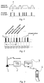
- These '1'-bits B can be transmitted as short IR pulses P, shown in figure 1, whereby we can utilize the high pulse effects mentioned above.
- the receiver simply has to detect whether an IR pulse was sent or not.
- each direction must have a data channel of its own, in which keypad information is transmitted on one channel and display information is transmitted on the other channel from the radio unit to the handset.
- the data transmission capacity of the data channels is not necessarily very high, because transmission of keypad information and updating of display information is possible also with a relatively slow data transmission rate ( ⁇ 100 bit/s).
- there are four digital channels to be transmitted two speech and two data channels). Because the transmission of a short infrared pulse occupies a broad frequency band, it is useful to transmit the channel bits alternating on the infrared transmission path, whereby each channel can utilize the whole frequency band in turn, i.e. time division multiplexing (TDM) is used as the multiplexing method.
- TDM time division multiplexing
- the channels could of course be in any other order.
- the information is transmitted on time division multiplexed channels, because they do not cause mutual interference. It is also possible to transmit the information in some other digital form than time division multiplex.
- Halving the bit rate also enables the halving of the current supplied to the transmitter component, preferably an IR-LED, also e.g. a laser diode, which is the component in the transmitter requiring the highest current.
- halving the pulse length makes it possible to decrease the size of the said current component to be 1/ - 2 of the previous value.
- the current required by the transmitter component can be decreased in total to a fraction of 1/(2*-2) - 1/2,8 of the previous value.
- the speech into a bit stream such as the pulse code modulation (PCM) adaptive differential pulse code modulation (ADPCM), or the continuously variable slope delta modulation (CVSD), or any other suitable modulation method, preferably however, the CVSD-method is used.
- PCM pulse code modulation
- ADPCM adaptive differential pulse code modulation
- CVSD continuously variable slope delta modulation
- the PCM encoder encodes the speech into a bit stream having the rate 64 kbit/s. Normal speech contains plenty of pauses, during which the PCM encoded signal contains only '0'-bits. When this encoding method is used it is advisable to invert the bit stream transmitted by the base section BASE prior to infrared transmission to the external device (handset HS), whereby an IR pulse is caused by each '0'-bit and not by the '1'-bits. Then it is guaranteed that the external device can receive sufficiently many IR pulses from the base section BASE in order to maintain the synchronization of the recovered clock.
- PCM encoding is used in the public telephone network, and generally the PCM encoding circuits contain the required filtering structures as well as the encoding and decoding functions, the origin of their name 'codec circuits'.
- ADPCM circuit Adaptive Differential Pulse Code Modulation
- CT2 Cordless Telecommunications, second generation
- DECT Digital European Cordless Telecommunications
- Microcircuits have been developed for the use in the equipment of these systems, the circuits comprising an ADPCM codec and further microphone and earphone amplifiers including the required filters. These circuits are rather expensive, at least at present, because they are versatile and still quite new. A lower bit stream rate causing a more infrequent transmission of the IR pulses provides a lower power consumption and transmission of pulses at a higher power level.
- CVSD modulator or a Continuously Variable Slope Delta Modulator.
- the bit rate in the CVSD system is directly determined by the modulator clock frequency, which can be freely selected within the range 10 to 64 kHz. The higher the clock frequency, the higher quality speech is transmitted.
- the speech quality of the PCM system normally used in the public telephone network is achieved in the CVSD system already at a bit rate of 32 kbit/s (at least according to circuit manufacturers).
- CVSD is an excellent compromise between bit rate and the complexity of the realization.
- a sequence '...101010...' is transmitted in the CVSD system, which means that pulses arrive at a frequency, which is half of the clock frequency used in the CVSD modulator. Then no sounds are heard in the telephone, but the external device clock maintains its synchronization.
- the transmission of the '...101010...' sequence is interrupted when a speech signal is again received from the radio unit. Because the system inherently seeks to remove long strings of '1's and '0's (in order to decrease the slope distortion), the CVSD system will have no situations where the recovered external device clock would drift out of synchronization.
- Figures 1 and 2 in connection with speech encoding and transmission.
- the invention is described below with reference to Figure 3, which shows the main parts of the system: the radio unit 2 or the transceiver 2 operating at radio frequency, an infrared transceiver 3 which here is a so called base section connected by a line to the transceiver unit, and a handset 4 representing the external device and operating on the infrared connection and communicating with the base section 3; and with reference to the Figure 4, which shows the embodiments of the handset and the infrared transceiver 3 as block diagrams, as well as the connection to the telephone section 2.
- the invention is not limited to the embodiment shown in Figure 4, but figure 4 is an alternative for the realization of the invention in accordance with the claims.
- the multiplexing could be realized e.g. according to Figure 2, whereby the first time slot transmits speech received by the radio telephone via the radio unit base section 3 to the external device, e.g. the handset 4.
- the second time slot transmits to the handset display information shown in its display.
- the third time slot transmits speech from the handset 4 to the radio unit base section 3, and the fourth time slot transmits keypad information supplied by the user to the radio telephone 2 via the base section 3.
- This period must be shared by the four channels to be transmitted, or each channel can have a period of about 4 ⁇ s, in which any IR pulse corresponding to the '1'-bit must be transmitted.
- the system clocks of the external device (handset 4) and the IR transceiver unit 4 in the radio unit 2 must be mutually synchronized so that both will know at which moment each channel is to be transmitted.
- the clock of the base section 3 can be used as the master clock.
- the base section 3 transmits its IR pulses in synchronism with its clock, so that the receiver unit of the external device 4 can recover the clock from the pulse sequence which it receives.
- the data channels will transmit information very infrequently, and thus the clock must be recovered from the speech bit stream. IR pulses must be received sufficiently often so that the recovered clock will maintain its synchronism.
- the radio unit and the external device both will have a microprocessor controlling their functions, so that information transmission and reception occur at predetermined moments according to the clocks.
- the IR pulse length tp (figure 2) could be about 2 ⁇ s at its minimum.
- the IR signal pulse ratio: tp/T 0,128.
- the mentioned pulse length and pulse ratio we can use e.g. 550 mA pulse currents to control the IR-LED, depending however on the IR-LED to be used.
- the data channel bit rate transmitted in the same direction, and using the same IR LEDs is so low compared to the speech channel bit rate that it has a negligible influence on the average drive current of the IR-LED.
- the bit rate of the digital signal resulting from the speech encoding has a critical effect on improving the signal to noise ratio S/N without increasing the power consumption of the handset.
- the infrared communication device comprises a external device section (which in Figure 2 is shown as a handset section 4) and the base section 3, which is connected to the radio telephone or radio unit 2 comprising an RF transceiver, duplex data and/or digitally encoded speech being transmitted as pulse-like infrared signals between the handset and the base section BASE.
- These four (or two, if only speech or data is transmitted) digital channels can be time division multiplexed on the infrared transmission path according to Figure 2. Due to the time division the clocks of the external device and the base section BASE are mutually synchronized.
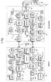
- FIG. 4 One possible realization of the radio telephone system is shown in Figure 4 as a block diagram, in which for an example the external device is represented by a handset 4.
- the radio unit 2 is connected to the base section interface block 100 through the microphone line MIC, the earphone line EAR and the internal data transmission bus DBUS.
- the speech signal received by the base section BASE from the handset HS is supplied to the microphone line in a corresponding way as in the case of an external device connected to the telephone 2 by an electrical cord, whereby the signal is amplified in the telephone and transmitted via the antenna.
- the signal received by the telephone antenna is supplied to the earphone line EAR, whereby the speech signal received via the earphone line EAR is directed to the transmit branch of the base section 3 in order to be transmitted to the handset 4.
- the interface of the data flow to and from the handset 4 to the telephone's data bus DBUS is also made in the interface block 100.
- the master clock block 101 contains a clock oscillator locked to a crystal.
- the clock signal 22 obtained as output is supplied to the control logic block 102, which controls the transmit and receive as well as the data transmission functions.
- the speech signal 10 received on the earphone line EAR by the interface block 100 and to be transmitted to the handset 4 is low-pass filtered in the low-pass filter 103, after which it is encoded into digital form in the speech encoding block 104 using a speech encoding method, preferably the CVSD method.
- the pulse shaper block 105 the digitized speech signal 11 is transformed into a pulse sequence containing short pulses 12, whereby the individual pulses are further transmitted by the infrared transmitter block 106 to the handset HS in a time slot reserved for this speech channel (time slot 1, Figure 2).
- Data 13 (display data) received from the telephone's data transmission bus DBUS and intended to be transmitted to the handset 4 is stored into the TX data buffer block 107.
- the data is timed by the control logic 102 and transmitted further to the pulse shaper block 108, whereby the individual pulses in the pulse sequence generated from the data 14 are transmitted to the handset 4 by the infrared transmitter 106 in the time slot reserved for this data channel time slot 2, Figure 2).
- the infrared receiver block 109 of the base section BASE receives the infrared pulses transmitted by the handset 4.
- the control logic 102 outputs time slot selection signals 15, 16, which at the correct moment open the signal path for a speech channel pulse 17 (time slot 3, Figure 2), and the data channel for the pulse 18 (time slot 4, figure 2) to be received.
- the automatic gain control block 110 (block AGC) controls the gain of the infrared receiver 109 in accordance with the signal strength.
- the pulse stretching block 111 transforms the pulses received in the speech channel time slot into a binary digital signal 19, which is supplied to the speech decoding block 112.
- the analog speech signal 20 obtained from the speech decoding block 112 is low-pass filtered by the low-pass filter 113, after which it is supplied via the interface block 100 to the telephone's microphone line MIC.
- the pulse stretching block 114 transforms the pulses received in the data channel time slot into a binary digital signal 21, which is transmitted to the RX data buffer block 115 and via the interface block 100 to the telephone's data transmission bus DBUS.
- the structure of the handset 4 is to a great extent similar to that of the base section 3.
- the difference to the base section is the absence of the interface block 100 and the recovery of the clock signal.
- the handset has a microphone 200 and an earphone 201, and instead of the data transmission bus a display unit 202 and a keypad 203.
- the control logic block 204 which controls the receiving and transmitting functions as well as the data transmission functions in the handset HS, receives from the clock recovery block 205 a clock signal 30, which is synchronized to the pulse sequence received by the infrared receiver 206, which in turn is synchronized to the master clock 101 of the base section.
- the handset's control logic block 204 is able to open, by the switches 207, 208 controlled by the time slot signals 31, 32, 35, 36, the signal paths for the received speech channel pulses 33 (time slot 1), and for the data channel pulses 34 (time slot 2), and to direct the transmitted pulses of the speech channel 37 (time slot 3) and data channel 38 (time slot 4) in the correct time slots to the infrared transmitter 209.
- the other blocks 210 - 214 of the handset's 4 transmitter section perform the corresponding functions as the transmitter section blocks 103 - 108 of the base section BASE
- the other blocks 215 - 220 of the receiver section is the handset 4 perform the corresponding functions as the receiver section blocks of the base section BASE.
- the external device can be any device, which can be connected to a radio telephone, e.g. a computer or a telecopier. It is prior known to transfer data from and to a computer or telecopier by connection to a radio telephone. For such a connection the computer or telecopier 300 is provided e.g.
- PCMCIA data card 302 Personal Computer Memory Card International Association
- PCMCIA data card 302 Personal Computer Memory Card International Association
- modem for data and telecopier
- PCMCIA slot into which the PCMCIA data card 302 is pushed when one wishes to use the computer or telecopier 300 with a phone as illustrated in figure 5.
- the infrared connection 303 between the radio unit 301 and the computer/telecopier 300 would be between the radio phone 301 and the PCMCIA data card 302, which thereby communicates with the radio phone 301 through the infrared connection 303.
- the necessary device implementation (as shown in figure 4) can in this case be implemented in the computer, preferably in the PCMCIA card, whereby the implementation can be similar to the one shown for the base section in figure 4.
- Data from a computer or telecopier is converted in correct form for the radio telephone in the PCMCIA data card and this converted data can be transmitted by the radio telephone without any conversion when the radio telephone system is digital.
- the interface between the PCMCIA data card and the computer can be similar to a prior known interface.
- the infrared connection 303 (which may be wireless or optical cable) in this only replaces an electrical wire connection between the PCMCIA data card 302 and the radio telephone 301.
- Another possible realization of a computer or telecopier connected to a radio telephone by an infrared connection is to have a built-in-modem in the radio telephone, whereby there is no need for modem functions in the PCMCIA data card.
- the modem converts received data (received by the radio telephone as a rf-signal) to transportable form and the data is converted into asynchronous serial format e.g. in a UART unit (Universal Asynchronous Receiver Transmitter), which forwards the data to an infrared transmitter transmitting the data to the computer in asynchronous serial form (to the PCMCIA unit, from which the connection to the computer is parallel).
- UART unit Universal Asynchronous Receiver Transmitter
- the necessary signals are transmitted from the radio telephone as infrared pulses to the PCMCIA data card, which converts these signals to appropriate form for the computer.
- the signals can be as shown in figure 4, MIC (sent data/speech), EAR (received data/speech) and data bus DBUS signals.
- the computer sends data through the radio telephone, the data is converted to MIC, EAR and data bus signals in the PCMCIA data card and transmitted to the radio telephone via the infrared link.
- the necessary conversions are made in the radio telephone as explained here previously before sending the data through the radio frequency connection.
- the arrangement comprises a reliable radio telephone communication link to an external device operating on a two-directional infrared connection, by which it is possible to transmit both speech and data in both directions, or alternatively only speech or data, having a low average power consumption. Because the external device operates on an infrared connection no radio pollution is generated when a handset according to the invention is used in a car. Moreover, the infrared signal does not spread outside the car, and regarding call protection the arrangement according to the invention is safer than a handset operating on an RF connection. Besides implementing a wireless infrared connection, also an optical cable can be used.
Abstract
Description
- The present invention relates to a radio telephone system comprising a transceiver unit and a device in infrared signal communication with the transceiver unit. The invention also relates to a method of transmitting information between the device and the transceiver unit.
- The user interface of a telephone, particularly in a car radio telephone, normally comprises a receiver part and an operating section (the keypad section). The receiver and the operating section may be combined or may be separate. When they are combined the operating section is often located on the rear of the receiver. The assembly comprising the receiver and the operating section is here called a handset (HS, Hand Set).
- Normally the operating section is connected via a cable to a bracket having a cable connection to the subscriber unit, in a car radio telephone to the radio unit or the transceiver unit of the car radio telephone. In a car radio telephone the receiver and the operating section of the telephone are normally connected via a cable to the radio unit also when they are separately located. In a conventional telephone the operating section of the telephone is normally located in the subscriber unit. Mobile phones are becoming increasingly common, in business as well as in private use, and they are used i.e. in cars and boats. A drawback of mobile phones has been the connection of the transceiver unit to the handset via a cable, which ties the user to the site of the radio unit when the user desires to make and/or to receive calls. For instance in a car the handset is further fixed by the cord to the neighbourhood of the front seat in the car, whereby persons sitting in the car's back seat experience difficulties using the phone.
- The use of the phone was made more flexible when the receiver or the whole handset was replaced by a receiver or handset based on radio frequency or infrared/ultrasonic communication. It is known to use wireless handsets in subscriber sets operating in the conventional public telephone network, whereby the communication between the handset and the subscriber set usually operates on an analog RF link. Wireless handsets usually operate on RF channels at frequencies below 50 MHz and with a power below 100 mW. Different handsets all operate approximately at the same frequencies, and therefore interference between handsets will occur. These wireless handsets further receive interference from television, police and other radios operating at the same frequencies. US Patent No. 4,745,632 presents a wireless mobile phone system, which combines a conventional mobile phone and a conventional subscriber set comprising a wireless handset. Certainly this is a solution requiring much space, when there are two pairs of interconnected handsets and subscriber sets. US Patent No. 4,659,878 presents a mobile phone comprising a wireless handset, in which the connection between the handset and the radio unit is an RF connection without interference. One disadvantage of an RF connection is certainly that at present a car contains a large number of different electronic devices, and thus much electromagnetic radiation or radio pollution is created. Further, if the car contains a large number of devices using RF connections they easily cause mutual interference.
- European Patent Application, EP-A-3 165 058 A presents a telephone having a receiver in wireless analog infrared communication with the subscriber set. A wireless connection as a secondary embodiment between the handset and the transceiver is shown in US Patent No. 4,219,411. Here the primary connection is a cable connection, and if the connection is wireless, then the operation has to be controlled by a direction switch. The connection is primarily operated by the cable, even if the patent mentions the wireless as one possibility. The wireless connection in first place is conceived for the control operations of the telephone, and not for speech transmission. This is mainly due to the fact that difficulties occur when attempting speech transmission over an infrared connection.
- There has been a problem in providing sufficient infrared power in the car cabin so that the wireless device would operate regardless of its location in the car. A limiting factor in achieving a sufficient infrared power is the maximum continuously emitted power which the infrared LEDs can provide. In analog infrared connections the continuous power demand is often so high that the operating time will be short for a handset operating with a battery. EPO Finnish patent No. FI-82334 (corresponding European
patent application EP 0 383 277) presents a system having a separate wireless receiver and a separate wireless operating section. In this system the operating section is unidirectional, i.e., because it has no receiver it can only issue control commands. - According to a first aspect of the present invention there is provided a radio telephone system comprising a transceiver unit and an external device in infrared signal communication with the transceiver unit via an infrared link, characterized in that the infrared signals to be transmitted between the transceiver unit and the external device are transmitted in digital pulsed form.
- According to a second aspect of the present invention there is provided a method of transmitting information between an external device and a transceiver unit as an infrared signal, characterized in that the signal is transmitted in a digital pulsed form.
- An advantage of the present invention is the provision of a radio telephone system with which it is possible to realize a reliable communication between a radio transceiver and an external device, while maintaining a very low power consumption.
- Another advantage of the present invention is the provision of a radio telephone system and a method of operation, with which it is possible to realize a reliable two-directional radio telephone connections, with which speech and data can be transmitted in two directions, keeping the power consumption low.
- Such an arrangement and method can be realized using infrared communication between the external device, such as the radio telephone handset, and the radio unit, the communication being digital and comprising four time division multiplexed digital channels, a speech and a data channel in each direction.
- Alternatively, only speech or data channels can be arranged. The channels carry digitized speech and data in digital form so that in the direction from the external device (the handset) to the radio unit one of the channels transmits digitized speech and the second transmits data, e.g. keypad information. In the opposite direction one of the channels transmit digitized speech and the other data, e.g. display information. The data channels can also transmit other data than keypad and display information.
- When speech and data are digital it is possible to transmit them as short infrared pulses, whereby the infrared emitter, preferably an IR-LED, can momentarily output an emitted power which is tens of times higher without increasing the average power consumption; in other words the power consumption of the IR transmitter can be reduced to a fraction, however without impairing the signal to noise ratio. The smaller the duty cycle is or the narrower the IR pulse is, and the less frequently it is transmitted, the higher the momentarily emitted power can be. The average power consumption can also be reduced when the IR pulses are transmitted less frequently.
- The infrared connection between the radio unit and the external device, such as a handset, can be realized as a wireless connection or by the use of an optical cable. The information must be in digital form so that it can be transmitted as IR pulses, and thus the speech must be digitally encoded. When the speech is digitally encoded the obtained bit stream can be transmitted on the infrared transmission path using binary amplitude modulation (ASK, Amplitude Shift Keying), in which the relative amplitude of the transmitted carrier is one for a transmitted '1'-bit, and zero for a transmitted '0'-bit. The emitting frequency of the IR-LED can be used as the modulating carrier, whereby only the '1'-bits cause infrared emission when the bit stream is transmitted. These '1'-bits B can be transmitted as short IR pulses P, shown in figure 1, whereby we can utilize the high pulse effects mentioned above. The receiver simply has to detect whether an IR pulse was sent or not.
- In a radio telephone operating with a handset it has to be possible to transmit speech simultaneously in two directions. Further each direction must have a data channel of its own, in which keypad information is transmitted on one channel and display information is transmitted on the other channel from the radio unit to the handset. The data transmission capacity of the data channels is not necessarily very high, because transmission of keypad information and updating of display information is possible also with a relatively slow data transmission rate ( < 100 bit/s). Thus there are four digital channels to be transmitted (two speech and two data channels). Because the transmission of a short infrared pulse occupies a broad frequency band, it is useful to transmit the channel bits alternating on the infrared transmission path, whereby each channel can utilize the whole frequency band in turn, i.e. time division multiplexing (TDM) is used as the multiplexing method.
- The channels could of course be in any other order. Preferably the information is transmitted on time division multiplexed channels, because they do not cause mutual interference. It is also possible to transmit the information in some other digital form than time division multiplex.
- Instead of improving the S/N ratio it is possible by the above measures to decrease the power consumption of the transmitter, without impairing the received S/N ratio. Halving the bit rate also enables the halving of the current supplied to the transmitter component, preferably an IR-LED, also e.g. a laser diode, which is the component in the transmitter requiring the highest current. On the other hand, halving the pulse length makes it possible to decrease the size of the said current component to be 1/ - 2 of the previous value. The current required by the transmitter component can be decreased in total to a fraction of 1/(2*-2) - 1/2,8 of the previous value.
- When we calculated the pulse rates above, we assumed that only '1'-bits were to be transmitted, i.e. that an infrared pulse is transmitted in each time slot of the channel. In practice the digitally encoded speech also contains plenty of '0'-bits, during which no IR pulses are transmitted. Thus the effective pulse ratio will be lower than mentioned above, which enables the use of somewhat higher pulse currents.
- In the method and the arrangement in accordance with the invention it is possible to use different methods to encode the speech into a bit stream, such as the pulse code modulation (PCM) adaptive differential pulse code modulation (ADPCM), or the continuously variable slope delta modulation (CVSD), or any other suitable modulation method, preferably however, the CVSD-method is used.
- The PCM encoder encodes the speech into a bit stream having the rate 64 kbit/s. Normal speech contains plenty of pauses, during which the PCM encoded signal contains only '0'-bits. When this encoding method is used it is advisable to invert the bit stream transmitted by the base section BASE prior to infrared transmission to the external device (handset HS), whereby an IR pulse is caused by each '0'-bit and not by the '1'-bits. Then it is guaranteed that the external device can receive sufficiently many IR pulses from the base section BASE in order to maintain the synchronization of the recovered clock. On the other hand it is not advisable to invert the PCM code transmitted by the external device, because then the external device is not required to transmit IR pulses during pauses in the speech and thus power is saved. PCM encoding is used in the public telephone network, and generally the PCM encoding circuits contain the required filtering structures as well as the encoding and decoding functions, the origin of their name 'codec circuits'.
- The encoding of the bit stream generated by the PCM encoder at 64 kbit/s into a slower bit stream comes off with an ADPCM circuit (Adaptive Differential Pulse Code Modulation), which decreases the bit stream rate to 32, 24 or 16 kbit/s. The price of ADPCM circuits designed to cooperate with a separate PCM codec is of the same magnitude as the codec itself, so that we get a rather high increase of the component costs when we use this encoding method. CT2 (Cordless Telecommunications, second generation) and DECT (Digital European Cordless Telecommunications) are standards for the digital wireless telephone, both using ADPCM encoding at a rate of 32 kbit/s to encode the speech. Microcircuits have been developed for the use in the equipment of these systems, the circuits comprising an ADPCM codec and further microphone and earphone amplifiers including the required filters. These circuits are rather expensive, at least at present, because they are versatile and still quite new. A lower bit stream rate causing a more infrequent transmission of the IR pulses provides a lower power consumption and transmission of pulses at a higher power level.
- An inexpensive and simple way to encode the speech into digital form is to use a CVSD modulator or a Continuously Variable Slope Delta Modulator. The bit rate in the CVSD system is directly determined by the modulator clock frequency, which can be freely selected within the range 10 to 64 kHz. The higher the clock frequency, the higher quality speech is transmitted. The speech quality of the PCM system normally used in the public telephone network is achieved in the CVSD system already at a bit rate of 32 kbit/s (at least according to circuit manufacturers). However, while very advanced speech compression methods are available providing lower bit rates, CVSD is an excellent compromise between bit rate and the complexity of the realization. During pauses in the speech a sequence '...101010...' is transmitted in the CVSD system, which means that pulses arrive at a frequency, which is half of the clock frequency used in the CVSD modulator. Then no sounds are heard in the telephone, but the external device clock maintains its synchronization. The transmission of the '...101010...' sequence is interrupted when a speech signal is again received from the radio unit. Because the system inherently seeks to remove long strings of '1's and '0's (in order to decrease the slope distortion), the CVSD system will have no situations where the recovered external device clock would drift out of synchronization.
- In PCM the significance of the most significant bit in the 8-bit code is clearly higher than that of the least significant bit, while in the CVSD code each bit has about the same significance. Therefore speech interference caused by bit errors in the transmission are not as annoying as in the case of PCM. Due to the above mentioned features it is preferred to use the CVSD method as the speech encoding method in the method and arrangement according to the invention.
- Embodiments of the present invention are described herewith, by way of example, with reference to the accompanying drawings in which;
- Figure 1 shows binary amplitude modulation of an infrared signal;
- Figure 2 shows the time division multiplexing of the channels;
- Figure 3 shows a telephone system in accordance with the invention;
- Figure 4 shows a basic block diagram of a telephone system in accordance with the invention; and
- Figure 5 shows another telephone system in accordance with the invention.
- Above reference was made to Figures 1 and 2 in connection with speech encoding and transmission. The invention is described below with reference to Figure 3, which shows the main parts of the system: the
radio unit 2 or thetransceiver 2 operating at radio frequency, aninfrared transceiver 3 which here is a so called base section connected by a line to the transceiver unit, and ahandset 4 representing the external device and operating on the infrared connection and communicating with thebase section 3; and with reference to the Figure 4, which shows the embodiments of the handset and theinfrared transceiver 3 as block diagrams, as well as the connection to thetelephone section 2. The invention is not limited to the embodiment shown in Figure 4, but figure 4 is an alternative for the realization of the invention in accordance with the claims. - The multiplexing could be realized e.g. according to Figure 2, whereby the first time slot transmits speech received by the radio telephone via the radio
unit base section 3 to the external device, e.g. thehandset 4. The second time slot transmits to the handset display information shown in its display. The third time slot transmits speech from thehandset 4 to the radiounit base section 3, and the fourth time slot transmits keypad information supplied by the user to theradio telephone 2 via thebase section 3. - If the speech is encoded into a 64 kbit/s bit stream (e.g. standard PCM coding), one bit period T = 1/64000 s = about 16 µs (figure 2). This period must be shared by the four channels to be transmitted, or each channel can have a period of about 4 µs, in which any IR pulse corresponding to the '1'-bit must be transmitted. When time division multiplexing is used, the system clocks of the external device (handset 4) and the
IR transceiver unit 4 in theradio unit 2 must be mutually synchronized so that both will know at which moment each channel is to be transmitted. The clock of thebase section 3 can be used as the master clock. Thebase section 3 transmits its IR pulses in synchronism with its clock, so that the receiver unit of theexternal device 4 can recover the clock from the pulse sequence which it receives. In practice the data channels will transmit information very infrequently, and thus the clock must be recovered from the speech bit stream. IR pulses must be received sufficiently often so that the recovered clock will maintain its synchronism. The radio unit and the external device both will have a microprocessor controlling their functions, so that information transmission and reception occur at predetermined moments according to the clocks. - Let us assume that the bit rate is 64 kbit/s, whereby T = 15,625 µs. When an inexpensive GaAs LED having a rise time slightly less than 1 µs is used as the infrared transmitter component, then the IR pulse length tp (figure 2) could be about 2 µs at its minimum. Then we obtain the IR signal pulse ratio: tp/T = 0,128. With the mentioned pulse length and pulse ratio we can use e.g. 550 mA pulse currents to control the IR-LED, depending however on the IR-LED to be used. Then we assumed that the data channel bit rate transmitted in the same direction, and using the same IR LEDs, is so low compared to the speech channel bit rate that it has a negligible influence on the average drive current of the IR-LED.
- If we can encode the speech so that the bit rate is only 32 kbit/s we can halve the pulse ratio of the infrared signal (tp/T = 0,064), whereby the drive current of the IR-LED can be increased from 550 mA to about 1 A, that is by a factor of about 1,82. The momentary emission power of the infrared signal also increases in the same proportion. The emission received by the active surface of the PIN diode operating as the receiving component also increases in the same proportion, so that also the signal current provided by the PIN diode increases by a factor of 1,82. The received signal to noise ratio S/N increases thus by 20
log 1,82 dB - 5,2 dB. Thus the bit rate of the digital signal resulting from the speech encoding has a critical effect on improving the signal to noise ratio S/N without increasing the power consumption of the handset. - If a faster IR-LED is available we can shorten the pulse length from two microseconds to e.g. one microsecond. Then the pulse ratio is again halved, enabling an increase of the pulse current. When the pulse length tp is shortened to one microsecond we obtain the pulse ratio tp/T = 0,032. Now we can use current pulses of e.g. 1,8 A to drive the IR-LED. The bandwidth of the receiver must be doubled in order to receive the pulse shortened to one half. The doubled noise bandwidth corresponds to an increase in the noise current by the factor -2. The received signal to noise ratio is then improved by 20 log (1,8 A/1 A/-2) dB - 2,1 dB. The combined effect of halving the bit rate and the IR pulse length tp leads to an improvement of the received signal to noise ratio S/N by about 7,3 dB, without increasing the transmitter power consumption.
- The infrared communication device comprises a external device section (which in Figure 2 is shown as a handset section 4) and the
base section 3, which is connected to the radio telephone orradio unit 2 comprising an RF transceiver, duplex data and/or digitally encoded speech being transmitted as pulse-like infrared signals between the handset and the base section BASE. These four (or two, if only speech or data is transmitted) digital channels can be time division multiplexed on the infrared transmission path according to Figure 2. Due to the time division the clocks of the external device and the base section BASE are mutually synchronized. - One possible realization of the radio telephone system is shown in Figure 4 as a block diagram, in which for an example the external device is represented by a
handset 4. Theradio unit 2 is connected to the basesection interface block 100 through the microphone line MIC, the earphone line EAR and the internal data transmission bus DBUS. The speech signal received by the base section BASE from the handset HS is supplied to the microphone line in a corresponding way as in the case of an external device connected to thetelephone 2 by an electrical cord, whereby the signal is amplified in the telephone and transmitted via the antenna. Correspondingly the signal received by the telephone antenna is supplied to the earphone line EAR, whereby the speech signal received via the earphone line EAR is directed to the transmit branch of thebase section 3 in order to be transmitted to thehandset 4. The interface of the data flow to and from thehandset 4 to the telephone's data bus DBUS is also made in theinterface block 100. - The
master clock block 101 contains a clock oscillator locked to a crystal. Theclock signal 22 obtained as output is supplied to thecontrol logic block 102, which controls the transmit and receive as well as the data transmission functions. - The speech signal 10 received on the earphone line EAR by the
interface block 100 and to be transmitted to thehandset 4 is low-pass filtered in the low-pass filter 103, after which it is encoded into digital form in thespeech encoding block 104 using a speech encoding method, preferably the CVSD method. In thepulse shaper block 105 the digitized speech signal 11 is transformed into a pulse sequence containingshort pulses 12, whereby the individual pulses are further transmitted by theinfrared transmitter block 106 to the handset HS in a time slot reserved for this speech channel (time slot 1, Figure 2). - Data 13 (display data) received from the telephone's data transmission bus DBUS and intended to be transmitted to the
handset 4 is stored into the TXdata buffer block 107. The data is timed by thecontrol logic 102 and transmitted further to thepulse shaper block 108, whereby the individual pulses in the pulse sequence generated from thedata 14 are transmitted to thehandset 4 by theinfrared transmitter 106 in the time slot reserved for this datachannel time slot 2, Figure 2). - The
infrared receiver block 109 of the base section BASE receives the infrared pulses transmitted by thehandset 4. Thecontrol logic 102 outputs time slot selection signals 15, 16, which at the correct moment open the signal path for a speech channel pulse 17 (time slot 3, Figure 2), and the data channel for the pulse 18 (time slot 4, figure 2) to be received. The automatic gain control block 110 (block AGC) controls the gain of theinfrared receiver 109 in accordance with the signal strength. - The
pulse stretching block 111 transforms the pulses received in the speech channel time slot into a binarydigital signal 19, which is supplied to thespeech decoding block 112. Theanalog speech signal 20 obtained from thespeech decoding block 112 is low-pass filtered by the low-pass filter 113, after which it is supplied via theinterface block 100 to the telephone's microphone line MIC. - The
pulse stretching block 114 transforms the pulses received in the data channel time slot into a binarydigital signal 21, which is transmitted to the RX data buffer block 115 and via theinterface block 100 to the telephone's data transmission bus DBUS. - The structure of the
handset 4 is to a great extent similar to that of thebase section 3. The difference to the base section is the absence of theinterface block 100 and the recovery of the clock signal. Instead of the earphone and microphone lines the handset has amicrophone 200 and anearphone 201, and instead of the data transmission bus adisplay unit 202 and akeypad 203. Thecontrol logic block 204, which controls the receiving and transmitting functions as well as the data transmission functions in the handset HS, receives from the clock recovery block 205 aclock signal 30, which is synchronized to the pulse sequence received by the infrared receiver 206, which in turn is synchronized to themaster clock 101 of the base section. When the clock signals 22, 30 of the base section and the handset are thus mutually synchronized, the handset'scontrol logic block 204 is able to open, by theswitches infrared transmitter 209. The other blocks 210 - 214 of the handset's 4 transmitter section perform the corresponding functions as the transmitter section blocks 103 - 108 of the base section BASE, and the other blocks 215 - 220 of the receiver section is thehandset 4 perform the corresponding functions as the receiver section blocks of the base section BASE. - The above presented examples concern the implementation of an infrared link according to the invention between a radio transceiver and a handset. Besides a handset, the external device can be any device, which can be connected to a radio telephone, e.g. a computer or a telecopier. It is prior known to transfer data from and to a computer or telecopier by connection to a radio telephone. For such a connection the computer or
telecopier 300 is provided e.g. with a PCMCIA data card 302 (Personal Computer Memory Card International Association), which may include a modem (for data and telecopier) and which can either be built in the computer or telecopier or the computer or telecopier may have a PCMCIA slot, into which thePCMCIA data card 302 is pushed when one wishes to use the computer ortelecopier 300 with a phone as illustrated in figure 5. - For using a computer or telecopier 300 (shown as a computer) as the external device in the arrangement according to the invention (shown in figure 5), the
infrared connection 303 between theradio unit 301 and the computer/telecopier 300 would be between theradio phone 301 and thePCMCIA data card 302, which thereby communicates with theradio phone 301 through theinfrared connection 303. The necessary device implementation (as shown in figure 4) can in this case be implemented in the computer, preferably in the PCMCIA card, whereby the implementation can be similar to the one shown for the base section in figure 4. Data from a computer or telecopier is converted in correct form for the radio telephone in the PCMCIA data card and this converted data can be transmitted by the radio telephone without any conversion when the radio telephone system is digital. The interface between the PCMCIA data card and the computer can be similar to a prior known interface. The infrared connection 303 (which may be wireless or optical cable) in this only replaces an electrical wire connection between thePCMCIA data card 302 and theradio telephone 301. - Another possible realization of a computer or telecopier connected to a radio telephone by an infrared connection according to the invention is to have a built-in-modem in the radio telephone, whereby there is no need for modem functions in the PCMCIA data card. The modem converts received data (received by the radio telephone as a rf-signal) to transportable form and the data is converted into asynchronous serial format e.g. in a UART unit (Universal Asynchronous Receiver Transmitter), which forwards the data to an infrared transmitter transmitting the data to the computer in asynchronous serial form (to the PCMCIA unit, from which the connection to the computer is parallel). When the computer sends data through the radio telephone the previous steps are performed in reverse order. This kind of realization can well be used in both analog and digital radio communication systems.
- In an analog radio communication system the necessary signals are transmitted from the radio telephone as infrared pulses to the PCMCIA data card, which converts these signals to appropriate form for the computer. The signals can be as shown in figure 4, MIC (sent data/speech), EAR (received data/speech) and data bus DBUS signals. When the computer sends data through the radio telephone, the data is converted to MIC, EAR and data bus signals in the PCMCIA data card and transmitted to the radio telephone via the infrared link. The necessary conversions are made in the radio telephone as explained here previously before sending the data through the radio frequency connection.
- The arrangement comprises a reliable radio telephone communication link to an external device operating on a two-directional infrared connection, by which it is possible to transmit both speech and data in both directions, or alternatively only speech or data, having a low average power consumption. Because the external device operates on an infrared connection no radio pollution is generated when a handset according to the invention is used in a car. Moreover, the infrared signal does not spread outside the car, and regarding call protection the arrangement according to the invention is safer than a handset operating on an RF connection. Besides implementing a wireless infrared connection, also an optical cable can be used.
- In view of the foregoing it will be clear to a person skilled in the art that modifications may be incorporated without departing from the scope of the present invention.
Claims (11)
- A radio telephone system comprising a transceiver unit and an external device in infrared signal communication with the transceiver unit via an infrared link, characterized in that the infrared signals to be transmitted between the transceiver unit and the external device are transmitted in digital pulsed form.
- A system as claimed in claim 1, wherein the signal is transmitted as a wireless infrared signal
- A system as claimed in claim 1, wherein the signal is transmitted through an optical cable.
- A system as claimed in any previous claim, wherein the signal comprises speech and data signals.
- A system as claimed in any previous claim, characterized in that a separate infrared transceiver is connected to the transceiver unit via a cable.
- A system as claimed in any previous claim, wherein information is transmitted between the transceiver unit and the external device in a digital time division multiplexed channel.
- A system as claimed in claim 6, wherein there are four time division multiplexed channels, including one speech channel and one data channel in both directions between the transceiver unit and the external device.
- A system as claimed in claim 6 or claim 7, wherein the external device and the infrared transceiver have means to control the transmission and reception of speech and data and to transmit and receive speech and data at a correct moment in the time division multiplexed digital channels.
- A system as claimed in claim 5, wherein the external device and the infrared transceiver have means capable of encoding speech into digital form.
- A system as claimed in claim 9, wherein the speech encoding means comprise a continuously variable slope delta (CVSD) modulator.
- A method of transmitting information between an external device and a transceiver unit as an infrared signal, characterized in that the signal is transmitted in a digital pulsed form.
Applications Claiming Priority (2)
| Application Number | Priority Date | Filing Date | Title |
|---|---|---|---|
| FI923693A FI109496B (en) | 1992-08-18 | 1992-08-18 | Apparatus and method for providing digital infrared communication between a base unit of a radiotelephone device and another device |
| FI923693 | 1992-08-18 |
Publications (2)
| Publication Number | Publication Date |
|---|---|
| EP0585030A1 true EP0585030A1 (en) | 1994-03-02 |
| EP0585030B1 EP0585030B1 (en) | 1999-03-17 |
Family
ID=8535725
Family Applications (1)
| Application Number | Title | Priority Date | Filing Date |
|---|---|---|---|
| EP93306456A Expired - Lifetime EP0585030B1 (en) | 1992-08-18 | 1993-08-17 | Infrared link between a transceiver and an external device |
Country Status (4)
| Country | Link |
|---|---|
| US (1) | US5636264A (en) |
| EP (1) | EP0585030B1 (en) |
| DE (1) | DE69323942T2 (en) |
| FI (1) | FI109496B (en) |
Cited By (28)
| Publication number | Priority date | Publication date | Assignee | Title |
|---|---|---|---|---|
| DE29501275U1 (en) * | 1995-01-27 | 1995-03-23 | Siemens Ag | Transmitting / receiving arrangement for mobile radio |
| EP0671826A1 (en) * | 1994-03-10 | 1995-09-13 | Pacesetter AB | Device for optical transmissions |
| DE19505199A1 (en) * | 1995-02-16 | 1996-08-29 | Wolfgang Dipl Ing Sachs | Anti-theft radio alarm installation with in-built security |
| GB2300322A (en) * | 1995-04-25 | 1996-10-30 | Siemens Ag | Combined infra-red and telephone communications for computers |
| WO1996037982A1 (en) * | 1995-05-24 | 1996-11-28 | Rosen Paul Gunnar | System related to information-carrying signals |
| EP0766437A1 (en) * | 1995-09-29 | 1997-04-02 | Siemens Aktiengesellschaft | Telecommunications apparatus |
| DE19603295A1 (en) * | 1996-01-30 | 1997-07-31 | Siemens Ag | Optical interface, in particular for diagnosis of an optoelectronic hotplate control |
| EP0790749A2 (en) * | 1995-06-06 | 1997-08-20 | Texas Instruments Incorporated | Infrared interface for data communications |
| EP0806878A2 (en) * | 1996-05-07 | 1997-11-12 | Alcatel | Arrangement for using a mobile terminal in a radio switching system with different transmission standards |
| AU683496B2 (en) * | 1993-11-12 | 1997-11-13 | Alcatel N.V. | Mobile telephone |
| EP0821502A2 (en) * | 1996-07-23 | 1998-01-28 | Nokia Mobile Phones Ltd. | Time division duplex with infrared link |
| WO1998026513A1 (en) * | 1996-12-12 | 1998-06-18 | Siemens Aktiengesellschaft | Mobile telephone |
| WO1998041001A1 (en) * | 1997-03-12 | 1998-09-17 | Nokia Mobile Phones Limited | Portable communication terminal with infrared link |
| GB2324920A (en) * | 1997-04-25 | 1998-11-04 | Nec Corp | Option apparatus for a portable terminal unit |
| EP0713343A3 (en) * | 1994-11-15 | 1999-05-12 | Nec Corporation | Portable multi-information communication device |
| US5940767A (en) * | 1996-05-07 | 1999-08-17 | Ericsson, Inc. | Intelligent docking station for use with a portable wireless receiver to provide expanded short message services |
| EP0948224A2 (en) * | 1997-11-22 | 1999-10-06 | Robert Bosch Gmbh | Wireless data transmission method and intermediate station |
| GB2340347A (en) * | 1998-08-03 | 2000-02-16 | Interpraphone Limited | Language translation facility for mobile telephone |
| EP1042930A1 (en) * | 1997-08-15 | 2000-10-11 | Gn Netcom/Unex Inc. | Infrared wireless headset system |
| GB2354654A (en) * | 1999-09-01 | 2001-03-28 | Siemens Ag | Remotely controlling an apparatus via a spatially limited network and an optical transmitter |
| US6230214B1 (en) | 1997-08-20 | 2001-05-08 | Nokia Mobile Phones, Ltd. | Portable electronic devices |
| EP1401166A1 (en) * | 2002-09-18 | 2004-03-24 | Nippon Telegraph and Telephone Corporation | Method and Device for transmitting speech and music data using return-to-zero-signals |
| EP1466200A1 (en) * | 2002-01-18 | 2004-10-13 | Pegasus Technologies Ltd. | Infrared communications link with attachment configuration |
| JP2007124136A (en) * | 2005-10-26 | 2007-05-17 | Sony Corp | Optical transmission apparatus, and method for controlling output of power supply dc voltage |
| US8041388B2 (en) | 1995-02-15 | 2011-10-18 | Nokia Corporation | Method for using applications in a mobile station, a mobile station, and a system for effecting payments |
| EP2675083A1 (en) * | 2012-06-15 | 2013-12-18 | Outstanding Technology Co., Ltd. | Spatial light communication device |
| US8958700B2 (en) | 2012-06-15 | 2015-02-17 | Vlc Co., Ltd. | Spatial light communication device |
| WO2016001018A1 (en) * | 2014-07-03 | 2016-01-07 | Koninklijke Philips N.V. | Coded light symbol encoding |
Families Citing this family (58)
| Publication number | Priority date | Publication date | Assignee | Title |
|---|---|---|---|---|
| JP2856690B2 (en) * | 1995-03-02 | 1999-02-10 | 日本電気株式会社 | Portable electronic device with infrared communication function |
| JPH09186574A (en) * | 1995-12-28 | 1997-07-15 | Nec Corp | Terminal equipment with detection function |
| US5999798A (en) * | 1996-02-13 | 1999-12-07 | Primax Electronics, Inc. | Computer peripheral device with circuit for wirelessly receiving and transmitting signals |
| CN1214180A (en) * | 1996-03-26 | 1999-04-14 | 英国电讯有限公司 | Alternative routing system for mobile telephone calls |
| FI104138B1 (en) * | 1996-10-02 | 1999-11-15 | Nokia Mobile Phones Ltd | A system for communicating a call and a mobile telephone |
| FI106332B (en) | 1996-12-30 | 2001-01-15 | Nokia Mobile Phones Ltd | Infrared link |
| FI105859B (en) * | 1997-02-21 | 2000-10-13 | Nokia Mobile Phones Ltd | Method for Setting the Audio Parameters of a Digital Signal Processing Unit in an Electronic Device and an Electronic Device |
| US5894425A (en) * | 1997-02-28 | 1999-04-13 | Quantum Corporation | Wireless secondary interface for data storage device |
| DE19708979B4 (en) * | 1997-03-05 | 2006-08-24 | Nokia Mobile Phones Ltd. | System for data communication via an optical bus and method for controlling the system |
| US6256129B1 (en) | 1997-03-28 | 2001-07-03 | Samsung Electronics Co., Ltd. | Portable computer and method of automatically controlling direction of infrared signal transmission and reception |
| KR100229603B1 (en) * | 1997-04-15 | 1999-11-15 | 윤종용 | A computer system provided with infrared communication cable |
| FI105135B (en) | 1997-04-30 | 2000-06-15 | Nokia Mobile Phones Ltd | A system and method for transmitting a call and a mobile station |
| US5860060A (en) * | 1997-05-02 | 1999-01-12 | Texas Instruments Incorporated | Method for left/right channel self-alignment |
| US6901241B2 (en) * | 1998-02-11 | 2005-05-31 | Telefonaktiebolaget L M Ericsson (Publ) | System, method and apparatus for secure transmission of confidential information |
| WO1999052066A1 (en) * | 1998-04-02 | 1999-10-14 | Swisscom Ag | Method for loading data onto chip cards and devices adapted thereto |
| DE59804011D1 (en) * | 1998-05-20 | 2002-06-06 | Swisscom Mobile Ag | METHOD AND ADAPTED APPARATUS FOR THE TREATMENT OF DATA FROM EXTERNAL DEVICES |
| DE59804845D1 (en) * | 1998-05-20 | 2002-08-22 | Swisscom Mobile Ag | METHOD AND APPROPRIATELY ADAPTED DEVICES FOR TREATING PROGRAM-RELATED DIGITAL DATA FROM RADIO PROGRAMS |
| JP2000036702A (en) | 1998-07-21 | 2000-02-02 | Hitachi Ltd | Radio terminal |
| JP3641983B2 (en) * | 1998-11-10 | 2005-04-27 | 日産自動車株式会社 | Mobile phone holding device |
| US6725061B1 (en) * | 1999-01-12 | 2004-04-20 | Qualcomm, Incorporated | System and method for the automatic identification of accessories coupled to a wireless communication device |
| US6501576B1 (en) | 1999-03-24 | 2002-12-31 | Intel Corporation | Wireless data transfer using a remote media interface |
| US6792103B1 (en) * | 1999-04-22 | 2004-09-14 | James H. Walker | Telephonic automatic dialing system |
| FI107493B (en) * | 1999-06-07 | 2001-08-15 | Nokia Mobile Phones Ltd | A data transmission adapter and a method of data transfer |
| US20040160917A1 (en) * | 1999-06-22 | 2004-08-19 | Eliznd Ihab H. | Multibeam antenna for a wireless network |
| DE19934837A1 (en) * | 1999-07-24 | 2001-01-25 | Bosch Gmbh Robert | Adapter card for navigation device has interfaces for exchanging information with adapter card reader, especially chip card reader, and with radio device, especially GSM mobile telephone |
| JP3374798B2 (en) * | 1999-08-23 | 2003-02-10 | 日本電気株式会社 | Portable wireless terminal with infrared communication function and communication method thereof |
| US20030069996A1 (en) * | 1999-08-30 | 2003-04-10 | William M. Parrott | Infrared to radio frequency adapter and method for using the same |
| AU7346800A (en) | 1999-09-02 | 2001-03-26 | Automated Business Companies | Communication and proximity authorization systems |
| US6754259B1 (en) * | 1999-11-10 | 2004-06-22 | International Business Machines Corporation | Low-cost radio frequency (RF) link for point-to-point data transfer |
| EP1113684A1 (en) * | 1999-12-29 | 2001-07-04 | Koninklijke Philips Electronics N.V. | System, device and method of simultaneously connecting to two TDMA transmission systems |
| EP1250771A1 (en) * | 2000-01-13 | 2002-10-23 | Netless Web Wireless, Inc. | Wireless digital high speed communications |
| KR100366637B1 (en) * | 2000-01-28 | 2003-01-09 | 삼성전자 주식회사 | Digital cordless phone system for improving distance of speech communication using error concealment and method thereof |
| US7095981B1 (en) * | 2000-04-04 | 2006-08-22 | Great American Technologies | Low power infrared portable communication system with wireless receiver and methods regarding same |
| JP2002124907A (en) * | 2000-10-13 | 2002-04-26 | Link Evolution Corp | Infrared ray communication adapter |
| US6678536B2 (en) * | 2000-12-07 | 2004-01-13 | Mark Wendell Fletcher | Wireless microphone |
| DE10102280A1 (en) * | 2001-01-18 | 2002-08-14 | Klaus R Mueller | Signal transmission for electrical and electronic devices, esp. mobilephones, uses optical waveguide between phone and input /output device |
| CN100354902C (en) * | 2001-10-05 | 2007-12-12 | 皇家飞利浦电子股份有限公司 | Method of operating a remote control system and a remote control system comprising an RF transmission and receiving system |
| US7027768B2 (en) | 2001-10-12 | 2006-04-11 | Bellsouth Intellectual Property Corporation | Method and systems using a set-top box and communicating between a remote data network and a wireless communication network |
| DE10163774A1 (en) * | 2001-12-22 | 2003-07-03 | Roche Diagnostics Gmbh | Plug-in data transfer module, useful in monitoring medical conditions, comprises an interface at the analysis system, and a communication unit to transmit converted electromagnetic/acoustic signals to a data processing station |
| DE10226329A1 (en) * | 2002-06-07 | 2003-12-18 | Deutsche Telekom Ag | Mobile telephone with distance, angle or speed measuring functions has evaluation unit for measuring propagation time of received laser beam and calculates associated distance |
| AU2003263945A1 (en) * | 2002-08-22 | 2004-03-11 | Atlinks Usa, Inc. | Low-cost high-power digital cordless telephone architecture |
| US8000647B2 (en) * | 2002-10-11 | 2011-08-16 | At&T Intellectual Property I, L.P. | Method using a set-top box and communicating between a remote data network and a wireless communication network |
| US20040193764A1 (en) * | 2003-03-27 | 2004-09-30 | Sony Corporation | PC card with standalone functionality |
| US7587287B2 (en) | 2003-04-04 | 2009-09-08 | Abbott Diabetes Care Inc. | Method and system for transferring analyte test data |
| EP2076974B1 (en) * | 2006-10-16 | 2014-04-23 | Assa Abloy Hospitality, Inc. | Centralized wireless network for multi-room large properties |
| US7990724B2 (en) | 2006-12-19 | 2011-08-02 | Juhasz Paul R | Mobile motherboard |
| US20090144061A1 (en) * | 2007-11-29 | 2009-06-04 | Plantronics, Inc. | Systems and methods for generating verbal feedback messages in head-worn electronic devices |
| US7711018B2 (en) * | 2007-12-21 | 2010-05-04 | Microvision, Inc. | Method and apparatus for laser diode compensation |
| WO2009105115A2 (en) | 2008-02-22 | 2009-08-27 | T-Mobile Usa, Inc. | Data exchange initiated by tapping devices |
| US20100074625A1 (en) * | 2008-09-03 | 2010-03-25 | Northcott John C | Apparatus for voice communication using an incoherent light source |
| US20130052957A1 (en) * | 2011-08-26 | 2013-02-28 | Daniel Noel Badiere | Short-range data communication |
| KR20130093786A (en) * | 2011-12-30 | 2013-08-23 | 한국전자통신연구원 | Modulation method for optical modem and signal transmitting apparatus for performing the method |
| WO2014016695A2 (en) | 2012-07-27 | 2014-01-30 | Assa Abloy Ab | Presence-based credential updating |
| WO2014016705A2 (en) | 2012-07-27 | 2014-01-30 | Assa Abloy Ab | Setback controls based on out-of-room presence information |
| US8983300B1 (en) | 2014-02-06 | 2015-03-17 | Peel Technologies, Inc. | Receiving infrared communications on a mobile device |
| US9965949B2 (en) | 2014-02-06 | 2018-05-08 | Peel Technologies, Inc. | Infrared communications on a mobile device |
| KR20160020860A (en) * | 2014-08-14 | 2016-02-24 | 엘지전자 주식회사 | Mobile terminal and method for controlling the same |
| JP6452030B2 (en) * | 2014-09-09 | 2019-01-16 | パナソニックIpマネジメント株式会社 | Lighting equipment and positioning system |
Citations (2)
| Publication number | Priority date | Publication date | Assignee | Title |
|---|---|---|---|---|
| EP0027833A1 (en) * | 1979-10-30 | 1981-05-06 | Siemens Aktiengesellschaft | Telephone substation |
| WO1992010046A1 (en) * | 1990-12-03 | 1992-06-11 | Light Ideas Incorporated | Light-linked cellular telephone |
Family Cites Families (4)
| Publication number | Priority date | Publication date | Assignee | Title |
|---|---|---|---|---|
| US5086510A (en) * | 1988-12-16 | 1992-02-04 | Robert Bosch Gmbh | Multi-choice information system for a motor vehicle |
| US5315645A (en) * | 1990-12-10 | 1994-05-24 | Tek Electronics Manufacturing Corporation | Communication apparatus utilizing digital optical signals |
| US5343319A (en) * | 1993-06-14 | 1994-08-30 | Motorola, Inc. | Apparatus for adapting an electrical communications port to an optical communications port |
| US5446783A (en) * | 1994-01-31 | 1995-08-29 | Hewlett-Packard Company | Cellular phone with infrared battery pack |
-
1992
- 1992-08-18 FI FI923693A patent/FI109496B/en not_active IP Right Cessation
-
1993
- 1993-08-17 EP EP93306456A patent/EP0585030B1/en not_active Expired - Lifetime
- 1993-08-17 DE DE69323942T patent/DE69323942T2/en not_active Expired - Lifetime
-
1995
- 1995-12-05 US US08/567,634 patent/US5636264A/en not_active Expired - Lifetime
Patent Citations (2)
| Publication number | Priority date | Publication date | Assignee | Title |
|---|---|---|---|---|
| EP0027833A1 (en) * | 1979-10-30 | 1981-05-06 | Siemens Aktiengesellschaft | Telephone substation |
| WO1992010046A1 (en) * | 1990-12-03 | 1992-06-11 | Light Ideas Incorporated | Light-linked cellular telephone |
Non-Patent Citations (1)
| Title |
|---|
| S.LIPOFF ET AL.: "A Multipurpose Cordless Phone for Use in both Private and Public Systems", IEEE 1989 INTERNATIONAL CONFERENCE ON CONSUMER ELECTRONICS, 6 June 1989 (1989-06-06), ROSEMONT, IL, USA, pages 28 - 29, XP000075962 * |
Cited By (44)
| Publication number | Priority date | Publication date | Assignee | Title |
|---|---|---|---|---|
| AU683496B2 (en) * | 1993-11-12 | 1997-11-13 | Alcatel N.V. | Mobile telephone |
| EP0671826A1 (en) * | 1994-03-10 | 1995-09-13 | Pacesetter AB | Device for optical transmissions |
| US5617235A (en) * | 1994-03-10 | 1997-04-01 | Pacesetter Ab | Device for optically transmitting and receiving binary information |
| EP0713343A3 (en) * | 1994-11-15 | 1999-05-12 | Nec Corporation | Portable multi-information communication device |
| WO1996023381A1 (en) * | 1995-01-27 | 1996-08-01 | Siemens Aktiengesellschaft | Transmitter/receiver device for a mobile radio-telephone system |
| DE29501275U1 (en) * | 1995-01-27 | 1995-03-23 | Siemens Ag | Transmitting / receiving arrangement for mobile radio |
| US8041388B2 (en) | 1995-02-15 | 2011-10-18 | Nokia Corporation | Method for using applications in a mobile station, a mobile station, and a system for effecting payments |
| DE19505199A1 (en) * | 1995-02-16 | 1996-08-29 | Wolfgang Dipl Ing Sachs | Anti-theft radio alarm installation with in-built security |
| GB2300322A (en) * | 1995-04-25 | 1996-10-30 | Siemens Ag | Combined infra-red and telephone communications for computers |
| GB2300322B (en) * | 1995-04-25 | 1997-04-09 | Siemens Ag | System for locally flexible telecommunication |
| WO1996037982A1 (en) * | 1995-05-24 | 1996-11-28 | Rosen Paul Gunnar | System related to information-carrying signals |
| EP0790749A2 (en) * | 1995-06-06 | 1997-08-20 | Texas Instruments Incorporated | Infrared interface for data communications |
| EP0790749A3 (en) * | 1995-06-06 | 1999-08-04 | Texas Instruments Incorporated | Infrared interface for data communications |
| CN1077364C (en) * | 1995-09-29 | 2002-01-02 | 西门子公司 | Telephone |
| EP0766437A1 (en) * | 1995-09-29 | 1997-04-02 | Siemens Aktiengesellschaft | Telecommunications apparatus |
| DE19603295A1 (en) * | 1996-01-30 | 1997-07-31 | Siemens Ag | Optical interface, in particular for diagnosis of an optoelectronic hotplate control |
| EP0806878A3 (en) * | 1996-05-07 | 1999-08-25 | Alcatel | Arrangement for using a mobile terminal in a radio switching system with different transmission standards |
| US6018672A (en) * | 1996-05-07 | 2000-01-25 | Alcatel Alsthom Compagnie Generale D'electricite | Arrangement for operating a mobile terminal in a wireless switching system based on different communication standards |
| EP0806878A2 (en) * | 1996-05-07 | 1997-11-12 | Alcatel | Arrangement for using a mobile terminal in a radio switching system with different transmission standards |
| US5940767A (en) * | 1996-05-07 | 1999-08-17 | Ericsson, Inc. | Intelligent docking station for use with a portable wireless receiver to provide expanded short message services |
| EP0821502A2 (en) * | 1996-07-23 | 1998-01-28 | Nokia Mobile Phones Ltd. | Time division duplex with infrared link |
| EP0821502A3 (en) * | 1996-07-23 | 2000-12-13 | Nokia Mobile Phones Ltd. | Time division duplex with infrared link |
| WO1998026513A1 (en) * | 1996-12-12 | 1998-06-18 | Siemens Aktiengesellschaft | Mobile telephone |
| WO1998041001A1 (en) * | 1997-03-12 | 1998-09-17 | Nokia Mobile Phones Limited | Portable communication terminal with infrared link |
| GB2324920A (en) * | 1997-04-25 | 1998-11-04 | Nec Corp | Option apparatus for a portable terminal unit |
| US6208867B1 (en) | 1997-04-25 | 2001-03-27 | Nec Corporation | Portable terminal system, option apparatus for portable terminal unit, and method for connecting portable terminal unit and option apparatus for portable terminal unit |
| GB2324920B (en) * | 1997-04-25 | 1999-06-16 | Nec Corp | Option apparatus for a portable terminal unit |
| EP1042930A4 (en) * | 1997-08-15 | 2009-10-21 | Gn Netcom Unex Inc | Infrared wireless headset system |
| EP1042930A1 (en) * | 1997-08-15 | 2000-10-11 | Gn Netcom/Unex Inc. | Infrared wireless headset system |
| US6230214B1 (en) | 1997-08-20 | 2001-05-08 | Nokia Mobile Phones, Ltd. | Portable electronic devices |
| EP0948224A2 (en) * | 1997-11-22 | 1999-10-06 | Robert Bosch Gmbh | Wireless data transmission method and intermediate station |
| EP0948224A3 (en) * | 1997-11-22 | 2000-05-24 | Robert Bosch Gmbh | Wireless data transmission method and intermediate station |
| GB2340347A (en) * | 1998-08-03 | 2000-02-16 | Interpraphone Limited | Language translation facility for mobile telephone |
| GB2354654B (en) * | 1999-09-01 | 2004-04-28 | Siemens Ag | Communications systems |
| GB2354654A (en) * | 1999-09-01 | 2001-03-28 | Siemens Ag | Remotely controlling an apparatus via a spatially limited network and an optical transmitter |
| EP1466200A1 (en) * | 2002-01-18 | 2004-10-13 | Pegasus Technologies Ltd. | Infrared communications link with attachment configuration |
| EP1466200A4 (en) * | 2002-01-18 | 2006-03-01 | Pegasus Technologies Ltd | Infrared communications link with attachment configuration |
| EP1401166A1 (en) * | 2002-09-18 | 2004-03-24 | Nippon Telegraph and Telephone Corporation | Method and Device for transmitting speech and music data using return-to-zero-signals |
| JP2007124136A (en) * | 2005-10-26 | 2007-05-17 | Sony Corp | Optical transmission apparatus, and method for controlling output of power supply dc voltage |
| JP4508080B2 (en) * | 2005-10-26 | 2010-07-21 | ソニー株式会社 | Electronic device, transmission system, and connection state determination method |
| EP2675083A1 (en) * | 2012-06-15 | 2013-12-18 | Outstanding Technology Co., Ltd. | Spatial light communication device |
| US8958700B2 (en) | 2012-06-15 | 2015-02-17 | Vlc Co., Ltd. | Spatial light communication device |
| WO2016001018A1 (en) * | 2014-07-03 | 2016-01-07 | Koninklijke Philips N.V. | Coded light symbol encoding |
| CN106605262A (en) * | 2014-07-03 | 2017-04-26 | 飞利浦灯具控股公司 | Coded light symbol encoding |
Also Published As
| Publication number | Publication date |
|---|---|
| FI923693A0 (en) | 1992-08-18 |
| EP0585030B1 (en) | 1999-03-17 |
| FI109496B (en) | 2002-08-15 |
| FI923693A (en) | 1994-02-19 |
| DE69323942T2 (en) | 1999-08-12 |
| US5636264A (en) | 1997-06-03 |
| DE69323942D1 (en) | 1999-04-22 |
Similar Documents
| Publication | Publication Date | Title |
|---|---|---|
| EP0585030B1 (en) | Infrared link between a transceiver and an external device | |
| US5315645A (en) | Communication apparatus utilizing digital optical signals | |
| US6343217B1 (en) | Digital cordless telephony with PCM coding | |
| ES2267962T3 (en) | A HANDS-FREE COMMUNICATION SYSTEM FOR MOBILE PHONES AS WELL AS A MOBILE TERMINAL AND AN AUDIO SYSTEM FOR THE SAME. | |
| US6067316A (en) | Circuit for combined xDSL and other services | |
| US5930729A (en) | Range extension accessory apparatus for cellular mobile telephones | |
| US4744101A (en) | Cordless telephone system | |
| JPH0584101B2 (en) | ||
| RU99122027A (en) | MULTI-INPUT WIRELESS PHONE WITH SUPPRESSION OF THE ECHO SIGNAL | |
| JPS59501240A (en) | Device for radiotelephone transmission | |
| KR920007409A (en) | Telephony Set for Integrated Services Network | |
| EP0660628A2 (en) | A radio telephone adaptor | |
| US5805582A (en) | Home personal communications system | |
| EP1133135B1 (en) | Communication apparatus and method | |
| US5712848A (en) | Time division multiplex communications system including means for reducing undesired echoes resulting from circuit delays | |
| US6349213B1 (en) | Apparatus for enhanced voice quality in multiple cordless handset environment and method | |
| RU2123766C1 (en) | Integrated pulse-code modulating coding/decoding device for switching system (versions) | |
| CN1122559A (en) | Cellular phone interface for a simultaneous voice/data modem | |
| US6895260B2 (en) | Hands-free handset for a cordless telephone | |
| WO1998006183A1 (en) | Remote control for a mobile station | |
| CN1060375A (en) | Automatic switching method for short-wave/ultrashort-wave radio communication and multifunctional equipment | |
| JP2986285B2 (en) | Cordless telephone | |
| JP3451052B2 (en) | Communication system using data signal multiplexing system | |
| WO1994018777A1 (en) | Cordless communications systems | |
| KR0164107B1 (en) | Transmission line processing apparatus for voice communication |
Legal Events
| Date | Code | Title | Description |
|---|---|---|---|
| PUAI | Public reference made under article 153(3) epc to a published international application that has entered the european phase |
Free format text: ORIGINAL CODE: 0009012 |
|
| AK | Designated contracting states |
Kind code of ref document: A1 Designated state(s): DE FR GB SE |
|
| 17P | Request for examination filed |
Effective date: 19940609 |
|
| 17Q | First examination report despatched |
Effective date: 19970227 |
|
| GRAG | Despatch of communication of intention to grant |
Free format text: ORIGINAL CODE: EPIDOS AGRA |
|
| GRAG | Despatch of communication of intention to grant |
Free format text: ORIGINAL CODE: EPIDOS AGRA |
|
| GRAH | Despatch of communication of intention to grant a patent |
Free format text: ORIGINAL CODE: EPIDOS IGRA |
|
| GRAH | Despatch of communication of intention to grant a patent |
Free format text: ORIGINAL CODE: EPIDOS IGRA |
|
| GRAA | (expected) grant |
Free format text: ORIGINAL CODE: 0009210 |
|
| AK | Designated contracting states |
Kind code of ref document: B1 Designated state(s): DE FR GB SE |
|
| REF | Corresponds to: |
Ref document number: 69323942 Country of ref document: DE Date of ref document: 19990422 |
|
| ET | Fr: translation filed | ||
| PLBE | No opposition filed within time limit |
Free format text: ORIGINAL CODE: 0009261 |
|
| STAA | Information on the status of an ep patent application or granted ep patent |
Free format text: STATUS: NO OPPOSITION FILED WITHIN TIME LIMIT |
|
| 26N | No opposition filed | ||
| REG | Reference to a national code |
Ref country code: GB Ref legal event code: IF02 |
|
| REG | Reference to a national code |
Ref country code: GB Ref legal event code: 732E |
|
| PGFP | Annual fee paid to national office [announced via postgrant information from national office to epo] |
Ref country code: SE Payment date: 20020806 Year of fee payment: 10 |
|
| PG25 | Lapsed in a contracting state [announced via postgrant information from national office to epo] |
Ref country code: SE Free format text: LAPSE BECAUSE OF NON-PAYMENT OF DUE FEES Effective date: 20030818 |
|
| EUG | Se: european patent has lapsed | ||
| PGFP | Annual fee paid to national office [announced via postgrant information from national office to epo] |
Ref country code: FR Payment date: 20100824 Year of fee payment: 18 Ref country code: DE Payment date: 20100812 Year of fee payment: 18 |
|
| PGFP | Annual fee paid to national office [announced via postgrant information from national office to epo] |
Ref country code: GB Payment date: 20100811 Year of fee payment: 18 |
|
| GBPC | Gb: european patent ceased through non-payment of renewal fee |
Effective date: 20110817 |
|
| REG | Reference to a national code |
Ref country code: FR Ref legal event code: ST Effective date: 20120430 |
|
| REG | Reference to a national code |
Ref country code: DE Ref legal event code: R119 Ref document number: 69323942 Country of ref document: DE Effective date: 20120301 |
|
| PG25 | Lapsed in a contracting state [announced via postgrant information from national office to epo] |
Ref country code: FR Free format text: LAPSE BECAUSE OF NON-PAYMENT OF DUE FEES Effective date: 20110831 Ref country code: GB Free format text: LAPSE BECAUSE OF NON-PAYMENT OF DUE FEES Effective date: 20110817 |
|
| PG25 | Lapsed in a contracting state [announced via postgrant information from national office to epo] |
Ref country code: DE Free format text: LAPSE BECAUSE OF NON-PAYMENT OF DUE FEES Effective date: 20120301 |