EP0580565A2 - Method of manufacturing ceramic artificial tooth restorations - Google Patents
Method of manufacturing ceramic artificial tooth restorations Download PDFInfo
- Publication number
- EP0580565A2 EP0580565A2 EP93850137A EP93850137A EP0580565A2 EP 0580565 A2 EP0580565 A2 EP 0580565A2 EP 93850137 A EP93850137 A EP 93850137A EP 93850137 A EP93850137 A EP 93850137A EP 0580565 A2 EP0580565 A2 EP 0580565A2
- Authority
- EP
- European Patent Office
- Prior art keywords
- core
- ceramic
- enlarged
- manufactured
- prepared
- Prior art date
- Legal status (The legal status is an assumption and is not a legal conclusion. Google has not performed a legal analysis and makes no representation as to the accuracy of the status listed.)
- Granted
Links
Images

Classifications
-
- A—HUMAN NECESSITIES
- A61—MEDICAL OR VETERINARY SCIENCE; HYGIENE
- A61C—DENTISTRY; APPARATUS OR METHODS FOR ORAL OR DENTAL HYGIENE
- A61C13/00—Dental prostheses; Making same
- A61C13/20—Methods or devices for soldering, casting, moulding or melting
-
- A—HUMAN NECESSITIES
- A61—MEDICAL OR VETERINARY SCIENCE; HYGIENE
- A61C—DENTISTRY; APPARATUS OR METHODS FOR ORAL OR DENTAL HYGIENE
- A61C13/00—Dental prostheses; Making same
- A61C13/0003—Making bridge-work, inlays, implants or the like
- A61C13/0004—Computer-assisted sizing or machining of dental prostheses
-
- A—HUMAN NECESSITIES
- A61—MEDICAL OR VETERINARY SCIENCE; HYGIENE
- A61C—DENTISTRY; APPARATUS OR METHODS FOR ORAL OR DENTAL HYGIENE
- A61C5/00—Filling or capping teeth
- A61C5/20—Repairing attrition damage, e.g. facets
-
- A—HUMAN NECESSITIES
- A61—MEDICAL OR VETERINARY SCIENCE; HYGIENE
- A61K—PREPARATIONS FOR MEDICAL, DENTAL OR TOILETRY PURPOSES
- A61K6/00—Preparations for dentistry
- A61K6/80—Preparations for artificial teeth, for filling teeth or for capping teeth
- A61K6/802—Preparations for artificial teeth, for filling teeth or for capping teeth comprising ceramics
- A61K6/818—Preparations for artificial teeth, for filling teeth or for capping teeth comprising ceramics comprising zirconium oxide
-
- A—HUMAN NECESSITIES
- A61—MEDICAL OR VETERINARY SCIENCE; HYGIENE
- A61C—DENTISTRY; APPARATUS OR METHODS FOR ORAL OR DENTAL HYGIENE
- A61C13/00—Dental prostheses; Making same
- A61C13/08—Artificial teeth; Making same
- A61C13/083—Porcelain or ceramic teeth
-
- A—HUMAN NECESSITIES
- A61—MEDICAL OR VETERINARY SCIENCE; HYGIENE
- A61C—DENTISTRY; APPARATUS OR METHODS FOR ORAL OR DENTAL HYGIENE
- A61C13/00—Dental prostheses; Making same
- A61C13/08—Artificial teeth; Making same
- A61C13/09—Composite teeth, e.g. front and back section; Multilayer teeth
Definitions
- This invention relates to powder metallurgical manufacturing methods for making accurately shaped artificial tooth restorations with an individually manufactured core of a densely sintered, high strength ceramic material, which fits against prepared tooth surfaces or artificial abutments. On these cores dental porcelain can be fired to tooth crowns, inlays, veneers or bridges.
- U.S. 5,080,589 discloses a method of manufacturing copings in densely sintered, high strength ceramic material where the sintering shrinkage is considered. According to this patent the copings are premanufactured, which means that they have in advance given measure.
- U.S. 5,106,303 and the Swedish patent SE 469 057 disclose manufacturing of inlays, onlay crowns and veneers in densely sintered, high strength ceramic material by copy milling a green body or a presintered or sintered body from an impression of the prepared tooth surface and considering the sintering shrinkage.
- the object of the present invention is to provide a rational manufacturing technique for manufacturing tooth crowns, inlays, veneers or bridges in densely sintered, high strength ceramic material by using modern powder metallurgical technique and reading technique.
- the present invention relates to a method of manufacturing with powder metallurgical methods artificial tooth restorations for natural tooth or implants containing an individual core in densely sintered, high strength ceramic material with dental porcelain fired to the surface.
- the inner surface of the core which will fit to one or more prepared surfaces or artificial abutments is manufactured by forming a ceramic powder mixture against a surface of a body at which mentioned surface is manufactured by a three dimensional optical or mechanical reading method, register the prepared surfaces of the prepared tooth or artificial abutments and their mutual relationship, either directly in the mouth or on a model in e.g. plaster after which the registered surfaces are reproduced in an enlarged size e.g. by using a computer controlled milling machine at which the enlargement is calculated by considering the shrinkage of the ceramic material during the sintering to full density with the addition of a desired gap for cement.
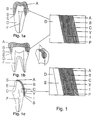
- Fig. 1 shows cross sections of natural teeth one with an artificial tooth crown (Fig.1a) one with an inlay (Fig. 1b), and one with a veneer (Fig. 1c).
- A dental porcelain
- B core in densely sintered ceramic
- Y the outer surface of the core
- I the inner surface of the core
- C cement
- P the prepared surface of the tooth
- S the preparation border
- E enamel
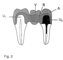
- Fig. 2 shows a cross section of a bridge, which is cemented on two supporting teeth.
- These supporting teeth can have a vital abutment (U1) or an artificial abutment (U2) manufactured in a dental alloy, ceramic material or a strengthened polymer.
- the bridge in Fig. 2 contains two artificial dental crowns according to Fig. 1a and with a pontic (V) between as replacement for a lost tooth.
- the bridge contains a core (B) with dental porcelain (A).
- a bridge can contain more supporting teeth and also more pontics in between.
- the supporting teeth can also be prepared for inlays or veneers. Veneers can be made both buccaly and lingually.
- the supporting teeth can also be implants with artificial abutments.
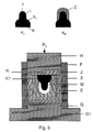
- Fig. 3 shows a cross section of an example of a press for individual cores for tooth crowns.
- K1 is a model of a preparation for a tooth crown enlarged considering the sintering shrinkage.
- S is the preparation border
- T the top of the model
- R its bottom and L the surface, which is the enlarged surface of the preparation (P).
- K2 consists of K1 with a coping of e.g. wax and Z is the outer surface of this coping.
- F is a tube.
- G1 is a plate with a cylinder G, which fits into F.
- H is a cylinder, which also fits into F.
- H, F, E, G and G1 can be made in e.g. metallic material E is made in a viscous elastic material as well as J and X, which are impressions of K2, M is a cavity with space for ceramic powder.
- K1 has been placed in X and P k is the force with which H is pressed against G.
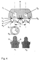
- Fig. 4 shows a cross section of an impression of two supporting teeth prepared for crowns and the gingiva between the teeth.
- c1 and c2 are the impressions of the preparations of the supporting teeth in a, which is the impression material.
- b1 and b2 are two parallel tubes firmly united to each other with b3.
- the inner surfaces of bland b2 consist of two cylinder surfaces with radii r1 and r2. They are connected with e1-e2.
- w is the angle between the parts of b1 and b2 with radius r1 and the surface with the cross section e1-e2.
- q1 and q2 are grooves in the part of the tubes b1 and b2 with radius r2.
- h is the distance between the parallel central axes of b1 and b2.
- n1 and n2 are models of c1 and c2 made by pouring model material e.g. plaster in the tubes b1 and b2 and c1 and c2.
- Fig. 5 shows N1 and N2 which are enlarged (compensated for the shrinking during sintering) models of n1 and n2.
- f is a fixture with the holes g1 and g2, manufactured so that the distance H between the central axes of g1 and g2 is h when enlarged considering the sintering shrinkage as well as the inner shape of the holes g1 and g2, which are enlarged from the inner surface of the tubes b1 and b2.
- Q1 and Q2 are the enlarged grooves q1 and q2.
- Fig. 6 shows N1and N2 placed in the fixture f.
- X1 is a tool made in a rubber material and M1 is a cavity.
- artificial tooth crowns, inlays, veneers or bridges are made as a core in densely sintered ceramic (B) with dental porcelain fired to the surface (A).
- the tooth restorations are fixed to the prepared surfaces(P) by e.g. cementing, as well as the bridge to the abutments U1 and U2.
- the thin layer of cement (C) connects the prepared cavity walls (P) with that part of the surface of the inner surface of the core (I), which has been made so that this surface (D) fits with great precision to the prepared surface (P).
- the layer of cement can have a thickness ⁇ 100 ⁇ m, preferably 25-50 ⁇ m.
- the cementing of the restorations can be made with e.g. zinc phosphate cement, glass-ionomer cement or some resin cement.
- silane treat the inner surfaces (I) of the cores of the constructions, which will be joined with the prepared surfaces (P) of the tooth structure as well as it also can be advantageous to etch and treat the prepared surfaces (P) with a bonding resin before the cementation.
- the ceramic powder can be made by several for the expert well known methods. Traditional powder metallurgical technique can be used, where the different components are mixed and ground under dry or wet conditions with water or an inorganic solvent (e.g. alcohols) as grinding liquid. To the ceramic slurry lubricants or other organic binders depending on the choice of forming method are added, when needed at suitable time in the process.
- Traditional powder metallurgical technique can be used, where the different components are mixed and ground under dry or wet conditions with water or an inorganic solvent (e.g. alcohols) as grinding liquid.
- an inorganic solvent e.g. alcohols
- the ceramic base material in the core preferably comprises one or several biocompatible oxides, with additives of carbides and nitrides with or without binders.
- biocompatible oxides which can form base matrix for the ceramic body, are Al2O3, TiO2, MgO, ZrO2, and ZrO2 with additives of smaller amounts of up to 10 mole-% of Y2O3 or MgO (partly or totally stabilized ZrO2).
- Additives can be present as particles with a size of ⁇ 25 ⁇ m, preferably ⁇ 10 ⁇ m and/or as whiskers (hair shaped single crystals) with a length of >10 ⁇ m, preferably >25 ⁇ m and a length to diameter ratio >5, preferably >10 and/or fibers (polycrystalline) with a diameter >10 ⁇ m and/or as single crystal platelets with an approximate diameter of 5-50 ⁇ m and a thickness of 1-10 ⁇ m.
- the amount of whiskers, fibers and/or platelets should not exceed 60 volume%.
- the ceramic material comprises >50% Al2O3 with additives of conventional sintering aids.
- additives of conventional sintering aids In order to increase the strength ⁇ 25 weight %, preferably 3-12 weight % of ZrO2, and/or 5-40 weight %, preferably 10-30 weight % of SiC-, TiN- or ZrN-whiskers can be added. It is important that the ceramic material is sintered to closed porosity, which for an oxide material means at least 95% of theoretical density, but in order to ensure good mechanical strength the material should preferably have a density over 98%, densities over 99.5% giving the best strength.
- Additives e.g. 0.1-1 weight % of TiN and/or ZrN will give Al2O3 based cores a faint yellow shade. Fe2O3 gives a yellow brown shade and MnO2 gives a rose-coloured shade.
- additives which give non-estetic effects, should not be used.
- artificial ceramic tooth crowns, inlays, veneers and bridges now exist characterized in that they are made from a ready to press powder with additions of lubricants and/or other organic binders.
- the powder When manufacturing the core of a individual tooth crown the powder is compacted against the body K1 to a core, which after sintering to full density fits to the prepared surface and with a desired wall thickness.
- the enlarged model (K1) the sintering shrinkage has to be considered.
- the surface (L) must be enlarged in order to have the desired inner geometrical shape (I) of the green body, which fits against the prepared surface (P) after subsequent sintering process.
- the desired shape of the gap between the tooth crown and the prepared tooth for cementing the crown to the prepared tooth must also be considered.
- the size of this gap can be calculated e.g. to be as small as possible at the preparation border.
- the cores of the tooth crowns are manufactured by cold isostatic compaction, uniaxial pressing, slip casting, pressure casting, injection moulding or by compacting the powder in another way, preferably by a cold isostatic technique against a body (K1), which is shown in Fig. 3.
- K1 has a surface (L), which is uniform with the surface (P) of the prepared tooth, on which the tooth crown or the veneer will fit.
- the body (K1) is manufactured by registering the prepared surface (P) or an artificial abutment directly in the mouth or from a model e.g. in plaster by a three dimensional mechanical or optical method. The registered surface is reproduced in an enlarged size (L) e.g. with a computer controlled milling machine.
- the enlargement is calculated from the shrinkage of the ceramic material during sintering to full density.
- the gap for cement is considered. It is important that the preparation border S respectively S1 are evident.
- the body (K1) is given such a shape that its surfaces converge to the occlusal part of the preparation.
- the outer surface can be e.g. cylindrical.
- the body (K1) can be manufactured in e.g. metallic material, graphite, polymers et cetera.
- the surface (L) of the body K1 is manufactured with a computer controlled milling machine, which enlarges the registered tooth surface, will after compacting the powder against this surface (L) and sintering to full density give the inner shape of the core (I).
- the outer surface (Y) of the core is formed as follows: A body (K2), which is shown in Fig. 3 is milled with a computer controlled milling machine from registered data from the prepared surface (P) of the registered tooth or the surface of the artificial abutment.
- K2 contains the outer surface Z.
- the outer surface Z can be formed by forming a coping in any easily moldable material e.g. wax or a material, which easily can be formed against the body K1.
- the outer surface (Z) of this second body (K2) or (K1) with a coping in e.g. wax is used to form the outer shape (Y) of the core.
- An impression (X) is made from the body (K2), or K1 with a coping in e.g. wax in some viscous elastic material e.g. a silicone.
- the compaction of the powder can be made with tool according to Fig. 3.
- This tool contains the impression X.
- K1 fits into X from the bottom (R) to the preparation border S. Between the surface(L) of K1 and X there is a cavity M.
- the impression X has such a shape as to fit into a body E, which can contain a viscous elastic material.
- the body E is placed into a tube (F), which is put on G, which is a part of G1.
- the cylinder (H) with the same diameter as G is put into the tube (F) from the top.
- a lid (J) placed in the same material as E.
- the manufacture of an individual core to a tooth crown can be made in the following way:
- the pressing tool is put together with the tube F on the cylinder G.
- E with X is put into the tube F.
- Ready to press powder is filled into the cavity M and the body K1 is fit into X.
- K1 fits into the impression X from the preparation border S1 or just below and to the bottom R of the body K1.
- the lid J and the cylinder H are placed and the whole tool according to Fig. 3 is put into a press e.g. a uniaxial hydraulic press.
- a press e.g. a uniaxial hydraulic press.
- the cylinder H is pressed with the force P k in the tube F against the cylinder G in contact with the lid J and the powder is compacted against the body K1.
- the wall thickness of the green body is determined by the amount of powder put into M. After the pressing the green body is adjusted at the preparation border (S1) and the wall thickness is controlled and adjusted before the sintering to full density.
- the wall thickness can be 0.5 mm, however, on certain places wall thicknesses >0.5 mm can be needed in order to strengthen marginal ridges or for replacement of removed fillings.
- the core (B) is adjusted against the preparation border (S) of the plaster model in order to fit the surface I of the core against the surface P of the prepared tooth or against the artificial abutment. Finally dental porcelain can be fired to the core for the manufacture of a tooth crown.
- a veneer can be manufactured in the same way as above.
- a core (B) of an inlay can also be manufactured by registering the surface (P) prepared for an inlay by a three dimensional mechanical or optical method.
- the registered tooth surface is reproduced in an enlarged size in a metal, graphite or a polymer e.g. with a computer controlled milling machine, which enlarges the preparation.
- the enlargement is calculated from the shrinkage of the ceramic material during sintering to full density and with a reduction for the cement.
- An impression (X) (Fig. 3) can be manufactured in the same way, as for a core of a tooth crown. Before the manufacturing of the impression X for an inlay the enlarged preparation is overfilled with e.g. wax.
- This enlarged model with the filled preparation cavity is used for the manufacture of the impression X in some viscous elastic material e.g. a silicone.
- This impression is placed in a press in the same way as described in Fig. 3 after the ceramic powder has been put in the cavity between the enlarged model and the impression X.
- the green body is removed.
- the preparation must not contain any undercuts. The green body is adjusted against the preparation border and space can be given if dental porcelain will be fired to the outer surfaces of the inlay, that means the surfaces which are not cemented against the prepared surfaces of the tooth. After the sintering of the core some adjustment by grinding or polishing can be needed.
- a bridge can be manufactured by starting with the registration of the surfaces of the prepared tooth and the soft tissue in between by a three dimensional mechanical or optical method. It is important to register the mutual relationship of the supporting teeth which can be done in the following way.
- An impression is made with conventional impression technique e.g. with a silicone impression material. This impression is cast in e.g. plaster. From this model or directly in the mouth the prepared teeth and the jaw in between is registered by a three dimensional mechanical or optical method.
- the prepared teeth and the tooth free jaw in between are reproduced in an enlarged size with e.g. a computer controlled milling machine.
- the enlargement is calculated from the shrinkage of the ceramic material during sintering to full density and with an additional space for the cement.
- the material in the enlarged models can be e.g. graphite, metal or a polymer.
- An impression as shown in Fig. 4 is made from the supporting teeth and the tissue in between with a conventional impression technique e.g. with an impression material in e.g. a silicone material (A).
- Fig. 4 shows a cross section of an impression.
- the tubes b1 and b2 are pressed into the impression material (a).
- the tubes can also be fixed to the impression with e.g. sticky wax.
- the tubes b1 and b2 can e.g.
- the tubes b1 and b2 have parallel longitudinal axes and surround the impressions (c1 and c2) of the preparations of the supporting teeth in the impression material (a).
- the tubes b1 and b2 are fixed to each other with b3.
- the impressions (c1 and c2) are poured out in e.g. plaster, which gives the models (n1 and n2) shown in Fig. 4.
- the models n1 and n2 are registered with a three dimensional mechanical or optical method and are reproduced in an enlarged size with e.g. a computer controlled milling machine.
- the enlargement is calculated from the shrinkage of the ceramic material during sintering to full density and with an additional space for the cement above the preparation border (S1) of the models N1 and N2.
- the material of N1 and N2 can be e.g. metallic material, graphite or a polymer.
- These enlarged models (N 1 and N2) are put into a fixture f as shown in Fig. 5.
- the fixture f contains a plate in e.g. a metal, which has two holes g1 and g2.
- These holes have a geometry, which is uniform with the internal surfaces of the tubes b1 and b2 and enlarged with the same enlargement factor considering the sintering shrinkage for the current ceramic powder.
- the distance (H) between the longitudinal axes of the holes is enlarged considering the sintering shrinkage of the ceramic material.
- FIG. 6 is an outline figure of the impression X.
- the models N1 and N2 put in the fixture f are placed in the impression X, manufactured in the same way as has been described for cores of single tooth crowns.
- the empty space M1 which surrounds N1 and N2 ceramic powder is placed and the tool is put in a pressing tool according to Fig. 3 and a compacting pressure P k is applied. The ceramic powder will be compacted against N1 and N2 and against the part of the fixture, which is situated between N1 and N2.
- the green body is removed and the copings are adjusted at the preparation border and where the wall thickness needs reduction.
- the beam can be formed with e.g. a milling cutter in a hand piece of a dental technician in order to give it a suitable form as a substructure of pontics.
- the core is sintered to full density. After the sintering some adjustment can be needed before the firing of dental porcelain to the core to have a bridge according to Fig. 2.
- the manufacturing of a bridge the mutual relationship of the supporting teeth can be maintained after the enlargement in many other ways e.g. before the impression (a) is cast some markers are placed in the impression in such a way that they give impressions in the different parts (the supporting teeth and the jaw in between) into which the plaster model will be divided by sawing.
- the impressions of the markers in combination with enlarged markers can be used to have the mutual relationship of the supporting teeth after the enlargement.
- a bridge can also be manufactured, which is based on supporting teeth with preparations for a veneer on the buccal surface or a preparation on the lingual surface for a lingual plate.
- the manufacture of such a bridge can be made in the same way as has been described for a bridge with supporting teeth prepared for full crowns.
- a bridge can also be made for supporting teeth prepared for inlays.
- the manufacture of compaction tool and the compaction are made in the same way as described for a bridge with supporting teeth prepared for full crowns.
- the supporting teeth can have different types of preparations.
- a bridge based on supporting teeth prepared for inlays can also be made in densely sintered, ceramic material by starting from e.g. a plaster model of the prepared teeth and the jaw between.
- a beam can be made by using a light hardened polymer filled into the inlay preparations and connecting the preparations of the bridge. Before the hardening of the polymer it is given such a shape that the inlays and the beam between have the desired form. After the light hardening of the polymer bridge it is removed and is registered by a three dimensional mechanical or optical method and reproduced in an enlarged size to a green body or a presintered ceramic body with e.g. a computer controlled milling machine. The enlargement is calculated from the shrinkage of the ceramic material during sintering to full density.
- Another way of manufacturing a densely sintered shell which after sintering to full density fits to a prepared tooth, is to make an impression of the enlarged body K1 considering the sintering shrinkage and an additional space for the cement according to Fig. 3.
- This impression is cast in plaster and a model K3 in plaster is obtained from K1.
- An impression (X) is made according to Fig. 3.
- K3 ceramic powder is compacted with e.g. the compaction tool described in Fig. 3.
- the green body is presintered on the plaster model.
- Alumina is presintered at 800°C-1100°C. During the presintering water is released from the plaster, which shrinks about 15%.
- the ceramic material shrinks much less and the presintered core can easily be removed, adjusted and sintered to full density.
- a densely sintered shell which after sintering to full density fits on a prepared tooth, is to make a slurry of ceramic powder mixed and ground under wet conditions with water or an inorganic solvent (e.g. alcohols) as grinding liquid.
- an inorganic solvent e.g. alcohols
- To the ceramic slurry lubricants or other organic binders are added.
- On the enlarged plaster model K3 of the prepared tooth the slurry of the ceramic powder is placed in some way e.g. with a brush from the preparation border (S1) to the top (T).
- the plaster model of K1 (K3) can also be dipped into a slurry of the ceramic powder.
- a suction cup can be applied to the bottom surface (R) and by the suction cup a negative pressure is applied during the dipping of the body K3 into the slurry as described in the Swedish patent application no. 9004134-4.
- the ceramic particles will be packed against the plaster model, when this model absorbs the water from the slurry.
- the ceramic powder is compacted against the plaster model and the body compacted in this way can be adjusted at the preparation border S1 and adjusted to desired shape and shell thickness of the core.
- the green body is presintered on the plaster model.
- the presintered body will be too big for the plaster model and can be removed for any adjustment and sintering to full density.
- plaster other porous materials can be used provided that they can be used as sintering support during the presintering.
- Bridges can be manufactured with above described slip casting method by making an impression from N1 and N2 in the fixture f (Fig. 5) and cast in e.g. plaster.
- a support for the slurry to make the substructure for the pontics is built up with e.g. wax on the fixture between N1 and N2.
- An impression is made of the fixture with the support (N1 and N2) for the pontics, which is cast in plaster.
- the plaster model is fixed to a plate in some ceramic material and is divided into three parts (N1, pontic and N2). The three parts have the same mutual relationship as before the separation.
- a slurry is placed in the same manner as was described for cores for single tooth crowns.
- the separated and fixed plaster model with the ceramic slurry is presintered and the presintered bridge core can, if needed, be adjusted before the sintering to full density.
- Another way of manufacturing a core of a bridge is to compact ceramic powder with a tool shown in Fig. 6 against N1 and N2 in the fixture f according to Fig. 5 or against a plaster model according to Fig.5 fixed and separated into three parts.
- the tool is placed in a compaction tool similar to that shown in Fig. 3 after the ceramic powder has been placed into M1.
- the green body manufactured in this way is adjusted before the presintering. After the presintering the body can have any adjustment before the sintering to full density in a known way.
Abstract
Description
- This invention relates to powder metallurgical manufacturing methods for making accurately shaped artificial tooth restorations with an individually manufactured core of a densely sintered, high strength ceramic material, which fits against prepared tooth surfaces or artificial abutments. On these cores dental porcelain can be fired to tooth crowns, inlays, veneers or bridges.
- U.S. 5,080,589 discloses a method of manufacturing copings in densely sintered, high strength ceramic material where the sintering shrinkage is considered. According to this patent the copings are premanufactured, which means that they have in advance given measure.
- U.S. 5,106,303 and the Swedish patent SE 469 057 disclose manufacturing of inlays, onlay crowns and veneers in densely sintered, high strength ceramic material by copy milling a green body or a presintered or sintered body from an impression of the prepared tooth surface and considering the sintering shrinkage.
- The object of the present invention is to provide a rational manufacturing technique for manufacturing tooth crowns, inlays, veneers or bridges in densely sintered, high strength ceramic material by using modern powder metallurgical technique and reading technique.
- The present invention relates to a method of manufacturing with powder metallurgical methods artificial tooth restorations for natural tooth or implants containing an individual core in densely sintered, high strength ceramic material with dental porcelain fired to the surface. The inner surface of the core, which will fit to one or more prepared surfaces or artificial abutments is manufactured by forming a ceramic powder mixture against a surface of a body at which mentioned surface is manufactured by a three dimensional optical or mechanical reading method, register the prepared surfaces of the prepared tooth or artificial abutments and their mutual relationship, either directly in the mouth or on a model in e.g. plaster after which the registered surfaces are reproduced in an enlarged size e.g. by using a computer controlled milling machine at which the enlargement is calculated by considering the shrinkage of the ceramic material during the sintering to full density with the addition of a desired gap for cement.
- Fig. 1 shows cross sections of natural teeth one with an artificial tooth crown (Fig.1a) one with an inlay (Fig. 1b), and one with a veneer (Fig. 1c). In this figure A= dental porcelain, B= core in densely sintered ceramic, Y= the outer surface of the core, I= the inner surface of the core, C= cement, P= the prepared surface of the tooth, S= the preparation border, E= enamel, D= dentin and F= pulp.
- Fig. 2 shows a cross section of a bridge, which is cemented on two supporting teeth. These supporting teeth can have a vital abutment (U₁) or an artificial abutment (U₂) manufactured in a dental alloy, ceramic material or a strengthened polymer. The bridge in Fig. 2 contains two artificial dental crowns according to Fig. 1a and with a pontic (V) between as replacement for a lost tooth. The bridge contains a core (B) with dental porcelain (A). A bridge can contain more supporting teeth and also more pontics in between. The supporting teeth can also be prepared for inlays or veneers. Veneers can be made both buccaly and lingually. The supporting teeth can also be implants with artificial abutments.
- Fig. 3 shows a cross section of an example of a press for individual cores for tooth crowns. K₁ is a model of a preparation for a tooth crown enlarged considering the sintering shrinkage. S is the preparation border, T the top of the model, R its bottom and L the surface, which is the enlarged surface of the preparation (P). K₂ consists of K₁ with a coping of e.g. wax and Z is the outer surface of this coping. F is a tube. G₁ is a plate with a cylinder G, which fits into F. H is a cylinder, which also fits into F. H, F, E, G and G₁ can be made in e.g. metallic material E is made in a viscous elastic material as well as J and X, which are impressions of K₂, M is a cavity with space for ceramic powder. K₁ has been placed in X and Pk is the force with which H is pressed against G.
- Fig. 4 shows a cross section of an impression of two supporting teeth prepared for crowns and the gingiva between the teeth. c₁ and c₂ are the impressions of the preparations of the supporting teeth in a, which is the impression material. b₁ and b₂ are two parallel tubes firmly united to each other with b₃. The inner surfaces of bland b₂ consist of two cylinder surfaces with radii r₁ and r₂. They are connected with e₁-e₂. w is the angle between the parts of b₁ and b₂ with radius r₁ and the surface with the cross section e₁-e₂. q₁ and q₂ are grooves in the part of the tubes b₁ and b₂ with radius r₂. h is the distance between the parallel central axes of b₁ and b₂. n₁ and n₂ are models of c₁ and c₂ made by pouring model material e.g. plaster in the tubes b₁ and b₂ and c₁ and c₂.
- Fig. 5 shows N₁ and N₂ which are enlarged (compensated for the shrinking during sintering) models of n₁ and n₂. f is a fixture with the holes g₁ and g₂, manufactured so that the distance H between the central axes of g₁ and g₂ is h when enlarged considering the sintering shrinkage as well as the inner shape of the holes g₁ and g₂, which are enlarged from the inner surface of the tubes b₁ and b₂. Q₁ and Q₂ are the enlarged grooves q₁ and q₂.
- Fig. 6 shows N₁and N₂ placed in the fixture f. X₁ is a tool made in a rubber material and M₁ is a cavity.
- As can be seen from Fig. 1 and Fig. 2 artificial tooth crowns, inlays, veneers or bridges are made as a core in densely sintered ceramic (B) with dental porcelain fired to the surface (A). The tooth restorations are fixed to the prepared surfaces(P) by e.g. cementing, as well as the bridge to the abutments U₁ and U₂. The thin layer of cement (C) connects the prepared cavity walls (P) with that part of the surface of the inner surface of the core (I), which has been made so that this surface (D) fits with great precision to the prepared surface (P). On the outer surface (Y) of the core (B) dental porcelain can be fired. The layer of cement can have a thickness <100 µm, preferably 25-50 µm. The cementing of the restorations can be made with e.g. zinc phosphate cement, glass-ionomer cement or some resin cement. In the last case it can be an advantage to silane treat the inner surfaces (I) of the cores of the constructions, which will be joined with the prepared surfaces (P) of the tooth structure as well as it also can be advantageous to etch and treat the prepared surfaces (P) with a bonding resin before the cementation.
- The ceramic powder can be made by several for the expert well known methods. Traditional powder metallurgical technique can be used, where the different components are mixed and ground under dry or wet conditions with water or an inorganic solvent (e.g. alcohols) as grinding liquid. To the ceramic slurry lubricants or other organic binders depending on the choice of forming method are added, when needed at suitable time in the process.
- The ceramic base material in the core preferably comprises one or several biocompatible oxides, with additives of carbides and nitrides with or without binders. Examples of biocompatible oxides, which can form base matrix for the ceramic body, are Al₂O₃, TiO₂, MgO, ZrO₂, and ZrO₂ with additives of smaller amounts of up to 10 mole-% of Y₂O₃ or MgO (partly or totally stabilized ZrO₂). Additives can be present as particles with a size of <25 µ m, preferably <10 µm and/or as whiskers (hair shaped single crystals) with a length of >10 µm, preferably >25 µm and a length to diameter ratio >5, preferably >10 and/or fibers (polycrystalline) with a diameter >10 µm and/or as single crystal platelets with an approximate diameter of 5-50 µm and a thickness of 1-10 µm. The amount of whiskers, fibers and/or platelets should not exceed 60 volume%.
- In a preferred embodiment the ceramic material comprises >50% Al₂O₃ with additives of conventional sintering aids. In order to increase the strength <25 weight %, preferably 3-12 weight % of ZrO₂, and/or 5-40 weight %, preferably 10-30 weight % of SiC-, TiN- or ZrN-whiskers can be added. It is important that the ceramic material is sintered to closed porosity, which for an oxide material means at least 95% of theoretical density, but in order to ensure good mechanical strength the material should preferably have a density over 98%, densities over 99.5% giving the best strength.
- In order to get a suitable colour of the core (B) coloured components can be chosen. Additives e.g. 0.1-1 weight % of TiN and/or ZrN will give Al₂O₃ based cores a faint yellow shade. Fe₂O₃ gives a yellow brown shade and MnO₂ gives a rose-coloured shade. Of course, additives, which give non-estetic effects, should not be used.
- According to the invention artificial ceramic tooth crowns, inlays, veneers and bridges now exist characterized in that they are made from a ready to press powder with additions of lubricants and/or other organic binders. When manufacturing the core of a individual tooth crown the powder is compacted against the body K₁ to a core, which after sintering to full density fits to the prepared surface and with a desired wall thickness. When manufacturing the enlarged model (K₁) the sintering shrinkage has to be considered. The surface (L) must be enlarged in order to have the desired inner geometrical shape (I) of the green body, which fits against the prepared surface (P) after subsequent sintering process. The desired shape of the gap between the tooth crown and the prepared tooth for cementing the crown to the prepared tooth must also be considered. The size of this gap can be calculated e.g. to be as small as possible at the preparation border.
- The cores of the tooth crowns are manufactured by cold isostatic compaction, uniaxial pressing, slip casting, pressure casting, injection moulding or by compacting the powder in another way, preferably by a cold isostatic technique against a body (K₁), which is shown in Fig. 3. K₁ has a surface (L), which is uniform with the surface (P) of the prepared tooth, on which the tooth crown or the veneer will fit. The body (K₁) is manufactured by registering the prepared surface (P) or an artificial abutment directly in the mouth or from a model e.g. in plaster by a three dimensional mechanical or optical method. The registered surface is reproduced in an enlarged size (L) e.g. with a computer controlled milling machine. The enlargement is calculated from the shrinkage of the ceramic material during sintering to full density. When calculating the shape of K₁ the gap for cement is considered. It is important that the preparation border S respectively S₁ are evident. Below the preparation border S₁ between S₁ and the bottom R the body (K₁) is given such a shape that its surfaces converge to the occlusal part of the preparation. At the bottom (R) the outer surface can be e.g. cylindrical. The body (K₁) can be manufactured in e.g. metallic material, graphite, polymers et cetera. K₁ will have such a size that the inner surface of the green body (the impression of L) after shrinkage during sintering to full density receives the inner surface I, which has desired fit against the prepared tooth surface (P) or to an artificial abutment. The surface (L) of the body K₁ is manufactured with a computer controlled milling machine, which enlarges the registered tooth surface, will after compacting the powder against this surface (L) and sintering to full density give the inner shape of the core (I). During compaction the outer surface (Y) of the core is formed as follows: A body (K₂), which is shown in Fig. 3 is milled with a computer controlled milling machine from registered data from the prepared surface (P) of the registered tooth or the surface of the artificial abutment. This body (K₂) is enlarged considering the sintering shrinkage in the same way as the body K₁ and with an additional material from the preparation border or just below. K₂ contains the outer surface Z. The outer surface Z can be formed by forming a coping in any easily moldable material e.g. wax or a material, which easily can be formed against the body K₁. The outer surface (Z) of this second body (K₂) or (K₁) with a coping in e.g. wax is used to form the outer shape (Y) of the core. An impression (X) is made from the body (K₂), or K₁ with a coping in e.g. wax in some viscous elastic material e.g. a silicone. The compaction of the powder can be made with tool according to Fig. 3. This tool contains the impression X. K₁ fits into X from the bottom (R) to the preparation border S. Between the surface(L) of K₁ and X there is a cavity M. The impression X has such a shape as to fit into a body E, which can contain a viscous elastic material. The body E is placed into a tube (F), which is put on G, which is a part of G₁. The cylinder (H) with the same diameter as G is put into the tube (F) from the top. Between H and E containing X is a lid (J) placed in the same material as E.
- The manufacture of an individual core to a tooth crown can be made in the following way: The pressing tool is put together with the tube F on the cylinder G. E with X is put into the tube F. Ready to press powder is filled into the cavity M and the body K₁ is fit into X. K₁ fits into the impression X from the preparation border S₁ or just below and to the bottom R of the body K₁. Finally, the lid J and the cylinder H are placed and the whole tool according to Fig. 3 is put into a press e.g. a uniaxial hydraulic press. During the compaction of the powder the cylinder H is pressed with the force Pk in the tube F against the cylinder G in contact with the lid J and the powder is compacted against the body K₁. After the compaction H, J and K₁ are removed and the compacted shell, which in some cases can be attached to K₁. K must not contain any undercuts. The wall thickness of the green body is determined by the amount of powder put into M. After the pressing the green body is adjusted at the preparation border (S₁) and the wall thickness is controlled and adjusted before the sintering to full density. The wall thickness can be 0.5 mm, however, on certain places wall thicknesses >0.5 mm can be needed in order to strengthen marginal ridges or for replacement of removed fillings. After sintering to full density the core (B) is adjusted against the preparation border (S) of the plaster model in order to fit the surface I of the core against the surface P of the prepared tooth or against the artificial abutment. Finally dental porcelain can be fired to the core for the manufacture of a tooth crown.
- A veneer can be manufactured in the same way as above.
- A core (B) of an inlay can also be manufactured by registering the surface (P) prepared for an inlay by a three dimensional mechanical or optical method. The registered tooth surface is reproduced in an enlarged size in a metal, graphite or a polymer e.g. with a computer controlled milling machine, which enlarges the preparation. The enlargement is calculated from the shrinkage of the ceramic material during sintering to full density and with a reduction for the cement. An impression (X) (Fig. 3) can be manufactured in the same way, as for a core of a tooth crown. Before the manufacturing of the impression X for an inlay the enlarged preparation is overfilled with e.g. wax. This enlarged model with the filled preparation cavity is used for the manufacture of the impression X in some viscous elastic material e.g. a silicone. This impression is placed in a press in the same way as described in Fig. 3 after the ceramic powder has been put in the cavity between the enlarged model and the impression X. After the compaction the green body is removed. In order to be able to remove the green body without destroying it, the preparation must not contain any undercuts. The green body is adjusted against the preparation border and space can be given if dental porcelain will be fired to the outer surfaces of the inlay, that means the surfaces which are not cemented against the prepared surfaces of the tooth. After the sintering of the core some adjustment by grinding or polishing can be needed.
- When manufacturing a bridge it is important to maintain the mutual relationship after the enlargement. A bridge can be manufactured by starting with the registration of the surfaces of the prepared tooth and the soft tissue in between by a three dimensional mechanical or optical method. It is important to register the mutual relationship of the supporting teeth which can be done in the following way. An impression is made with conventional impression technique e.g. with a silicone impression material. This impression is cast in e.g. plaster. From this model or directly in the mouth the prepared teeth and the jaw in between is registered by a three dimensional mechanical or optical method. The prepared teeth and the tooth free jaw in between are reproduced in an enlarged size with e.g. a computer controlled milling machine. The enlargement is calculated from the shrinkage of the ceramic material during sintering to full density and with an additional space for the cement. The material in the enlarged models can be e.g. graphite, metal or a polymer.
- An enlarged model which considers the whole situation can also be made in the following way. An impression as shown in Fig. 4 is made from the supporting teeth and the tissue in between with a conventional impression technique e.g. with an impression material in e.g. a silicone material (A). Fig. 4 shows a cross section of an impression. The tubes b₁ and b₂ are pressed into the impression material (a). In order not to deform the impression of the preparations that part of the tubes pressed into the impression material can e.g. have a chamfered edge. The tubes can also be fixed to the impression with e.g. sticky wax. The tubes b₁ and b₂ can e.g. have elliptic or circular cross section with grooves (q₁ and q₂) in the longitudinal axis in the internal surfaces of the tubes, and a step e₁-e₂, is clear from a cross section parallel with the longitudinal axes. The tubes b₁ and b₂ have parallel longitudinal axes and surround the impressions (c₁ and c₂) of the preparations of the supporting teeth in the impression material (a). The tubes b₁ and b₂ are fixed to each other with b₃. The impressions (c₁ and c₂) are poured out in e.g. plaster, which gives the models (n₁ and n₂) shown in Fig. 4. The models n₁ and n₂ are registered with a three dimensional mechanical or optical method and are reproduced in an enlarged size with e.g. a computer controlled milling machine. The enlargement is calculated from the shrinkage of the ceramic material during sintering to full density and with an additional space for the cement above the preparation border (S₁) of the models N₁ and N₂. The material of N₁ and N₂ can be e.g. metallic material, graphite or a polymer. These enlarged models (N ₁ and N₂) are put into a fixture f as shown in Fig. 5. The fixture f contains a plate in e.g. a metal, which has two holes g₁ and g₂. These holes have a geometry, which is uniform with the internal surfaces of the tubes b₁ and b₂ and enlarged with the same enlargement factor considering the sintering shrinkage for the current ceramic powder. The distance (H) between the longitudinal axes of the holes is enlarged considering the sintering shrinkage of the ceramic material. By placing the enlarged models N₁ and N₂ in the fixture f an enlarged model of the prepared supporting teeth and their mutual relationship is made. The step E₁-E₂ and the grooves Q₁ and Q₂ and the distance (H) give the mutual relationship of the enlarged preparations. The manufacturing of the tool for compacting the ceramic powder to the bridge is made in a similar way as is shown in Fig. 3. An impression X has to be made which gives space for powder to a beam which connects the copings, which after the compaction will fit the enlarged preparations N₁ and N₂. Fig. 6 is an outline figure of the impression X. In Fig. 6 the models N₁ and N₂ put in the fixture f are placed in the impression X, manufactured in the same way as has been described for cores of single tooth crowns. In the empty space M₁, which surrounds N₁ and N₂, ceramic powder is placed and the tool is put in a pressing tool according to Fig. 3 and a compacting pressure Pk is applied. The ceramic powder will be compacted against N₁ and N₂ and against the part of the fixture, which is situated between N₁ and N₂. The green body is removed and the copings are adjusted at the preparation border and where the wall thickness needs reduction. The beam can be formed with e.g. a milling cutter in a hand piece of a dental technician in order to give it a suitable form as a substructure of pontics. The core is sintered to full density. After the sintering some adjustment can be needed before the firing of dental porcelain to the core to have a bridge according to Fig. 2.
- The manufacturing of a bridge the mutual relationship of the supporting teeth can be maintained after the enlargement in many other ways e.g. before the impression (a) is cast some markers are placed in the impression in such a way that they give impressions in the different parts (the supporting teeth and the jaw in between) into which the plaster model will be divided by sawing. The impressions of the markers in combination with enlarged markers can be used to have the mutual relationship of the supporting teeth after the enlargement.
- A bridge can also be manufactured, which is based on supporting teeth with preparations for a veneer on the buccal surface or a preparation on the lingual surface for a lingual plate. The manufacture of such a bridge can be made in the same way as has been described for a bridge with supporting teeth prepared for full crowns.
- A bridge can also be made for supporting teeth prepared for inlays. In order to have the mutual relationship between the supporting teeth in the enlarged model considering the sintering shrinkage, the manufacture of compaction tool and the compaction are made in the same way as described for a bridge with supporting teeth prepared for full crowns. The supporting teeth can have different types of preparations.
- A bridge based on supporting teeth prepared for inlays can also be made in densely sintered, ceramic material by starting from e.g. a plaster model of the prepared teeth and the jaw between. A beam can be made by using a light hardened polymer filled into the inlay preparations and connecting the preparations of the bridge. Before the hardening of the polymer it is given such a shape that the inlays and the beam between have the desired form. After the light hardening of the polymer bridge it is removed and is registered by a three dimensional mechanical or optical method and reproduced in an enlarged size to a green body or a presintered ceramic body with e.g. a computer controlled milling machine. The enlargement is calculated from the shrinkage of the ceramic material during sintering to full density.
- Another way of manufacturing a densely sintered shell, which after sintering to full density fits to a prepared tooth, is to make an impression of the enlarged body K₁ considering the sintering shrinkage and an additional space for the cement according to Fig. 3. This impression is cast in plaster and a model K₃ in plaster is obtained from K₁. An impression (X) is made according to Fig. 3. Against K₃ ceramic powder is compacted with e.g. the compaction tool described in Fig. 3. The green body is presintered on the plaster model. Alumina is presintered at 800°C-1100°C. During the presintering water is released from the plaster, which shrinks about 15%. The ceramic material shrinks much less and the presintered core can easily be removed, adjusted and sintered to full density.
- Further, another way of manufacturing a densely sintered shell, which after sintering to full density fits on a prepared tooth, is to make a slurry of ceramic powder mixed and ground under wet conditions with water or an inorganic solvent (e.g. alcohols) as grinding liquid. To the ceramic slurry lubricants or other organic binders are added. On the enlarged plaster model K₃ of the prepared tooth the slurry of the ceramic powder is placed in some way e.g. with a brush from the preparation border (S₁) to the top (T). The plaster model of K₁ (K₃) can also be dipped into a slurry of the ceramic powder. In order to have an optimal compaction of the powder, a suction cup can be applied to the bottom surface (R) and by the suction cup a negative pressure is applied during the dipping of the body K₃ into the slurry as described in the Swedish patent application no. 9004134-4. The ceramic particles will be packed against the plaster model, when this model absorbs the water from the slurry. In this way the ceramic powder is compacted against the plaster model and the body compacted in this way can be adjusted at the preparation border S₁ and adjusted to desired shape and shell thickness of the core. The green body is presintered on the plaster model. The presintered body will be too big for the plaster model and can be removed for any adjustment and sintering to full density. Instead of plaster other porous materials can be used provided that they can be used as sintering support during the presintering.
- Bridges can be manufactured with above described slip casting method by making an impression from N₁ and N₂ in the fixture f (Fig. 5) and cast in e.g. plaster. Before the impression is made a support for the slurry to make the substructure for the pontics is built up with e.g. wax on the fixture between N₁ and N₂. An impression is made of the fixture with the support (N₁ and N₂) for the pontics, which is cast in plaster. The plaster model is fixed to a plate in some ceramic material and is divided into three parts (N₁, pontic and N₂). The three parts have the same mutual relationship as before the separation. Against the plaster model a slurry is placed in the same manner as was described for cores for single tooth crowns. The separated and fixed plaster model with the ceramic slurry is presintered and the presintered bridge core can, if needed, be adjusted before the sintering to full density.
- Another way of manufacturing a core of a bridge is to compact ceramic powder with a tool shown in Fig. 6 against N₁ and N₂ in the fixture f according to Fig. 5 or against a plaster model according to Fig.5 fixed and separated into three parts. The tool is placed in a compaction tool similar to that shown in Fig. 3 after the ceramic powder has been placed into M₁. The green body manufactured in this way is adjusted before the presintering. After the presintering the body can have any adjustment before the sintering to full density in a known way.
Claims (7)
- Method of manufacturing artificial tooth restorations comprising a ceramic densely sintered, high strength individual core (B) with dental porcelain (A) by powder metallurgical manufacturing methods characterized in that the inner surface (I) of the core (B), which will fit against one or more prepared tooth surfaces (P) or artificial abutments are manufactured by forming a ceramic powder mixture against a surface of a body at which this mentioned surface is manufactured by registering the surfaces of the prepared teeth or artificial abutments and their mutual relationship with a three dimensional optical or mechanical reading method directly in the mouth or on a model in e.g. plaster after which the registered surfaces are reproduced in an enlarged size e.g. with a computer controlled milling machine at which the enlargement is calculated from the shrinkage of the ceramic material during sintering to full density and considering the gap for cement.
- Method according to claim 1 characterized in that the outer surface Y of the core is dry pressed close to desired size against the enlarged preparations with the help of an impression in some viscous elastic material.
- Method according to claims 1 and 2 characterized in that the core is made by a dry pressing against a e.g. plaster model of the enlarged preparations, after which the core is presintered on the plaster model.
- Method according to claim 1 characterized in that the core in manufactured by slip casting against e.g. a plaster model of the enlarged preparations, after which the core is presintered on the plaster model.
- Method according to claims 1, 2, 3 and 4 characterized in that the core consists of high strength densely sintered, ceramic material with a relative density of > 99%.
- Method according to claim 5 characterized in that the ceramic material in the core is based on one or more of the oxides Al₂O₃, TiO₂, MgO, ZrO₂ or ZrO₂ with up to 25 mole% Y₂O₃ or MgO.
- Method according to claims 5 and 6 characterized in that the core material also comprises whiskers and/or particles of SiC, TiN, ZrO₂ and/or ZrN.
Applications Claiming Priority (2)
| Application Number | Priority Date | Filing Date | Title |
|---|---|---|---|
| SE9201927 | 1992-06-23 | ||
| SE9201927A SE470346B (en) | 1992-06-23 | 1992-06-23 | Method for making ceramic artificial tooth restorations |
Publications (3)
| Publication Number | Publication Date |
|---|---|
| EP0580565A2 true EP0580565A2 (en) | 1994-01-26 |
| EP0580565A3 EP0580565A3 (en) | 1995-01-11 |
| EP0580565B1 EP0580565B1 (en) | 1998-08-26 |
Family
ID=20386580
Family Applications (1)
| Application Number | Title | Priority Date | Filing Date |
|---|---|---|---|
| EP93850137A Expired - Lifetime EP0580565B1 (en) | 1992-06-23 | 1993-06-21 | Method of manufacturing ceramic artificial tooth restorations |
Country Status (9)
| Country | Link |
|---|---|
| US (1) | US5342201A (en) |
| EP (1) | EP0580565B1 (en) |
| AT (1) | ATE170069T1 (en) |
| DE (1) | DE69320563T2 (en) |
| DK (1) | DK0580565T3 (en) |
| ES (1) | ES2119881T3 (en) |
| FI (1) | FI932910A (en) |
| NO (1) | NO306927B1 (en) |
| SE (1) | SE470346B (en) |
Cited By (16)
| Publication number | Priority date | Publication date | Assignee | Title |
|---|---|---|---|---|
| WO1996023481A1 (en) * | 1995-02-05 | 1996-08-08 | Rainer Hahn | Tooth restoration and prosthesis component made from ceramic material and a method of manufacturing the same. |
| WO1996029951A3 (en) * | 1995-03-28 | 1996-10-31 | Arnold Wohlwend | Process for manufacturing prosthetic dental reconstructions |
| FR2735679A1 (en) * | 1995-06-23 | 1996-12-27 | Aten Dev | Dental prosthesis manufacturing procedure |
| WO1997030654A1 (en) * | 1996-02-22 | 1997-08-28 | Arnold Wohlwend | Implantable tooth replacement, abutment therefor and process for making abutments |
| WO1998027890A1 (en) * | 1996-12-20 | 1998-07-02 | Dentalmatic Technologies Inc. | Method for producing a dental prosthesis |
| WO1999013795A1 (en) * | 1997-09-12 | 1999-03-25 | Sandvik Ab (Publ) | Method for making ceramic artificial dental bridges |
| EP0943296A1 (en) | 1998-03-17 | 1999-09-22 | Eidgenössische Technische Hochschule Zürich | Tooth crowns and/or dental bridges |
| EP0943295A1 (en) * | 1998-03-17 | 1999-09-22 | Eidgenössische Technische Hochschule Zürich | Method for the manufactoring of tooth crowns and/or dental bridges |
| WO2000062705A1 (en) | 1999-04-16 | 2000-10-26 | Kaltenbach & Voigt Gmbh & Co. | Method for producing ceramic medical, dental medical, technical dental and technical parts |
| EP1073400A2 (en) * | 1998-04-23 | 2001-02-07 | George Taub Products and Fusion Company | Method of fabrication of translucent dental restorations |
| WO2001041670A1 (en) * | 1999-12-07 | 2001-06-14 | Inocermic Gesellschaft für innovative Keramik mbH | Method for producing a ceramic dental prosthesis and a high-strength ceramic dental prosthesis produced according thereto |
| WO2003035014A1 (en) * | 2001-10-25 | 2003-05-01 | Vita Zahnfabrik H. Rauter Gmbh & Co. Kg | System for producing a veneering ceramic |
| EP1601511A2 (en) * | 2003-03-07 | 2005-12-07 | Louis A. Serafin | Ceramic manufactures |
| WO2010110650A1 (en) * | 2009-03-25 | 2010-09-30 | Oratio B.V. | Veneered dental restoration with a controlled shade |
| US8986009B2 (en) | 2008-05-08 | 2015-03-24 | Degudent Gmbh | Method for determining 3-D data from at least one prepared maxillary area |
| US9162008B2 (en) | 2003-03-07 | 2015-10-20 | Louis A. Serafin, Jr. | Ceramic manufactures |
Families Citing this family (58)
| Publication number | Priority date | Publication date | Assignee | Title |
|---|---|---|---|---|
| NL9301308A (en) * | 1993-07-26 | 1995-02-16 | Willem Frederick Van Nifterick | Method of securing a dental prosthesis to implants in a patient's jawbone and using means thereof. |
| US5624261A (en) * | 1995-08-09 | 1997-04-29 | Wiedenfeld; Kenneth R. | Composite resin veneer |
| US5788498A (en) * | 1995-12-19 | 1998-08-04 | Ivoclar Ag | Method for manufacturing dental crowns |
| US5827063A (en) * | 1997-04-07 | 1998-10-27 | Greenstein; Jean | Method of making dental restoration employing preforms |
| US6413660B1 (en) * | 1998-06-12 | 2002-07-02 | Jeneric/Pentron, Inc. | High-strength dental restorations |
| US20050127544A1 (en) * | 1998-06-12 | 2005-06-16 | Dmitri Brodkin | High-strength dental restorations |
| US6354836B1 (en) * | 1998-08-20 | 2002-03-12 | Jeneric/Pentron, Inc. | Methods of producing dental restorations using CAD/CAM and manufactures thereof |
| SE512809C2 (en) * | 1998-09-11 | 2000-05-15 | Nobel Biocare Ab | Method, device and use in dental or other human body related product |
| EP1143915B1 (en) * | 1999-01-08 | 2004-12-01 | 3M Innovative Properties Company | Dental mill blanks |
| JP2000256038A (en) * | 1999-03-10 | 2000-09-19 | Gc Corp | Glass powder for glass ionomer cement |
| US6488503B1 (en) | 1999-12-21 | 2002-12-03 | Dentsply Research & Development Corp. | Prosthetic teeth and method of making therefor |
| DE10002921C2 (en) * | 2000-01-25 | 2003-11-20 | Stefan Wolz | Process for the production of all-ceramic bridges |
| US6689202B2 (en) * | 2000-07-21 | 2004-02-10 | Jeneric/Pentron Incorporated | Molds for the manufacture of a dental restoration and methods of making dental restorations |
| JP2003047622A (en) * | 2001-08-03 | 2003-02-18 | Noritake Co Ltd | Dental ceramic frame, manufacture for it and dental prosthesis including the frame |
| SE0200007D0 (en) * | 2002-01-03 | 2002-01-03 | Sandvik Ab | Method of making ceramic artificial dental bridges |
| WO2004087000A1 (en) * | 2003-04-03 | 2004-10-14 | Cadent Ltd. | Method and system for fabricating a dental coping, and a coping fabricated thereby |
| US20040261304A1 (en) * | 2003-06-27 | 2004-12-30 | Edwards Christopher M. | Decorative tiles for attachment to strand meshes |
| SE526679C2 (en) * | 2003-11-12 | 2005-10-25 | Nobel Biocare Ab | Systems and apparatus for the production of dental replacement equipment and such equipment |
| US20150265380A1 (en) * | 2004-02-06 | 2015-09-24 | Zircore, Llc | Companion engineering and manufacturing processes (cemp) to optimize multi-layered zirconia crowns |
| US7690920B2 (en) * | 2005-04-15 | 2010-04-06 | Hunt Peter R | High strength substructure reinforcement for crowns and bridges |
| US20050261795A1 (en) * | 2004-05-21 | 2005-11-24 | Eastman Kodak Company | Method of making ceramic dental restorations |
| US20060194896A1 (en) * | 2004-05-26 | 2006-08-31 | Sun Benjamin J | Low shrinkage dental material and method |
| US7236842B2 (en) * | 2004-12-02 | 2007-06-26 | Cadent Ltd. | System and method for manufacturing a dental prosthesis and a dental prosthesis manufactured thereby |
| WO2006066898A2 (en) * | 2004-12-21 | 2006-06-29 | Johan Feith | Dental implant |
| DE102005023105B4 (en) * | 2005-05-13 | 2012-09-06 | Sirona Dental Systems Gmbh | Process for producing a tooth replacement part and a tooth replacement part produced in this way |
| US8814567B2 (en) | 2005-05-26 | 2014-08-26 | Zimmer Dental, Inc. | Dental implant prosthetic device with improved osseointegration and esthetic features |
| JP5438967B2 (en) | 2005-08-30 | 2014-03-12 | ジマー デンタル, インコーポレイテッド | Dental implant with improved osseointegration features |
| US8562346B2 (en) | 2005-08-30 | 2013-10-22 | Zimmer Dental, Inc. | Dental implant for a jaw with reduced bone volume and improved osseointegration features |
| DE102006013658B4 (en) * | 2006-03-24 | 2008-01-31 | Stefan Wolz | Process for the production of tooth parts by electrophoretic free-forming |
| JP2010513330A (en) * | 2006-12-22 | 2010-04-30 | トーメン メディカル アーゲー | Dental implant and manufacturing method thereof |
| KR100837571B1 (en) | 2007-01-25 | 2008-06-11 | 박수강 | A core for dental and manufacturing method thereof |
| JP2008246131A (en) * | 2007-03-30 | 2008-10-16 | Gc Corp | Method for producing zirconia implant bridge |
| ES2702779T3 (en) * | 2007-06-07 | 2019-03-05 | Nobel Biocare Services Ag | Procedure and sintered product to form a dental bridge |
| ATE507796T1 (en) * | 2007-06-07 | 2011-05-15 | Nobel Biocare Services Ag | METHOD FOR PRODUCING A DENTAL PRODUCT |
| US9149345B2 (en) | 2007-08-30 | 2015-10-06 | Zimmer Dental, Inc. | Multiple root implant |
| EP2072020A1 (en) * | 2007-12-17 | 2009-06-24 | Nobel Biocare Services AG | A method of producing a dental ceramic product |
| US8899982B2 (en) | 2008-07-02 | 2014-12-02 | Zimmer Dental, Inc. | Implant with structure for securing a porous portion |
| US9095396B2 (en) | 2008-07-02 | 2015-08-04 | Zimmer Dental, Inc. | Porous implant with non-porous threads |
| US8231387B2 (en) | 2008-07-02 | 2012-07-31 | Zimmer, Inc. | Porous implant with non-porous threads |
| US8562348B2 (en) | 2008-07-02 | 2013-10-22 | Zimmer Dental, Inc. | Modular implant with secured porous portion |
| EP2172168A1 (en) * | 2008-10-01 | 2010-04-07 | 3M Innovative Properties Company | Dental appliance, process for producing a dental appliance and use thereof |
| US20100114314A1 (en) | 2008-11-06 | 2010-05-06 | Matthew Lomicka | Expandable bone implant |
| EP2263991A1 (en) | 2009-06-19 | 2010-12-22 | Nobel Biocare Services AG | Dental application coating |
| US9707058B2 (en) | 2009-07-10 | 2017-07-18 | Zimmer Dental, Inc. | Patient-specific implants with improved osseointegration |
| EP2482757B1 (en) | 2009-09-30 | 2019-06-26 | 3M Innovative Properties Company | Systems and methods for making layered dental appliances |
| US8721938B2 (en) | 2009-09-30 | 2014-05-13 | 3M Innovative Properties Company | Methods for making layered dental appliances |
| BR112012006947A2 (en) | 2009-09-30 | 2019-09-24 | 3M Innovative Properties Co | Method and system for manufacturing a layered dental part |
| US8602782B2 (en) | 2009-11-24 | 2013-12-10 | Zimmer Dental, Inc. | Porous implant device with improved core |
| US8813364B2 (en) | 2009-12-18 | 2014-08-26 | 3M Innovative Properties Company | Methods for making layered dental appliances |
| KR101169451B1 (en) * | 2010-11-12 | 2012-07-27 | (주)이비아이 | Mold for dental copings and copings produced by the same mold |
| US20120156651A1 (en) * | 2010-12-20 | 2012-06-21 | Levi Jack | Restoration of anterior endodontically treated teeth |
| CN102370525B (en) * | 2011-10-31 | 2013-07-31 | 山东新华医疗器械股份有限公司 | Cantilever type workbench mechanism of processing equipment of full automatic engraving and milling machine |
| WO2015168332A2 (en) * | 2014-04-30 | 2015-11-05 | Osseodyne Surgical Solutions, Llc | Osseointegrative surgical implant |
| EP3238655A1 (en) * | 2016-04-28 | 2017-11-01 | 3M Innovative Properties Company | A method of making a dental restoration |
| AU2016269528B1 (en) * | 2016-12-08 | 2017-09-14 | John Fung | Dental prosthetic moulds and moulding methods |
| WO2019087126A1 (en) * | 2017-11-06 | 2019-05-09 | 3M Innovative Properties Company | Dental crown having a highly retentive coating and methods for making the same |
| EP3610824B1 (en) * | 2018-08-14 | 2021-11-24 | DENTSPLY SIRONA Inc. | Dental prosthesis |
| US20230248487A1 (en) * | 2022-02-10 | 2023-08-10 | Exocad Gmbh | Testing model for testing fitting of a dental restoration |
Citations (6)
| Publication number | Priority date | Publication date | Assignee | Title |
|---|---|---|---|---|
| US4411626A (en) * | 1980-01-31 | 1983-10-25 | Becker Dental-Labor Gmbh | Process and apparatus for preparing a crown portion to be fixed on a tooth |
| US4478580A (en) * | 1982-02-05 | 1984-10-23 | Barrut Luc P | Process and apparatus for treating teeth |
| EP0241384A2 (en) * | 1986-04-11 | 1987-10-14 | Tyszblat Sadoun, Michèle | Method of producing dental prosthesis and prosthesis obtained by this method |
| EP0375647A2 (en) * | 1988-12-20 | 1990-06-27 | Sandvik Aktiebolag | Artificial tooth crown |
| EP0311214B1 (en) * | 1987-10-07 | 1991-05-02 | Elephant Edelmetaal B.V. | A method of making a dental crown for a dental preparation by means of cad-cam system |
| EP0389461B1 (en) * | 1989-03-23 | 1993-11-03 | Sandvik Aktiebolag | Artificial onlay tooth crowns and inlays |
Family Cites Families (2)
| Publication number | Priority date | Publication date | Assignee | Title |
|---|---|---|---|---|
| US4661071A (en) * | 1984-04-03 | 1987-04-28 | Denpac Corp. | Vacuum sintered powder alloy dental prosthetic device and oven to form same |
| US5217375A (en) * | 1989-03-23 | 1993-06-08 | Sandvik Ab | Artificial onlay tooth crowns and inlays |
-
1992
- 1992-06-23 SE SE9201927A patent/SE470346B/en not_active IP Right Cessation
-
1993
- 1993-06-21 DE DE69320563T patent/DE69320563T2/en not_active Expired - Lifetime
- 1993-06-21 EP EP93850137A patent/EP0580565B1/en not_active Expired - Lifetime
- 1993-06-21 DK DK93850137T patent/DK0580565T3/en active
- 1993-06-21 ES ES93850137T patent/ES2119881T3/en not_active Expired - Lifetime
- 1993-06-21 AT AT93850137T patent/ATE170069T1/en active
- 1993-06-22 US US08/079,607 patent/US5342201A/en not_active Expired - Lifetime
- 1993-06-22 NO NO932298A patent/NO306927B1/en unknown
- 1993-06-23 FI FI932910A patent/FI932910A/en not_active Application Discontinuation
Patent Citations (6)
| Publication number | Priority date | Publication date | Assignee | Title |
|---|---|---|---|---|
| US4411626A (en) * | 1980-01-31 | 1983-10-25 | Becker Dental-Labor Gmbh | Process and apparatus for preparing a crown portion to be fixed on a tooth |
| US4478580A (en) * | 1982-02-05 | 1984-10-23 | Barrut Luc P | Process and apparatus for treating teeth |
| EP0241384A2 (en) * | 1986-04-11 | 1987-10-14 | Tyszblat Sadoun, Michèle | Method of producing dental prosthesis and prosthesis obtained by this method |
| EP0311214B1 (en) * | 1987-10-07 | 1991-05-02 | Elephant Edelmetaal B.V. | A method of making a dental crown for a dental preparation by means of cad-cam system |
| EP0375647A2 (en) * | 1988-12-20 | 1990-06-27 | Sandvik Aktiebolag | Artificial tooth crown |
| EP0389461B1 (en) * | 1989-03-23 | 1993-11-03 | Sandvik Aktiebolag | Artificial onlay tooth crowns and inlays |
Cited By (29)
| Publication number | Priority date | Publication date | Assignee | Title |
|---|---|---|---|---|
| WO1996023481A1 (en) * | 1995-02-05 | 1996-08-08 | Rainer Hahn | Tooth restoration and prosthesis component made from ceramic material and a method of manufacturing the same. |
| WO1996029951A3 (en) * | 1995-03-28 | 1996-10-31 | Arnold Wohlwend | Process for manufacturing prosthetic dental reconstructions |
| FR2735679A1 (en) * | 1995-06-23 | 1996-12-27 | Aten Dev | Dental prosthesis manufacturing procedure |
| WO1997030654A1 (en) * | 1996-02-22 | 1997-08-28 | Arnold Wohlwend | Implantable tooth replacement, abutment therefor and process for making abutments |
| WO1998027890A1 (en) * | 1996-12-20 | 1998-07-02 | Dentalmatic Technologies Inc. | Method for producing a dental prosthesis |
| WO1999013795A1 (en) * | 1997-09-12 | 1999-03-25 | Sandvik Ab (Publ) | Method for making ceramic artificial dental bridges |
| EP0943296A1 (en) | 1998-03-17 | 1999-09-22 | Eidgenössische Technische Hochschule Zürich | Tooth crowns and/or dental bridges |
| EP0943295A1 (en) * | 1998-03-17 | 1999-09-22 | Eidgenössische Technische Hochschule Zürich | Method for the manufactoring of tooth crowns and/or dental bridges |
| WO1999047065A1 (en) | 1998-03-17 | 1999-09-23 | Eidgenössische Technische Hochschule Zürich Nichtmetallische Werkstoffe | Dental crowns and/or dental bridges |
| KR100712771B1 (en) * | 1998-03-17 | 2007-05-16 | 아이트게뇌시셰 테히니셰 호흐슐레 쮜리히 니히트메탈리셰 베르크슈토페 | A process for production of a synthetic tooth substitute |
| EP1073400A2 (en) * | 1998-04-23 | 2001-02-07 | George Taub Products and Fusion Company | Method of fabrication of translucent dental restorations |
| EP1073400A4 (en) * | 1998-04-23 | 2006-07-05 | George Taub Products And Fusio | Method of fabrication of translucent dental restorations |
| US6739959B2 (en) | 1999-04-16 | 2004-05-25 | Kaltenbach & Voigt Gmbh & Co. | Assembly for the manufacture of medical, dental-medical, dental-technical and technical parts from ceramics |
| WO2000062705A1 (en) | 1999-04-16 | 2000-10-26 | Kaltenbach & Voigt Gmbh & Co. | Method for producing ceramic medical, dental medical, technical dental and technical parts |
| JP4860868B2 (en) * | 1999-12-07 | 2012-01-25 | ツェ.ノヴェイション ゲーエムベーハー | Manufacturing method of ceramic high-strength dental restoration |
| JP2003515429A (en) * | 1999-12-07 | 2003-05-07 | イノツェルミック ゲセルシャフト フュール イノヴァティーヴェ ケラミック エムベーハー | Method of making ceramic dentures and very durable ceramic dentures produced according to this method |
| WO2001041670A1 (en) * | 1999-12-07 | 2001-06-14 | Inocermic Gesellschaft für innovative Keramik mbH | Method for producing a ceramic dental prosthesis and a high-strength ceramic dental prosthesis produced according thereto |
| US7162321B2 (en) | 1999-12-07 | 2007-01-09 | Inocermic Gesellschaft Fuer Innovative Keyamik Mbh | Method for producing a high-strength ceramic dental prosthesis |
| WO2003035014A1 (en) * | 2001-10-25 | 2003-05-01 | Vita Zahnfabrik H. Rauter Gmbh & Co. Kg | System for producing a veneering ceramic |
| US9162008B2 (en) | 2003-03-07 | 2015-10-20 | Louis A. Serafin, Jr. | Ceramic manufactures |
| EP1601511A4 (en) * | 2003-03-07 | 2008-02-13 | Louis A Serafin | Ceramic manufactures |
| EP1601511A2 (en) * | 2003-03-07 | 2005-12-07 | Louis A. Serafin | Ceramic manufactures |
| US9259508B2 (en) | 2003-03-07 | 2016-02-16 | Louis A. Serafin, Jr. Trust | Ceramic manufactures |
| US9694102B2 (en) | 2003-03-07 | 2017-07-04 | Louis A. Serafin, Jr. Trust | Ceramic manufactures |
| US9833542B2 (en) | 2003-03-07 | 2017-12-05 | Louis A. Serefin, Jr. Trust | Ceramic manufactures |
| US8986009B2 (en) | 2008-05-08 | 2015-03-24 | Degudent Gmbh | Method for determining 3-D data from at least one prepared maxillary area |
| WO2010110650A1 (en) * | 2009-03-25 | 2010-09-30 | Oratio B.V. | Veneered dental restoration with a controlled shade |
| WO2010110662A3 (en) * | 2009-03-25 | 2010-11-11 | Voit, Norbert, F.A. | Veneered dental restoration with a controlled shade |
| US8828287B2 (en) | 2009-03-25 | 2014-09-09 | Oratio B.V. | Veneered dental restoration with a controlled shade |
Also Published As
| Publication number | Publication date |
|---|---|
| DE69320563D1 (en) | 1998-10-01 |
| DK0580565T3 (en) | 1999-02-08 |
| SE470346B (en) | 1994-01-31 |
| EP0580565B1 (en) | 1998-08-26 |
| ES2119881T3 (en) | 1998-10-16 |
| NO932298L (en) | 1993-12-27 |
| SE9201927D0 (en) | 1992-06-23 |
| NO932298D0 (en) | 1993-06-22 |
| DE69320563T2 (en) | 1999-01-14 |
| US5342201A (en) | 1994-08-30 |
| NO306927B1 (en) | 2000-01-17 |
| FI932910A (en) | 1993-12-24 |
| EP0580565A3 (en) | 1995-01-11 |
| ATE170069T1 (en) | 1998-09-15 |
| SE9201927L (en) | 1993-12-24 |
| FI932910A0 (en) | 1993-06-23 |
Similar Documents
| Publication | Publication Date | Title |
|---|---|---|
| EP0580565B1 (en) | Method of manufacturing ceramic artificial tooth restorations | |
| EP0774933B1 (en) | Method of manufacturing ceramic tooth restorations | |
| US5106303A (en) | Methods of making artificial tooth onlays and inlays | |
| US5080589A (en) | Artificial tooth crowns | |
| US6627327B2 (en) | Dental mill blank and support stub assembly | |
| US5217375A (en) | Artificial onlay tooth crowns and inlays | |
| US7162321B2 (en) | Method for producing a high-strength ceramic dental prosthesis | |
| ATE132351T1 (en) | DENTAL RESTORATIONS WITH AN ARTIFICIAL COVER | |
| Trebbi et al. | A Technique to Obtain a Precise Functional Occlusion Using Porcelain Fused to Gold. |
Legal Events
| Date | Code | Title | Description |
|---|---|---|---|
| PUAI | Public reference made under article 153(3) epc to a published international application that has entered the european phase |
Free format text: ORIGINAL CODE: 0009012 |
|
| AK | Designated contracting states |
Kind code of ref document: A2 Designated state(s): AT CH DE DK ES FR GB IT LI SE |
|
| PUAL | Search report despatched |
Free format text: ORIGINAL CODE: 0009013 |
|
| AK | Designated contracting states |
Kind code of ref document: A3 Designated state(s): AT CH DE DK ES FR GB IT LI SE |
|
| 17P | Request for examination filed |
Effective date: 19950705 |
|
| GRAG | Despatch of communication of intention to grant |
Free format text: ORIGINAL CODE: EPIDOS AGRA |
|
| 17Q | First examination report despatched |
Effective date: 19970925 |
|
| GRAG | Despatch of communication of intention to grant |
Free format text: ORIGINAL CODE: EPIDOS AGRA |
|
| GRAH | Despatch of communication of intention to grant a patent |
Free format text: ORIGINAL CODE: EPIDOS IGRA |
|
| GRAH | Despatch of communication of intention to grant a patent |
Free format text: ORIGINAL CODE: EPIDOS IGRA |
|
| GRAA | (expected) grant |
Free format text: ORIGINAL CODE: 0009210 |
|
| ITF | It: translation for a ep patent filed |
Owner name: BARZANO' E ZANARDO MILANO S.P.A. |
|
| AK | Designated contracting states |
Kind code of ref document: B1 Designated state(s): AT CH DE DK ES FR GB IT LI SE |
|
| REF | Corresponds to: |
Ref document number: 170069 Country of ref document: AT Date of ref document: 19980915 Kind code of ref document: T |
|
| REG | Reference to a national code |
Ref country code: CH Ref legal event code: EP |
|
| REF | Corresponds to: |
Ref document number: 69320563 Country of ref document: DE Date of ref document: 19981001 |
|
| REG | Reference to a national code |
Ref country code: ES Ref legal event code: FG2A Ref document number: 2119881 Country of ref document: ES Kind code of ref document: T3 |
|
| REG | Reference to a national code |
Ref country code: CH Ref legal event code: NV Representative=s name: BOVARD AG PATENTANWAELTE |
|
| ET | Fr: translation filed | ||
| REG | Reference to a national code |
Ref country code: DK Ref legal event code: T3 |
|
| PLBE | No opposition filed within time limit |
Free format text: ORIGINAL CODE: 0009261 |
|
| STAA | Information on the status of an ep patent application or granted ep patent |
Free format text: STATUS: NO OPPOSITION FILED WITHIN TIME LIMIT |
|
| 26N | No opposition filed | ||
| REG | Reference to a national code |
Ref country code: GB Ref legal event code: IF02 |
|
| PGFP | Annual fee paid to national office [announced via postgrant information from national office to epo] |
Ref country code: SE Payment date: 20030604 Year of fee payment: 11 |
|
| PG25 | Lapsed in a contracting state [announced via postgrant information from national office to epo] |
Ref country code: SE Free format text: LAPSE BECAUSE OF NON-PAYMENT OF DUE FEES Effective date: 20040622 |
|
| EUG | Se: european patent has lapsed | ||
| EUG | Se: european patent has lapsed | ||
| PGFP | Annual fee paid to national office [announced via postgrant information from national office to epo] |
Ref country code: DK Payment date: 20080513 Year of fee payment: 16 |
|
| REG | Reference to a national code |
Ref country code: DK Ref legal event code: EBP |
|
| PG25 | Lapsed in a contracting state [announced via postgrant information from national office to epo] |
Ref country code: DK Free format text: LAPSE BECAUSE OF NON-PAYMENT OF DUE FEES Effective date: 20090630 |
|
| REG | Reference to a national code |
Ref country code: CH Ref legal event code: PFA Owner name: NOBELPHARMA AB Free format text: NOBELPHARMA AB#BOX 5190#S-402 26 GOETEBORG (SE) $ SANDVIK AKTIEBOLAG# #SANDVIKEN (SE) -TRANSFER TO- NOBELPHARMA AB#BOX 5190#S-402 26 GOETEBORG (SE) $ SANDVIK AKTIEBOLAG# #SANDVIKEN (SE) |
|
| PG25 | Lapsed in a contracting state [announced via postgrant information from national office to epo] |
Ref country code: IT Free format text: LAPSE BECAUSE OF NON-PAYMENT OF DUE FEES Effective date: 20090621 |
|
| REG | Reference to a national code |
Ref country code: CH Ref legal event code: PUEA Owner name: NOBEL BIOCARE AB (PUBL) Free format text: SANDVIK AKTIEBOLAG# #SANDVIKEN (SE) $ NOBEL BIOCARE AB (PUBL)#P.O. BOX 5190#402 26 GOETEBORG (SE) -TRANSFER TO- NOBEL BIOCARE AB (PUBL)#P.O. BOX 5190#402 26 GOETEBORG (SE) Ref country code: CH Ref legal event code: PUE Owner name: NOBEL BIOCARE SERVICES AG Free format text: NOBEL BIOCARE AB (PUBL)#P.O. BOX 5190#402 26 GOETEBORG (SE) -TRANSFER TO- NOBEL BIOCARE SERVICES AG#POSTFACH#8058 ZUERICH-FLUGHAFEN (CH) Ref country code: CH Ref legal event code: PFA Owner name: SANDVIK AKTIEBOLAG Free format text: NOBELPHARMA AB#BOX 5190#S-402 26 GOETEBORG (SE) $ SANDVIK AKTIEBOLAG# #SANDVIKEN (SE) -TRANSFER TO- SANDVIK AKTIEBOLAG# #SANDVIKEN (SE) $ NOBEL BIOCARE AB (PUBL)#P.O. BOX 5190#402 26 GOETEBORG (SE) |
|
| PGRI | Patent reinstated in contracting state [announced from national office to epo] |
Ref country code: IT Effective date: 20110616 |
|
| REG | Reference to a national code |
Ref country code: FR Ref legal event code: TP |
|
| REG | Reference to a national code |
Ref country code: DE Ref legal event code: R082 Ref document number: 69320563 Country of ref document: DE Representative=s name: WSL PATENTANWAELTE PARTNERSCHAFT MBB, DE Effective date: 20110819 Ref country code: DE Ref legal event code: R082 Ref document number: 69320563 Country of ref document: DE Representative=s name: WSL PATENTANWAELTE PARTNERSCHAFTSGESELLSCHAFT, DE Effective date: 20110819 Ref country code: DE Ref legal event code: R081 Ref document number: 69320563 Country of ref document: DE Owner name: NOBEL BIOCARE SERVICES AG, CH Free format text: FORMER OWNERS: SANDVIK AB, SANDVIKEN, SE; NOBELPHARMA AB, GOETEBORG, SE Effective date: 20110819 Ref country code: DE Ref legal event code: R081 Ref document number: 69320563 Country of ref document: DE Owner name: NOBEL BIOCARE AB (PUBL), SE Free format text: FORMER OWNER: SANDVIK AB, NOBELPHARMA AB, , SE Effective date: 20110819 Ref country code: DE Ref legal event code: R081 Ref document number: 69320563 Country of ref document: DE Owner name: NOBEL BIOCARE SERVICES AG, CH Free format text: FORMER OWNER: SANDVIK AB, NOBELPHARMA AB, , SE Effective date: 20110819 |
|
| REG | Reference to a national code |
Ref country code: FR Ref legal event code: TP Owner name: NOBEL BIOCARE SERVICES AG, CH Effective date: 20111102 |
|
| REG | Reference to a national code |
Ref country code: ES Ref legal event code: PC2A Owner name: NOBEL BIOCARE SERVICES AG Effective date: 20120213 |
|
| REG | Reference to a national code |
Ref country code: GB Ref legal event code: 732E Free format text: REGISTERED BETWEEN 20120419 AND 20120425 |
|
| PGFP | Annual fee paid to national office [announced via postgrant information from national office to epo] |
Ref country code: CH Payment date: 20120503 Year of fee payment: 20 Ref country code: DE Payment date: 20120410 Year of fee payment: 20 |
|
| REG | Reference to a national code |
Ref country code: DE Ref legal event code: R082 Ref document number: 69320563 Country of ref document: DE Representative=s name: WSL PATENTANWAELTE PARTNERSCHAFTSGESELLSCHAFT, DE |
|
| PGFP | Annual fee paid to national office [announced via postgrant information from national office to epo] |
Ref country code: FR Payment date: 20120423 Year of fee payment: 20 Ref country code: GB Payment date: 20120607 Year of fee payment: 20 |
|
| PGFP | Annual fee paid to national office [announced via postgrant information from national office to epo] |
Ref country code: IT Payment date: 20120607 Year of fee payment: 20 |
|
| REG | Reference to a national code |
Ref country code: DE Ref legal event code: R082 Ref document number: 69320563 Country of ref document: DE Representative=s name: WSL PATENTANWAELTE PARTNERSCHAFT MBB, DE Effective date: 20120821 Ref country code: DE Ref legal event code: R082 Ref document number: 69320563 Country of ref document: DE Representative=s name: WSL PATENTANWAELTE PARTNERSCHAFTSGESELLSCHAFT, DE Effective date: 20120821 Ref country code: DE Ref legal event code: R081 Ref document number: 69320563 Country of ref document: DE Owner name: NOBEL BIOCARE SERVICES AG, CH Free format text: FORMER OWNERS: NOBEL BIOCARE AB (PUBL), GOETEBURG/GOETEBORG, SE; NOBELPHARMA AB, GOETEBORG, SE Effective date: 20120821 Ref country code: DE Ref legal event code: R081 Ref document number: 69320563 Country of ref document: DE Owner name: NOBEL BIOCARE AB (PUBL), SE Free format text: FORMER OWNER: NOBEL BIOCARE AB (PUBL), NOBELPHARMA AB, , SE Effective date: 20120821 Ref country code: DE Ref legal event code: R081 Ref document number: 69320563 Country of ref document: DE Owner name: NOBEL BIOCARE SERVICES AG, CH Free format text: FORMER OWNER: NOBEL BIOCARE AB (PUBL), NOBELPHARMA AB, , SE Effective date: 20120821 |
|
| REG | Reference to a national code |
Ref country code: DE Ref legal event code: R082 Ref document number: 69320563 Country of ref document: DE Representative=s name: WSL PATENTANWAELTE PARTNERSCHAFT MBB, DE Effective date: 20121031 Ref country code: DE Ref legal event code: R082 Ref document number: 69320563 Country of ref document: DE Representative=s name: WSL PATENTANWAELTE PARTNERSCHAFTSGESELLSCHAFT, DE Effective date: 20121031 Ref country code: DE Ref legal event code: R081 Ref document number: 69320563 Country of ref document: DE Owner name: NOBEL BIOCARE SERVICES AG, CH Free format text: FORMER OWNER: NOBEL BIOCARE AB (PUBL), GOETEBURG/GOETEBORG, SE Effective date: 20121031 |
|
| PGFP | Annual fee paid to national office [announced via postgrant information from national office to epo] |
Ref country code: ES Payment date: 20120423 Year of fee payment: 20 |
|
| PGFP | Annual fee paid to national office [announced via postgrant information from national office to epo] |
Ref country code: AT Payment date: 20120413 Year of fee payment: 20 |
|
| REG | Reference to a national code |
Ref country code: DE Ref legal event code: R071 Ref document number: 69320563 Country of ref document: DE |
|
| REG | Reference to a national code |
Ref country code: DE Ref legal event code: R071 Ref document number: 69320563 Country of ref document: DE |
|
| REG | Reference to a national code |
Ref country code: CH Ref legal event code: PL |
|
| REG | Reference to a national code |
Ref country code: GB Ref legal event code: PE20 Expiry date: 20130620 |
|
| PG25 | Lapsed in a contracting state [announced via postgrant information from national office to epo] |
Ref country code: DE Free format text: LAPSE BECAUSE OF EXPIRATION OF PROTECTION Effective date: 20130622 Ref country code: GB Free format text: LAPSE BECAUSE OF EXPIRATION OF PROTECTION Effective date: 20130620 |
|
| REG | Reference to a national code |
Ref country code: AT Ref legal event code: MK07 Ref document number: 170069 Country of ref document: AT Kind code of ref document: T Effective date: 20130621 |
|
| REG | Reference to a national code |
Ref country code: ES Ref legal event code: FD2A Effective date: 20140828 |
|
| PG25 | Lapsed in a contracting state [announced via postgrant information from national office to epo] |
Ref country code: ES Free format text: LAPSE BECAUSE OF EXPIRATION OF PROTECTION Effective date: 20130622 |