EP0567646A1 - Radiation sensing clinical thermometer - Google Patents
Radiation sensing clinical thermometer Download PDFInfo
- Publication number
- EP0567646A1 EP0567646A1 EP92901876A EP92901876A EP0567646A1 EP 0567646 A1 EP0567646 A1 EP 0567646A1 EP 92901876 A EP92901876 A EP 92901876A EP 92901876 A EP92901876 A EP 92901876A EP 0567646 A1 EP0567646 A1 EP 0567646A1
- Authority
- EP
- European Patent Office
- Prior art keywords
- cylindrical probe
- radiant
- clinical thermometer
- tip
- probe
- Prior art date
- Legal status (The legal status is an assumption and is not a legal conclusion. Google has not performed a legal analysis and makes no representation as to the accuracy of the status listed.)
- Granted
Links
- 230000005855 radiation Effects 0.000 title abstract description 3
- 239000000523 sample Substances 0.000 claims abstract description 91
- 230000036760 body temperature Effects 0.000 claims description 29
- 238000005259 measurement Methods 0.000 claims description 14
- 210000000883 ear external Anatomy 0.000 abstract description 5
- 230000002093 peripheral effect Effects 0.000 description 5
- 230000005540 biological transmission Effects 0.000 description 2
- 238000009529 body temperature measurement Methods 0.000 description 2
- 201000010099 disease Diseases 0.000 description 2
- 208000037265 diseases, disorders, signs and symptoms Diseases 0.000 description 2
- 238000003780 insertion Methods 0.000 description 2
- 230000037431 insertion Effects 0.000 description 2
- 206010052428 Wound Diseases 0.000 description 1
- 208000027418 Wounds and injury Diseases 0.000 description 1
- 230000002411 adverse Effects 0.000 description 1
- 238000010276 construction Methods 0.000 description 1
- 238000011109 contamination Methods 0.000 description 1
- 230000000694 effects Effects 0.000 description 1
- 239000004973 liquid crystal related substance Substances 0.000 description 1
- 239000000463 material Substances 0.000 description 1
- 230000000717 retained effect Effects 0.000 description 1
- 239000011435 rock Substances 0.000 description 1
Images


Classifications
-
- G—PHYSICS
- G01—MEASURING; TESTING
- G01J—MEASUREMENT OF INTENSITY, VELOCITY, SPECTRAL CONTENT, POLARISATION, PHASE OR PULSE CHARACTERISTICS OF INFRARED, VISIBLE OR ULTRAVIOLET LIGHT; COLORIMETRY; RADIATION PYROMETRY
- G01J5/00—Radiation pyrometry, e.g. infrared or optical thermometry
- G01J5/02—Constructional details
- G01J5/05—Means for preventing contamination of the components of the optical system; Means for preventing obstruction of the radiation path
-
- G—PHYSICS
- G01—MEASURING; TESTING
- G01J—MEASUREMENT OF INTENSITY, VELOCITY, SPECTRAL CONTENT, POLARISATION, PHASE OR PULSE CHARACTERISTICS OF INFRARED, VISIBLE OR ULTRAVIOLET LIGHT; COLORIMETRY; RADIATION PYROMETRY
- G01J5/00—Radiation pyrometry, e.g. infrared or optical thermometry
- G01J5/02—Constructional details
-
- A—HUMAN NECESSITIES
- A61—MEDICAL OR VETERINARY SCIENCE; HYGIENE
- A61B—DIAGNOSIS; SURGERY; IDENTIFICATION
- A61B5/00—Measuring for diagnostic purposes; Identification of persons
-
- G—PHYSICS
- G01—MEASURING; TESTING
- G01J—MEASUREMENT OF INTENSITY, VELOCITY, SPECTRAL CONTENT, POLARISATION, PHASE OR PULSE CHARACTERISTICS OF INFRARED, VISIBLE OR ULTRAVIOLET LIGHT; COLORIMETRY; RADIATION PYROMETRY
- G01J5/00—Radiation pyrometry, e.g. infrared or optical thermometry
- G01J5/02—Constructional details
- G01J5/021—Probe covers for thermometers, e.g. tympanic thermometers; Containers for probe covers; Disposable probes
-
- G—PHYSICS
- G01—MEASURING; TESTING
- G01J—MEASUREMENT OF INTENSITY, VELOCITY, SPECTRAL CONTENT, POLARISATION, PHASE OR PULSE CHARACTERISTICS OF INFRARED, VISIBLE OR ULTRAVIOLET LIGHT; COLORIMETRY; RADIATION PYROMETRY
- G01J5/00—Radiation pyrometry, e.g. infrared or optical thermometry
- G01J5/02—Constructional details
- G01J5/04—Casings
- G01J5/049—Casings for tympanic thermometers
Definitions
- This invention relates to a radiant-energy clinical thermometer for measuring body temperature by measuring the amount of energy radiated from the human body, especially radiant energy (heat rays) in the infrared region. More particularly, the invention relates to a radiant-energy clinical thermometer suitable for sensing heat rays from the external ear of the human body.
- a radiant-energy clinical thermometer is equipped with a probe projecting outwardly from a portion of a case body.
- the tip of the probe is open and a radiant-temperature sensor (a thermopile, for example) is provided within the opened tip.
- a radiant-temperature sensor a thermopile, for example
- the temperature sensor is connected to a temperature measuring circuit provided within the case body. The measuring circuit determines the body temperature based upon the output of the temperature sensor.
- the radiant-energy clinical thermometer is capable of measuring body temperature in a short period of time in a basically contactless manner (the temperature sensor at least does not contact the human body).
- the radiant-energy clinical thermometer has a measurement starting switch, which is provided on the case body.
- the switch is operated manually. Closing the measurement starting switch starts the operation of the temperature measuring circuit.
- the timing at which the measurement starting switch is closed differs from one operation to the next depending upon the operator. There are individuals who close the switch immediately upon inserting the tip of the probe into the ear orifice, and there are individuals who operate the switch upon passage of a short period of time following insertion of the probe.
- the radiant-temperature sensor is readily influenced by a slight change in the state of the external ear, and the measured temperature fluctuates with the passage of time upon insertion of the probe into the ear orifice. Accordingly, measuring body temperature under identical conditions at all times is desirable.
- An object of the present invention is to provide a radiant-energy clinical thermometer in which the timing for starting measurement of body temperature is capable of being fixed at all times.
- a radiant-energy clinical thermometer comprises a support member having a portion projecting outwardly from a case body, a radiant-temperature sensor attached to a tip of the outwardly projecting portion of the support member, a cylindrical probe held by the support member in a freely extendible and retractable manner and having an open tip, a biasing mechanism for biasing the cylindrical probe outwardly and holding the tip of the cylindrical probe at a position at which it covers the periphery of the temperature sensor, and switch means for sensing that the cylindrical probe has been retracted against a biasing force of the biasing mechanism and generating a trigger signal that starts measurement of body temperature.
- the cylindrical probe When the radiant-energy clinical thermometer is not used, the cylindrical probe is in the outwardly extended state so that the periphery of the radiant-temperature sensor attached to the tip of the support member is covered by the cylindrical probe. As a result, the temperature sensor is protected.
- the cylindrical probe When the cylindrical probe is inserted into the orifice of the ear in order to measure body temperature, the cylindrical probe is retracted against the biasing force of the biasing mechanism.
- the radiant-temperature sensor is situated near the opening in the tip of the retracted cylindrical probe.
- the fact that the cylindrical probe has been retracted is sensed by the switch means, which proceeds to generate the trigger signal for starting the measurement of body temperature.
- a body-temperature measuring circuit provided within the case body starts operating and determines the body temperature based upon the output of the temperature sensor. The body temperature determined is displayed on a display device provided on the case body.
- the switch means automatically generates the trigger signal at this time to start the measurement of body temperature. Accordingly, the conditions of body-temperature measurement are regularized at all times irrespective of the individual and irrespective of time. As a consequence, the occurrence of a variance in measured values and the occurrence of errors may be prevented in advance.
- the switch means opens to conclude measurement.
- a cover conforming to the human ear is attached to the tip portion of the cylindrical probe in a detachable manner.
- Covers having a variety of sizes and shapes are prepared in advance in conformity with sizes and shapes of ear orifices.
- a locking mechanism is further provided for preventing the cylindrical probe from retracting from the position at which it covers the periphery of the temperature sensor.
- the locking mechanism includes a locking lever operated from outside the case body.
- the cylindrical probe When the radiant-energy clinical thermometer is not used, the cylindrical probe is retained in the projected state by the locking mechanism, thereby protecting the temperature sensor at all times and making it possible to prevent a situation in which measured in started by inadvertent closure of the switch means. This is very useful when the radiant-energy clinical thermometer is transported or handled in a disorderly manner.
- a mechanism is further provided for pushing out the cover along the cylindrical probe in order to detach the cover attached to the tip of the cylindrical probe in a freely detachable manner.
- the pushing mechanism includes a slider operated from outside the case body.
- the cover attached to the tip of the cylindrical probe is capable of being easily detached by the pushing mechanism.
- Fig. 1 illustrates the overall configuration of a radiant-energy clinical thermometer.
- a case body 1 extends downwardly at an incline so as to be easily grasped by the hand.
- a body-temperature measuring circuit (not shown) is incorporated within the case body 1.
- a display unit, such as a liquid-crystal display unit 15, for displaying a measured temperature is attached to one side of the case body 1 so that the temperature displayed on the display unit 15 can be observed from the outside.
- the upper portion of the case body 1 is integrally formed to include a supporting frame 11 to which a supporting cylinder 2 is secured horizontally. A portion of the supporting cylinder 2 projects outwardly from the supporting frame 11.
- a radiant-temperature sensor 3 is secured to the distal end face of the supporting cylinder 2.
- the radiant-temperature sensor 3 is constituted by a thermopile, for example, and is connected to the body-temperature measuring circuit through lead wires disposed within the supporting cylinder 2.
- a cylindrical probe 4 is fitted over the supporting cylinder 2 and is free to slide in the longitudinal direction thereof.
- a switch such as a microswitch 5, is secured to the supporting frame 11.
- the base portion of the cylindrical probe 4 is formed to have a comparatively large inner diameter, and a gap is provided between inner peripheral surface of the cylindrical probe 4 and the outer peripheral surface of the supporting cylinder 2.
- a coil spring 42 is disposed within the gap. One end of the coil spring 42 abuts against the supporting frame 11, and the other end of the spring abuts against the inner wall surface of the cylindrical probe 4.
- the cylindrical probe 4 is biased by the coil spring 42 in a direction that thrusts the distal end of the probe outwardly.
- the base end of the cylindrical probe 4 is formed to have a flange 41.
- the supporting frame 11 is formed to have a stopper 12 that engages with the flange 41.
- the extended position of the cylindrical probe 4 biased outwardly by the coil spring 42 is decided by the flange 41 coming into contact with the stopper 12.
- the lever 51 of the switch 5 is pushed by the flange 41 so that the switch 5 is closed.
- An ON signal from the switch 5 is applied to the temperature measuring circuit as the trigger signal for starting measurement.
- the retracted position of the cylindrical probe 4 is decided by the flange 41 coming into contact with a portion of the supporting frame 11.
- the periphery of the temperature sensor 3 is substantially protected by the tip portion of the cylindrical probe 4 even when the cylindrical probe 4 is in the retracted position.
- the outer peripheral surface of the tip of cylindrical probe 4 is formed so that the probe becomes incrementally more slender toward the tip.
- An annular groove is formed in the outer peripheral surface of the tip portion.
- a cover 9 is attached to the tip of the cylindrical probe 4 in a freely detachable manner.
- the cover 9 is formed from a material that is as flexible as possible, and so as to free of corners, so that the orifice of an ear will not be hurt when the tip of the cylindrical probe 4 is inserted slightly into the ear orifice in order to measure body temperature.
- An annular projection formed on the inner peripheral surface of the cover 9 fits into the annular groove formed in the tip of the cylindrical probe 4.
- the cover 9 is prepared beforehand in a number of types having different sizes and shapes in conformity with sizes and shapes of ear orifices. Preferably, the cover 9 is changed for each individual whose body temperature is to be measured, and a cover suited to the individual is used. This is useful also in preventing the transmission of disease.
- a cover pushing member 7 is fitted onto the periphery of the cylindrical probe 4 so as to be free to move in the longitudinal direction thereof.
- a slider 71 for being pushed by a finger is integrally formed on the pushing member 7.
- a coil spring 72 is provided between a portion of the case body 1 and a portion of the pushing member 7 to bias the pushing member 7 at its retracted position. The retracted position of the pushing member 7 is decided by a portion of the pushing member 7 coming into contact with a portion of the case body 1. By pushing the slider 71 against the biasing force of the spring 72, the pushing member 7 is moved along the outer periphery of the cylindrical probe 4 to remove the cover 9 that has been attached to tip of the cylindrical probe 4.
- a locking lever 6 is mounted at its midpoint to the case body 1 by means of a shaft 63 so as to be free to rock back and forth.
- the locking lever 6 is biased by a spring (not shown) in such a manner that an operating portion 61 thereof projects slightly from the case body 1 while an acting portion 62 of the lever penetrates into the interior of the supporting case 11.
- the tip of the acting portion 62 of locking lever 6 is in abutting contact with the flange 41 of the cylindrical probe 4 so that the cylindrical probe 4 is locked in the extended position.
- the flange 41 abuts against the acting portion 62 so that the cylindrical probe 4 will not move.
- the cylindrical probe 4 When the radiant-energy clinical thermometer having this construction is not being used, the cylindrical probe 4 is outwardly extended by the biasing force of the spring 42, as illustrated in Figs. 2 and 4.
- the acting portion 62 of the locking lever 6 engages the flange 41 so that the cylindrical probe 4 is held in the extended position.
- the cylindrical probe 4 will not retract, and the switch 5 will not close, when the thermometer is carried about or even if the thermometer is handled carelessly.
- the cylindrical probe 4 Since the cylindrical probe 4 is in the extended position, the temperature sensor 3 attached to the distal end face of the supporting cylinder 2 is protected by the cylindrical probe 4 so that there is almost no danger of contamination or of adverse thermal effects. Since the flange 41 of the cylindrical probe 4 is spaced away from the lever 51 of the switch 5, the switch 5 is held in the off state.
- the operating portion 61 of the locking lever 6 is pressed. Since the acting portion 62 moves in the outward direction, its locking action is eliminated so that the cylindrical probe 4 attains a state in which it is capable of being extended or retracted. With the operating portion 61 of the locking lever 6 being held in the pressed state, the tip of the cylindrical probe 4 to which the cover 9 has been attached is inserted slightly into the orifice of an ear and is pressed gently toward the orifice, whereupon the cylindrical probe 4 is retracted against the biasing force of the spring 42, as illustrated in Fig. 3.
- the temperature sensor 3 is situated in the proximity of the opening in the tip of the cylindrical probe 4, and a state is attained in which thermal radiation from the external ear is capable of being sensed. Further, since the flange 41 of the retracted cylindrical probe 4 presses the lever 51 of the switch 5, the switch 5 is closed. The trigger signal generated by the switch 5 is applied to the body-temperature measuring circuit to start the operation for measuring body temperature.
- the temperature sensor 3 accurately senses the heat rays emitted from within the orifice of the ear, and the body temperature is decided by the body-temperature measuring circuit based upon the output of the temperature sensor 3. The body temperature determined is displayed on the display unit 15.
- the switch 5 is closed to automatically start the measurement of body temperature.
- the cylindrical probe 4 When measurement of body temperature is concluded, the cylindrical probe 4 need only be separated from the orifice of the ear. The cylindrical probe 4 is extended and returns to its original position owing to the force of the spring 42. When the operating portion 61 of the lever 6 is released, the lever 6 also returns to its original position so that the cylindrical probe 4 is locked.
- the cover 9 attached to the tip of-the cylindrical probe 4 is capable of being freely attached and detached. Accordingly, the cover best suited to the person undergoing temperature measurement may be selected and attached to the cylindrical probe 4.
- the slider 71 need only be pressed to push off the cover 9 by the pushing member 7.
- the cover 9 may be attached in a reliable manner and the switch 5 will not be closed inadvertently at this time.
- microswitch 5 is illustrated in the foregoing embodiment, it goes without saying that a switch such as a proximity switch or photoelectric switch can also be used.
- the present invention relates to improvements in a radiant-energy clinical thermometer, which is a clinical thermometer of a new type.
- Clinical thermometers fall within the purview of the medical-instruments industry and are utilized in this field.
Abstract
Description
- This invention relates to a radiant-energy clinical thermometer for measuring body temperature by measuring the amount of energy radiated from the human body, especially radiant energy (heat rays) in the infrared region. More particularly, the invention relates to a radiant-energy clinical thermometer suitable for sensing heat rays from the external ear of the human body.
- A radiant-energy clinical thermometer is equipped with a probe projecting outwardly from a portion of a case body. The tip of the probe is open and a radiant-temperature sensor (a thermopile, for example) is provided within the opened tip. When the tip of the probe is inserted slightly into the orifice of the ear, heat rays emitted from the external ear impinge upon the radiant-temperature sensor. The temperature sensor is connected to a temperature measuring circuit provided within the case body. The measuring circuit determines the body temperature based upon the output of the temperature sensor. The radiant-energy clinical thermometer is capable of measuring body temperature in a short period of time in a basically contactless manner (the temperature sensor at least does not contact the human body).
- The radiant-energy clinical thermometer has a measurement starting switch, which is provided on the case body. The switch is operated manually. Closing the measurement starting switch starts the operation of the temperature measuring circuit.
- The timing at which the measurement starting switch is closed differs from one operation to the next depending upon the operator. There are individuals who close the switch immediately upon inserting the tip of the probe into the ear orifice, and there are individuals who operate the switch upon passage of a short period of time following insertion of the probe.
- The radiant-temperature sensor is readily influenced by a slight change in the state of the external ear, and the measured temperature fluctuates with the passage of time upon insertion of the probe into the ear orifice. Accordingly, measuring body temperature under identical conditions at all times is desirable.
- When the timing at which the measurement starting switch is operated differs depending upon the individual and depending upon time as mentioned above, a variance appears in the value of measured body temperature. Measures for making the measurement starting time the same on all occasions are desired.
- An object of the present invention is to provide a radiant-energy clinical thermometer in which the timing for starting measurement of body temperature is capable of being fixed at all times.
- A radiant-energy clinical thermometer according to the present invention comprises a support member having a portion projecting outwardly from a case body, a radiant-temperature sensor attached to a tip of the outwardly projecting portion of the support member, a cylindrical probe held by the support member in a freely extendible and retractable manner and having an open tip, a biasing mechanism for biasing the cylindrical probe outwardly and holding the tip of the cylindrical probe at a position at which it covers the periphery of the temperature sensor, and switch means for sensing that the cylindrical probe has been retracted against a biasing force of the biasing mechanism and generating a trigger signal that starts measurement of body temperature.
- When the radiant-energy clinical thermometer is not used, the cylindrical probe is in the outwardly extended state so that the periphery of the radiant-temperature sensor attached to the tip of the support member is covered by the cylindrical probe. As a result, the temperature sensor is protected.
- When the cylindrical probe is inserted into the orifice of the ear in order to measure body temperature, the cylindrical probe is retracted against the biasing force of the biasing mechanism. The radiant-temperature sensor is situated near the opening in the tip of the retracted cylindrical probe. The fact that the cylindrical probe has been retracted is sensed by the switch means, which proceeds to generate the trigger signal for starting the measurement of body temperature. As a result, a body-temperature measuring circuit provided within the case body starts operating and determines the body temperature based upon the output of the temperature sensor. The body temperature determined is displayed on a display device provided on the case body.
- Thus, when the cylindrical probe is inserted into or contacted with the part of the body measured, such as the orifice of the ear, the switch means automatically generates the trigger signal at this time to start the measurement of body temperature. Accordingly, the conditions of body-temperature measurement are regularized at all times irrespective of the individual and irrespective of time. As a consequence, the occurrence of a variance in measured values and the occurrence of errors may be prevented in advance.
- When the cylindrical probe is separated from the part being measured, it is extended outwardly by the biasing force of the biasing mechanism so as to return to the state in which the temperature sensor is protected. The switch means opens to conclude measurement.
- Preferably, a cover conforming to the human ear is attached to the tip portion of the cylindrical probe in a detachable manner.
- By attaching the cover to the tip portion of the cylindrical probe, it is possible to prevent external wounds that are easily produced when the tip of the cylindrical probe is inserted into the ear orifice. By changing the cover for each individual measured, the transmission of disease can be prevented even when the radiant-energy clinical thermometer is shared.
- Covers having a variety of sizes and shapes are prepared in advance in conformity with sizes and shapes of ear orifices.
- In an embodiment of the present invention, a locking mechanism is further provided for preventing the cylindrical probe from retracting from the position at which it covers the periphery of the temperature sensor. Preferably, the locking mechanism includes a locking lever operated from outside the case body.
- When the radiant-energy clinical thermometer is not used, the cylindrical probe is retained in the projected state by the locking mechanism, thereby protecting the temperature sensor at all times and making it possible to prevent a situation in which measured in started by inadvertent closure of the switch means. This is very useful when the radiant-energy clinical thermometer is transported or handled in a disorderly manner.
- When the cover is removably attached to the cylindrical probe, and particularly when it is fitted on the probe, movement of the cylindrical probe is inhibited. As a result, it is easy to attach and detach the cover and prevent the switch from being closed.
- In another embodiment of the present invention, a mechanism is further provided for pushing out the cover along the cylindrical probe in order to detach the cover attached to the tip of the cylindrical probe in a freely detachable manner. Preferably, the pushing mechanism includes a slider operated from outside the case body.
- It is so arranged that the cover attached to the tip of the cylindrical probe is capable of being easily detached by the pushing mechanism.
- The drawings illustrate an embodiment of the present invention, in which:
- Fig. 1 is a longitudinal sectional view illustrating the entirety of a radiant-energy clinical thermometer;
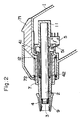
- Fig. 2 is an enlarged longitudinal sectional view of a portion of the radiant-energy clinical thermometer and illustrates the thermometer when not in use;
- Fig. 3 is an enlarged longitudinal sectional view of a portion of the radiant-energy clinical thermometer and illustrates the thermometer when in use;
- Fig. 4 is an enlarged transverse sectional view of a portion of the radiant-energy clinical thermometer and illustrates the thermometer when not in use;
- Fig. 5 is an enlarged transverse sectional view of a portion of the radiant-energy clinical thermometer and illustrates the thermometer when in use; and
- Fig. 6 is an enlarged transverse sectional view of a portion of the radiant-energy clinical thermometer and illustrates a cover of the thermometer in the detached state.
- Fig. 1 illustrates the overall configuration of a radiant-energy clinical thermometer.
- A case body 1 extends downwardly at an incline so as to be easily grasped by the hand. A body-temperature measuring circuit (not shown) is incorporated within the case body 1. A display unit, such as a liquid-
crystal display unit 15, for displaying a measured temperature is attached to one side of the case body 1 so that the temperature displayed on thedisplay unit 15 can be observed from the outside. - The upper portion of the case body 1 is integrally formed to include a supporting frame 11 to which a supporting
cylinder 2 is secured horizontally. A portion of the supportingcylinder 2 projects outwardly from the supporting frame 11. - A radiant-
temperature sensor 3 is secured to the distal end face of the supportingcylinder 2. The radiant-temperature sensor 3 is constituted by a thermopile, for example, and is connected to the body-temperature measuring circuit through lead wires disposed within the supportingcylinder 2. - A
cylindrical probe 4 is fitted over the supportingcylinder 2 and is free to slide in the longitudinal direction thereof. A switch, such as amicroswitch 5, is secured to the supporting frame 11. - The foregoing will be described in greater detail with reference to Figs. 2 and 3.
- The base portion of the
cylindrical probe 4 is formed to have a comparatively large inner diameter, and a gap is provided between inner peripheral surface of thecylindrical probe 4 and the outer peripheral surface of the supportingcylinder 2. Acoil spring 42 is disposed within the gap. One end of thecoil spring 42 abuts against the supporting frame 11, and the other end of the spring abuts against the inner wall surface of thecylindrical probe 4. Thecylindrical probe 4 is biased by thecoil spring 42 in a direction that thrusts the distal end of the probe outwardly. - The base end of the
cylindrical probe 4 is formed to have aflange 41. The supporting frame 11 is formed to have astopper 12 that engages with theflange 41. The extended position of thecylindrical probe 4 biased outwardly by thecoil spring 42 is decided by theflange 41 coming into contact with thestopper 12. When thecylindrical probe 4 is in the extended position, as shown in Fig. 2, its tip projects outwardly from the supportingcylinder 2 and thetemperature sensor 3 secured to the tip of the supportingcylinder 2 assumes a state in which the periphery thereof is completely covered by thecylindrical probe 4. The tip of thecylindrical probe 4 is open. - Part of the supporting frame 11 is cut away and a
lever 51 of themicroswitch 5 secured to the supporting frame 11 penetrates into the interior of the supporting frame 11 from the portion that has been cut away. When thecylindrical probe 4 is in the extended position, the base end of thecylindrical probe 4 is not in contact with thelever 51. Theswitch 5 is held in the off state at this time. - When the
cylindrical probe 4 is caused to retract against the biasing force of thespring 42 by an externally applied force, as shown in Fig. 3, thelever 51 of theswitch 5 is pushed by theflange 41 so that theswitch 5 is closed. An ON signal from theswitch 5 is applied to the temperature measuring circuit as the trigger signal for starting measurement. The retracted position of thecylindrical probe 4 is decided by theflange 41 coming into contact with a portion of the supporting frame 11. In this embodiment, the periphery of thetemperature sensor 3 is substantially protected by the tip portion of thecylindrical probe 4 even when thecylindrical probe 4 is in the retracted position. - The outer peripheral surface of the tip of
cylindrical probe 4 is formed so that the probe becomes incrementally more slender toward the tip. An annular groove is formed in the outer peripheral surface of the tip portion. - A
cover 9 is attached to the tip of thecylindrical probe 4 in a freely detachable manner. Thecover 9 is formed from a material that is as flexible as possible, and so as to free of corners, so that the orifice of an ear will not be hurt when the tip of thecylindrical probe 4 is inserted slightly into the ear orifice in order to measure body temperature. An annular projection formed on the inner peripheral surface of thecover 9 fits into the annular groove formed in the tip of thecylindrical probe 4. - The
cover 9 is prepared beforehand in a number of types having different sizes and shapes in conformity with sizes and shapes of ear orifices. Preferably, thecover 9 is changed for each individual whose body temperature is to be measured, and a cover suited to the individual is used. This is useful also in preventing the transmission of disease. - A
cover pushing member 7 is fitted onto the periphery of thecylindrical probe 4 so as to be free to move in the longitudinal direction thereof. Aslider 71 for being pushed by a finger is integrally formed on the pushingmember 7. Acoil spring 72 is provided between a portion of the case body 1 and a portion of the pushingmember 7 to bias the pushingmember 7 at its retracted position. The retracted position of the pushingmember 7 is decided by a portion of the pushingmember 7 coming into contact with a portion of the case body 1. By pushing theslider 71 against the biasing force of thespring 72, the pushingmember 7 is moved along the outer periphery of thecylindrical probe 4 to remove thecover 9 that has been attached to tip of thecylindrical probe 4. - As shown in Figs. 4 through 6, a locking lever 6 is mounted at its midpoint to the case body 1 by means of a
shaft 63 so as to be free to rock back and forth. - As illustrated in Fig. 4, the locking lever 6 is biased by a spring (not shown) in such a manner that an operating
portion 61 thereof projects slightly from the case body 1 while an actingportion 62 of the lever penetrates into the interior of the supporting case 11. In this state the tip of the actingportion 62 of locking lever 6 is in abutting contact with theflange 41 of thecylindrical probe 4 so that thecylindrical probe 4 is locked in the extended position. In other words, even if the tip of thecylindrical probe 4 is pressed in an effort to cause its retraction, theflange 41 abuts against the actingportion 62 so that thecylindrical probe 4 will not move. - When the operating
portion 61 of the locking lever 6 is pressed into the case body 1 by a finger or the like, as shown in Fig. 5, the actingportion 62 is moved outward so that it is disengaged from theflange 41 of thecylindrical probe 4. In this state, thecylindrical probe 4 is capable of being retracted by an external force against the biasing force of thespring 42. - When the radiant-energy clinical thermometer having this construction is not being used, the
cylindrical probe 4 is outwardly extended by the biasing force of thespring 42, as illustrated in Figs. 2 and 4. The actingportion 62 of the locking lever 6 engages theflange 41 so that thecylindrical probe 4 is held in the extended position. As a result, thecylindrical probe 4 will not retract, and theswitch 5 will not close, when the thermometer is carried about or even if the thermometer is handled carelessly. Since thecylindrical probe 4 is in the extended position, thetemperature sensor 3 attached to the distal end face of the supportingcylinder 2 is protected by thecylindrical probe 4 so that there is almost no danger of contamination or of adverse thermal effects. Since theflange 41 of thecylindrical probe 4 is spaced away from thelever 51 of theswitch 5, theswitch 5 is held in the off state. - In order to measure body temperature, the operating
portion 61 of the locking lever 6 is pressed. Since the actingportion 62 moves in the outward direction, its locking action is eliminated so that thecylindrical probe 4 attains a state in which it is capable of being extended or retracted. With the operatingportion 61 of the locking lever 6 being held in the pressed state, the tip of thecylindrical probe 4 to which thecover 9 has been attached is inserted slightly into the orifice of an ear and is pressed gently toward the orifice, whereupon thecylindrical probe 4 is retracted against the biasing force of thespring 42, as illustrated in Fig. 3. As a result, thetemperature sensor 3 is situated in the proximity of the opening in the tip of thecylindrical probe 4, and a state is attained in which thermal radiation from the external ear is capable of being sensed. Further, since theflange 41 of the retractedcylindrical probe 4 presses thelever 51 of theswitch 5, theswitch 5 is closed. The trigger signal generated by theswitch 5 is applied to the body-temperature measuring circuit to start the operation for measuring body temperature. Thetemperature sensor 3 accurately senses the heat rays emitted from within the orifice of the ear, and the body temperature is decided by the body-temperature measuring circuit based upon the output of thetemperature sensor 3. The body temperature determined is displayed on thedisplay unit 15. - Thus, by causing the cylindrical probe to retract by pressing it against the body part whose body temperature is to be measured, the
switch 5 is closed to automatically start the measurement of body temperature. As a result, a situation in which the timing at which body temperature is measured differs from person to person and from one time to another is avoided, thus making it possible to measure body temperature under identical conditions at all times. - When measurement of body temperature is concluded, the
cylindrical probe 4 need only be separated from the orifice of the ear. Thecylindrical probe 4 is extended and returns to its original position owing to the force of thespring 42. When the operatingportion 61 of the lever 6 is released, the lever 6 also returns to its original position so that thecylindrical probe 4 is locked. - The
cover 9 attached to the tip of-thecylindrical probe 4 is capable of being freely attached and detached. Accordingly, the cover best suited to the person undergoing temperature measurement may be selected and attached to thecylindrical probe 4. In order to remove thecover 9 from thecylindrical probe 4, theslider 71 need only be pressed to push off thecover 9 by the pushingmember 7. When theoptimum cover 9 is attached to thecylindrical probe 4, thecylindrical probe 4 will not move, even if it is pushed, since the actingportion 62 of the locking lever 6 is in abutting contact with theflange 41, as mentioned above. Thus thecover 9 may be attached in a reliable manner and theswitch 5 will not be closed inadvertently at this time. - Though the
microswitch 5 is illustrated in the foregoing embodiment, it goes without saying that a switch such as a proximity switch or photoelectric switch can also be used. - The present invention relates to improvements in a radiant-energy clinical thermometer, which is a clinical thermometer of a new type. Clinical thermometers fall within the purview of the medical-instruments industry and are utilized in this field.
Claims (6)
- A radiant-energy clinical thermometer comprising:
a support member having a portion projecting outwardly from a case body;
a radiant-temperature sensor attached to a tip of the outwardly projecting portion of said support member;
a cylindrical probe held by said support member in a freely extendible and retractable manner and having an open tip;
a biasing mechanism for biasing said cylindrical probe outwardly and holding the tip of said cylindrical probe at a position at which it covers the periphery of said temperature sensor; and
switch means for sensing that said cylindrical probe has been retracted against a biasing force of said biasing mechanism and generating a trigger signal that starts measurement of body temperature. - A radiant-energy clinical thermometer according to claim 1, further comprising a locking mechanism for preventing said cylindrical probe from retracting from the position at which it covers the periphery of said temperature sensor.
- A radiant-energy clinical thermometer according to claim 2, wherein said locking mechanism includes a locking lever operated from outside the case body.
- A radiant-energy clinical thermometer according to claim 1, wherein a cover suited to the ear of a human being is capable of being attached to the tip of said cylindrical probe.
- A radiant-energy clinical thermometer according to claim 1, further comprising a mechanism for pushing out said cover along said cylindrical probe in order to detach the cover attached to the tip of said cylindrical probe in a freely detachable manner.
- A radiant-energy clinical thermometer according to claim 5, wherein said pushing mechanism includes a slider operated from outside the case body.
Applications Claiming Priority (3)
| Application Number | Priority Date | Filing Date | Title |
|---|---|---|---|
| JP416036/90 | 1990-12-29 | ||
| JP2416036A JP3052379B2 (en) | 1990-12-29 | 1990-12-29 | Ear radiation thermometer |
| PCT/JP1991/001775 WO1992011800A1 (en) | 1990-12-29 | 1991-12-26 | Radiation sensing clinical thermometer |
Publications (3)
| Publication Number | Publication Date |
|---|---|
| EP0567646A1 true EP0567646A1 (en) | 1993-11-03 |
| EP0567646A4 EP0567646A4 (en) | 1994-04-13 |
| EP0567646B1 EP0567646B1 (en) | 1996-10-30 |
Family
ID=18524291
Family Applications (1)
| Application Number | Title | Priority Date | Filing Date |
|---|---|---|---|
| EP92901876A Expired - Lifetime EP0567646B1 (en) | 1990-12-29 | 1991-12-26 | Radiation sensing clinical thermometer |
Country Status (7)
| Country | Link |
|---|---|
| US (1) | US5340215A (en) |
| EP (1) | EP0567646B1 (en) |
| JP (1) | JP3052379B2 (en) |
| KR (1) | KR960015435B1 (en) |
| DE (1) | DE69122973T2 (en) |
| SG (1) | SG47705A1 (en) |
| WO (1) | WO1992011800A1 (en) |
Cited By (1)
| Publication number | Priority date | Publication date | Assignee | Title |
|---|---|---|---|---|
| ES2303451A1 (en) * | 2006-10-20 | 2008-08-01 | Xavier Botet Piro | Thermometer for skin and ear with retractable measurement end (Machine-translation by Google Translate, not legally binding) |
Families Citing this family (38)
| Publication number | Priority date | Publication date | Assignee | Title |
|---|---|---|---|---|
| US5487607A (en) * | 1992-04-08 | 1996-01-30 | Omron Corporation | Radiation clinical thermometer |
| JP3336359B2 (en) * | 1992-04-08 | 2002-10-21 | オムロン株式会社 | Radiation thermometer |
| JPH0856909A (en) * | 1994-08-23 | 1996-03-05 | Terumo Corp | Clinical thermometer |
| US5857775A (en) | 1995-09-05 | 1999-01-12 | Tyco Group S.A.R.L. | Thermometer probe having a watertight seal |
| DE19543096C2 (en) * | 1995-11-18 | 1998-07-23 | Braun Ag | Infrared radiation thermometer |
| US6030117A (en) | 1996-11-12 | 2000-02-29 | Trutek, Inc. | Tympanic thermometer probe cover |
| US5833367A (en) | 1996-11-12 | 1998-11-10 | Trutek, Inc. | Tympanic thermometer probe cover |
| US6001066A (en) | 1997-06-03 | 1999-12-14 | Trutek, Inc. | Tympanic thermometer with modular sensing probe |
| JPH1147098A (en) * | 1997-08-08 | 1999-02-23 | Omron Corp | Radial thermometer |
| US6058356A (en) * | 1998-04-30 | 2000-05-02 | Cooper Instrument Corporation | Hand-held electronic instrument |
| US5967992A (en) | 1998-06-03 | 1999-10-19 | Trutex, Inc. | Radiometric temperature measurement based on empirical measurements and linear functions |
| IL126224A0 (en) * | 1998-09-15 | 1999-05-09 | Gerlitz Jonathan | Ear thermometer and detector therefor |
| DE19842403B4 (en) * | 1998-09-16 | 2004-05-06 | Braun Gmbh | Radiation sensor with several sensor elements |
| US6461037B1 (en) * | 1999-02-28 | 2002-10-08 | Alaris Medical Systems, Inc. | Thermometer probe for use with disposable probe cover |
| US6123454A (en) | 1999-06-11 | 2000-09-26 | Trutek, Inc. | Tympanic thermometer disposable probe cover with further stretching prevention structure |
| DE19954756A1 (en) * | 1999-11-17 | 2001-05-31 | Odim Gmbh | Device and method for examining biological tissue |
| US6319206B1 (en) | 1999-11-24 | 2001-11-20 | Exergen Corporation | Temporal thermometer disposable cap |
| JP3858568B2 (en) * | 2000-06-09 | 2006-12-13 | オムロンヘルスケア株式会社 | Radiation thermometer and method for measuring body temperature using a radiation thermometer |
| WO2001096825A1 (en) * | 2000-06-13 | 2001-12-20 | Omron Corporation | Pyrometer |
| US20040095985A1 (en) * | 2002-11-15 | 2004-05-20 | Ko Kun Yuan | Dual-use infrared thermometer |
| US20060120432A1 (en) * | 2003-01-06 | 2006-06-08 | Loren Lantz | Tympanic thermometer with ejection mechanism |
| US6786636B1 (en) * | 2003-07-15 | 2004-09-07 | Norm Pacific Automation Corp. | Mechanism for removing probe cover from a thermometer probe |
| US7938783B2 (en) * | 2003-08-19 | 2011-05-10 | Advanced Monitors Corporation | Medical body core thermometer |
| US20050226307A1 (en) * | 2004-04-07 | 2005-10-13 | Sherin Lussier | Infrared thermometer |
| US20050228307A1 (en) * | 2004-04-13 | 2005-10-13 | Steve Gibree | Removable medical device adapter |
| US7857507B2 (en) * | 2004-11-16 | 2010-12-28 | Welch Allyn, Inc. | Temperature patch and method of using the same |
| US7507025B2 (en) * | 2005-08-29 | 2009-03-24 | Wayne R Lumpkin | Infrared thermometer with an axially actuated temperature sensor |
| TW200800098A (en) * | 2006-06-16 | 2008-01-01 | Radiant Innovation Inc | Infrared clinical thermometer |
| US7824102B2 (en) * | 2006-12-09 | 2010-11-02 | Shenzhen Mindray Bio-Medical Electronics, Inc. | Thermometer quick linkage apparatus and method |
| WO2008105869A1 (en) * | 2007-02-26 | 2008-09-04 | Welch Allyn, Inc. | Multi-site infrared thermometer |
| WO2009154612A1 (en) * | 2008-06-17 | 2009-12-23 | Welch Allyn, Inc. | Temperature patch and method of using the same |
| US8562209B2 (en) * | 2009-06-30 | 2013-10-22 | Edan Instruments, Inc. | Method to control the work of electronic thermometer by using the position of probe and the apparatus composed of |
| JP2011062369A (en) * | 2009-09-17 | 2011-03-31 | Terumo Corp | Ear type clinical thermometer |
| JP2011062370A (en) * | 2009-09-17 | 2011-03-31 | Terumo Corp | Ear type clinical thermometer |
| TWI495859B (en) * | 2009-10-05 | 2015-08-11 | Kaz Europe Sa | Multi-site attachments for ear thermometers |
| US8657758B2 (en) | 2010-12-02 | 2014-02-25 | Welch Allyn, Inc. | Devices and methods for temperature determination |
| TWM453480U (en) * | 2012-10-11 | 2013-05-21 | Avita Corp | Body temperature measuring device |
| KR102188912B1 (en) * | 2018-11-26 | 2020-12-09 | 재단법인 오송첨단의료산업진흥재단 | Core body temperature thermometer having a protruded thermistor |
Citations (3)
| Publication number | Priority date | Publication date | Assignee | Title |
|---|---|---|---|---|
| US4743122A (en) * | 1984-12-24 | 1988-05-10 | Sanyo Electric Co., Ltd. | Infrared-ray temperature measuring apparatus |
| US4784149A (en) * | 1986-01-13 | 1988-11-15 | Optical Sensors, Inc. | Infrared thermometer with automatic calibration |
| US4863281A (en) * | 1988-11-01 | 1989-09-05 | Diatak, Inc. | Probe cover ejection apparatus for medical thermometer |
Family Cites Families (12)
| Publication number | Priority date | Publication date | Assignee | Title |
|---|---|---|---|---|
| JPS56128135A (en) * | 1980-03-14 | 1981-10-07 | Olympus Optical Co | Endoscope |
| US4790324A (en) * | 1984-10-23 | 1988-12-13 | Intelligent Medical Systems, Inc. | Method and apparatus for measuring internal body temperature utilizing infrared emissions |
| JPH0657453B2 (en) * | 1985-08-29 | 1994-08-03 | 東レ株式会社 | Cleaning liquid supply device for printing machine |
| JP2504010B2 (en) * | 1986-12-22 | 1996-06-05 | 日本電装株式会社 | Generator control device mounted on the vehicle |
| JPS63157628U (en) * | 1987-04-03 | 1988-10-17 | ||
| WO1989006348A1 (en) * | 1987-12-25 | 1989-07-13 | Nippon Steel Corporation | Optical thermometer |
| US5018872A (en) * | 1988-11-01 | 1991-05-28 | Diatek, Inc. | Probe assembly for infrared thermometer |
| US5163418A (en) * | 1989-09-19 | 1992-11-17 | Thermoscan Inc. | Speculum cover |
| US4993424A (en) * | 1989-12-04 | 1991-02-19 | Diatek, Incorporated | Infrared medical thermometer |
| US5159936A (en) * | 1990-08-17 | 1992-11-03 | Mark Yelderman | Noncontact infrared tympanic thermometer |
| US5088834A (en) * | 1990-08-24 | 1992-02-18 | Thermoscan Inc. | Unitary probe cover |
| JP3012316B2 (en) * | 1990-11-29 | 2000-02-21 | タスコジャパン株式会社 | Radiation thermometer |
-
1990
- 1990-12-29 JP JP2416036A patent/JP3052379B2/en not_active Expired - Fee Related
-
1991
- 1991-12-26 DE DE69122973T patent/DE69122973T2/en not_active Expired - Fee Related
- 1991-12-26 KR KR1019930701953A patent/KR960015435B1/en not_active IP Right Cessation
- 1991-12-26 US US08/078,320 patent/US5340215A/en not_active Expired - Fee Related
- 1991-12-26 SG SG1996003917A patent/SG47705A1/en unknown
- 1991-12-26 EP EP92901876A patent/EP0567646B1/en not_active Expired - Lifetime
- 1991-12-26 WO PCT/JP1991/001775 patent/WO1992011800A1/en active IP Right Grant
Patent Citations (3)
| Publication number | Priority date | Publication date | Assignee | Title |
|---|---|---|---|---|
| US4743122A (en) * | 1984-12-24 | 1988-05-10 | Sanyo Electric Co., Ltd. | Infrared-ray temperature measuring apparatus |
| US4784149A (en) * | 1986-01-13 | 1988-11-15 | Optical Sensors, Inc. | Infrared thermometer with automatic calibration |
| US4863281A (en) * | 1988-11-01 | 1989-09-05 | Diatak, Inc. | Probe cover ejection apparatus for medical thermometer |
Non-Patent Citations (1)
| Title |
|---|
| See also references of WO9211800A1 * |
Cited By (1)
| Publication number | Priority date | Publication date | Assignee | Title |
|---|---|---|---|---|
| ES2303451A1 (en) * | 2006-10-20 | 2008-08-01 | Xavier Botet Piro | Thermometer for skin and ear with retractable measurement end (Machine-translation by Google Translate, not legally binding) |
Also Published As
| Publication number | Publication date |
|---|---|
| EP0567646A4 (en) | 1994-04-13 |
| SG47705A1 (en) | 1998-04-17 |
| DE69122973D1 (en) | 1996-12-05 |
| US5340215A (en) | 1994-08-23 |
| EP0567646B1 (en) | 1996-10-30 |
| KR960015435B1 (en) | 1996-11-14 |
| KR930702919A (en) | 1993-11-29 |
| JPH04242631A (en) | 1992-08-31 |
| WO1992011800A1 (en) | 1992-07-23 |
| JP3052379B2 (en) | 2000-06-12 |
| DE69122973T2 (en) | 1997-06-12 |
Similar Documents
| Publication | Publication Date | Title |
|---|---|---|
| EP0567646B1 (en) | Radiation sensing clinical thermometer | |
| US4784149A (en) | Infrared thermometer with automatic calibration | |
| US5487607A (en) | Radiation clinical thermometer | |
| US6001066A (en) | Tympanic thermometer with modular sensing probe | |
| US5163418A (en) | Speculum cover | |
| EP2486379B1 (en) | Attachment mechanism for ear thermometers | |
| US4602642A (en) | Method and apparatus for measuring internal body temperature utilizing infrared emissions | |
| US5411032A (en) | Electronic thermometer probe cover | |
| US4790324A (en) | Method and apparatus for measuring internal body temperature utilizing infrared emissions | |
| US5066142A (en) | Protective apparatus for a biomedical probe | |
| US6000845A (en) | Temperature sensing and indicating device | |
| EP1262753B1 (en) | Infrared clinical thermometer | |
| US7338206B2 (en) | Dual-use thermometer | |
| JPH0528617B2 (en) | ||
| JP2000504947A (en) | Infrared thermometer | |
| CA2368955A1 (en) | Thermometer probe for use with disposable probe cover | |
| US20040047392A1 (en) | Apparatus for measuring ear and forehead temperature | |
| EP0572095B1 (en) | Temperature measurement apparatus | |
| US7290926B2 (en) | Thermometer with movable cover | |
| EP0565123B1 (en) | Radiation clinical thermometer | |
| US5638951A (en) | Probe cover mounting case | |
| US20060120432A1 (en) | Tympanic thermometer with ejection mechanism | |
| JP2513637Y2 (en) | Radiation thermometer | |
| AU2003303687B2 (en) | Tympanic thermometer with ejection mechanism | |
| JP3615372B2 (en) | Infrared thermometer |
Legal Events
| Date | Code | Title | Description |
|---|---|---|---|
| PUAI | Public reference made under article 153(3) epc to a published international application that has entered the european phase |
Free format text: ORIGINAL CODE: 0009012 |
|
| 17P | Request for examination filed |
Effective date: 19930702 |
|
| AK | Designated contracting states |
Kind code of ref document: A1 Designated state(s): DE ES FR GB IT SE |
|
| A4 | Supplementary search report drawn up and despatched |
Effective date: 19940222 |
|
| AK | Designated contracting states |
Kind code of ref document: A4 Designated state(s): DE ES FR GB IT SE |
|
| GRAG | Despatch of communication of intention to grant |
Free format text: ORIGINAL CODE: EPIDOS AGRA |
|
| GRAG | Despatch of communication of intention to grant |
Free format text: ORIGINAL CODE: EPIDOS AGRA |
|
| GRAG | Despatch of communication of intention to grant |
Free format text: ORIGINAL CODE: EPIDOS AGRA |
|
| 17Q | First examination report despatched |
Effective date: 19960117 |
|
| GRAH | Despatch of communication of intention to grant a patent |
Free format text: ORIGINAL CODE: EPIDOS IGRA |
|
| GRAH | Despatch of communication of intention to grant a patent |
Free format text: ORIGINAL CODE: EPIDOS IGRA |
|
| GRAA | (expected) grant |
Free format text: ORIGINAL CODE: 0009210 |
|
| AK | Designated contracting states |
Kind code of ref document: B1 Designated state(s): DE ES FR GB IT SE |
|
| PG25 | Lapsed in a contracting state [announced via postgrant information from national office to epo] |
Ref country code: ES Free format text: THE PATENT HAS BEEN ANNULLED BY A DECISION OF A NATIONAL AUTHORITY Effective date: 19961030 |
|
| ITF | It: translation for a ep patent filed |
Owner name: STUDIO TORTA SOCIETA' SEMPLICE |
|
| REF | Corresponds to: |
Ref document number: 69122973 Country of ref document: DE Date of ref document: 19961205 |
|
| ET | Fr: translation filed | ||
| PG25 | Lapsed in a contracting state [announced via postgrant information from national office to epo] |
Ref country code: SE Effective date: 19970130 |
|
| PLBE | No opposition filed within time limit |
Free format text: ORIGINAL CODE: 0009261 |
|
| STAA | Information on the status of an ep patent application or granted ep patent |
Free format text: STATUS: NO OPPOSITION FILED WITHIN TIME LIMIT |
|
| 26N | No opposition filed | ||
| PGFP | Annual fee paid to national office [announced via postgrant information from national office to epo] |
Ref country code: GB Payment date: 19991115 Year of fee payment: 9 |
|
| PGFP | Annual fee paid to national office [announced via postgrant information from national office to epo] |
Ref country code: FR Payment date: 19991215 Year of fee payment: 9 |
|
| PGFP | Annual fee paid to national office [announced via postgrant information from national office to epo] |
Ref country code: DE Payment date: 19991223 Year of fee payment: 9 |
|
| PG25 | Lapsed in a contracting state [announced via postgrant information from national office to epo] |
Ref country code: GB Free format text: LAPSE BECAUSE OF NON-PAYMENT OF DUE FEES Effective date: 20001226 |
|
| GBPC | Gb: european patent ceased through non-payment of renewal fee |
Effective date: 20001226 |
|
| PG25 | Lapsed in a contracting state [announced via postgrant information from national office to epo] |
Ref country code: FR Free format text: LAPSE BECAUSE OF NON-PAYMENT OF DUE FEES Effective date: 20010831 |
|
| REG | Reference to a national code |
Ref country code: FR Ref legal event code: ST |
|
| PG25 | Lapsed in a contracting state [announced via postgrant information from national office to epo] |
Ref country code: DE Free format text: LAPSE BECAUSE OF NON-PAYMENT OF DUE FEES Effective date: 20011002 |
|
| PG25 | Lapsed in a contracting state [announced via postgrant information from national office to epo] |
Ref country code: IT Free format text: LAPSE BECAUSE OF NON-PAYMENT OF DUE FEES;WARNING: LAPSES OF ITALIAN PATENTS WITH EFFECTIVE DATE BEFORE 2007 MAY HAVE OCCURRED AT ANY TIME BEFORE 2007. THE CORRECT EFFECTIVE DATE MAY BE DIFFERENT FROM THE ONE RECORDED. Effective date: 20051226 |