EP0564858A2 - Method for resolving clusters of moving segments - Google Patents
Method for resolving clusters of moving segments Download PDFInfo
- Publication number
- EP0564858A2 EP0564858A2 EP93104364A EP93104364A EP0564858A2 EP 0564858 A2 EP0564858 A2 EP 0564858A2 EP 93104364 A EP93104364 A EP 93104364A EP 93104364 A EP93104364 A EP 93104364A EP 0564858 A2 EP0564858 A2 EP 0564858A2
- Authority
- EP
- European Patent Office
- Prior art keywords
- clusters
- moving
- segments
- circumscribing
- edge
- Prior art date
- Legal status (The legal status is an assumption and is not a legal conclusion. Google has not performed a legal analysis and makes no representation as to the accuracy of the status listed.)
- Granted
Links
Images


Classifications
-
- G—PHYSICS
- G08—SIGNALLING
- G08G—TRAFFIC CONTROL SYSTEMS
- G08G1/00—Traffic control systems for road vehicles
- G08G1/01—Detecting movement of traffic to be counted or controlled
- G08G1/015—Detecting movement of traffic to be counted or controlled with provision for distinguishing between two or more types of vehicles, e.g. between motor-cars and cycles
-
- G—PHYSICS
- G06—COMPUTING; CALCULATING OR COUNTING
- G06T—IMAGE DATA PROCESSING OR GENERATION, IN GENERAL
- G06T7/00—Image analysis
- G06T7/20—Analysis of motion
- G06T7/254—Analysis of motion involving subtraction of images
-
- G—PHYSICS
- G06—COMPUTING; CALCULATING OR COUNTING
- G06V—IMAGE OR VIDEO RECOGNITION OR UNDERSTANDING
- G06V10/00—Arrangements for image or video recognition or understanding
- G06V10/20—Image preprocessing
- G06V10/255—Detecting or recognising potential candidate objects based on visual cues, e.g. shapes
-
- G—PHYSICS
- G06—COMPUTING; CALCULATING OR COUNTING
- G06V—IMAGE OR VIDEO RECOGNITION OR UNDERSTANDING
- G06V20/00—Scenes; Scene-specific elements
- G06V20/50—Context or environment of the image
- G06V20/52—Surveillance or monitoring of activities, e.g. for recognising suspicious objects
- G06V20/54—Surveillance or monitoring of activities, e.g. for recognising suspicious objects of traffic, e.g. cars on the road, trains or boats
-
- G—PHYSICS
- G08—SIGNALLING
- G08G—TRAFFIC CONTROL SYSTEMS
- G08G1/00—Traffic control systems for road vehicles
- G08G1/01—Detecting movement of traffic to be counted or controlled
- G08G1/04—Detecting movement of traffic to be counted or controlled using optical or ultrasonic detectors
-
- G—PHYSICS
- G06—COMPUTING; CALCULATING OR COUNTING
- G06V—IMAGE OR VIDEO RECOGNITION OR UNDERSTANDING
- G06V2201/00—Indexing scheme relating to image or video recognition or understanding
- G06V2201/08—Detecting or categorising vehicles
Definitions
- the invention is therefore based on the object of specifying a method for generating a symbolic scene description of road traffic scenes for the purposes of traffic monitoring from video image sequences, which is based on inexpensive, generally available hardware, such as, for. B. a personal computer is applicable. Since the most important technical problem for the provision of such a method is the improvement of the resolution of vehicle clusters from a plurality of vehicles, which partially hide one another, and the separation of these clusters into individual vehicles, the invention is further based on the special task of an improved method for carrying out a resolution of such clusters.
- the method according to the invention is not only applicable for the analysis of road traffic scenes, but for the analysis of a large number of video sequences in which different objects move independently of one another and partially obscure one another.
- clusters of moving segments are detected in a first step by placing rectangles circumscribing the moving segments of a video image, the size of which is compared with a predetermined upper limit. Those moving segments whose circumscribing rectangles are larger than the specified upper limit are identified as clusters of moving segments.
- the second step is in each of these clusters Searched for a leading horizontal edge that has not yet been assigned a circumscribing rectangle. If such an edge is found, a circumscribing rectangle is assigned to it, which has the width of this edge and whose height is given by the average height of all objects of that object class from a predetermined set of object classes whose objects have an average width that is the width closest to the edge.
- moving segments and clusters of moving segments are detected in the images of a video image sequence.
- Such clusters of moving segments are broken down into segments with circumscribing rectangles, as a result of which moving objects, which partially obscure one another, are separated from one another.
- moving objects are tracked in their movement through the image plane and classified according to object classes.
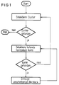
- FIG. 1 shows a schematic flow diagram of the method according to the invention for the resolution of clusters of moving segments.
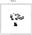
- FIG. 2 shows the moving segments and clusters of such moving segments in a video image of a video image sequence of a road traffic scene.
- Figure 3 shows circumscribing rectangles around moving segments and clusters of moving segments.
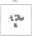
- FIG. 4 shows a resolution of clusters of moving segments with circumscribing rectangles of moving segments.
- FIG. 5 shows the use of the method according to the invention for resolving clusters of moving segments in the Generation of a symbolic scene description of a video image sequence.
- a conductive edge is understood to mean the first visible horizontal edge of a vehicle. It is mostly the shadow of the vehicle on the road. In the case of diffuse light, this edge part can be detected using suitable image evaluation methods. Under these conditions, a circumscribing rectangle is appropriate for the geometric description of a vehicle for the purposes of the evaluation methods envisaged here and meets the requirements for the classification of the vehicles.
- the object segment mask is segmented, ie contiguous pixel areas are combined to form a segment.
- B. using the method of C.-E. Liedtke and M. Ender. Knowledge-based image processing, pp. 62-67, Springer Verlag 1989, can be carried out.
- the circumscribing rectangle is used here to describe the moving objects.
- the width of the circumscribing rectangle in image coordinates is also converted into the real width of the vehicle using the inverse perspective transformation (KS Fu, RC Gonzales, CSG Lee: Robotics, pp. 307-325, Mc Graw-Hill Book Company 1987). If this width is greater than the maximum permitted width of an individual vehicle (usually 2.5 m), the moving object is identified as a vehicle cluster, ie there are several vehicles in a circumscribing rectangle (see FIG. 3).
- edges are obtained within the vehicle cluster.
- the circumscribing rectangle is placed over the edge closest to the camera. This edge is generally fully visible since it belongs to the first or last vehicle in a column.
- the width of this edge is used to calculate the width of the vehicle.
- the width of the edge is used to determine the class of the vehicle. Based on this class, the average height of the vehicles in this class can now be used.
- the next leading edge is now detected, which is located immediately to the left or right of the first edge (within this segment). It is assumed that depending on the location (right or left) the corresponding part of the edge is covered.
- the circumscribing rectangle with a medium width and height of a car is placed on the visible part. This step is repeated until no more conductive edges can be detected in the segment.
- the method is applied over the entire image sequence and the plausibility about the correct separation of vehicle clusters or the classification is recorded via the image sequence.
- FIG. 3 shows the vehicle clusters and their circumscribing rectangles in the image plane.
- the vehicle cluster labeled C consists of two individual vehicles.
- FIG. 4 shows how this vehicle cluster C is divided into two individual moving segments with their circumscribing ones using the method according to the invention Rectangles are broken down, each corresponding to a single vehicle.
- knowledge from previous images is also used to resolve the clusters into individual segments.
- Vehicles or moving objects in general that move away from the camera have normally been visible as isolated objects in previous times and have only formed clusters with other moving segments over time. This considerably simplifies the separation of such clusters that develop over time if appropriate lists of objects and moving segments are kept.
- moving objects that are moving towards the camera are first seen within clusters that gradually dissolve.
- a resolution algorithm based primarily on processing an image is advantageous.
- it is possible to establish plausibility values for the result of the cluster resolution by comparing images at different times. In doing so, segments that belong to the same moving object must also be combined. The same information is required for this as for resolving clusters.
- the results of this processing are stored in suitably structured object lists.
- classifying the objects When classifying the objects, they are assigned to one of several classes. In the case of motor vehicles, these classes are, for example: trucks, passenger cars, motorcycles and bicycles. It depends on the respective application situation which features of the objects are best suited for classification.
- trucks When an object moves towards the camera, it makes sense to use the width of the circumscribing rectangle as the first characteristic. This width is tracked over the entire sequence of images and is estimated over several images in the sequence.
- the conductive edge is used as a suitable feature. This leading edge is then in turn tracked over several images, an estimated value being calculated in each case. The predicted position is used to track characteristics. Another possible characteristic is the height of the circumscribing rectangle. All these measured values are filtered using Kalman filters or using a Kalman filter and the lengths and heights of the moving objects are calculated.
- the method according to the invention was tested with the aid of different traffic scenes under different lighting conditions. It shows that the errors in the estimation of positions and speeds were less than 3%.
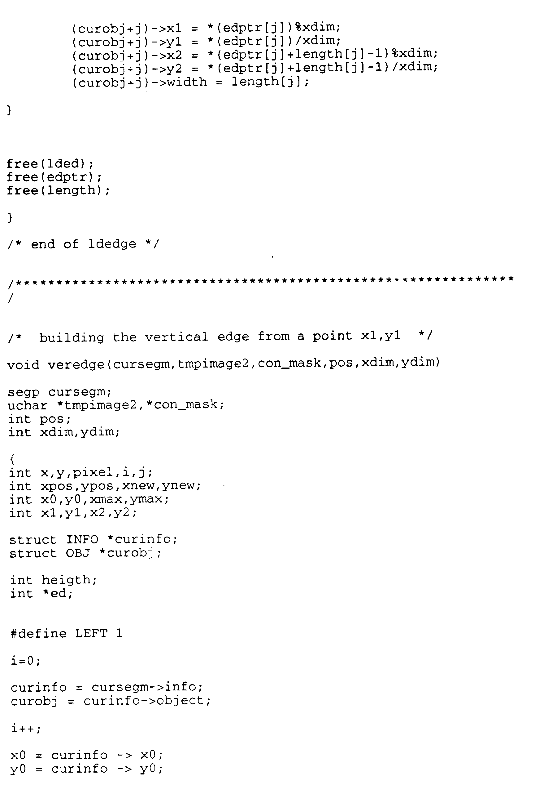
- the method according to the invention can be carried out, for example, with the aid of a computer program of the type below.
Abstract
Description
Zur Bewältigung heutiger Straßenverkehrsprobleme sind effiziente und intelligente Verfahren zur Verkehrssteuerung erforderlich. Eine wichtige Voraussetzung hierfür ist die Bereitstellung von Daten über den zu regelnden Straßenverkehr. Dies geschieht vorteilhafter Weise mit Hilfe von Videokameras, welche digitale Videobildsequenzen aufnehmen, aus denen die benötigten Verkehrsdaten ermittelt werden. Hierzu gehören beispielsweise die Zahl der vorhandenen Kraftfahrzeuge, der Kraftfahrzeugtyp, die Geschwindigkeit und Position eines jeden Fahrzeugs und die Bewegungsabläufe der Fahrzeuge. Verschiedene Autoren haben Verfahren zur Lösung der oben genannten Probleme vorgeschlagen (-A. Bielik, T. Abramczuk. Real-time wide-area traffic monitoring: information reduction and model-based approach. Proc. 6th Scandinavian Conference on Image Analysis, 1989, Oulu, Finland, pp.1223-1230; -S. Beucher, J.M. Blosseville, F. Lenoir. Traffic Spatial Measurements Using Video Image Processing. SPIE Vol.848 Intelligent Robots and Computer Vision: Sixth in a Series (1987), pp. 648-655; -N. Hoose, L.G. Willumsen. Automatically extracting traffic data from videotape using the CLIP4 parallel image processor. Patt. Recog. Letters, 6, 1987, pp. 199-213; A.D. Houghton, G.S. Hobson, N.L. Seed, R.C. Tocer. Automatic vehicle recognition, 1989, University of Sheffield, U.K.; -W. Leutzbach, H.P. Bähr, U. Becker, T. Vgtle. Entwicklung eines Systems zur Erfassung von Verkehrsdaten mittels photogrammetrischer Aufnahmeverfahren und Verfahren zur automatischen Bildauswertung. 1987, Technischer Schlußbericht, Universität Karlsruhe). Diese Verfahren sind jedoch nicht geeignet, die oben genannten Erfordernisse voll zu erfüllen. Insbesondere ist zur Durchführung dieser Verfahren eine teuere Spezialhardware erforderlich.Efficient and intelligent traffic control techniques are required to address today's road traffic problems. An important prerequisite for this is the provision of data about the road traffic to be regulated. This is advantageously done with the help of video cameras which record digital video image sequences from which the required traffic data are determined. These include, for example, the number of existing motor vehicles, the type of motor vehicle, the speed and position of each vehicle and the movement sequences of the vehicles. Various authors have proposed methods to solve the above problems (-A. Bielik, T. Abramczuk. Real-time wide-area traffic monitoring: information reduction and model-based approach. Proc. 6th Scandinavian Conference on Image Analysis, 1989, Oulu , Finland, pp. 1223-1230; -S. Beucher, JM Blosseville, F. Lenoir. Traffic Spatial Measurements Using Video Image Processing. SPIE Vol. 848 Intelligent Robots and Computer Vision: Sixth in a Series (1987), pp. 648 -655; -N. Hoose, LG Willumsen. Automatically extracting traffic data from videotape using the CLIP4 parallel image processor. Patt. Recog. Letters, 6, 1987, pp. 199-213; AD Houghton, GS Hobson, NL Seed, RC Tocer.Automatic vehicle recognition, 1989, University of Sheffield, UK; -W. Leutzbach, HP Bähr, U. Becker, T. Vgtle.Development of a system for recording traffic data using photogrammetric recording methods and methods for automatic image evaluation. 1987, final technical report , University t Karlsruhe). However, these methods are not suitable to fully meet the above requirements. In particular, this method is more expensive to carry out Special hardware required.
Der Erfindung liegt daher die Aufgabe zugrunde, ein Verfahren zur Erzeugung einer symbolischen Szenenbeschreibung von Straßenverkehrsszenen für Zwecke der Verkehrsüberwachung aus Videobildsequenzen anzugeben, welches auf einer kostengünstigen, allgemein verfügbaren Hardware, wie z. B. einem Personal Computer, anwendbar ist. Da das wichtigste technische Problem für die Bereitstellung eines solchen Verfahrens die Verbesserung der Auflösung von Fahrzeugclustern aus mehreren sich teilweise gegenseitig verdeckenden Fahrzeugen und die Trennung dieser Cluster in einzelne Fahrzeuge ist, liegt der Erfindung weiterhin die spezielle Aufgabe zugrunde, ein verbessertes Verfahren zur Durchführung einer Auflösung von solchen Clustern anzugeben.The invention is therefore based on the object of specifying a method for generating a symbolic scene description of road traffic scenes for the purposes of traffic monitoring from video image sequences, which is based on inexpensive, generally available hardware, such as, for. B. a personal computer is applicable. Since the most important technical problem for the provision of such a method is the improvement of the resolution of vehicle clusters from a plurality of vehicles, which partially hide one another, and the separation of these clusters into individual vehicles, the invention is further based on the special task of an improved method for carrying out a resolution of such clusters.
Diese Aufgaben werden durch ein Verfahren zur Auflösung von Clustern bewegter Segmente mit Merkmalen mit Anspruch 1 bzw. durch die Verwendung eines derartigen Verfahrens zur Erzeugung einer symbolischen Szenenbeschreibung einer Videobildsequenz mit Merkmalen nach Anspruch 4 gelöst.These tasks are solved by a method for resolving clusters of moving segments with features with
Das erfindungsgemäße Verfahren ist dabei nicht allein zur Analyse von Straßenverkehrsszenen anwendbar, sondern zur Analyse einer großen Zahl von Videosequenzen, in denen sich verschiedene Objekte unabhängig voneinander bewegen und sich dabei gegenseitig teilweise verdecken.The method according to the invention is not only applicable for the analysis of road traffic scenes, but for the analysis of a large number of video sequences in which different objects move independently of one another and partially obscure one another.
Bei dem erfindungsgemäßen Verfahren werden in einem ersten Schritt Cluster bewegter Segmente detektiert, indem um die bewegten Segmente eines Videobildes umschreibende Rechtecke gelegt werden, deren Größe mit einer vorgegebenen Obergrenze verglichen wird. Diejenigen bewegten Segmente, deren umschreibende Rechtecke größer sind als die vorgegebene Obergrenze werden als Cluster bewegter Segmente kenntlich gemacht. In einem zweiten Schritt wird in jedem dieser Cluster eine leitende horizontale Kante gesucht, der noch kein umschreibendes Rechteck zugeordnet ist. Wird eine solche Kante gefunden, wird ihr ein umschreibendes Rechteck zugeordnet, welches die Breite dieser Kante besitzt, und dessen Höhe durch die mittlere Höhe aller Objekte derjenigen Objektklasse aus einer vorgegebenen Menge von Objektklassen gegeben ist, deren Objekte eine mittlere Breite besitzen, die der Breite der Kante am nächsten liegt.In the method according to the invention, clusters of moving segments are detected in a first step by placing rectangles circumscribing the moving segments of a video image, the size of which is compared with a predetermined upper limit. Those moving segments whose circumscribing rectangles are larger than the specified upper limit are identified as clusters of moving segments. The second step is in each of these clusters Searched for a leading horizontal edge that has not yet been assigned a circumscribing rectangle. If such an edge is found, a circumscribing rectangle is assigned to it, which has the width of this edge and whose height is given by the average height of all objects of that object class from a predetermined set of object classes whose objects have an average width that is the width closest to the edge.
Bei einer Verwendung dieses Verfahrens zur Erzeugung einer symbolischen Szenenbeschreibung einer Videobildsequenz werden bewegte Segmente und Cluster aus bewegten Segmenten in den Bildern einer Videobildsequenz detektiert. Solche Cluster bewegter Segmente werden in Segmente mit umschreibenden Rechtecken aufgelöst, wodurch bewegte Objekte, die sich teilweise gegenseitig verdecken, voneinander getrennt werden. Diese bewegten Objekte werden in ihrer Bewegung durch die Bildebene verfolgt und nach Objektklassen klassifiziert.When using this method to generate a symbolic scene description of a video image sequence, moving segments and clusters of moving segments are detected in the images of a video image sequence. Such clusters of moving segments are broken down into segments with circumscribing rectangles, as a result of which moving objects, which partially obscure one another, are separated from one another. These moving objects are tracked in their movement through the image plane and classified according to object classes.
Figur 1 zeigt ein schematisches Ablaufdiagramm des erfindungsgemäßen Verfahrens zur Auflösung von Clustern bewegter Segmente.FIG. 1 shows a schematic flow diagram of the method according to the invention for the resolution of clusters of moving segments.
Figur 2 zeigt die bewegten Segmente und Cluster solcher bewegten Segmente in einem Videobild einer Videobildsequenz einer Straßenverkehrsszene.FIG. 2 shows the moving segments and clusters of such moving segments in a video image of a video image sequence of a road traffic scene.
Figur 3 zeigt umschreibende Rechtecke um bewegte Segmente und Cluster von bewegten Segmenten.Figure 3 shows circumscribing rectangles around moving segments and clusters of moving segments.
Figur 4 zeigt eine Auflösung von Clustern bewegter Segmente mit umschreibenden Rechtecken bewegter Segmente.FIG. 4 shows a resolution of clusters of moving segments with circumscribing rectangles of moving segments.
Figur 5 zeigt die Verwendung des erfindungsgemäßen Verfahrens zur Auflösung von Clustern bewegter Segmente bei der Erzeugung einer symbolischen Szenenbeschreibung einer Videobildsequenz.FIG. 5 shows the use of the method according to the invention for resolving clusters of moving segments in the Generation of a symbolic scene description of a video image sequence.
Im folgenden wird die Erfindung anhand eines bevorzugten Ausführungsbeispiels und mit Hilfe der Figuren näher beschrieben.The invention is described in more detail below with the aid of a preferred exemplary embodiment and with the aid of the figures.
Bei einer typischen Anordnung einer Videokamera zur Aufnahme von Videobildsequenzen von Straßenverkehrsszenen ist die Kamera seitlich der Straße in einer gewissen Höhe angebracht, z. B. auf einer Ampel oder einer Brücke. Daraus ergibt sich, daß die dicht hintereinander fahrenden Fahrzeuge in der Bildebene leicht gegeneinander versetzt erscheinen. Aus diesem Grunde ist immer ein Teil der vorderen leitenden Kante eines jeden Fahrzeugs zu sehen. Unter einer leitenden Kante sei in dieser Patentanmeldung die erste sichtbare horizontale Kante eines Fahrzeugs verstanden. Sie ist meistens der Schattenwurf des Fahrzeugs auf der Straße. Bei diffusem Licht kann dieser Kantenteil mittels geeigneter Bildauswerteverfahren detektiert werden. Unter diesen Voraussetzungen ist zur geometrischen Beschreibung eines Fahrzeugs für Zwecke der hier angedachten Auswerteverfahren ein umschreibendes Rechteck angemessen und genügt den Anforderungen zur Klassifikation der Fahrzeuge.In a typical arrangement of a video camera for recording video image sequences of road traffic scenes, the camera is attached to the side of the road at a certain height, e.g. B. on a traffic light or a bridge. It follows from this that the vehicles traveling closely behind one another appear slightly offset from one another in the image plane. For this reason, part of the leading edge of every vehicle is always visible. In this patent application, a conductive edge is understood to mean the first visible horizontal edge of a vehicle. It is mostly the shadow of the vehicle on the road. In the case of diffuse light, this edge part can be detected using suitable image evaluation methods. Under these conditions, a circumscribing rectangle is appropriate for the geometric description of a vehicle for the purposes of the evaluation methods envisaged here and meets the requirements for the classification of the vehicles.
Aus der Literatur sind verschiedene Verfahren zur Detektion bewegter Segmente in Videobildsequenzen bekannt (Feiten, W., Brandt, v. ,A., Lawitzky, G., Leuthäusser, I.: Ein videobasiertes System zur Erfassung von Verkehrsdaten. 13. DAGM-Symposium 1991, München; -K.P. Karmann, A.v. Brandt: Moving object segmentation based on adaptive reference images. proc. of EUSPICO 1990, 18.-21.09.90, Barcelona). Mit Hilfe dieser Verfahren werden Bewegtobjektsegmente sehr zuverlässig durch den Vergleich des laufenden Bildes mit einem Hintergrundbild detektiert. Der gesamte Detektionsalgorithmus für bewegte Segmente läuft dabei z. B. wie folgt ab:
- Subtraktion des laufenden Bildes von einem Hintergrundbild.
Es wird eine Schwellwertentscheidung durchgeführt, welche Regionen mit rascher Bewegung in der Bildebene von Regionen mit keiner oder langsamer Bewegung trennt. Hierdurch wird eine binäre Objektsegmentmaske erzeugt. Hierbei hängen die Eigenschaften dieser binären Objektsegmentmaske, bei der der unbewegte Hintergrund z. B. durch die Werte 0 und bewegte Segmente durch dieWerte 1 dargestellt werden, stark von dem gewählten Schwellwert ab. Wenn dieser Schwellwert zu hoch gewählt wird, wird die Objektsegmentmaske in der Regel stark fragmentiert sein (Figur 2). Im entgegengesetzten Fall, in dem der Schwellwert zu niedrig gewählt wird, werden große Mengen nicht interessierender Bewegungen detektiert, wie z. B. die Bewegung von Blättern. Dieses Problem wird aber mit Hilfe der erwähnten Verfahren durch eine adaptive Schwellwertwahl gelöst. - Segmentierung der Objektsegmentmaske.
Hierzu wird eine Segmentliste aufgebaut, in der für jedes zusammenhängende Gebiet ein umschreibendes Rechteck, dessen Fläche in der Bildebene und eine Schätzung für die entsprechende Fläche des wirklichen Objekts berechnet wird. Letztere wird unter Verwendung einer inversen perspektivischen Abbildung unter der Annahme, daß die Objekte sich auf einer Ebene bewegen, ermittelt. - Beseitigung von Segmenten, deren Zusammenhang mit Bewegtobjekten unwahrscheinlich ist.
Diese Segmente werden beseitigt, wenn sie außerhalb der Verkehrsbereiche liegen oder wenn sie zu klein sind, um echte interessierende Bewegtobjekte darzustellen. - Aktualisierung des Hintergrundbildes.
Außerhalb des Bereichs der Bewegtsegmente, d. h. dort, wo die Objektsegmentmaske den Wert 0 annimmt, wird eine Adaption zur Aktualisierung des Hintergrundbildes verwendet. Diese basiert auf einem rekursiven Filter mit variablen Koeffizienten. Die Maske besteht dabei aus den umschreibenden Rechtecken der einzelnen Fahrzeuge (Figur 4). Hierdurch werden die Objekte, die den Hintergrund verdecken, angemessener beschrieben, als durch die ursprüngliche Objektsegmentmaske, welche mit Hilfe des Schwellwerts erzeugt wurde.
- Subtraction of the current image from a background image.
A threshold decision is made which separates regions with rapid movement in the image plane from regions with no or slow movement. This creates a binary object segment mask. Here the properties of this binary object segment mask depend, in which the unmoving background z. B. represented by the values 0 and moving segments by thevalues 1, strongly depend on the selected threshold value. If this threshold value is chosen too high, the object segment mask will generally be highly fragmented (FIG. 2). In the opposite case, in which the threshold value is chosen too low, large amounts of movements of no interest are detected, such as e.g. B. the movement of leaves. However, this problem is solved with the help of the methods mentioned by an adaptive threshold value selection. - Segmentation of the object segment mask.
For this purpose, a segment list is built up in which a circumscribing rectangle is calculated for each connected area, its area in the image plane and an estimate for the corresponding area of the real object. The latter is determined using an inverse perspective image on the assumption that the objects move on a plane. - Eliminate segments that are unlikely to be associated with moving objects.
These segments are removed if they are outside the traffic areas or if they are too small to represent real objects of interest. - Update the background image.
Outside the area of the moving segments, ie where the object segment mask takes the value 0, an adaptation is used to update the background image. This is based on a recursive filter with variable coefficients. The mask consists of the circumscribing rectangles of the individual vehicles (Figure 4). In this way, the objects that cover the background are described more appropriately than by the original object segment mask, which was generated with the aid of the threshold value.
Auf der Grundlage derartiger Bewegtsegmente in Videobildern kommt nun das eigenliche erfindungsgemäße Verfahren zur Auflösung von Clustern bewegter Segmente zur Anwendung. Die Objektsegmentmaske wird segmentiert, d. h. es werden zusammenhängende Pixelbereiche zu einem Segment zusammengefaßt, was z. B. mit Hilfe des Verfahrens von C.-E. Liedtke und M. Ender. Wissensbasierte Bildverarbeitung, S. 62-67, Springer Verlag 1989, durchgeführt werden kann. Zur Beschreibung der Bewegtobjekte wird hier das umschreibende Rechteck genommen. Die Breite des umschreibenden Rechtecks in Bildkoordinaten wird ferner mittels der inversen perspektivischen Transformation (K.S. Fu, R.C. Gonzales, C.S.G. Lee: Robotics, pp. 307-325, Mc Graw-Hill Book Company 1987) in die reale Breite des Fahrzeugs umgerechnet. Ist diese Breite größer als die maximal zulässige Breite eines einzelnen Fahrzeugs (in der Regel 2,5 m), so wird das Bewegtobjekt als Fahrzeugcluster identifiziert, d. h. es befinden sich mehrere Fahrzeuge in einem umschreibenden Rechteck (s. Figur 3).On the basis of such moving segments in video images, the method according to the invention for the resolution of clusters of moving segments is now used. The object segment mask is segmented, ie contiguous pixel areas are combined to form a segment. B. using the method of C.-E. Liedtke and M. Ender. Knowledge-based image processing, pp. 62-67, Springer Verlag 1989, can be carried out. The circumscribing rectangle is used here to describe the moving objects. The width of the circumscribing rectangle in image coordinates is also converted into the real width of the vehicle using the inverse perspective transformation (KS Fu, RC Gonzales, CSG Lee: Robotics, pp. 307-325, Mc Graw-Hill Book Company 1987). If this width is greater than the maximum permitted width of an individual vehicle (usually 2.5 m), the moving object is identified as a vehicle cluster, ie there are several vehicles in a circumscribing rectangle (see FIG. 3).
Mit Hilfe eines geeigneten Bildauswerteverfahrens, z. B. mit Hilfe von Sobel-Operatoren (P. Haberäcker: Digitale Bildverarbeitung, Hanser Studien Bücher 1985) werden horizontale Kanten innerhalb des Fahrzeugclusters gewonnen. Über die zur Kamera am nächsten gelegene Kante wird das umschreibende Rechteck gelegt. Diese Kante ist im allgemeinen voll sichtbar, da sie zum ersten bzw. letzten Fahrzeug in einer Kolonne gehört. Zur Berechnung der Breite des Fahrzeugs wird die Breite dieser Kante genommen. Um zur Höhe des umschreibenden Rechtecks zu gelangen, wird anhand der Breite der Kante die Klasse des Fahrzeugs bestimmt. Anhand dieser Klasse kann nun die mittlere Höhe der Fahrzeuge dieser Klasse eingesetzt werden.With the help of a suitable image evaluation method, e.g. B. with the help of Sobel operators (P. Haberäcker: digital image processing, Hanser studies books 1985) horizontal edges are obtained within the vehicle cluster. The circumscribing rectangle is placed over the edge closest to the camera. This edge is generally fully visible since it belongs to the first or last vehicle in a column. The width of this edge is used to calculate the width of the vehicle. To get to the height of the circumscribing rectangle, the width of the edge is used to determine the class of the vehicle. Based on this class, the average height of the vehicles in this class can now be used.
Ausgehend von dem führenden Fahrzeug wird nun die nächste leitende Kante detektiert, die sich unmittelbar links oder rechts der ersten Kante befindet (innerhalb dieses Segmentes). Es wird dazu angenommen, daß je nach örtlicher Lage (rechts oder links) der entsprechende Teil der Kante verdeckt ist. Auf den sichtbaren Teil wird das umschreibende Rechteck mit mittlerer Breite und Höhe eines PKW gelegt. Dieser Schritt wird so lange wiederholt, bis keine leitenden Kanten mehr in dem Segment detektiert werden können.Starting from the leading vehicle, the next leading edge is now detected, which is located immediately to the left or right of the first edge (within this segment). It is assumed that depending on the location (right or left) the corresponding part of the edge is covered. The circumscribing rectangle with a medium width and height of a car is placed on the visible part. This step is repeated until no more conductive edges can be detected in the segment.
Das Verfahren wird über die ganze Bildsequenz angewendet und die Plausibilität über die korrekte Trennung von Fahrzeugclustern bzw. die Klassifizierung wird über die Bildsequenz festgehalten.The method is applied over the entire image sequence and the plausibility about the correct separation of vehicle clusters or the classification is recorded via the image sequence.
Figur 3 zeigt die Fahrzeugcluster und ihre umschreibenden Rechtecke in der Bildebene. Das mit C bezeichnete Fahrzeugcluster besteht, wie in Figur 3 sichtbar, aus zwei Einzelfahrzeugen. In Figur 4 ist dargestellt, wie dieses Fahrzeugcluster C mit Hilfe des erfindungsgemäßen Verfahrens in zwei einzelne Bewegtsegmente mit ihren umschreibenden Rechtecken zerlegt ist, die jeweils einem Einzelfahrzeug entsprechen.Figure 3 shows the vehicle clusters and their circumscribing rectangles in the image plane. As shown in FIG. 3, the vehicle cluster labeled C consists of two individual vehicles. FIG. 4 shows how this vehicle cluster C is divided into two individual moving segments with their circumscribing ones using the method according to the invention Rectangles are broken down, each corresponding to a single vehicle.
Bei einer bevorzugten Ausführungsform der Erfindung wird zur Auflösung der Cluster in einzelne Segmente auch von Wissen aus vorhergehenden Bildern Gebrauch gemacht. Fahrzeuge oder allgemein Bewegtobjekte, die sich von der Kamera entfernen, sind normaler Weise zu vorangehenden Zeiten als isolierte Objekte sichtbar gewesen und haben erst im Laufe der Zeit mit anderen Bewegtsegmenten Cluster gebildet. Hierdurch wird die Trennung solcher im Laufe der Zeit entstehenden Cluster erheblich vereinfacht, falls entsprechende Listen von Objekten und Bewegtsegmenten geführt werden. Andererseits werden Bewegtobjekte, die sich auf die Kamera zubewegen, zunächst innerhalb von Clustern gesehen, welche sich nach und nach auflösen. In diesem Fall ist ein Auflösungsalgorithmus vorteilhaft, der hauptsächlich auf der Verarbeitung eines Bildes basiert. In jedem Falle ist es möglich, durch Vergleich von Bilder zu verschiedenen Zeiten Plausibilitätswerte für das Ergebnis der Clusterauflösung aufzustellen. Dabei müssen auch Segmente, die zum selben Bewegtobjekt gehören, vereinigt werden. Hierzu wird die gleiche Information wie zum Auflösen von Clustern benötigt. Die Ergebnisse dieser Verarbeitung werden in geeignet strukturierten Objektlisten abgelegt.In a preferred embodiment of the invention, knowledge from previous images is also used to resolve the clusters into individual segments. Vehicles or moving objects in general that move away from the camera have normally been visible as isolated objects in previous times and have only formed clusters with other moving segments over time. This considerably simplifies the separation of such clusters that develop over time if appropriate lists of objects and moving segments are kept. On the other hand, moving objects that are moving towards the camera are first seen within clusters that gradually dissolve. In this case, a resolution algorithm based primarily on processing an image is advantageous. In any case, it is possible to establish plausibility values for the result of the cluster resolution by comparing images at different times. In doing so, segments that belong to the same moving object must also be combined. The same information is required for this as for resolving clusters. The results of this processing are stored in suitably structured object lists.
Zur Verfolgung von bewegten Objekten wird ein Tracking-Algorithmus verwendet, dessen Hauptaufgabe darin besteht, die detektierten Bewegtobjekte zu verfolgen und ihre jeweiligen Lagen im nächsten Bild vorherzusagen. In einer Trackliste wird die gesamte symbolische Szenenbeschreibung gespeichert. Jeder Track hat dabei die folgenden Attribute:
- Die laufende Position,
- die vorhergesagte Position im nächsten Bild,
- die momentane Geschwindigkeit,
- die vorhergesagte Geschwindigkeit im nächsten Bild,
- die Breite,
- ein Wert für die Plausibilität.
- The current position,
- the predicted position in the next picture,
- the current speed,
- the predicted speed in the next picture,
- the width,
- a value for the plausibility.
Der Tracking Algorithmus besteht dabei aus den folgenden Unteralogrithmen:
- Zuweisung detektierte Bewegtobjekte zu bestehenden Tracks: Dabei wird die Position eines Objekts definiert als der Mittelpunkt der führenden Kante. Das Objekt, welches sich am nächsten an der vorhergesagten Position eines Tracks befindet, wird diesem Track zugeordnet.
- Erzeugung neuer Tracks: Ein neuer Track wird erzeugt, falls ein detektiertes Objekt keinem existierendem Track zugeordnet werden kann.
- Beseitigung von Tracks: Falls im laufenden Zyklus ein Objekt keinem bestehenden Track zugeordnet werden kann, wird dieser Track mit Hilfe einer Kalmanfilter Prädiktion extra poliert. Falls die extra polierte Position sich außerhalb der Szene befindet, wird der Track beseitigt. Anderenfalls wird die Plausibilität dieses Tracks herabgesetzt. Falls die Plausibilität kleiner ist als eine vorgegebene Schranke, wird der Track ebenfalls beseitigt.
- Vorhersage der Position und der Geschwindigkeit für den nächsten Zyklus: Die Position und Geschwindigkeit der Tracks wird in Weltkoordinaten gefiltert unter Verwendung eines Kalmanfilters. Die Verwendung von Kalmanfiltern sorgt für eine Glättung der Meßwerte und stellt eine Schätzung der Lagen und Geschwindigkeiten der Bewegtobjekte zur Verfügung. Experimente haben ergeben, daß ein konstanter Kalmanfilter Koeffizient (Kalman-Gain) ausreichend ist.
- Assignment of detected moving objects to existing tracks: The position of an object is defined as the center of the leading edge. The object that is closest to the predicted position of a track is assigned to this track.
- Creation of new tracks: A new track is created if a detected object cannot be assigned to an existing track.
- Eliminating tracks: If an object cannot be assigned to an existing track in the current cycle, this track is specially polished using a Kalman filter prediction. If the extra polished position is outside the scene, the track is removed. Otherwise the plausibility of this track will be reduced. If the plausibility is less than a given limit, the track is also eliminated.
- Predicting the position and speed for the next cycle: The position and speed of the tracks is filtered in world coordinates using a Kalman filter. The use of Kalman filters smoothes the measured values and provides an estimate of the positions and speeds of the moving objects. Experiments have shown that a constant Kalman filter coefficient (Kalman gain) is sufficient.
Bei der Klassifikation der Objekte werden dieser einer von mehreren Klassen zugeordnet. Im Falle von Kraftfahrzeugen sind diese Klassen beispielsweise: Lastwagen, Personenkraftwagen, Motorräder und Fahrräder. Es hängt von der jeweiligen Anwendungssituation ab, welche Merkmale der Objekte sich am Besten zur Klassifikation eignen. Wenn ein Objekt sich auf die Kamera zubewegt, bietet es sich an, als erstes Merkmal die Breite des umschreibenden Rechtecks zu verwenden. Diese Breite wird über die gesamte Bildfolge verfolgt und sie wird über mehrere Bilder der Folge geschätzt.When classifying the objects, they are assigned to one of several classes. In the case of motor vehicles, these classes are, for example: trucks, passenger cars, motorcycles and bicycles. It depends on the respective application situation which features of the objects are best suited for classification. When an object moves towards the camera, it makes sense to use the width of the circumscribing rectangle as the first characteristic. This width is tracked over the entire sequence of images and is estimated over several images in the sequence.
Falls eine Drehbewegung eines Fahrzeugs oder allgemein eines Bewegtobjekts durch den Verfolgungsalgorithmus detektiert wird, wird die leitende Kante als geeignetes Merkmal herangezogen. Diese leitende Kante wird dann wiederum verfolgt über mehrere Bilder, wobei jeweils ein Schätzwert berechnet wird. Dabei wird die vorhergesagte Position zur Verfolgung von Merkmalen herangezogen. Ein anderes mögliches Merkmal ist die Höhe des umschreibenden Rechtecks. Alle diese Meßwerte werden mit Hilfe von Kalmanfiltern oder mit Hilfe eines Kalmanfilters gefiltert und dabei werden die Längen und Höhen der Bewegtobjekte berechnet.If a rotational movement of a vehicle or a moving object in general is detected by the tracking algorithm, the conductive edge is used as a suitable feature. This leading edge is then in turn tracked over several images, an estimated value being calculated in each case. The predicted position is used to track characteristics. Another possible characteristic is the height of the circumscribing rectangle. All these measured values are filtered using Kalman filters or using a Kalman filter and the lengths and heights of the moving objects are calculated.
Bei experimentellen Untersuchungen des erfindungsgemäßen Verfahrens stellte sich heraus, daß eine Bildauflösung von 256 x 256 Pixeln, eine Grauwerttiefe von 8 bit und eine Bildrate von 8 1/3 Hz ausreichend waren. Es konnte gezeigt werden, daß ein handelsüblicher Personal Computer auf der Basis eines Intel 386er Prozessors, unter Verwendung eines digitalen Signalprozessors und einer frame grabber Karte zur Durchführung einer Objektverfolgung in Echtzeit auf der Basis des erfindungsgemäßen Verfahrens ausreichend war. Dabei wird die low-level Bildverarbeitung (Hintergrundextraktion und Segmentierung) mit Hilfe des digitalen Signalprozessors durchgeführt. Der Wirtsrechner bearbeitet dagegen die Segmentliste und führt die high-level Algorithmen aus. Zusätzlich überwacht er die Kommunikation zwischen den verschiedenen Subsystemen des Gesamtsystems.In experimental investigations of the method according to the invention it was found that an image resolution of 256 x 256 pixels, a gray value depth of 8 bits and an image rate of 8 1/3 Hz were sufficient. It could be shown that a commercially available personal computer based on an Intel 386 processor, using a digital signal processor and a frame grabber card was sufficient for real-time object tracking on the basis of the method according to the invention. The low-level image processing (background extraction and segmentation) with the help of digital Signal processor performed. The host computer, on the other hand, processes the segment list and executes the high-level algorithms. In addition, it monitors the communication between the various subsystems of the overall system.
Das erfindungsgemäße Verfahren wurde mit Hilfe verschiedener Verkehrsszenen unter verschiedenen Beleuchtungsbedingungen getestet. Dabei zeigt sich, daß die Fehler in der Schätzung von Lagen und Geschwindigkeiten kleiner als 3 % waren.The method according to the invention was tested with the aid of different traffic scenes under different lighting conditions. It shows that the errors in the estimation of positions and speeds were less than 3%.
Das erfindungsgemäße Verfahren kann beispielsweise mit Hilfe eines Computer Programms der nachstehenden Art ausgeführt werden.


Claims (5)
Applications Claiming Priority (2)
| Application Number | Priority Date | Filing Date | Title |
|---|---|---|---|
| DE4211512 | 1992-04-06 | ||
| DE4211512 | 1992-04-06 |
Publications (3)
| Publication Number | Publication Date |
|---|---|
| EP0564858A2 true EP0564858A2 (en) | 1993-10-13 |
| EP0564858A3 EP0564858A3 (en) | 1995-04-12 |
| EP0564858B1 EP0564858B1 (en) | 1999-10-27 |
Family
ID=6456206
Family Applications (1)
| Application Number | Title | Priority Date | Filing Date |
|---|---|---|---|
| EP93104364A Expired - Lifetime EP0564858B1 (en) | 1992-04-06 | 1993-03-17 | Method for resolving clusters of moving segments |
Country Status (5)
| Country | Link |
|---|---|
| EP (1) | EP0564858B1 (en) |
| AT (1) | ATE186142T1 (en) |
| DE (1) | DE59309841D1 (en) |
| ES (1) | ES2140421T3 (en) |
| GR (1) | GR3032362T3 (en) |
Cited By (15)
| Publication number | Priority date | Publication date | Assignee | Title |
|---|---|---|---|---|
| DE19516664C1 (en) * | 1995-05-05 | 1996-08-29 | Siemens Ag | Processor-supported detection of selective target object in image |
| EP1087351A1 (en) * | 1999-09-24 | 2001-03-28 | Ascom Systec AG | Monitoring situation classification process using an image sequence |
| WO2003019234A1 (en) * | 2001-08-22 | 2003-03-06 | Ibeo Automobile Sensor Gmbh | Method for detecting and tracking objects |
| EP1306690A2 (en) * | 2001-09-28 | 2003-05-02 | IBEO Automobile Sensor GmbH | Method for recognising and tracking objects |
| EP1116962A3 (en) * | 2000-01-14 | 2003-12-03 | LFK-Lenkflugkörpersysteme GmbH | Method for the autonomous detection of helicopters |
| EP1460598A1 (en) * | 2003-03-17 | 2004-09-22 | Adam Mazurek | Process and apparatus for analyzing and identifying moving objects |
| USRE44225E1 (en) | 1995-01-03 | 2013-05-21 | Prophet Productions, Llc | Abnormality detection and surveillance system |
| USRE44527E1 (en) | 1995-01-03 | 2013-10-08 | Prophet Productions, Llc | Abnormality detection and surveillance system |
| US8818042B2 (en) | 2004-04-15 | 2014-08-26 | Magna Electronics Inc. | Driver assistance system for vehicle |
| US8842176B2 (en) | 1996-05-22 | 2014-09-23 | Donnelly Corporation | Automatic vehicle exterior light control |
| US8917169B2 (en) | 1993-02-26 | 2014-12-23 | Magna Electronics Inc. | Vehicular vision system |
| US8993951B2 (en) | 1996-03-25 | 2015-03-31 | Magna Electronics Inc. | Driver assistance system for a vehicle |
| US9171217B2 (en) | 2002-05-03 | 2015-10-27 | Magna Electronics Inc. | Vision system for vehicle |
| US9436880B2 (en) | 1999-08-12 | 2016-09-06 | Magna Electronics Inc. | Vehicle vision system |
| US10071676B2 (en) | 2006-08-11 | 2018-09-11 | Magna Electronics Inc. | Vision system for vehicle |
-
1993
- 1993-03-17 ES ES93104364T patent/ES2140421T3/en not_active Expired - Lifetime
- 1993-03-17 EP EP93104364A patent/EP0564858B1/en not_active Expired - Lifetime
- 1993-03-17 DE DE59309841T patent/DE59309841D1/en not_active Expired - Fee Related
- 1993-03-17 AT AT93104364T patent/ATE186142T1/en not_active IP Right Cessation
-
2000
- 2000-01-14 GR GR20000400060T patent/GR3032362T3/en not_active IP Right Cessation
Non-Patent Citations (2)
| Title |
|---|
| 13. DAGM SYMPOSIUM "MUSTERERKENNUNG 1991", Oktober 1991, M}NCHEN Seiten 507 - 514 FEITEN ET AL 'Ein videobasiertes System zur Erfassung von Verkehrsdaten' * |
| PATTERN RECOGNITION LETTERS, Bd.6, Nr.3, August 1987, HOLLAND Seiten 199 - 213 HOOSE ET AL 'Automatically extracting traffic data from video-tape using the CLIP4 parallel image processor' * |
Cited By (44)
| Publication number | Priority date | Publication date | Assignee | Title |
|---|---|---|---|---|
| US8917169B2 (en) | 1993-02-26 | 2014-12-23 | Magna Electronics Inc. | Vehicular vision system |
| USRE44225E1 (en) | 1995-01-03 | 2013-05-21 | Prophet Productions, Llc | Abnormality detection and surveillance system |
| USRE44527E1 (en) | 1995-01-03 | 2013-10-08 | Prophet Productions, Llc | Abnormality detection and surveillance system |
| US5828779A (en) * | 1995-05-05 | 1998-10-27 | Siemens Aktiengesellschaft | Method for constructing a color table in a computer unit for the classification of picture elements in an image |
| DE19516664C1 (en) * | 1995-05-05 | 1996-08-29 | Siemens Ag | Processor-supported detection of selective target object in image |
| US8993951B2 (en) | 1996-03-25 | 2015-03-31 | Magna Electronics Inc. | Driver assistance system for a vehicle |
| US8842176B2 (en) | 1996-05-22 | 2014-09-23 | Donnelly Corporation | Automatic vehicle exterior light control |
| US9436880B2 (en) | 1999-08-12 | 2016-09-06 | Magna Electronics Inc. | Vehicle vision system |
| EP1087351A1 (en) * | 1999-09-24 | 2001-03-28 | Ascom Systec AG | Monitoring situation classification process using an image sequence |
| EP1116962A3 (en) * | 2000-01-14 | 2003-12-03 | LFK-Lenkflugkörpersysteme GmbH | Method for the autonomous detection of helicopters |
| US6818883B2 (en) | 2000-01-14 | 2004-11-16 | Lfk-Lenkflugkoerpersysteme Gmbh | Method for the independent detection of helicopter |
| WO2003019234A1 (en) * | 2001-08-22 | 2003-03-06 | Ibeo Automobile Sensor Gmbh | Method for detecting and tracking objects |
| EP1306690A2 (en) * | 2001-09-28 | 2003-05-02 | IBEO Automobile Sensor GmbH | Method for recognising and tracking objects |
| EP1306690A3 (en) * | 2001-09-28 | 2004-02-04 | IBEO Automobile Sensor GmbH | Method for recognising and tracking objects |
| US9834216B2 (en) | 2002-05-03 | 2017-12-05 | Magna Electronics Inc. | Vehicular control system using cameras and radar sensor |
| US11203340B2 (en) | 2002-05-03 | 2021-12-21 | Magna Electronics Inc. | Vehicular vision system using side-viewing camera |
| US9171217B2 (en) | 2002-05-03 | 2015-10-27 | Magna Electronics Inc. | Vision system for vehicle |
| US10683008B2 (en) | 2002-05-03 | 2020-06-16 | Magna Electronics Inc. | Vehicular driving assist system using forward-viewing camera |
| US10351135B2 (en) | 2002-05-03 | 2019-07-16 | Magna Electronics Inc. | Vehicular control system using cameras and radar sensor |
| US9555803B2 (en) | 2002-05-03 | 2017-01-31 | Magna Electronics Inc. | Driver assistance system for vehicle |
| US10118618B2 (en) | 2002-05-03 | 2018-11-06 | Magna Electronics Inc. | Vehicular control system using cameras and radar sensor |
| US9643605B2 (en) | 2002-05-03 | 2017-05-09 | Magna Electronics Inc. | Vision system for vehicle |
| EP1460598A1 (en) * | 2003-03-17 | 2004-09-22 | Adam Mazurek | Process and apparatus for analyzing and identifying moving objects |
| US8818042B2 (en) | 2004-04-15 | 2014-08-26 | Magna Electronics Inc. | Driver assistance system for vehicle |
| US9191634B2 (en) | 2004-04-15 | 2015-11-17 | Magna Electronics Inc. | Vision system for vehicle |
| US9948904B2 (en) | 2004-04-15 | 2018-04-17 | Magna Electronics Inc. | Vision system for vehicle |
| US10015452B1 (en) | 2004-04-15 | 2018-07-03 | Magna Electronics Inc. | Vehicular control system |
| US11847836B2 (en) | 2004-04-15 | 2023-12-19 | Magna Electronics Inc. | Vehicular control system with road curvature determination |
| US10110860B1 (en) | 2004-04-15 | 2018-10-23 | Magna Electronics Inc. | Vehicular control system |
| US9609289B2 (en) | 2004-04-15 | 2017-03-28 | Magna Electronics Inc. | Vision system for vehicle |
| US10187615B1 (en) | 2004-04-15 | 2019-01-22 | Magna Electronics Inc. | Vehicular control system |
| US10306190B1 (en) | 2004-04-15 | 2019-05-28 | Magna Electronics Inc. | Vehicular control system |
| US9428192B2 (en) | 2004-04-15 | 2016-08-30 | Magna Electronics Inc. | Vision system for vehicle |
| US10462426B2 (en) | 2004-04-15 | 2019-10-29 | Magna Electronics Inc. | Vehicular control system |
| US9736435B2 (en) | 2004-04-15 | 2017-08-15 | Magna Electronics Inc. | Vision system for vehicle |
| US10735695B2 (en) | 2004-04-15 | 2020-08-04 | Magna Electronics Inc. | Vehicular control system with traffic lane detection |
| US11503253B2 (en) | 2004-04-15 | 2022-11-15 | Magna Electronics Inc. | Vehicular control system with traffic lane detection |
| US9008369B2 (en) | 2004-04-15 | 2015-04-14 | Magna Electronics Inc. | Vision system for vehicle |
| US11148583B2 (en) | 2006-08-11 | 2021-10-19 | Magna Electronics Inc. | Vehicular forward viewing image capture system |
| US11396257B2 (en) | 2006-08-11 | 2022-07-26 | Magna Electronics Inc. | Vehicular forward viewing image capture system |
| US10787116B2 (en) | 2006-08-11 | 2020-09-29 | Magna Electronics Inc. | Adaptive forward lighting system for vehicle comprising a control that adjusts the headlamp beam in response to processing of image data captured by a camera |
| US11623559B2 (en) | 2006-08-11 | 2023-04-11 | Magna Electronics Inc. | Vehicular forward viewing image capture system |
| US10071676B2 (en) | 2006-08-11 | 2018-09-11 | Magna Electronics Inc. | Vision system for vehicle |
| US11951900B2 (en) | 2006-08-11 | 2024-04-09 | Magna Electronics Inc. | Vehicular forward viewing image capture system |
Also Published As
| Publication number | Publication date |
|---|---|
| GR3032362T3 (en) | 2000-04-27 |
| ATE186142T1 (en) | 1999-11-15 |
| EP0564858B1 (en) | 1999-10-27 |
| EP0564858A3 (en) | 1995-04-12 |
| DE59309841D1 (en) | 1999-12-02 |
| ES2140421T3 (en) | 2000-03-01 |
Similar Documents
| Publication | Publication Date | Title |
|---|---|---|
| EP0669034B1 (en) | Process for detecting and eliminating the shadow of moving objects in a sequence of digital images | |
| EP2467828B1 (en) | Method and system for automatic object detection and subsequent object tracking in accordance with the object shape | |
| EP0564858B1 (en) | Method for resolving clusters of moving segments | |
| EP0385384B1 (en) | Detection process of moving objects in a sequence of digital images | |
| DE102014210820A1 (en) | Method for detecting large and passenger vehicles from fixed cameras | |
| EP0815539B1 (en) | Method of detecting moving objects in chronologically successive images | |
| DE19955919C1 (en) | Object recognition method for pixel images provides reduced image from input image which is divided by filtering into at least 2 filtered images each used for providing set of classification images | |
| DE102014216794A1 (en) | Robust and compute-efficient video-based object tracking in controlled motion environments | |
| DE102013205952A1 (en) | Reconfigurable system for detection of a clear path | |
| DE102011055458A1 (en) | Adaptation technology for the detection of a free lane by means of reliable local model calibration | |
| DE102017120729A1 (en) | Free space detection in a driver assistance system of a motor vehicle with a neural network | |
| EP2034461A2 (en) | Method for detecting and/or tracking moved objects in a monitoring zone with stoppers, device and computer program | |
| EP0973121A2 (en) | Image processing methods and devices for recognising road traffic objects | |
| EP3642758B1 (en) | Method for evaluating an optical appearance in the surroundings of a vehicle, and vehicle | |
| DE102011055459A1 (en) | Adaptation technology for the detection of a free lane with additional classifiers | |
| DE102012000459A1 (en) | Method for detecting object e.g. vehicle in surrounding area, involves transforming segments with classification surfaces into two-dimensional representation of environment, and searching and classifying segments in representation | |
| DE102015208139A1 (en) | Vehicle occupant detection by means of the distance between passenger and driver characteristics | |
| DE102019214558A1 (en) | PROJECTION INFORMATION RECOGNITION DEVICE BASED ON AN ARTIFICIAL NEURAL NETWORK AND PROCESSES OF THE SAME | |
| EP2483834B1 (en) | Method and apparatus for the recognition of a false object detection in an image | |
| EP3948649A1 (en) | Masking of objects contained in an image | |
| DE102018208481A1 (en) | Estimate a course of a rail track | |
| EP0763800A2 (en) | Object recognition method in moving images | |
| DE102015112389A1 (en) | Method for detecting at least one object on a road in a surrounding area of a motor vehicle, camera system and motor vehicle | |
| DE102014007994A1 (en) | Method for detecting light signals from road users | |
| DE19717814B4 (en) | Method for segmenting characters and symbols on license plates and formatted data carriers and for segmentation of patterns in complex scenes |
Legal Events
| Date | Code | Title | Description |
|---|---|---|---|
| PUAI | Public reference made under article 153(3) epc to a published international application that has entered the european phase |
Free format text: ORIGINAL CODE: 0009012 |
|
| AK | Designated contracting states |
Kind code of ref document: A2 Designated state(s): AT BE CH DE ES FR GB GR IT LI LU NL SE |
|
| PUAL | Search report despatched |
Free format text: ORIGINAL CODE: 0009013 |
|
| AK | Designated contracting states |
Kind code of ref document: A3 Designated state(s): AT BE CH DE ES FR GB GR IT LI LU NL SE |
|
| 17P | Request for examination filed |
Effective date: 19951009 |
|
| GRAG | Despatch of communication of intention to grant |
Free format text: ORIGINAL CODE: EPIDOS AGRA |
|
| GRAG | Despatch of communication of intention to grant |
Free format text: ORIGINAL CODE: EPIDOS AGRA |
|
| GRAH | Despatch of communication of intention to grant a patent |
Free format text: ORIGINAL CODE: EPIDOS IGRA |
|
| 17Q | First examination report despatched |
Effective date: 19990401 |
|
| GRAH | Despatch of communication of intention to grant a patent |
Free format text: ORIGINAL CODE: EPIDOS IGRA |
|
| GRAA | (expected) grant |
Free format text: ORIGINAL CODE: 0009210 |
|
| AK | Designated contracting states |
Kind code of ref document: B1 Designated state(s): AT BE CH DE ES FR GB GR IT LI LU NL SE |
|
| REF | Corresponds to: |
Ref document number: 186142 Country of ref document: AT Date of ref document: 19991115 Kind code of ref document: T |
|
| REG | Reference to a national code |
Ref country code: CH Ref legal event code: NV Representative=s name: SIEMENS SCHWEIZ AG Ref country code: CH Ref legal event code: EP |
|
| REF | Corresponds to: |
Ref document number: 59309841 Country of ref document: DE Date of ref document: 19991202 |
|
| ET | Fr: translation filed | ||
| GBT | Gb: translation of ep patent filed (gb section 77(6)(a)/1977) |
Effective date: 19991222 |
|
| ITF | It: translation for a ep patent filed |
Owner name: STUDIO JAUMANN P. & C. S.N.C. |
|
| REG | Reference to a national code |
Ref country code: ES Ref legal event code: FG2A Ref document number: 2140421 Country of ref document: ES Kind code of ref document: T3 |
|
| PLBE | No opposition filed within time limit |
Free format text: ORIGINAL CODE: 0009261 |
|
| STAA | Information on the status of an ep patent application or granted ep patent |
Free format text: STATUS: NO OPPOSITION FILED WITHIN TIME LIMIT |
|
| 26N | No opposition filed | ||
| REG | Reference to a national code |
Ref country code: GB Ref legal event code: IF02 |
|
| PGFP | Annual fee paid to national office [announced via postgrant information from national office to epo] |
Ref country code: AT Payment date: 20070209 Year of fee payment: 15 |
|
| PGFP | Annual fee paid to national office [announced via postgrant information from national office to epo] |
Ref country code: NL Payment date: 20070305 Year of fee payment: 15 |
|
| PGFP | Annual fee paid to national office [announced via postgrant information from national office to epo] |
Ref country code: LU Payment date: 20070309 Year of fee payment: 15 |
|
| PGFP | Annual fee paid to national office [announced via postgrant information from national office to epo] |
Ref country code: SE Payment date: 20070313 Year of fee payment: 15 Ref country code: GB Payment date: 20070313 Year of fee payment: 15 |
|
| PGFP | Annual fee paid to national office [announced via postgrant information from national office to epo] |
Ref country code: BE Payment date: 20070321 Year of fee payment: 15 |
|
| PGFP | Annual fee paid to national office [announced via postgrant information from national office to epo] |
Ref country code: ES Payment date: 20070424 Year of fee payment: 15 |
|
| PGFP | Annual fee paid to national office [announced via postgrant information from national office to epo] |
Ref country code: DE Payment date: 20070521 Year of fee payment: 15 |
|
| PGFP | Annual fee paid to national office [announced via postgrant information from national office to epo] |
Ref country code: CH Payment date: 20070607 Year of fee payment: 15 |
|
| PGFP | Annual fee paid to national office [announced via postgrant information from national office to epo] |
Ref country code: IT Payment date: 20070524 Year of fee payment: 15 |
|
| PGFP | Annual fee paid to national office [announced via postgrant information from national office to epo] |
Ref country code: GR Payment date: 20070216 Year of fee payment: 15 |
|
| PGFP | Annual fee paid to national office [announced via postgrant information from national office to epo] |
Ref country code: FR Payment date: 20070320 Year of fee payment: 15 |
|
| BERE | Be: lapsed |
Owner name: SIEMENS A.G. Effective date: 20080331 |
|
| REG | Reference to a national code |
Ref country code: CH Ref legal event code: PL |
|
| EUG | Se: european patent has lapsed | ||
| GBPC | Gb: european patent ceased through non-payment of renewal fee |
Effective date: 20080317 |
|
| PG25 | Lapsed in a contracting state [announced via postgrant information from national office to epo] |
Ref country code: AT Free format text: LAPSE BECAUSE OF NON-PAYMENT OF DUE FEES Effective date: 20080317 Ref country code: NL Free format text: LAPSE BECAUSE OF NON-PAYMENT OF DUE FEES Effective date: 20081001 |
|
| NLV4 | Nl: lapsed or anulled due to non-payment of the annual fee |
Effective date: 20081001 |
|
| REG | Reference to a national code |
Ref country code: FR Ref legal event code: ST Effective date: 20081125 |
|
| PG25 | Lapsed in a contracting state [announced via postgrant information from national office to epo] |
Ref country code: SE Free format text: LAPSE BECAUSE OF NON-PAYMENT OF DUE FEES Effective date: 20080318 Ref country code: LI Free format text: LAPSE BECAUSE OF NON-PAYMENT OF DUE FEES Effective date: 20080331 Ref country code: DE Free format text: LAPSE BECAUSE OF NON-PAYMENT OF DUE FEES Effective date: 20081001 Ref country code: CH Free format text: LAPSE BECAUSE OF NON-PAYMENT OF DUE FEES Effective date: 20080331 |
|
| PG25 | Lapsed in a contracting state [announced via postgrant information from national office to epo] |
Ref country code: BE Free format text: LAPSE BECAUSE OF NON-PAYMENT OF DUE FEES Effective date: 20080331 |
|
| PG25 | Lapsed in a contracting state [announced via postgrant information from national office to epo] |
Ref country code: FR Free format text: LAPSE BECAUSE OF NON-PAYMENT OF DUE FEES Effective date: 20080331 |
|
| REG | Reference to a national code |
Ref country code: ES Ref legal event code: FD2A Effective date: 20080318 |
|
| PG25 | Lapsed in a contracting state [announced via postgrant information from national office to epo] |
Ref country code: GR Free format text: LAPSE BECAUSE OF NON-PAYMENT OF DUE FEES Effective date: 20081002 Ref country code: GB Free format text: LAPSE BECAUSE OF NON-PAYMENT OF DUE FEES Effective date: 20080317 |
|
| PG25 | Lapsed in a contracting state [announced via postgrant information from national office to epo] |
Ref country code: ES Free format text: LAPSE BECAUSE OF NON-PAYMENT OF DUE FEES Effective date: 20080318 |
|
| PG25 | Lapsed in a contracting state [announced via postgrant information from national office to epo] |
Ref country code: IT Free format text: LAPSE BECAUSE OF NON-PAYMENT OF DUE FEES Effective date: 20080317 |
|
| PG25 | Lapsed in a contracting state [announced via postgrant information from national office to epo] |
Ref country code: LU Free format text: LAPSE BECAUSE OF NON-PAYMENT OF DUE FEES Effective date: 20080317 |