EP0558852A2 - An apparatus for recording and reproducing a digital audio signal - Google Patents
An apparatus for recording and reproducing a digital audio signal Download PDFInfo
- Publication number
- EP0558852A2 EP0558852A2 EP92309539A EP92309539A EP0558852A2 EP 0558852 A2 EP0558852 A2 EP 0558852A2 EP 92309539 A EP92309539 A EP 92309539A EP 92309539 A EP92309539 A EP 92309539A EP 0558852 A2 EP0558852 A2 EP 0558852A2
- Authority
- EP
- European Patent Office
- Prior art keywords
- digital audio
- band
- recording
- data
- identification data
- Prior art date
- Legal status (The legal status is an assumption and is not a legal conclusion. Google has not performed a legal analysis and makes no representation as to the accuracy of the status listed.)
- Granted
Links
Images


Classifications
-
- G—PHYSICS
- G11—INFORMATION STORAGE
- G11B—INFORMATION STORAGE BASED ON RELATIVE MOVEMENT BETWEEN RECORD CARRIER AND TRANSDUCER
- G11B20/00—Signal processing not specific to the method of recording or reproducing; Circuits therefor
- G11B20/10—Digital recording or reproducing
- G11B20/12—Formatting, e.g. arrangement of data block or words on the record carriers
- G11B20/1217—Formatting, e.g. arrangement of data block or words on the record carriers on discs
- G11B20/1251—Formatting, e.g. arrangement of data block or words on the record carriers on discs for continuous data, e.g. digitised analog information signals, pulse code modulated [PCM] data
-
- G—PHYSICS
- G11—INFORMATION STORAGE
- G11B—INFORMATION STORAGE BASED ON RELATIVE MOVEMENT BETWEEN RECORD CARRIER AND TRANSDUCER
- G11B20/00—Signal processing not specific to the method of recording or reproducing; Circuits therefor
- G11B20/10—Digital recording or reproducing
- G11B20/10527—Audio or video recording; Data buffering arrangements
-
- G—PHYSICS
- G11—INFORMATION STORAGE
- G11B—INFORMATION STORAGE BASED ON RELATIVE MOVEMENT BETWEEN RECORD CARRIER AND TRANSDUCER
- G11B27/00—Editing; Indexing; Addressing; Timing or synchronising; Monitoring; Measuring tape travel
- G11B27/02—Editing, e.g. varying the order of information signals recorded on, or reproduced from, record carriers
- G11B27/031—Electronic editing of digitised analogue information signals, e.g. audio or video signals
- G11B27/034—Electronic editing of digitised analogue information signals, e.g. audio or video signals on discs
-
- G—PHYSICS
- G11—INFORMATION STORAGE
- G11B—INFORMATION STORAGE BASED ON RELATIVE MOVEMENT BETWEEN RECORD CARRIER AND TRANSDUCER
- G11B27/00—Editing; Indexing; Addressing; Timing or synchronising; Monitoring; Measuring tape travel
- G11B27/10—Indexing; Addressing; Timing or synchronising; Measuring tape travel
- G11B27/102—Programmed access in sequence to addressed parts of tracks of operating record carriers
- G11B27/105—Programmed access in sequence to addressed parts of tracks of operating record carriers of operating discs
-
- G—PHYSICS
- G11—INFORMATION STORAGE
- G11B—INFORMATION STORAGE BASED ON RELATIVE MOVEMENT BETWEEN RECORD CARRIER AND TRANSDUCER
- G11B27/00—Editing; Indexing; Addressing; Timing or synchronising; Monitoring; Measuring tape travel
- G11B27/10—Indexing; Addressing; Timing or synchronising; Measuring tape travel
- G11B27/19—Indexing; Addressing; Timing or synchronising; Measuring tape travel by using information detectable on the record carrier
- G11B27/28—Indexing; Addressing; Timing or synchronising; Measuring tape travel by using information detectable on the record carrier by using information signals recorded by the same method as the main recording
- G11B27/30—Indexing; Addressing; Timing or synchronising; Measuring tape travel by using information detectable on the record carrier by using information signals recorded by the same method as the main recording on the same track as the main recording
- G11B27/3027—Indexing; Addressing; Timing or synchronising; Measuring tape travel by using information detectable on the record carrier by using information signals recorded by the same method as the main recording on the same track as the main recording used signal is digitally coded
-
- G—PHYSICS
- G11—INFORMATION STORAGE
- G11B—INFORMATION STORAGE BASED ON RELATIVE MOVEMENT BETWEEN RECORD CARRIER AND TRANSDUCER
- G11B20/00—Signal processing not specific to the method of recording or reproducing; Circuits therefor
- G11B20/10—Digital recording or reproducing
- G11B20/10527—Audio or video recording; Data buffering arrangements
- G11B2020/10537—Audio or video recording
- G11B2020/10592—Audio or video recording specifically adapted for recording or reproducing multichannel signals
-
- G—PHYSICS
- G11—INFORMATION STORAGE
- G11B—INFORMATION STORAGE BASED ON RELATIVE MOVEMENT BETWEEN RECORD CARRIER AND TRANSDUCER
- G11B2220/00—Record carriers by type
- G11B2220/20—Disc-shaped record carriers
- G11B2220/25—Disc-shaped record carriers characterised in that the disc is based on a specific recording technology
- G11B2220/2537—Optical discs
- G11B2220/2545—CDs
Definitions
- the invention relates to an apparatus for recording and reproducing a digital audio signal and, more particularly, to a recording and reproducing apparatus for a digital audio disc such as a Compact Disc or the like.
- CD Compact Disc
- MD Mini Disc
- a standard is widely used, which has a performance that the frequency band ranges from 0 Hz to 20 kHz, the number of quantization bits is equal to 16 bits, and the audio channels are two channels.
- the human ear can perceive the sound within a range from 20 Hz to 20 kHz. Therefore, the conventional CD satisfying the above performances is regarded to be satisfactory as a recording medium for audio apparatuses.
- the human ear has the capability of perceiving sounds having frequencies of 20 kHz and higher than 20 kHz. Accordingly, it is becoming required that the audio reproducing capability of the CD allows the reproduction of sounds having the frequency of 20 kHz or higher.
- Super CD a new CD standard which satisfies performance such that the frequency response band lies within a range from 0 Hz to 40 kHz, the number of quantization bits is 20 bits, and the audio channels are four channels.
- a reproducing apparatus of the Super CD having above standards will have a complicated circuit construction as compared with that of the apparatus designed for the conventional standard (the frequency band lies within a range from 0 Hz to 20 kHz, the number of quantization bits is 16 bits, and the audio channels are two channels), so that such a reproducing apparatus will become expensive. If the above standard of the Super CD is adopted as a general standard, it will compel also users who do not require a high sound quality to purchase such an expensive reproducing apparatus with a high sound quality. This will makes an obstacle for the generalization of the Super CD standard.
- the present invention contemplates to eliminate such a problem and it is an object of the present invention to provide, as a recording and reproducing apparatus of a Super CD having a wider band, a higher sound quality, and more channels than conventional CD, a digital audio signal recording and reproducing apparatus in which adopted a recording method capable of operating for a reproducing apparatus whose price is reduced while satisfying the performance of conventional standard and also for a high sound quality reproducing apparatus of a high price satisfying the standard of the Super CD.
- a recording medium for digital audio signals according to the present invention is of a type in which the digital audio signals are recorded after divided into blocks, the recording medium having an information data section comprising a plurality of subblocks, and a header section arranged at the position preceding the information data section, and including a plurality of identification data blocks each indicating a frequency band at least corresponding to the respective subblocks.
- a recording apparatus for digital audio signals comprises converting means for converting input digital audio signals into groups of band digital data for each frequency band, subblock producing means for dividing each of the band digital data groups along a time base, thereby obtaining band subblocks, information data section producing means for combining the band subblocks in a same time zone among the band subblocks, thereby obtaining an information data section; header section producing means for producing a header section including identification data blocks indicative of the frequency band of each subblock included in the information data section; block producing means for combining the information data section and the header section, thereby producing a block; and recording means for recording the block on a recording medium.
- a digital audio signal reproducing apparatus is designed for reproducing information from a recording medium on which digital audio signals are recorded after divided into blocks each of which in constituted by an information data section consisting of a plurality of subblocks and a header section which is arranged at a position preceding the information data section and includes a plurality of identification data blocks indicative of at least the frequency band corresponding to the respective subblocks, wherein the reproducing apparatus comprises: reading means for reading the digital audio signal from the recording medium; and extracting means for obtaining identification data in the header section for each block from the digital audio signal which is generated by the reading means and for extracting the digital audio signals on a subblock unit basis in accordance with the identification data when the identification data is equal to a predetermined identification data, thereby obtaining a reproduction signal.
- a digital audio signal reproducing apparatus is designed for reproducing information from a recording medium on which digital audio signals are recorded after divided into blocks each of which in constituted by an information data section consisting of a plurality of subblocks and a header section which is arranged at the position preceding the information data section and includes a plurality of identification data blocks indicative of at least the frequency band corresponding to the respective subblocks
- the reproducing apparatus comprises: reading means for reading a digital signal from the recording medium; extracting means for obtaining identification data in the header section for each block from the digital signal which is generated by the reading means and for extracting the digital audio signals on a subblock unit basis in accordance with the identification data in the header section when the identification data is equal to predetermined identification data; and band synthesizing means for performing a band synthesizing operation to a selected ones of plurality of digital audio signals among the digital audio signals extracted by the extracting means, thereby obtaining reproduction signals.
- the recording apparatus of digital audio signals according to the invention is configured to produce data from recording audio signals for each of plurality of frequency components and records the respective data and, add the identification data indicative of the frequency band of each data and records the resultant data.
- the digital audio signal reproducing apparatus according to the invention selectively extracts the data by using the identification data and reproduces the selected data.
- the embodiment includes a recording medium for recording audio signals whose frequency band lies within a range from 0 Hz to 40 kHz, the number of quantization bits is 20 bits, and the audio channels are four channels.
- the embodiment also includes a recording apparatus and a reproducing apparatus for such a recording medium.
- Fig. 1 shows a data format of one block recorded on the recording medium according to the invention.
- One block comprises an address section, a header section, and an information data section.
- An address indicative of the position of the block is recorded in the address section arranged at a leading position of the block.
- the information data section in constituted by nine subblocks and the data which has been frequency-band divided for each audio signal channel is stored in each of the subblocks.
- the header section comprises nine subblock headers. Labels have been recorded in the header section as identification data indicative of the kinds of audio signals channels and frequency bands of the above nine subblocks. For instance, the kind of data recorded in the subblock 0 in Fig. 1 can be, accordingly, discriminated by the label of the identification data recorded in the subblock header 0. The kind of data recorded in the subblock 8 can be discriminated by the label of the identification data recorded in the subblock header 8.
- one block with such a construction repetitively exists along the track in accordance with the order of addresses.
- a sync signal (not shown in Fig. 1) is inserted between the continuous blocks.
- Fig. 2 is a diagram showing a construction of the recording apparatus of digital audio signals according to the invention.
- the recording audio signals of the channels 1 to 4 are supplied to band dividing and data producing circuit 1a to 1d.
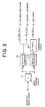
- Each of the band dividing and data producing circuit 1a to 1d has the same internal construction as shown in Fig. 3.
- band dividing circuit 11 performs band-division of the recording audio signals in the form of analog signals into the audio signal component of 0 Hz to 20 kHz and the audio signal component of 20 kHz to 40 kHz and supplies them to 20-bit A/D converters 12 and 13, respectively.
- the 20-bit A/D converter 12 performs a 20-bit quantization for a audio signal component of 0 Hz to 20 kHz and generates the high-order 16 bits among the 20 bits as a low-band high-order signals and generates the low-order four bits as a low-band low-order signal.
- the 20-bit A/D converter 13 performs the 20-bit quantization for a recording audio signal component of 20 kHz to 40 kHz and supplies the 20-bit quantization signal to 20-16 bit compressing circuit 14.
- the 20-16 bit compressing circuit 14 compresses the 20-bit quantization signal into 16 bits by a method such as a differential PCM method or the like and generates as a high-band signal.
- the band dividing circuit 11 is, for instance, an analog band pass filter comprising a capacitor and a resistor element. It is, however, also possible to use a method of performing a band division by a digital signal processing circuit using a DCT (Discrete Cosine Transform). According to the above method, the analog recording audio signals are supplied to the band dividing circuit 11 using the DCT through A/D converters (not shown). In such a case, the 20-bit A/D converters 12 and 13 are unnecessary.
- DCT Discrete Cosine Transform
- the band dividing and data producing circuit 1a to 1d produce the low-band high-order signals and low-band low-order signals which have been quantized every channel of the recording audio signals and the high-band signals and supply to block forming circuit 2.
- the output signals of the band dividing and data producing circuit 1a to 1d will now be referred to as denominations shown in Fig. 4 hereinbelow.
- the low-band high-order signal, low-band low-order signal, and high-band signal which are generated from the band dividing and data producing circuit 1a are set to "A1L", "ALQ(1/4)", and "A1H", respectively.
- the low-band high-order signals, low-band low-order signal, and high-band signal which are generated from the band dividing and data producing circuit 1b are set to "A2L”, “ALQ(2/4)", and “A2H", respectively.
- the low-band high-order signal, low-band low-order signal, and high-band signal which are generated from the band dividing and data producing circuit 1c are set to "A3L”, “ALQ(3/4)", and "A3H", respectively.
- the low-band high-order signal, low-band low-order signal, and high-band signal which are generated from the band dividing and data producing circuit Id are set to "A4L", “A4L”, “ALQ(4/4), and "A4H", respectively.
- the block forming circuit 2 divides those signals on the time base.
- the signals existing in the same time zone are combined and are assigned to the subblocks 0 to 8 in the information data section in Fig. 1.
- the block forming circuit 2 forms labels as identification data to indicate the kinds of data recorded in the subblocks 0 to 8, that is, the kinds of audio signal channels and frequency bands and assigns to the subblock headers 0 to 8 in Fig. 1.
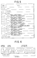
- Fig. 5 shows a correspondence table between the output signals of the band dividing and data producing circuit 1a to 1d which have been recorded in the subblocks 0 - to 8 and the labels.
- the label "10" corresponds to "A1L”
- the label "14" corresponds to "ALQ”.
- "ALQ" of the label "14” denotes the combination of "ALQ(1/4)", “ALQ(2/4)", “ALQ(3/4)", and "ALQ(4/4).
- the block forming circuit 2 forms one block by combining the information data section and the header section and forms a signal shown in Fig. 6 by further adding an address indicative of the position of the block to the head of the block and supplies the resultant signal to an encoding circuit 3.
- the encoding circuit 3 adds an error correction code to an output signal of the block forming circuit 2 and supplies a resultant signal to a modulating circuit 4.
- the modulating circuit 4 executes, for instance, an EFM (Eight to Fourteen Modulation) process.
- the modulated signal is supplied to an optical head 5 and is photoelectrically converted into the electric signal and recorded onto an optical disc 7 which is rotated by a spindle motor 6.
- the labels shown in Fig. 5 there are labels which are not disclosed in the above description and these labels are used to provide applications in an apparatus having another system construction which is not described in the embodiment.
- the label "00" is used when the data recorded there doesn't have any meaning.
- the label "00" is added to the unnecessary data.
- the system accordingly, doesn't need to read out the memory locations at which the unnecessary data has been recorded, so that a using efficiency can be raised.
- the label "01” denotes that a control program or the like which is used in the system has been recorded.
- the labels "02” to “0F” and the labels "19" to "FF” are provided as spare labels. When the kinds of data are expanded or the like, it is possible to cope with such an expansion by using the spare labels.
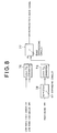
- a reproducing apparatus of digital audio signals in the invention shown in Fig. 7 reproduces a Super CD in which audio signals of the standards in which a frequency band lies within a range from 0 - Hz to 40 kHz and the number of quantization bits is set to 20 bits and the audio channels are set to four channels have been recorded.
- An optical pickup 71 reads information from the optical disc 7 and obtains a reproduction signal.
- the reproduction signal is EFM (Eight to Fourteen Modulation) demodulated by a demodulating circuit 72 and supplied to an error correcting circuit 73.
- the error correcting circuit 73 corrects errors in an output signal of the demodulating circuit 72 and supplies the error corrected signal to signal extracting circuit 74.
- the signal shown in Fig. 6 is derived as an output signal of the error correcting circuit 72.
- the signal extracting circuit 74 detects the labels which are equal to "10”, “11”, “12”, “13”, “14”, “15”, “16", “17”, and “18” from the subblock header areas of the signal every block and separates and extracts the data of the subblocks corresponding to those labels, namely, "A1L”, “A2L”, “A3L”, “A4L”, “A1H”, “A2H”, “A3H”, “A4H", and "ALQ".
- the signal extracting circuit 74 supplies "A1L” and “A1H” to a band synthesis and reproduction signal producing circuit 75a, "A2L” and “A2H” to band synthesis and reproduction signal producing circuit 75c, "A3L” and “A3H” to band synthesis and reproduction signal producing circuit 75c, and “A4L” and “A4H” to band synthesis and reproduction signal producing circuit 75d, respectively.
- the separated and extracted "ALQ” 16 bits are further separated into "ALQ(1/4)", “ALQ(2/4)", “ALQ(3/4)", and "ALQ(4/4)" each consisting of four bits.
- Each of the band synthesis and reproduction signal producing circuit 75a to 75d has the same internal construction as shown in Fig. 8.
- a 20-bit D/A converter 76 receives the 20-bit digital audio signals comprising a combination of the low-band high-order signals (corresponding to "A1L”, “A2L”, “A3L”, and “A4L”) as 16-bit digital audio signals and the low-band low-order signals (corresponding to "ALQ(1/4)", “ALQ(2/4)", “ALQ(3/4)", and “ALQ(4/4)") as 4-bit digital audio signals and converts into the analog signal and supplies it to a band synthesizing circuit 77.
- a 16-20 bit expanding circuit 78 receives the high-band signals (corresponding to "A1H”, “A2H”, “A3H”, and “A4H") as 16-bit digital audio signals compressed by the 20-16 bit compressing circuit 14 and expands to the 20-bit digital audio signals and supplies them to a 20-bit D/A converter 79.
- the 20-bit D/A converter 79 converts the supplied 20-bit digital audio signals into the analog signal and supplies it to the band synthesizing circuit 77.
- the band synthesizing circuit 77 band synthesizes the analog signal from the 20-bit D/A converter 76 and the analog signal from the 20-bit D/A converter 79 and generates the resultant synthesis signal as a reproduction audio signal.
- the band synthesis and reproduction signal producing circuit 75b band-synthesizes the signals “A2L”, “A2H”, and “ALQ(2/4)” and generates the resultant synthesis signal as a reproduction audio signal channel 2.
- the band synthesis and reproduction signal producing circuit 75c band-synthesizes the signals “A3L”, “A3H”, and “ALQ(3/4)” and generates the resultant synthesis signal as a reproduction audio signal channel 3.
- the band synthesis and reproduction signal producing circuit 75d band-synthesizes the signals "A4L”, “A4H”, and “ALQ(4/4)” and generates the resultant synthesis signal as a reproduction audio signal channel 4.
- the optical pickup 71 reads the information from the optical disc 7 and obtains the reproduction signal.
- the reproduction signal is EFM (Eight to Fourteen Modulation) demodulated by the demodulating circuit 72 and the demodulated signal is supplied to the error correcting circuit 73.
- the error correcting circuit 73 corrects errors in the output signal of the demodulating circuit 72 and supplies the error corrected signal to extracting circuit 91.
- an output signal of the error correcting circuit 73 is a signal shown in Fig. 6.
- the extracting circuit 91 detects the label "10" (label corresponding to "A1L”) and the label "11” (label corresponding to "A2L”) from the subblock header region of this signal and extracts the data "A1L” and "A2L” of the subblocks corresponding to those labels and supplies the extracted data to 16-bit D/A converters 92 and 93, respectively.
- the 16-bit D/A converter 92 converts "A1L” as a digital audio signal into the analog signal and generates as a reproduction audio signal channel 1.
- the 16-bit D/A converter 93 converts "A2L” as a digital audio signal into the analog signal and generates as a reproduction audio signal channel 2.
- the recording apparatus of the digital audio signal of the invention is configured to produce data of a plurality of frequency components from the audio signals to be recorded and to record the produced.
- the recording apparatus further, adds identification data indicative of the kind of each data and records the resultant data, respectively.
- the digital audio signal reproducing apparatus of the invention is configured to selectively extract each of the above data by the identification data and to reproduce the extracted data.
- the reproducing apparatus of the Super CD can be formed as an apparatus of a relatively high price which can reproduce a high quality sound.
- a relatively low price reproducing apparatus can be realized while the quality of the reproduced sound doesn't necessarily satisfy the capability of the Super CD.
- the performance of the reproduction apparatus can be selected arbitrarily.
Abstract
Description
- The invention relates to an apparatus for recording and reproducing a digital audio signal and, more particularly, to a recording and reproducing apparatus for a digital audio disc such as a Compact Disc or the like.
- In digital audio recording mediums such as Compact Disc (hereinafter, referred to as CD), Mini Disc (hereinafter, referred to as MD), or the like, a standard is widely used, which has a performance that the frequency band ranges from 0 Hz to 20 kHz, the number of quantization bits is equal to 16 bits, and the audio channels are two channels.
- On the other hand, it has been considered that the human ear can perceive the sound within a range from 20 Hz to 20 kHz. Therefore, the conventional CD satisfying the above performances is regarded to be satisfactory as a recording medium for audio apparatuses. However, in recent studies it is reported that the human ear has the capability of perceiving sounds having frequencies of 20 kHz and higher than 20 kHz. Accordingly, it is becoming required that the audio reproducing capability of the CD allows the reproduction of sounds having the frequency of 20 kHz or higher. When a higher sound quality is pursued, lack of sufficient dynamic range in the audio reproduction by the conventional CD is recognized, and revision of the number of quantization bits is now under the consideration. Furthermore, as the current trend of audio systems, the sound field reproduction which allows to produce a "presence" like that in a movie theater or a concert hall in a home listening room. To satisfy such a demand, there is proposed a method in which signals for such a sound field reproduction is also recorded on the CD in addition to the signals of two audio channels.
- As a reference which satisfies such requirements, it is considered to establish a new CD standard (hereinafter, referred to as Super CD) which satisfies performance such that the frequency response band lies within a range from 0 Hz to 40 kHz, the number of quantization bits is 20 bits, and the audio channels are four channels. A reproducing apparatus of the Super CD having above standards, however, will have a complicated circuit construction as compared with that of the apparatus designed for the conventional standard (the frequency band lies within a range from 0 Hz to 20 kHz, the number of quantization bits is 16 bits, and the audio channels are two channels), so that such a reproducing apparatus will become expensive. If the above standard of the Super CD is adopted as a general standard, it will compel also users who do not require a high sound quality to purchase such an expensive reproducing apparatus with a high sound quality. This will makes an obstacle for the generalization of the Super CD standard.
- The present invention contemplates to eliminate such a problem and it is an object of the present invention to provide, as a recording and reproducing apparatus of a Super CD having a wider band, a higher sound quality, and more channels than conventional CD, a digital audio signal recording and reproducing apparatus in which adopted a recording method capable of operating for a reproducing apparatus whose price is reduced while satisfying the performance of conventional standard and also for a high sound quality reproducing apparatus of a high price satisfying the standard of the Super CD.
- A recording medium for digital audio signals according to the present invention is of a type in which the digital audio signals are recorded after divided into blocks, the recording medium having an information data section comprising a plurality of subblocks, and a header section arranged at the position preceding the information data section, and including a plurality of identification data blocks each indicating a frequency band at least corresponding to the respective subblocks.
- A recording apparatus for digital audio signals according to the invention comprises converting means for converting input digital audio signals into groups of band digital data for each frequency band, subblock producing means for dividing each of the band digital data groups along a time base, thereby obtaining band subblocks, information data section producing means for combining the band subblocks in a same time zone among the band subblocks, thereby obtaining an information data section; header section producing means for producing a header section including identification data blocks indicative of the frequency band of each subblock included in the information data section; block producing means for combining the information data section and the header section, thereby producing a block; and recording means for recording the block on a recording medium.
- A digital audio signal reproducing apparatus according to the invention is designed for reproducing information from a recording medium on which digital audio signals are recorded after divided into blocks each of which in constituted by an information data section consisting of a plurality of subblocks and a header section which is arranged at a position preceding the information data section and includes a plurality of identification data blocks indicative of at least the frequency band corresponding to the respective subblocks, wherein the reproducing apparatus comprises: reading means for reading the digital audio signal from the recording medium; and extracting means for obtaining identification data in the header section for each block from the digital audio signal which is generated by the reading means and for extracting the digital audio signals on a subblock unit basis in accordance with the identification data when the identification data is equal to a predetermined identification data, thereby obtaining a reproduction signal.
- A digital audio signal reproducing apparatus according to the invention is designed for reproducing information from a recording medium on which digital audio signals are recorded after divided into blocks each of which in constituted by an information data section consisting of a plurality of subblocks and a header section which is arranged at the position preceding the information data section and includes a plurality of identification data blocks indicative of at least the frequency band corresponding to the respective subblocks, wherein the reproducing apparatus comprises: reading means for reading a digital signal from the recording medium; extracting means for obtaining identification data in the header section for each block from the digital signal which is generated by the reading means and for extracting the digital audio signals on a subblock unit basis in accordance with the identification data in the header section when the identification data is equal to predetermined identification data; and band synthesizing means for performing a band synthesizing operation to a selected ones of plurality of digital audio signals among the digital audio signals extracted by the extracting means, thereby obtaining reproduction signals.
- By the above construction, the recording apparatus of digital audio signals according to the invention is configured to produce data from recording audio signals for each of plurality of frequency components and records the respective data and, add the identification data indicative of the frequency band of each data and records the resultant data. The digital audio signal reproducing apparatus according to the invention selectively extracts the data by using the identification data and reproduces the selected data.
- Fig. 1 is a diagram showing a data format of a recording medium according to the present invention;
- Fig. 2 is a diagram showing the construction of a digital audio signal recording apparatus according to the invention;
- Fig. 3 is a diagram showing the construction of a band dividing and data producing means block;
- Fig. 4 is a diagram showing band division data names for recording of audio signals according to the invention;
- Fig. 5 is a table showing the correspondence between the label and data.
- Fig. 6 is a diagram showing a data construction of the digital audio signal of the invention;
- Fig. 7 is a diagram showing a construction of a reproducing apparatus of digital audio signals of the invention;
- Fig. 8 is a diagram showing the construction of a band synthesis and reproduction signal producing means blocks; and
- Fig. 9 is a diagram showing a construction of a reproducing apparatus of digital audio signals of the invention.
- An embodiment of the invention will be described hereinbelow.
- The embodiment includes a recording medium for recording audio signals whose frequency band lies within a range from 0 Hz to 40 kHz, the number of quantization bits is 20 bits, and the audio channels are four channels. The embodiment also includes a recording apparatus and a reproducing apparatus for such a recording medium.
- Fig. 1 shows a data format of one block recorded on the recording medium according to the invention.
- One block comprises an address section, a header section, and an information data section. An address indicative of the position of the block is recorded in the address section arranged at a leading position of the block. The information data section in constituted by nine subblocks and the data which has been frequency-band divided for each audio signal channel is stored in each of the subblocks. The header section comprises nine subblock headers. Labels have been recorded in the header section as identification data indicative of the kinds of audio signals channels and frequency bands of the above nine subblocks. For instance, the kind of data recorded in the
subblock 0 in Fig. 1 can be, accordingly, discriminated by the label of the identification data recorded in thesubblock header 0. The kind of data recorded in thesubblock 8 can be discriminated by the label of the identification data recorded in thesubblock header 8. - In the recording medium, one block with such a construction repetitively exists along the track in accordance with the order of addresses. A sync signal (not shown in Fig. 1) is inserted between the continuous blocks.
- Fig. 2 is a diagram showing a construction of the recording apparatus of digital audio signals according to the invention.
- The recording audio signals of the
channels 1 to 4 are supplied to band dividing anddata producing circuit 1a to 1d. Each of the band dividing anddata producing circuit 1a to 1d has the same internal construction as shown in Fig. 3. In Fig. 3,band dividing circuit 11 performs band-division of the recording audio signals in the form of analog signals into the audio signal component of 0 Hz to 20 kHz and the audio signal component of 20 kHz to 40 kHz and supplies them to 20-bit A/D converters D converter 12 performs a 20-bit quantization for a audio signal component of 0 Hz to 20 kHz and generates the high-order 16 bits among the 20 bits as a low-band high-order signals and generates the low-order four bits as a low-band low-order signal. The 20-bit A/D converter 13 performs the 20-bit quantization for a recording audio signal component of 20 kHz to 40 kHz and supplies the 20-bit quantization signal to 20-16bit compressing circuit 14. The 20-16bit compressing circuit 14 compresses the 20-bit quantization signal into 16 bits by a method such as a differential PCM method or the like and generates as a high-band signal. Theband dividing circuit 11 is, for instance, an analog band pass filter comprising a capacitor and a resistor element. It is, however, also possible to use a method of performing a band division by a digital signal processing circuit using a DCT (Discrete Cosine Transform). According to the above method, the analog recording audio signals are supplied to theband dividing circuit 11 using the DCT through A/D converters (not shown). In such a case, the 20-bit A/D converters - With the above construction, the band dividing and
data producing circuit 1a to 1d produce the low-band high-order signals and low-band low-order signals which have been quantized every channel of the recording audio signals and the high-band signals and supply to block formingcircuit 2. The output signals of the band dividing anddata producing circuit 1a to 1d will now be referred to as denominations shown in Fig. 4 hereinbelow. According to Fig. 4, the low-band high-order signal, low-band low-order signal, and high-band signal which are generated from the band dividing anddata producing circuit 1a are set to "A1L", "ALQ(1/4)", and "A1H", respectively. The low-band high-order signals, low-band low-order signal, and high-band signal which are generated from the band dividing anddata producing circuit 1b are set to "A2L", "ALQ(2/4)", and "A2H", respectively. The low-band high-order signal, low-band low-order signal, and high-band signal which are generated from the band dividing anddata producing circuit 1c are set to "A3L", "ALQ(3/4)", and "A3H", respectively. The low-band high-order signal, low-band low-order signal, and high-band signal which are generated from the band dividing and data producing circuit Id are set to "A4L", "A4L", "ALQ(4/4), and "A4H", respectively. - The
block forming circuit 2 divides those signals on the time base. The signals existing in the same time zone are combined and are assigned to thesubblocks 0 to 8 in the information data section in Fig. 1. Further, theblock forming circuit 2 forms labels as identification data to indicate the kinds of data recorded in thesubblocks 0 to 8, that is, the kinds of audio signal channels and frequency bands and assigns to thesubblock headers 0 to 8 in Fig. 1. Fig. 5 shows a correspondence table between the output signals of the band dividing anddata producing circuit 1a to 1d which have been recorded in the subblocks 0 - to 8 and the labels. According to Fig. 5, for instance, the label "10" corresponds to "A1L" and the label "14" corresponds to "ALQ". In this instance, "ALQ" of the label "14" denotes the combination of "ALQ(1/4)", "ALQ(2/4)", "ALQ(3/4)", and "ALQ(4/4). - The
block forming circuit 2 forms one block by combining the information data section and the header section and forms a signal shown in Fig. 6 by further adding an address indicative of the position of the block to the head of the block and supplies the resultant signal to anencoding circuit 3. Theencoding circuit 3 adds an error correction code to an output signal of theblock forming circuit 2 and supplies a resultant signal to amodulating circuit 4. The modulatingcircuit 4 executes, for instance, an EFM (Eight to Fourteen Modulation) process. The modulated signal is supplied to anoptical head 5 and is photoelectrically converted into the electric signal and recorded onto anoptical disc 7 which is rotated by aspindle motor 6. - In the labels shown in Fig. 5, there are labels which are not disclosed in the above description and these labels are used to provide applications in an apparatus having another system construction which is not described in the embodiment. For instance, the label "00" is used when the data recorded there doesn't have any meaning. In the system which doesn't need all of the data recorded, the label "00" is added to the unnecessary data. The system, accordingly, doesn't need to read out the memory locations at which the unnecessary data has been recorded, so that a using efficiency can be raised. The label "01" denotes that a control program or the like which is used in the system has been recorded. The labels "02" to "0F" and the labels "19" to "FF" are provided as spare labels. When the kinds of data are expanded or the like, it is possible to cope with such an expansion by using the spare labels.
- A reproducing apparatus of digital audio signals in the invention shown in Fig. 7 reproduces a Super CD in which audio signals of the standards in which a frequency band lies within a range from 0 - Hz to 40 kHz and the number of quantization bits is set to 20 bits and the audio channels are set to four channels have been recorded.
- An
optical pickup 71 reads information from theoptical disc 7 and obtains a reproduction signal. The reproduction signal is EFM (Eight to Fourteen Modulation) demodulated by ademodulating circuit 72 and supplied to anerror correcting circuit 73. Theerror correcting circuit 73 corrects errors in an output signal of thedemodulating circuit 72 and supplies the error corrected signal to signal extractingcircuit 74. In this instance, the signal shown in Fig. 6 is derived as an output signal of theerror correcting circuit 72. Thesignal extracting circuit 74 detects the labels which are equal to "10", "11", "12", "13", "14", "15", "16", "17", and "18" from the subblock header areas of the signal every block and separates and extracts the data of the subblocks corresponding to those labels, namely, "A1L", "A2L", "A3L", "A4L", "A1H", "A2H", "A3H", "A4H", and "ALQ". Subsequently, thesignal extracting circuit 74 supplies "A1L" and "A1H" to a band synthesis and reproductionsignal producing circuit 75a, "A2L" and "A2H" to band synthesis and reproductionsignal producing circuit 75c, "A3L" and "A3H" to band synthesis and reproductionsignal producing circuit 75c, and "A4L" and "A4H" to band synthesis and reproductionsignal producing circuit 75d, respectively. In this instance, the separated and extracted "ALQ" 16 bits are further separated into "ALQ(1/4)", "ALQ(2/4)", "ALQ(3/4)", and "ALQ(4/4)" each consisting of four bits. "ALQ(1/4)" is supplied to the band synthesis and reproductionsignal producing circuit 75a, ALQ(2/4)" is supplied to the band synthesis and reproductionsignal producing circuit 75b, "ALQ(3/4)" is supplied to the band synthesis and reproductionsignal producing circuit 75c, and "ALQ(4/4)" is supplied to the band synthesis and reproductionsignal producing circuit 75d, respectively. - Each of the band synthesis and reproduction
signal producing circuit 75a to 75d has the same internal construction as shown in Fig. 8. In Fig. 8, a 20-bit D/A converter 76 receives the 20-bit digital audio signals comprising a combination of the low-band high-order signals (corresponding to "A1L", "A2L", "A3L", and "A4L") as 16-bit digital audio signals and the low-band low-order signals (corresponding to "ALQ(1/4)", "ALQ(2/4)", "ALQ(3/4)", and "ALQ(4/4)") as 4-bit digital audio signals and converts into the analog signal and supplies it to aband synthesizing circuit 77. A 16-20bit expanding circuit 78 receives the high-band signals (corresponding to "A1H", "A2H", "A3H", and "A4H") as 16-bit digital audio signals compressed by the 20-16bit compressing circuit 14 and expands to the 20-bit digital audio signals and supplies them to a 20-bit D/A converter 79. The 20-bit D/A converter 79 converts the supplied 20-bit digital audio signals into the analog signal and supplies it to theband synthesizing circuit 77. Theband synthesizing circuit 77 band synthesizes the analog signal from the 20-bit D/A converter 76 and the analog signal from the 20-bit D/A converter 79 and generates the resultant synthesis signal as a reproduction audio signal. - The band synthesis reproduction
signal producing circuit 75a with the above construction band-synthesizes the signals "A1L", "A1H", and "ALQ(1/4)" and generates the resultant synthesis signal as a reproductionaudio signal channel 1. The band synthesis and reproductionsignal producing circuit 75b band-synthesizes the signals "A2L", "A2H", and "ALQ(2/4)" and generates the resultant synthesis signal as a reproductionaudio signal channel 2. The band synthesis and reproductionsignal producing circuit 75c band-synthesizes the signals "A3L", "A3H", and "ALQ(3/4)" and generates the resultant synthesis signal as a reproductionaudio signal channel 3. The band synthesis and reproductionsignal producing circuit 75d band-synthesizes the signals "A4L", "A4H", and "ALQ(4/4)" and generates the resultant synthesis signal as a reproductionaudio signal channel 4. - A reproducing apparatus of digital audio signals according to the invention shown in Fig. 9 reproduces only the recording information of the frequency band lying within a range from 0 Hz to 20 kHz, the number of quantization bits of 16 bits, and the audio channels of two channels from the Super CD in which the audio signals in which the frequency band lies within a range from 0 Hz to 40 kHz and the number of quantization bits is set to 20 bits and the audio channels are set to four channels have been recorded.
- The
optical pickup 71 reads the information from theoptical disc 7 and obtains the reproduction signal. The reproduction signal is EFM (Eight to Fourteen Modulation) demodulated by thedemodulating circuit 72 and the demodulated signal is supplied to theerror correcting circuit 73. Theerror correcting circuit 73 corrects errors in the output signal of thedemodulating circuit 72 and supplies the error corrected signal to extractingcircuit 91. In this instance, an output signal of theerror correcting circuit 73 is a signal shown in Fig. 6. The extractingcircuit 91 detects the label "10" (label corresponding to "A1L") and the label "11" (label corresponding to "A2L") from the subblock header region of this signal and extracts the data "A1L" and "A2L" of the subblocks corresponding to those labels and supplies the extracted data to 16-bit D/A converters A converter 92 converts "A1L" as a digital audio signal into the analog signal and generates as a reproductionaudio signal channel 1. The 16-bit D/A converter 93 converts "A2L" as a digital audio signal into the analog signal and generates as a reproductionaudio signal channel 2. - As described in the foregoing, the recording apparatus of the digital audio signal of the invention is configured to produce data of a plurality of frequency components from the audio signals to be recorded and to record the produced. The recording apparatus, further, adds identification data indicative of the kind of each data and records the resultant data, respectively. The digital audio signal reproducing apparatus of the invention, on the other hand, is configured to selectively extract each of the above data by the identification data and to reproduce the extracted data.
- According to the invention, therefore, the reproducing apparatus of the Super CD can be formed as an apparatus of a relatively high price which can reproduce a high quality sound. Conversely, a relatively low price reproducing apparatus can be realized while the quality of the reproduced sound doesn't necessarily satisfy the capability of the Super CD. Thus, it is preferable that the performance of the reproduction apparatus can be selected arbitrarily.
Claims (4)
- A recording medium for recording digital audio signals divided into blocks, said recording medium carries each of said blocks which comprises:
an information data section consisting of a plurality of subblocks; and
a header section which is arranged at a position preceding said information data section, including a plurality of identification data blocks corresponding to said respective subblocks, wherein said identification data block indicates at least frequency band of the digital audio information in said subblock. - A digital audio signal recording apparatus for recording digital audio signals on a recording medium, comprising:
converting means for converting input digital audio signals into a group of band digital data for each frequency band;
subblock producing means for dividing each of said band digital data groups along a time base, thereby obtaining band subblocks;
information data section producing means for combining band subblocks existing in a same time zone among said band subblocks, thereby obtaining an information data section;
header section producing means for producing a header section including identification data blocks indicative of frequency band of each subblock included in said information data section;
block producing means for combining said information data section and said header section, thereby producing a block; and
recording means for recording said block on said recording medium. - A digital audio signal reproducing apparatus for reproducing information from a recording medium on which digital audio signals are recorded after divided into blocks each of which is constituted by an information data section consisting of a plurality of subblocks and a header section which is arranged at a position preceding said information data section and includes a plurality of identification data blocks indicative of at least frequency bands corresponding to respective subblocks, said reproducing apparatus comprising:
reading means for reading a digital signal from said recording medium; and
extracting means for obtaining identification data in said header section for each block from said digital signal which is generated from said reading means and for extracting the digital audio signals on a subblock unit basis in accordance with said identification data when said identification data is equal to predetermined identification data, thereby obtaining a reproduction digital audio signal. - A digital audio signal reproducing apparatus for reproducing information of a recording medium on which digital audio signals are recorded after divided into blocks each of which is constituted by an information data section consisting of a plurality of subblocks and a header section which is arranged at a position preceding said information data section and which includes a plurality of identification data blocks indicative of at least frequency bands corresponding to respective subblocks, said reproducing apparatus comprising:
reading means for reading a digital signal from said recording medium;
extracting means for obtaining identification data in said header section for each block from said digital signal which is generated by said reading means and for extracting the digital audio signals on a subblock unit basis in accordance with said identification data when said identification data is identical with predetermined identification data; and
band synthesizing means for performing a band-synthesizing operation for selected ones of said plurality of digital audio signals among digital audio signals extracted by said extracting means, thereby obtaining reproduction digital audio signals.
Applications Claiming Priority (2)
| Application Number | Priority Date | Filing Date | Title |
|---|---|---|---|
| JP04713692A JP3373221B2 (en) | 1992-03-04 | 1992-03-04 | Digital audio signal recording and playback device |
| JP47136/92 | 1992-03-04 |
Publications (3)
| Publication Number | Publication Date |
|---|---|
| EP0558852A2 true EP0558852A2 (en) | 1993-09-08 |
| EP0558852A3 EP0558852A3 (en) | 1993-09-29 |
| EP0558852B1 EP0558852B1 (en) | 1997-07-16 |
Family
ID=12766706
Family Applications (1)
| Application Number | Title | Priority Date | Filing Date |
|---|---|---|---|
| EP92309539A Expired - Lifetime EP0558852B1 (en) | 1992-03-04 | 1992-10-19 | An apparatus for recording and reproducing a digital audio signal |
Country Status (4)
| Country | Link |
|---|---|
| US (1) | US5648948A (en) |
| EP (1) | EP0558852B1 (en) |
| JP (1) | JP3373221B2 (en) |
| DE (1) | DE69220920T2 (en) |
Cited By (16)
| Publication number | Priority date | Publication date | Assignee | Title |
|---|---|---|---|---|
| EP0734019A1 (en) * | 1993-12-07 | 1996-09-25 | Sony Corporation | Information processing method, information processing device and media |
| EP0777227A1 (en) * | 1995-05-31 | 1997-06-04 | Sony Corporation | Recording medium, recording device, reproducing method, and reproducing device |
| EP0795870A2 (en) * | 1996-03-15 | 1997-09-17 | Pioneer Electronic Corporation | Information record medium, apparatus for recording the same and apparatus for reproducing the same |
| EP0797198A2 (en) * | 1996-03-21 | 1997-09-24 | Kabushiki Kaisha Toshiba | Data arranging method and medium for data recording or transfer, and signal processing apparatus for the method and medium |
| EP0797199A2 (en) * | 1996-03-18 | 1997-09-24 | Pioneer Electronic Corporation | Information record medium, apparatus for recording the same and apparatus for reproducing the same |
| EP0869496A2 (en) * | 1997-03-31 | 1998-10-07 | Samsung Electronics Co., Ltd. | DVD disc, device and method for reproducing the same |
| EP0883125A2 (en) * | 1997-06-02 | 1998-12-09 | Samsung Electronics Co., Ltd. | Digital versatile disc and reproduction apparatus using the same |
| EP0892404A2 (en) * | 1997-07-16 | 1999-01-20 | Victor Company Of Japan, Limited | Recording medium and audio-signal processing apparatus |
| EP0967603A2 (en) * | 1998-06-26 | 1999-12-29 | Kabushiki Kaisha Toshiba | Digital audio recording medium and reproducing apparatus thereof |
| US6154427A (en) * | 1997-01-22 | 2000-11-28 | Sony Corporation | Recording medium, recording apparatus, reproducing method, and reproducing apparatus |
| EP1076332A1 (en) * | 1998-12-07 | 2001-02-14 | Sony Corporation | Optical recording medium, device and method for recording optical recording medium, and device and method for reproducing optical recorded medium |
| WO2001013375A1 (en) * | 1999-08-13 | 2001-02-22 | Koninklijke Philips Electronics N.V. | Transmission of a digital information signal having m bit pcm samples |
| EP0702368B1 (en) * | 1994-07-20 | 2001-12-12 | Sony Corporation | Method of recording and reproducing digital audio signal and apparatus thereof |
| WO2002007157A1 (en) * | 2000-07-19 | 2002-01-24 | Sony Corporation | Recorded medium, recorded medium reproducing apparatus, and reproducing method |
| US7054697B1 (en) | 1996-03-21 | 2006-05-30 | Kabushiki Kaisha Toshiba | Recording medium and reproducing apparatus for quantized data |
| US7343210B2 (en) | 2003-07-02 | 2008-03-11 | James Devito | Interactive digital medium and system |
Families Citing this family (12)
| Publication number | Priority date | Publication date | Assignee | Title |
|---|---|---|---|---|
| US6002536A (en) * | 1990-07-06 | 1999-12-14 | Hitachi Ltd. | Digital transmission signal processing system and recording/reproducing system |
| CN1185227A (en) * | 1995-03-30 | 1998-06-17 | 日本胜利株式会社 | Information recording disc |
| EP1017054A4 (en) * | 1997-07-01 | 2003-03-12 | Sanyo Electric Co | Recording medium, recorder, and player |
| US6222805B1 (en) | 1997-08-07 | 2001-04-24 | Matsushita Electric Industrial Co., Ltd. | Optical disk, reproduction apparatus, and reproduction method |
| AU1049899A (en) * | 1997-11-29 | 1999-06-16 | Koninklijke Philips Electronics N.V. | A method and device for interfacing variable-rate sampled digital audio information to a string of uniform-sized blocks, and a unitary medium so produced by write-interfacing |
| US6369709B1 (en) | 1998-04-10 | 2002-04-09 | 3M Innovative Properties Company | Terminal for libraries and the like |
| KR100354531B1 (en) | 1998-05-06 | 2005-12-21 | 삼성전자 주식회사 | Lossless Coding and Decoding System for Real-Time Decoding |
| AU2003210111A1 (en) * | 2002-01-07 | 2003-07-24 | Ronald L. Meyer | Microphone support system |
| US7630282B2 (en) * | 2003-09-30 | 2009-12-08 | Victor Company Of Japan, Ltd. | Disk for audio data, reproduction apparatus, and method of recording/reproducing audio data |
| JP4863990B2 (en) * | 2004-10-07 | 2012-01-25 | パナソニック株式会社 | Information recording medium, TS packet determining device, and data reproducing device |
| US20060224758A1 (en) * | 2005-03-15 | 2006-10-05 | 1000 Oaks Hu Lian Technology Development Co., Ltd. | System and method for file header operation in a peer-to-peer network providing streaming services |
| US20060224760A1 (en) * | 2005-03-15 | 2006-10-05 | 1000 Oaks Hu Lian Technology Development (Beijing) Co., Ltd. | Method and system for providing streaming content in a peer-to-peer network with network coding |
Citations (5)
| Publication number | Priority date | Publication date | Assignee | Title |
|---|---|---|---|---|
| JPS59162605A (en) * | 1983-03-04 | 1984-09-13 | Sony Corp | Data transmission system by digital disc |
| EP0133790A1 (en) * | 1983-07-30 | 1985-03-06 | Sony Corporation | Disc playback apparatus |
| EP0166785A1 (en) * | 1983-12-16 | 1986-01-08 | Sony Corporation | Disk reproducing apparatus |
| GB2240656A (en) * | 1990-01-15 | 1991-08-07 | British Telecomm | Audio recording/replay |
| EP0465246A2 (en) * | 1990-07-06 | 1992-01-08 | Pioneer Electronic Corporation | Information storage medium and apparatus for reproducing information therefrom |
Family Cites Families (2)
| Publication number | Priority date | Publication date | Assignee | Title |
|---|---|---|---|---|
| NL8901032A (en) * | 1988-11-10 | 1990-06-01 | Philips Nv | CODER FOR INCLUDING ADDITIONAL INFORMATION IN A DIGITAL AUDIO SIGNAL WITH A PREFERRED FORMAT, A DECODER FOR DERIVING THIS ADDITIONAL INFORMATION FROM THIS DIGITAL SIGNAL, AN APPARATUS FOR RECORDING A DIGITAL SIGNAL ON A CODE OF RECORD. OBTAINED A RECORD CARRIER WITH THIS DEVICE. |
| JPH03239100A (en) * | 1990-02-16 | 1991-10-24 | Pioneer Electron Corp | Recording medium musical performance device |
-
1992
- 1992-03-04 JP JP04713692A patent/JP3373221B2/en not_active Expired - Fee Related
- 1992-09-30 US US07/953,972 patent/US5648948A/en not_active Expired - Fee Related
- 1992-10-19 EP EP92309539A patent/EP0558852B1/en not_active Expired - Lifetime
- 1992-10-19 DE DE69220920T patent/DE69220920T2/en not_active Expired - Fee Related
Patent Citations (5)
| Publication number | Priority date | Publication date | Assignee | Title |
|---|---|---|---|---|
| JPS59162605A (en) * | 1983-03-04 | 1984-09-13 | Sony Corp | Data transmission system by digital disc |
| EP0133790A1 (en) * | 1983-07-30 | 1985-03-06 | Sony Corporation | Disc playback apparatus |
| EP0166785A1 (en) * | 1983-12-16 | 1986-01-08 | Sony Corporation | Disk reproducing apparatus |
| GB2240656A (en) * | 1990-01-15 | 1991-08-07 | British Telecomm | Audio recording/replay |
| EP0465246A2 (en) * | 1990-07-06 | 1992-01-08 | Pioneer Electronic Corporation | Information storage medium and apparatus for reproducing information therefrom |
Non-Patent Citations (1)
| Title |
|---|
| PATENT ABSTRACTS OF JAPAN vol. 9, no. 16 (P-329)23 January 1983 & JP-A-59 162 605 ( SONY KK ) * |
Cited By (42)
| Publication number | Priority date | Publication date | Assignee | Title |
|---|---|---|---|---|
| EP0734019A4 (en) * | 1993-12-07 | 1999-07-21 | Sony Corp | Information processing method, information processing device and media |
| EP0734019A1 (en) * | 1993-12-07 | 1996-09-25 | Sony Corporation | Information processing method, information processing device and media |
| EP0702368B1 (en) * | 1994-07-20 | 2001-12-12 | Sony Corporation | Method of recording and reproducing digital audio signal and apparatus thereof |
| US5999508A (en) * | 1995-05-31 | 1999-12-07 | Sony Corporation | Recording medium, recording apparatus, reproducing method, and reproducing apparatus |
| US6130870A (en) * | 1995-05-31 | 2000-10-10 | Sony Corporation | Recording medium, recording apparatus, reproducing method, and reproducing device |
| EP0777227A1 (en) * | 1995-05-31 | 1997-06-04 | Sony Corporation | Recording medium, recording device, reproducing method, and reproducing device |
| EP0777227A4 (en) * | 1995-05-31 | 1999-04-21 | Sony Corp | Recording medium, recording device, reproducing method, and reproducing device |
| EP0795870A2 (en) * | 1996-03-15 | 1997-09-17 | Pioneer Electronic Corporation | Information record medium, apparatus for recording the same and apparatus for reproducing the same |
| EP1235221A2 (en) * | 1996-03-15 | 2002-08-28 | Pioneer Electronic Corporation | Information record medium, apparatus for recording the same and apparatus for reproducing the same |
| EP0795870A3 (en) * | 1996-03-15 | 1998-12-02 | Pioneer Electronic Corporation | Information record medium, apparatus for recording the same and apparatus for reproducing the same |
| EP1235221A3 (en) * | 1996-03-15 | 2004-01-28 | Pioneer Electronic Corporation | Information record medium, apparatus for recording the same and apparatus for reproducing the same |
| EP0797199A3 (en) * | 1996-03-18 | 1998-12-09 | Pioneer Electronic Corporation | Information record medium, apparatus for recording the same and apparatus for reproducing the same |
| EP0797199A2 (en) * | 1996-03-18 | 1997-09-24 | Pioneer Electronic Corporation | Information record medium, apparatus for recording the same and apparatus for reproducing the same |
| EP0797198A3 (en) * | 1996-03-21 | 1999-07-14 | Kabushiki Kaisha Toshiba | Data arranging method and medium for data recording or transfer, and signal processing apparatus for the method and medium |
| EP0797198A2 (en) * | 1996-03-21 | 1997-09-24 | Kabushiki Kaisha Toshiba | Data arranging method and medium for data recording or transfer, and signal processing apparatus for the method and medium |
| US7054697B1 (en) | 1996-03-21 | 2006-05-30 | Kabushiki Kaisha Toshiba | Recording medium and reproducing apparatus for quantized data |
| US7254456B2 (en) | 1996-03-21 | 2007-08-07 | Kabushiki Kaisha Toshiba | Recording medium and reproducing apparatus for quantized data |
| US6154427A (en) * | 1997-01-22 | 2000-11-28 | Sony Corporation | Recording medium, recording apparatus, reproducing method, and reproducing apparatus |
| EP0869496A3 (en) * | 1997-03-31 | 1999-05-06 | Samsung Electronics Co., Ltd. | DVD disc, device and method for reproducing the same |
| EP0869496A2 (en) * | 1997-03-31 | 1998-10-07 | Samsung Electronics Co., Ltd. | DVD disc, device and method for reproducing the same |
| EP0883125A3 (en) * | 1997-06-02 | 1999-05-06 | Samsung Electronics Co., Ltd. | Digital versatile disc and reproduction apparatus using the same |
| EP0883125A2 (en) * | 1997-06-02 | 1998-12-09 | Samsung Electronics Co., Ltd. | Digital versatile disc and reproduction apparatus using the same |
| US6810003B2 (en) | 1997-07-16 | 2004-10-26 | Victor Company Of Japan, Ltd. | Recording medium and audio-signal processing apparatus |
| US6980501B2 (en) | 1997-07-16 | 2005-12-27 | Victor Company Of Japan, Ltd. | Recording medium and audio-signal processing apparatus |
| US7398011B2 (en) | 1997-07-16 | 2008-07-08 | Victor Company Of Japan, Ltd. | Recording medium and audio-signal processing apparatus |
| US7379413B2 (en) | 1997-07-16 | 2008-05-27 | Victor Company Of Japan, Ltd. | Recording medium and audio-signal processing apparatus |
| EP0892404A2 (en) * | 1997-07-16 | 1999-01-20 | Victor Company Of Japan, Limited | Recording medium and audio-signal processing apparatus |
| US6636474B1 (en) | 1997-07-16 | 2003-10-21 | Victor Company Of Japan, Ltd. | Recording medium and audio-signal processing apparatus |
| US7123575B2 (en) | 1997-07-16 | 2006-10-17 | Victor Company Of Japan, Ltd. | Recording medium and audio-signal processing apparatus |
| US7006422B2 (en) | 1997-07-16 | 2006-02-28 | Victor Company Of Japan, Ltd. | Recording medium and audio-signal processing apparatus |
| EP0892404A3 (en) * | 1997-07-16 | 2002-01-16 | Victor Company Of Japan, Limited | Recording medium and audio-signal processing apparatus |
| EP0967603A3 (en) * | 1998-06-26 | 2000-02-23 | Kabushiki Kaisha Toshiba | Digital audio recording medium and reproducing apparatus thereof |
| US7050370B2 (en) | 1998-06-26 | 2006-05-23 | Kabushiki Kaisha Toshiba | Digital audio recording medium and reproducing apparatus thereof |
| EP0967603A2 (en) * | 1998-06-26 | 1999-12-29 | Kabushiki Kaisha Toshiba | Digital audio recording medium and reproducing apparatus thereof |
| US6580671B1 (en) | 1998-06-26 | 2003-06-17 | Kabushiki Kaisha Toshiba | Digital audio recording medium and reproducing apparatus thereof |
| US7269105B2 (en) | 1998-06-26 | 2007-09-11 | Kabushiki Kaisha Toshiba | Digital audio recording medium and reproducing apparatus thereof |
| EP1076332A1 (en) * | 1998-12-07 | 2001-02-14 | Sony Corporation | Optical recording medium, device and method for recording optical recording medium, and device and method for reproducing optical recorded medium |
| AU775494B2 (en) * | 1999-08-13 | 2004-08-05 | Koninklijke Philips Electronics N.V. | Transmission of a digital information signal having M bit PCM samples |
| CN1310238C (en) * | 1999-08-13 | 2007-04-11 | 皇家菲利浦电子有限公司 | Transmission of a digital information signal having M bit PCM samples |
| WO2001013375A1 (en) * | 1999-08-13 | 2001-02-22 | Koninklijke Philips Electronics N.V. | Transmission of a digital information signal having m bit pcm samples |
| WO2002007157A1 (en) * | 2000-07-19 | 2002-01-24 | Sony Corporation | Recorded medium, recorded medium reproducing apparatus, and reproducing method |
| US7343210B2 (en) | 2003-07-02 | 2008-03-11 | James Devito | Interactive digital medium and system |
Also Published As
| Publication number | Publication date |
|---|---|
| EP0558852A3 (en) | 1993-09-29 |
| DE69220920D1 (en) | 1997-08-21 |
| EP0558852B1 (en) | 1997-07-16 |
| US5648948A (en) | 1997-07-15 |
| JPH05250811A (en) | 1993-09-28 |
| JP3373221B2 (en) | 2003-02-04 |
| DE69220920T2 (en) | 1997-12-18 |
Similar Documents
| Publication | Publication Date | Title |
|---|---|---|
| US5648948A (en) | Apparatus for recording and reproducing a frequency bandwidth coded digital audio signal | |
| US5856958A (en) | Recording medium, recording apparatus, reproducing method, and reproducing apparatus | |
| JP3069051B2 (en) | Audio signal decoding device for disk drive system | |
| US8019204B2 (en) | Signal compressing apparatus | |
| US5872755A (en) | Method of recording on a disc medium a ΣΔ-modulated signal with a sampling frequency times 44.1 kHz | |
| JP3123290B2 (en) | Compressed data recording device and method, compressed data reproducing method, recording medium | |
| JP2585710B2 (en) | PCM signal recording / reproducing apparatus and PCM signal recording / reproducing method | |
| JPH11296995A (en) | Recording medium and reproducing device | |
| US5636186A (en) | Multiple audio channels recording and reproduction apparatus | |
| US6154427A (en) | Recording medium, recording apparatus, reproducing method, and reproducing apparatus | |
| JP3304750B2 (en) | Lossless encoder, lossless recording medium, lossless decoder, and lossless code decoder | |
| JP3304739B2 (en) | Lossless encoder, lossless recording medium, lossless decoder, and lossless code decoder | |
| JP3185330B2 (en) | Multi-channel recording device, multi-channel playback device | |
| JP2000347697A (en) | Voice record regenerating device and record medium | |
| JPH0334165A (en) | Multi-track audio device | |
| JPH0863900A (en) | Method and apparatus for signal transmission, method and apparatus for signal reproduction, and recording medium | |
| JP3277880B2 (en) | Data dubbing device | |
| JP2633901B2 (en) | PCM signal recording device | |
| JP2001101801A (en) | Audio information processor | |
| JPH0661958A (en) | Multi-channel multiplexing device | |
| JP2550099B2 (en) | PCM signal recording device | |
| JP3833063B2 (en) | DATA GENERATION METHOD, DATA REPRODUCTION DEVICE, AND DATA RECORDING DEVICE | |
| JPH097298A (en) | Information signal recording device and information signal reproducing device | |
| JPH05290509A (en) | Recording signal generating device and reproducing device of audio signal | |
| JPH04330669A (en) | Digital magnetic recording/reproducing device |
Legal Events
| Date | Code | Title | Description |
|---|---|---|---|
| PUAI | Public reference made under article 153(3) epc to a published international application that has entered the european phase |
Free format text: ORIGINAL CODE: 0009012 |
|
| PUAL | Search report despatched |
Free format text: ORIGINAL CODE: 0009013 |
|
| AK | Designated contracting states |
Kind code of ref document: A2 Designated state(s): DE FR GB |
|
| AK | Designated contracting states |
Kind code of ref document: A3 Designated state(s): DE FR GB |
|
| 17P | Request for examination filed |
Effective date: 19931008 |
|
| 17Q | First examination report despatched |
Effective date: 19960422 |
|
| GRAG | Despatch of communication of intention to grant |
Free format text: ORIGINAL CODE: EPIDOS AGRA |
|
| GRAH | Despatch of communication of intention to grant a patent |
Free format text: ORIGINAL CODE: EPIDOS IGRA |
|
| GRAH | Despatch of communication of intention to grant a patent |
Free format text: ORIGINAL CODE: EPIDOS IGRA |
|
| GRAA | (expected) grant |
Free format text: ORIGINAL CODE: 0009210 |
|
| AK | Designated contracting states |
Kind code of ref document: B1 Designated state(s): DE FR GB |
|
| REF | Corresponds to: |
Ref document number: 69220920 Country of ref document: DE Date of ref document: 19970821 |
|
| ET | Fr: translation filed | ||
| REG | Reference to a national code |
Ref country code: GB Ref legal event code: 746 Effective date: 19970918 |
|
| REG | Reference to a national code |
Ref country code: FR Ref legal event code: D6 |
|
| PLBE | No opposition filed within time limit |
Free format text: ORIGINAL CODE: 0009261 |
|
| STAA | Information on the status of an ep patent application or granted ep patent |
Free format text: STATUS: NO OPPOSITION FILED WITHIN TIME LIMIT |
|
| 26N | No opposition filed | ||
| REG | Reference to a national code |
Ref country code: GB Ref legal event code: IF02 |
|
| REG | Reference to a national code |
Ref country code: GB Ref legal event code: 732E |
|
| REG | Reference to a national code |
Ref country code: FR Ref legal event code: TQ |
|
| PGFP | Annual fee paid to national office [announced via postgrant information from national office to epo] |
Ref country code: DE Payment date: 20071011 Year of fee payment: 16 |
|
| PGFP | Annual fee paid to national office [announced via postgrant information from national office to epo] |
Ref country code: GB Payment date: 20071017 Year of fee payment: 16 Ref country code: FR Payment date: 20071009 Year of fee payment: 16 |
|
| GBPC | Gb: european patent ceased through non-payment of renewal fee |
Effective date: 20081019 |
|
| REG | Reference to a national code |
Ref country code: FR Ref legal event code: ST Effective date: 20090630 |
|
| PG25 | Lapsed in a contracting state [announced via postgrant information from national office to epo] |
Ref country code: DE Free format text: LAPSE BECAUSE OF NON-PAYMENT OF DUE FEES Effective date: 20090501 |
|
| PG25 | Lapsed in a contracting state [announced via postgrant information from national office to epo] |
Ref country code: FR Free format text: LAPSE BECAUSE OF NON-PAYMENT OF DUE FEES Effective date: 20081031 |
|
| PG25 | Lapsed in a contracting state [announced via postgrant information from national office to epo] |
Ref country code: GB Free format text: LAPSE BECAUSE OF NON-PAYMENT OF DUE FEES Effective date: 20081019 |