EP0547892A2 - An integrated circuit with self-biased differential data lines - Google Patents
An integrated circuit with self-biased differential data lines Download PDFInfo
- Publication number
- EP0547892A2 EP0547892A2 EP92311514A EP92311514A EP0547892A2 EP 0547892 A2 EP0547892 A2 EP 0547892A2 EP 92311514 A EP92311514 A EP 92311514A EP 92311514 A EP92311514 A EP 92311514A EP 0547892 A2 EP0547892 A2 EP 0547892A2
- Authority
- EP
- European Patent Office
- Prior art keywords
- data
- data conductor
- conductor
- transistor
- coupled
- Prior art date
- Legal status (The legal status is an assumption and is not a legal conclusion. Google has not performed a legal analysis and makes no representation as to the accuracy of the status listed.)
- Granted
Links
Images

Classifications
-
- G—PHYSICS
- G11—INFORMATION STORAGE
- G11C—STATIC STORES
- G11C7/00—Arrangements for writing information into, or reading information out from, a digital store
- G11C7/10—Input/output [I/O] data interface arrangements, e.g. I/O data control circuits, I/O data buffers
- G11C7/1048—Data bus control circuits, e.g. precharging, presetting, equalising
Landscapes
- Dram (AREA)
- Static Random-Access Memory (AREA)
Abstract
Description
- This invention is in the field of integrated circuits, and is more particularly directed to data communication therewithin.
- This application is related to European PatentAp- plications Nos and (Attorney's references 71520 based on US Serial No 809392 and 71522 based on US Serial No 809387 both filed contemporaneously with this application.
- Many integrated circuits communicate multiple bits of digital data in parallel at various times in their operation by way of an internal data bus, consisting of a set of parallel conductors to which multiple circuit functions are connected. In particular, memory circuits often include a data bus to facilitate access from memory cells at various locations within the chip. For example, an internal data bus is particularly useful in memories organized into sub-arrays, or blocks of memory cells, where access of a selected memory cell does not require enabling of the entire memory device. The resulting power savings makes such partitioned memory arrays especially useful in low power memories for portable computers.
- Modern memory circuits are required to operate at high speeds while being fabricated with the highest density technology. In such memories, the series resistance and parasitic capacitance of relatively long conductors, such as data bus lines, can become a significant factor in the operating performance of the memory, as such parasitic capacitance affects the time required for the conductor to switch from one digital state to the other. Furthermore, as memory circuits become increasingly dense, the cross-sectional area allowable for the data bus conductors decreases, in turn increasing the resistance of the data bus conductors and increasing the time constant of its switching, particularly if the data bus conductor must fully switch between ground and the power supply voltage (i.e., from "rail to rail").
- Of course, the increased R-C load of the data bus conductors can be overcome by increasing the size of the transistors driving the bus. Increases in the size of transistors of course runs counter to the desire to increase the density of memory integrated circuits. Furthermore, the driver transistors must fit within the "pitch" allowed for their associated sense amplifier, as any excess size will directly affect the chip size, and thus the manufacturing cost of the integrated circuit; indeed, the capacitance added to the data bus by the drivers themselves, where multiple drivers are driving the same bus, can outweigh the benefit of the larger drive capacity. Furthermore, in some cases the R-C load of the data bus may be too great for any reasonably sized driver to meet the desired switching time from rail to rail.
- In addition, certain integrated circuits have data line pairs for the communication of data by way of a differential signal, and which are precharged and equilibrated to a particular voltage. During long cycle operations, however, noise and other effects can cause these precharged lines to charge or discharge to an undesirable voltage, causing a delay in the next operation in charging (or discharging) the differential lines.
- It is therefore an object of the present invention to provide a circuit and technique for maintaining the bias of differential data lines, without requiring activation of a driver circuit.
- It is also an object of this invention to provide a technique for precharging data bus conductors, between cycles, prior to the application of a data signal thereto.
- It is a further object of this invention to provide such a technique which is closely matched to the construction of the data bus conductors.
- It is a further object of this invention to provide such techniques incorporating a dummy data bus conductor, and in which floating conditions on the dummy data bus conductor are avoided.
- It is a further object of this invention to provide such techniques which precharge the data bus conductor near the trip point of the output stage, without risking oscillations.
- Other objects and advantages of the present invention will become apparent to those of ordinary skill in the art having reference to the following specification together with the drawings.
- The invention may be implemented in an integrated circuit, such as a memory, which has differential data lines precharged or equilibrated toward a partic- ularvoltage, by providing self-biasing circuits for each data line. The self-biasing is provided to prevent the differential and complementary data conductors from floating to undesired voltages during long equilibration operations. The data conductors may be received by a tristatable output stage which is disabled during precharge and equilibration, and which matches the point to which the self-biasing circuits maintain the data lines.
- The invention may further be implemented in an integrated circuit, such as a memory, by providing dummy data conductors in parallel with the true data conductors in the data bus. Each dummy data conductor is preferably constructed to physically resemble its corresponding true data conductor, and receives the logical complement of the data state presented on the true data conductor in a read operation. Prior to the next cycle, the true and dummy data conductors are connected together so that, by way of charge sharing, the true data conductor is precharged to a midlevel voltage, thus reducing the switching time prior to the next cycle. Aself-biasing circuit is provided to prevent the true and dummy data conductors from floating to undesired voltages during long equilibration operations. Each true data conductor is received by a tristatable output stage which is disabled during precharge and equilibration, thus preventing oscillations in the output circuitry which may also occur during long equilibrations.
- Some embodiments of the invention will now be described by way of example and with reference to the accompanying drawings in which:
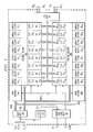
- Figure 1 is an electrical diagram, in block form, illustrating the architecture of a memory integrated circuit into which the preferred embodiment of the invention may be incorporated.
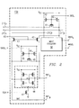
- Figure 2 is an electrical diagram, in schematic form, of one of the sense amplifiers and data drivers in the memory circuit of Figure 1.
- Figure 3 is an electrical diagram, in schematic form, of the combination of one of the data conductors and its associated dummy data conductor according to the preferred embodiment of the invention.
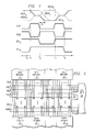
- Figure 4 is a timing diagram illustrating the operation of the preferred embodiment of the invention.
- Figure 5 is an electrical diagram, in block form, illustrating the connection of the data conductors and dummy data conductors to the data drivercir- cuits for each array block.
- Referring now to Figure 1, an example of an integrated circuit into which the preferred embodiment of the invention is implemented will be described. In this example,
memory 1 is a static random access memory (SRAM) of otherwise conventional architecture, having its memory cells inmultiple blocks 10 which are shown, in Figure 1, according to an example of their physical location in such a memory. It is contemplated that integrated circuits of other types which utilize long data conductors may also benefit from the present invention, such integrated circuits including microprocessors, logic devices, and other types of memories including read-only memories, FIFOs, DRAMs and the like. - As is conventional, memory cells in
memory 1 are arranged in rows and columns, and are selected according to an address signal received at address ter- minalsAo through An. Address terminalsAo through An are connected toaddress buffers 28, which bufferthe received address signal and communicate a portion of the address signal torow decoders column decoders 26a, 26b on bus COL.Row decoders memory array blocks 10.Column decoders 26a, 26b, in this example, select eight memory cells in the selected row to be sensed by asense amplifier 13 according to the column portion of the address. - In
memory 1 according to this example, the memory cells are grouped into sixteenarray blocks 100 through 1015. This partitioning of the memory into sixteenarray blocks 10 is particularly beneficial in low power memories, such as may be used in portable computers, as only theblock 10 in which the selected memory cells are located need be enabled during a cycle. Selection of the block may be done according to one of the row address bits (indicating upper or lower half) and to four of the column address bits (indicating one of sixteenarray blocks 10 to be selected). Further reduction in the active power may be obtained by the implementation of latched row line repeaters betweenarray blocks 10, as described in copending application S.N. 588,609, filed September 26, 1990, assigned to SGS-Thomson Microelectronics, Inc., and incorporated herein by this reference. -
Memory 1, as in the case of most modern SRAMs and DRAMs, includes some amount of dynamic operation, such as precharging and equilibration of certain nodes (e.g., bit lines) at particular points in the memory cycle. Initiation of the cycle inSRAM 1 occurs by way of address transition detection, performed by address transition detection (ATD)circuit 25.ATD circuit 25 is connected to each of the address inputs Ao through An, preferably prior to address buffers 28 (as shown), and generates a pulse on line ATD responsive to detecting a transition at any one or more of address inputsAo through An, such a pulse useful in controlling the internal operation ofmemory 1 in the conventional manner, and also in the manner to be described hereinbelow. - Other internal operational functions are controlled by timing and
control circuitry 29, which receives the signal on line ATD fromATD circuit 25, and which also receives certain external control signals such as the chip enable signal at terminal CE, and the read/write select signal at terminal R/W. Timing andcontrol circuitry 29 generates various control signals based on these inputs, for control of the various functions withinmemory 1 in the conventional manner. As shown in Figure 1, control bus CBUS is connected tosense amplifiers 13 anddata drivers 15, by which such signals as the GEQT, GEQC, SAEQ_, SCLK, ISO signals described hereinbelow are generated and communicated withinmemory 1. -
Memory 1 in this example is of the byte-wide type, and as such it has eight input/output terminals DQo through DQ7 at which output data is presented during a read operation, and at which input data is received during a write operation. Input/output circuitry 20 is connected betweendata bus 22 and terminals DQ, and includes conventional input and output buffers connected thereto. A preferred type of output buffer is described in copending application S.N. - , (Attorney's Docket No. 91-C-110), filed contemporaneously herewith, assigned to SGS-Thomson Microelectronics, Inc., and incorporated herein by this reference.
- Each of array blocks 10o through 1015 is associated with a corresponding group of
sense amplifiers 13o through 1315, as shown in Figure 1. In this exam- pie, eightindividual sense amplifiers 13 are included within each group ofsense amplifiers 13o through 1315, onesense amplifier 13 for each of the eight bits to be communicated oninternal data bus 22 from the selected one ofarray blocks 10o through 1015. Groups ofdata drivers 15o through 1515 are each associated with a corresponding group ofsense amplifiers 130 through 1315 for receiving the data signal therefrom and for drivinginternal data bus 22 therewith;individual data drivers 15 are associated withindividual sense amplifiers 13 in each group, onedata driver 15 for driving each line indata bus 22. - In this example, the memory array is also divided into halves, with
array blocks 10o through 107 in one array half and array blocks 108 through 1015 in the other half.Internal data bus 22 runs the length of the array halves, and is located therebetween as shown in Figures 1 and 5. As shown in Figure 5,data bus 22 includes data conductors DBUSo through DBUS7, each associated with an input/output terminal DQo through DQ7 (and coupled thereto via input/outputcir- cuitry 20). Each individual data conductor DBUSk is connected to acorresponding data driver 15 in each of the sixteendata driver groups 150 through 1515 of the sixteen array blocks 100 through 1015. For a read/write memory such asmemory 1, a separate input data bus can be used to communicate input data to be written to the selected memory cells, in the conventional manner. Alternatively, the input data may also be communicated alongdata bus 22, as is conventional for some memory designs. -
Data bus 22 also includes eight dummy data conductors DDBUSo through DDBUS7, each of which are also connected to a correspondingdata driver 15 in each of the sixteendata driver groups 150 through 1515 of the sixteen array blocks 100 through 1015. Dummy data conductors DDBUS0 through DDBUS7 are used for precharging ofdata bus 22, as will be described hereinbelow, and not for communication of a data state; as such, dummy data conductors DDBUS0 through DDBUS7 are not coupled to input/output circuitry 20 for communication of data to and from terminals DQ, but instead are terminated by terminations 37, as shown in Figure 5. To ensure proper precharge of data conductors DBUS, each of dummy data conductors DDBUS preferably physically resembles one of data conductors DBUS, having substantially the same length and cross- sectional area, and being formed of the same material. - In the arrangement of Figures 1 and 5, it is therefore apparent that each of the data conductors DBUS in
data bus 22 will be relatively long, running much of the length of the chip in order to connect todata drivers 15 for each of the array blocks 10. As such, the series resistance of each data bus conductor DBUS can be quite high, even when formed of metal such as aluminum, especially in high density circuits. For example, each data bus conductor DBUS can be on the order of 13,200 w long, with a cross-sectional area of on the order of 1.1 µ2; an aluminum conductor of these dimensions will have a series resistance of on the order of 550 Ω. In addition, with many (e.g., sixteen)data drivers 15 connected to each data bus conductor DBUS, as well as the input/output circuitry 20 connected thereto, the capacitance associated with a single data bus conductor DBUS can be on the order of 4 pF. The R-C load of data bus conductors DBUS can thus be quite significant, requiring on the order of 2.2 nsec to switch from rail-to-rail (5 volts) for typical on-chip drivers, and thus directly and significantly impacts the read access time of the memory. Due to the size of write drivers available in input/output circuitry 20, and also where a separate input data bus is provided, the write time may not be affected to the same degree; in addition, the duration of the write operation is generally not as critical a parameter in a high speed memory as the read access time. As will be described hereinbelow, use of dummy data conductors DDBUS according to the present invention can provide significant reduction in the access time ofmemory 1. - Referring now to Figure 2, the construction of an example of one of
sense amplifiers 13 will now be described in detail. Further detail concerning this example ofsense amplifier 13, and its operation relative to column decoder 26, is described in copending application S.N. 627,049, filed December 13, 1990, assigned to SGS-Thomson Microelectronics, Inc. and incorporated herein by this reference.Sense amplifier 13jk of Figure 2 is the sense amplifier associated witharray group 10j and input/output terminal DQk. - Of course, other sense amplifier designs may alternatively be used in connection with the present invention. One example of such an alternative design is a multiple stage sense amplifier scheme, including a level shifter stage connected to each of the differential bit lines for implementing a DC level shift thereon, followed by a combination of a current mirror and differential sense amplifier (the differential sense amplifier similar as that shown in Figure 2). Other sense amplifier configurations and implementations may similarly be used, in the alternative to that shown in Figure 2.
- In the example of Figure 2, complementary input/output lines 21Tjk, 21Cjk (T for true and C for complement) are coupled, via column decoder 26, to the bit lines of the selected memory cell in
array group 10j associated with input/output terminal DQk; in a read operation, input/output lines 21Tjk, 21Cjk communicate data from the selected memory cell, and in a write operation input/output lines 21 Tjk, 21 Cjk communicate data to the selected memory cell. Input/output lines 21Tjk, 21Cjk are each connected to the drain of a p-channel precharge transistor 42; the sources oftransistors 42 are both connected to the precharge voltage for the input/output lines 21Tjk, 21Cjk, which in this case is Vcc. Input/output lines 21 Tjk, 21Cjk are also connected to one another by p-channel equilibration transistor 41. The gates oftransistors control circuitry 22 responsive to an address transition detected byATD circuit 25, or to such other events during the cycle for which equilibration of input/output lines 21 are desired. - On the read side of
sense amplifier 13jk, input/output lines 21Tjk, 21Cjk are each connected to a p-channel pass transistor 43, each ofpass transistors 43 having its gate controlled by an isolate signal ISO. Accordingly, input/output lines 21Tjk, 21Cjk may be isolated from the read circuitry by line ISO at a high logic level, and may be connected thereto by line ISO at a low logic level. The complementary lines on the opposite side ofpass transistors 43 from input/output lines 21Tjk and 21Gjk are referred to in Figure 2 as sense nodes SNTjk and SNCjk, respectively. - Sense nodes SNTjk, SNCjk are also preferably precharged and equilibrated (in this example, to the voltage Vcc) during the appropriate portion of the cycle, as
sense amplifier 48 withinsense amplifier 13 operates in dynamic fashion, as will be described hereinbelow. P-channel precharge transistors 46 each have their source-to-drain paths connected between Vcc and sense nodes SNTjk and SNCjk, respectively.Equilibration transistor 45 is a p-channel transistor having its source-to-drain path connected between sense nodes SNTjk and SNCjk. The gates oftransistors array block 10j. - Sense amplifier48 is a conventional CMOS latch consisting of cross-coupled inverters therewithin; the inputs and outputs of the cross-coupled latches are connected to sense nodes SNTjk, SNCjk in the conventional manner. N-channel pull-
down transistor 47 has its source-to-drain path connected between the sources of the n-channel transistors insense amplifier 48 and ground, and has its gate controlled by line SCLK. - Pull-
down transistor 47 provides dynamic control ofsense amplifier 48, so that the sensing of sense nodes SNTjk, SNCjk is performed in dynamic fashion. As is well known in dynamic RAMs, the dynamic sensing in this arrangement is controlled with transistor47 initially off at the time that passtransistors 43 connect sense nodes SNTjk, SNCjk to input/output lines 21Tjk, 21Cjk, respectively; during this portion of the cycle, sense amplifier48 is presented with a small differential voltage between sense nodes SNTjk and SNCjk. After development of this small differential voltage, line SCLK is driven high, so that the sources of the pulldown transistors insense amplifier 48 are pulled to ground. This causessense amplifier 48 to develop a large differential signal on sense nodes SNTjk and SNCjk, and latch the sensed state thereof. - As will be apparent from the description hereinbelow, each
sense amplifiers 13jk associated with the same data conductor DBUSk are coupled to one another in essentially wired-OR fashion. Accordingly, the control signals ISO, SAEQ_ , and SCLKwhich are presented to the read side ofsense amplifier 13jk are preferably generated by column decoder 26 in conjunction withtiming control circuitry 29. Such generation of these control signals provides that the ones ofsense amplifier 13jk associated with unselected array blocks 10 are not enabled (by lines ISO maintained high, and lines SAEQ_ and SCLK maintained low) so as to maintain their sense nodes SNTjk and SNCjk equilibrated and precharged to Vcc, preventing bus conflict ondata bus 22. - On the write side of
sense amplifier 13jk, writecircuitry 50jk receives input data from data conductor DBUSk associated therewith, and a control signal on line WRSEL from timing andcontrol circuitry 29. In write operations, writecircuitry 50jk presents the data state of data conductor DBUSk in complementary fashion on input/output lines 21Tjk, 21Cjk in the conventional fashion. The above-referenced copending application S.N. 627,049 describes a preferred example ofwrite circuitry 50jk, in further detail. - Referring now to Figure 3, the construction and operation of one of
data drivers 15 according to the preferred embodiment of the invention will now be described in detail.Data driver 15jk of Figure 3 is associated with input/output terminal DQk and witharray block 10j and accordingly receives, as inputs, nodes SNTjk and SNCjk fromsense amplifier 13jk of Figure2. - Nodes SNTjk and SNCjk are received at inputs of
tristate data driver 15jk. According to this embodiment of the invention, and as will become apparent hereinbelow, data conductors DBUS and dummy data conductors DDBUS must each be driven by tristate drivers, in order to enable their precharging by way of charge sharing with one another. In addition, sincemultiple data drivers 15 drive the same data conductors DBUS (and dummy data conductors DDBUS), each ofdata drivers 15 must have a high-impedance state to avoid bus contention problems. In prior memory configurations, this is generally accomplished by merely turning off the sense amplifiers. However, sincesense amplifiers 13 in this example precharge their output nodes SNT, SNC high (as is the case in many memory circuits), this state does not necessarily prevent the active driving of data conductors DBUS. - Other prior schemes, in which sense amplifier outputs are precharged to the same voltage, have included an enable signal for controlling tristate data drivers. In these prior schemes, however, an additional signal line must be provided for each data driver, as well as the necessary circuitry for generating this additional signal and also a relatively complex data driver capable of responding to the additional signal. Still other conventional schemes included a series pass gate between the sense amplifier and the internal data bus, such a pass gate adding its propagation delay time in the critical read path, and thus being undesirable.
-
Data driver 15jk according to the preferred embodiment of the invention provides tristate capability in a simple and effective manner.Driver 15jk includes two push-pull driver circuits therein, for driving complementary nodes GDTjk and GDCjk, respectively, which in turn are connected to data conductor DBUSk and dummy data conductor DDBUSk, respectively. These push-pull drivers each include p-channel pull-up transistor 56 and n-channel pull-down transistor 58, having their source/drain paths connected in series between Vcc and ground; the output of each of the drivers is, in the conventional sense, at the common drain of transistors 56 and 58. In this example, the drains oftransistors transistors 56C, 58C at node GDCjk are connected to dummy data conductor DDBUSk. Referring back to Figures 1 and 5, similar nodes GDT, GDC in the other fifteendata drivers 15 are similarly connected to data conductor DBUSk and dummy data conductor DDBUSk, thus necessitating the ability ofdrivers 15 to have a high- impedance output state. - Node SNCjk is connected to the gate of pull-up
transistor 56T after inversion by twoinverters 53, and is connected to the gate of pull-down transistor 58C after inversion by one ofinverters 53. Conversely, node SNTjk is connected directly to the gate of pull-uptransistor 56C via twoinverters 55, and to the gate of pull-down transistor 58T after inversion by one ofinverters 55. The connection of twoinverters sense amplifier 13jk. - In operation, when
sense amplifier 13jk is on, and senses a logic "one" state in the selected memory cell, node SNTjk will be high and node SNCjk will be low. Accordingly, transistors 58Tand 56Cwill both be off, andtransistors 56T and 58C will both be on, driving node GDTjk to a high logic level and driving node GDCjk to a low level. Conversely, whensense amplifier 13jk senses a logic "zero" state, node SNTjk will be low and node SNCjk will be high; this turns ontransistors transistors 56T, 58C, and thus drives node GDTjk low and node GDCjk high. - As described hereinabove,
sense amplifier 13jk is turned off when itsarray block 10j is not selected (or during a write operation). In this embodiment,sense amplifier 13jk drives both of its nodes SNTjk, SNCjk high when disabled, by operation oftransistors transistors transistors 56T, 58C, and a high logic level on node SNTjk turns offtransistors sense amplifier 13jk being turned off, placing nodes GDTjk and GDCjk at their output in a high-impedance state. This tristate condition is therefore obtained without requiring the generation and communication of an additional signal, but is accomplished as a response to the precharged condition ofsense amplifier 13jk. Accordingly, to enable precharge and equilibration of data conductors DBUS and dummy data conductors DDBUS,driver 15jk is placed in a high impedance state during precharge and equilibration, as signal SAEQ is at a low logic level during this time (placing both nodes SNTjk, SNCjk high at that time). - Data bus conductors DDBUS and dummy data bus conductors DDBUS can all biased to known complementary voltages, by way of
transistors transistors transistors channel transistor 61 n, which has its source connected to ground and its gate connected to line GFN; dummy data bus conductor DDBUSk is connected to the drain of p-channel transistor 61 p, which has its source biased to Vcc and its gate connected to line GFN viainverter 63. Accordingly, when line GFN when is at high logic level, data conductor DBUSk is biased to ground, and dummy data conductor DDBUSk are biased to Vcc; conversely, when line GFN is low,transistors memory 1 is deselected, so that a complementary relationship between each data conductor DBUS and its dummy data bus conductor DDBUS is maintained at all times. -
Memory 1 further includes self-biasingcircuits 54T, 54C, each connected to data conductor DBUSk and dummy data conductor DDBUSk, respectively, to maintain these lines from floating during equilibration and precharge. A single self-biasingcircuits 54T, 54C may be implemented for each data conductor DBUSk and dummy data conductor DDBUSk inmemory 1, or alternatively multiple self- biasingcircuits 54T, 54C may be used for each data conductor DBUSk and dummy data conductor DDBUSk, depending upon the drive required to maintain the precharged state thereof. As is well known, noise can capacitively couple to floating nodes in integrated circuits, such that the potential of such nodes can rise or fall to any potential, especially during long equilibration periods such as can occur if the addresses received bymemory 1 are unstable. As will be apparent hereinbelow, floating of data conductors DBUS to a voltage significantly different from the preferred mid-level voltage can push out the access time of the memory if the next data state to be driven is the opposite from that to which one or more of data conductors DBUS floated. - Self-biasing
circuit 54T includes p-channel transistors channel transistors transistors - The gate of p-
channel transistor 66 is connected to line GEQC, which is a precharge signal active at a low logic level, and the gate of n-channel transistor68 is connected to line GEQT, which is a precharge signal active at a high logic level. Lines GEQT and GEQC (which are the logical complements of one another), are generated by timing andcontrol circuitry 29 as high and low logic level pulses, respectively, which control the initiation and duration of the precharge of data conductors DBUS. In this embodiment of the invention, lines GEQT, GEQC are derived by timing andcontrol circuitry 29 from the pulse on line ATD generated byATD circuit 25 responsive to detection of a transition at one or more of address terminals Ao through An, and communicated along control bus CBUS. Derivation of the precharge signals from address transition detection enables precharging of data conductors DBUS at the appropriate early portion of the cycle, since a new memory cycle in an SRAM such asmemory 1 begins with receipt of a new address. Such precharge at the beginning of the cycle, rather than at the end, is of course preferred for SRAMs since the duration of the cycle is indeterminate. - Self-biasing circuit 54C is similarly constructed, with p-
channel transistors 65p, 67 having their source/drain paths connected in series between dummy data bus conductor DDBUSk and Vcc, and with n-channel transistors transistors 65p, 65n are connected to dummy data bus conductor DDBUSk, and the gates oftransistors - In operation, self-biasing
circuits 54T, 54C are enabled only during the precharge and equilibration operation, when line GEQT is high and line GEQC is low. When enabled, the voltage at data bus conductor DBUSk (forthe case of self-biasingcircuit 54T) will determine the state oftransistors 65p or 65n. As noted hereinabove and as will be described hereinbelow, data conductor DBUSk is not actively driven during precharge. Accordingly, if noise couples to data conductor DBUSk which causes its voltage to rise,transistor 64n will tend to turn on harder, and discharge data conductor DBUSk until such time as its voltage turns offtransistor 64n (or turns it on to a lesser degree than transistor64p is turned on). Self-biasing circuit 54C operates in the same manner relative to dummy data conductor DDBUSk. Accordingly, self-biasingcircuits 54T, 54C keep data conductors DBUS and dummy data conductors DDBUS from floating during precharge, particularly during long precharge and equilibration operations. - The terminal end of data conductor DBUSk is received by input/
output circuitry 20, specifically at the gates of p-channel pull-up transistor 72p and n-channel pull-down transistor 72n inoutput stage 80. The source/drain paths oftransistors 72p, 72n are connected in series, between Vcc and ground, with the source/drain paths oftransistors channel transistor 74 is connected to line GEQT, and the gate of n-channel transistor 76 is connected to line GEQC, and their drains are connected together.Latch 78, consisting of cross-coupled inverters, has its input connected to the drains oftransistors latch 78, node Qk is forwarded to the output buffers ofmemory 1 for presentation thereat. - In operation, during precharge and equilibration (line GEQT high and line GEQC low), the state of data conductor DBUS is isolated from affecting node Qk, as
transistors transistors output stage 80 operates as a conventional CMOS inverter. Sincetransistors output stage 80 are turned off during the precharge and equilibration period,output stage 80 is disabled from responding to the state of data conductor DBUSk. This allows data conductor DBUSk to be safely precharged to a voltage near the trip point ofoutput stage 80, without resulting in oscillations of the output circuitry as would otherwise occur ifoutput stage 80 remained enabled during precharge. - It is preferred that self-biasing
circuit 54T (and self- biasing circuit 54C, for symmetry) be constructed in such a manner that its bias point is near the trip point ofoutput stage 80 driven by data conductor DBUS. As such, the push-pull construction of self-biasingcircuit 54T matches the construction ofoutput stage 80. In order to minimize the current drawn through self- biasingcircuits 54T, 54C, it is preferred that the sizes of the transistors therein be scaled from those inoutput stage 80. For example, the channel widths of the transistors in self-biasingcircuits 54T, 54C are preferably on the order of one-fourth of the transistors inoutput stage 80; the channel lengths in self-biasingcircuits 54T, 54C are preferably longer, for example by a factor of three, than inoutput stage 80. The bias current provided by self-biasingcircuits 54T, 54C is therefore quite small, but is sufficient to keep data conductors DBUS from floating to a voltage significantly different from its precharged level. - It is contemplated that self-biasing
circuits 54T, 54C may also be beneficial when implemented in other data bus arrangements, for example a differential data bus where each bit of data is communicated by a differential ( or complementary ) signal carried on a pair of data bus lines. The advantages of maintaining the precharged level on differential conductors as described hereinabove may thus be obtained in these arrangements, as well. -
Equilibration transistor 70 has its source/drain path connected between data conductor DBUSk and dummy data conductor DDBUSk, and has its gate connected to line GEQT (transistor 70 being n-channel).Transistor 70 is therefore turned on during precharge (line GEQT high), and will effect the precharging of data conductor DBUS by way of charge sharing, as will be described hereinbelow. Alternatively, a p-channel transistor with its gate controlled by line GEQC may be used in place of, or in parallel with, n-channel equilibration transistor 70. In addition, it may be preferable in some cases to providemultiple transistors 70 for each data conductor DBUSk and dummy data conductor DDBUSk, for example onetransistor 70 at each end thereof; of course, depending upon the size oftransistor 70, a single placement may be sufficient. - As illustrated in Figure 5, dummy data conductors DDBUS are terminated by terminations 37. Terminations 37 provide a load to dummy data conductor DDBUS which matches that presented by
output stage 80 to data conductors DBUS. In the example of Figure 3, termination 37k includes p-channel transistor 81 p which has its source and drain connected together to Vcc, and n-channel transistor 81 n which has its source and drain connected together to ground; the gates oftransistors output stage 80 presents to data conductor DBUSk. - Referring now to Figure 4, the operation of the preferred embodiment of the invention will now be described in detail. At time to in this example, data conductor DBUSk is at a high level and dummy data conductor DDBUSk is at a low level, due to the complementary operation of
tristate driver 15jk as a result of node SNTjk at a high level and node SNCjk at a low level. Also at time to, since the access of the selected memory cell has been active for some time, precharge lines GEQT and GEQC are low and high, respectively. - The precharge and equilibration operation begins at time t1, which is a specified time after the beginning of the next cycle; as noted hereinabove, a new cycle in
memory 1 can be initiated by a transition at one or more of address terminals Ao through An, at the end of a write operation, or upon receipt of a chip enable signal. Responsive to detection of this transition, at time t1, line GEQT is driven to a high level, line GEQC is driven low; also at this time,sense amplifier 13jk is turned off by way of lines SAEQ and SCLK, so that node SNCjk goes to a logic high level. With both nodes SNTjk and SNCjk high,tristate driver 15jk enters a high impedance state. - Prior to time t1, data conductor DBUSk and dummy data conductor DDBUSk (since all
other sense amplifiers 13 andtristate drivers 15 are in a high impedance state, having not been selected in this cycle) are at high and low logic levels, respectively. As line GEQT goes to a high level at time t1,transistor 70 turns on, connecting data conductor DBUSk to dummy data conductor DDBUSk. Sincetristate driver 15jk enters its high impedance state at this time and no longer actively drives either data conductor DBUSk and dummy data conductor DDBUSk,transistor 70 initiates charge sharing between data conductor DBUSk and dummy data conductor DDBUSk. Data conductor DBUSk and dummy data conductor DDBUSk thus discharge and charge, respectively, to a common potential near the mid-level between high and low logic levels. Precharge of data conductor DBUSk is then complete. - Also during this time,
output stage 80 is disabled from responding to the precharged state of data conductor DBUSk, astransistors - For purposes of clarity, the duration of precharge and equilibration between times t1 and t2, as illustrated in Figure 4, is relatively short. As such, the voltage of data conductor DBUSk and dummy data conductor DDBUSk is not likely to significantly drift from its precharged level as a result of capacitively coupled noise. However, in
memory 1 as in many SRAM and DRAM memory devices, the precharge and equilibration period can be quite long, for example on the order of microseconds. In an SRAM device where precharge and equilibration are triggered by address transition detection, such asmemory 1, a long precharge and equilibration period can result from unstable, or high frequency, address signals applied tomemory 1. In clocked circuits, such as FIFOs, DRAMs, embedded memories in microprocessors, microprocessors themselves, and the like, a low frequency or long duty cycle clock signal will cause a long precharge and equilibration period. - Self-biasing
circuits 54T, 54C prevent data conductors DBUS and dummy data conductors DDBUS from drifting far from their precharged voltage, even during long precharge and equilibration periods. As noted hereinabove relative to Figure 3, if data conductor DBUSk receives noise which causes it to drift upward,transistor 64n (andtransistor 65n, due totransistor 70 being on) will turn on harder, discharging data conductor DBUSk (and dummy data conductor DDBUSk) to ground;transistors 64p, 65p operate similarly if data conductor DBUSk and dummy data conductor DDBUSk drift low. As a result, the precharged level of data bus conductors DBUS indata bus 22 ofmemory 1 is maintained, and is maintained near the trip point ofoutput stage 80, in the preferred embodiment of the invention, even over long precharge and equilibration periods. - Referring back to Figure 4, the next read access operation begins at time t2 with lines GEQT, GEQC returning low and high, respectively. For clarity of explanation, it is presumed that the next access is also from
array block 10j; the operation of data conductor DBUSk will be similar, however, if adifferent array block 10 were selected. With the end of precharge at time t2,sense amplifier 13jk is again enabled. In this example, the next data state to be presented is a "0", and accordingly node SNTjk is driven low bysense amplifier 13jk at the end of the precharge and equilibration period. Self-biasingcircuits 54T, 54C are disabled by lines GEQT, GEQC returning low and high, respectively, and thereforedata driver 15jk begins driving data conductor DBUSk low from the precharged level (and also begins driving dummy data conductor DDBUSk high). - Also at this time, upon the return of lines GEQT, GEQC low and high, respectively,
output stage 80 is again enabled to receive the data state on data conductor DBUSk. Since the construction ofoutput stage 80 and self-biasingcircuit 54T is similar, except for transistor scaling, the precharged voltage to which data conductor DBUSk is held is quite close to the trip voltage ofoutput stage 80. Accordingly, input/output circuitry 20 can respond very quickly to the discharging (in this case) of data conductor DBUSk from its midlevel voltage, in this case immediately after time t2. This provides savings in the access time of memory I from that in prior configurations where data conductors in data buses would, in the worst case, have to be switched from rail-to-rail. Figure 4 illustrates the rail-to-rail discharging of data conductor DBUSk' in such a prior arrangement. Assuming that the new access begins at the same time (i.e., time t2), prior data conductor DBUSk' does not reach the trip point ofoutput stage 80 until well after time t2, due to the R-C load presented thereby to its driver. The access time savings provided by the present invention is illustrated in Figure 4 by Δt, which in modern high speed SRAMs can be on the order of 1.5 to 2.0 nsec, and thus on the order of 10% of the overall access time ofmemory 1. - During the active period between times t2 and t3, dummy data conductor DBUSk is driven by
tristate driver 15jk to the opposite data state (in this case a "1") from that of data conductor DBUSk. Termination 37k adds a load to dummy data conductor DDBUSk similar to that ofoutput stage 80, and as such the switching of dummy data conductor DBUSk matches, in a complementary fashion, the switching of data conductor DBUSk. As a result, the state of dummy data conductor DDBUSk is complementary to that of data conductor DDBUSk at all times during the active period, even during the transient switching time. The provision of the matching load by termination 37k thus allows the next precharge operation to begin at any time, as may occur in circuits such asSRAM memory 1, ensuring that charge sharing will precharge data conductor DBUSk to the proper midlevel voltage. - The opposite transition of data conductor DBUSk is illustrated in Figure 4, beginning with precharge and equilibration at time t3. In this case, as lines GEQT, GEQC are driven high and low, respectively node SNTjk is pulled high to place
tristate driver 15jk in its high impedance state,transistor 70 is turned on to equilibrate data conductor DBUSk and dummy data conductor DDBUSk which are thus precharged, by way of charge sharing, to a midlevel voltage. Self-biasingcircuits 54T, 54C operate as before to maintain this precharged level on data conductor DDBUSk. Beginning at time t4, the next access begins with lines GEQT, GEQC returning low and high, respectively, at which time the new high level data state is presented by node SNCjk driven low bysense amplifier 13jk. - The present invention thus provides the significant advantage of improved access times, by reducing the time required to switch high capacitance internal data buses. The instantaneous dynamic current drawn by
memory 1 is also reduced, as the switching voltage of the data conductors in the internal data bus is reduced by approximately one-half. These advantages are achieved by way of charge sharing, thus not requiring generation of a precharge voltage driver and the circuitry necessary to apply the generated precharge voltage; in addition, self-biasing circuits are provided to prevent floating of the data bus to undesired voltages, particularly in long precharge and equilibration periods, as such floating could slow the access time in the next cycle. Furthermore, the precharging of the data bus is facilitated by a tristate data driver which enters the high impedance mode by operation of the sense amplifier, without requiring an additional timing and control signal to be applied thereto. - While the invention has been described herein relative to its preferred embodiment, it is of course contemplated that modifications of, and alternatives to, this embodiment, such modifications and alternatives obtaining the advantages and benefits of this invention, will be apparent to those of ordinary skill in the art having reference to this specification and its drawings. It is contemplated that such modifications and alternatives are within the scope of this invention as subsequently claimed herein.
Claims (34)
Applications Claiming Priority (4)
| Application Number | Priority Date | Filing Date | Title |
|---|---|---|---|
| US809733 | 1991-12-17 | ||
| US07/809,733 US5257226A (en) | 1991-12-17 | 1991-12-17 | Integrated circuit with self-biased differential data lines |
| US07/809,735 US5295104A (en) | 1991-12-17 | 1991-12-17 | Integrated circuit with precharged internal data bus |
| US809735 | 1991-12-17 |
Publications (3)
| Publication Number | Publication Date |
|---|---|
| EP0547892A2 true EP0547892A2 (en) | 1993-06-23 |
| EP0547892A3 EP0547892A3 (en) | 1994-05-18 |
| EP0547892B1 EP0547892B1 (en) | 1998-10-28 |
Family
ID=27123252
Family Applications (1)
| Application Number | Title | Priority Date | Filing Date |
|---|---|---|---|
| EP92311514A Expired - Lifetime EP0547892B1 (en) | 1991-12-17 | 1992-12-16 | An integrated circuit with self-biased differential data lines |
Country Status (3)
| Country | Link |
|---|---|
| EP (1) | EP0547892B1 (en) |
| JP (1) | JPH05274884A (en) |
| DE (1) | DE69227436T2 (en) |
Cited By (6)
| Publication number | Priority date | Publication date | Assignee | Title |
|---|---|---|---|---|
| EP0632389A1 (en) * | 1993-06-30 | 1995-01-04 | STMicroelectronics, Inc. | Cache tag memory |
| EP0690430A3 (en) * | 1994-06-02 | 1996-07-03 | Accelerix Ltd | Single chip frame buffer and graphics accelerator |
| GB2302973A (en) * | 1995-06-30 | 1997-02-05 | Hyundai Electronics Ind | Data bus drive circuit for a semiconductor memory |
| US6041010A (en) * | 1994-06-20 | 2000-03-21 | Neomagic Corporation | Graphics controller integrated circuit without memory interface pins and associated power dissipation |
| FR2787212A1 (en) * | 1998-12-10 | 2000-06-16 | Fujitsu Ltd | CIRCUIT FOR RESETTING A PAIR OF DATA BUSES OF A SEMICONDUCTOR MEMORY DEVICE |
| WO2004105245A2 (en) * | 2003-05-20 | 2004-12-02 | Cray Inc. | Half-swing line precharge method and apparatus |
Families Citing this family (2)
| Publication number | Priority date | Publication date | Assignee | Title |
|---|---|---|---|---|
| KR0167235B1 (en) * | 1995-03-28 | 1999-02-01 | 문정환 | Data transferring apparatus for memory |
| KR0167298B1 (en) * | 1995-12-20 | 1999-01-15 | 문정환 | Fast access memory device |
Citations (2)
| Publication number | Priority date | Publication date | Assignee | Title |
|---|---|---|---|---|
| EP0408032A2 (en) * | 1989-07-12 | 1991-01-16 | Kabushiki Kaisha Toshiba | Data output control circuit for semiconductor storage device |
| US5062082A (en) * | 1990-09-04 | 1991-10-29 | Samsung Electronics Co., Ltd. | Semiconductor memory device with delay in address predecoder circuit independent from ATD |
-
1992
- 1992-12-16 DE DE1992627436 patent/DE69227436T2/en not_active Expired - Fee Related
- 1992-12-16 EP EP92311514A patent/EP0547892B1/en not_active Expired - Lifetime
- 1992-12-17 JP JP4336495A patent/JPH05274884A/en active Pending
Patent Citations (2)
| Publication number | Priority date | Publication date | Assignee | Title |
|---|---|---|---|---|
| EP0408032A2 (en) * | 1989-07-12 | 1991-01-16 | Kabushiki Kaisha Toshiba | Data output control circuit for semiconductor storage device |
| US5062082A (en) * | 1990-09-04 | 1991-10-29 | Samsung Electronics Co., Ltd. | Semiconductor memory device with delay in address predecoder circuit independent from ATD |
Non-Patent Citations (2)
| Title |
|---|
| IEEE JOURNAL OF SOLID-STATE CIRCUITS, vol.SC-21, no.5, October 1986, NEW YORK US pages 686 - 691 KAYANO ET AL '25-ns 256Kx1/64Kx4 CMOS SRAMs' * |
| TRANSACTIONS OF THE INSTITUTE OF ELECTRONICS, INFORMATION AND COMMUNICATION ENGINEERS OF JAPAN, vol.E74, no.4, April 1991, TOKYO JP pages 799 - 810, XP000241300 NAKAGOME ET AL 'Reviews and Prospects of DRAM Technology' * |
Cited By (16)
| Publication number | Priority date | Publication date | Assignee | Title |
|---|---|---|---|---|
| EP0632389A1 (en) * | 1993-06-30 | 1995-01-04 | STMicroelectronics, Inc. | Cache tag memory |
| USRE37944E1 (en) | 1994-06-02 | 2002-12-31 | 3612821 Canada Inc. | Single chip frame buffer and graphics accelerator |
| EP0690430A3 (en) * | 1994-06-02 | 1996-07-03 | Accelerix Ltd | Single chip frame buffer and graphics accelerator |
| USRE44589E1 (en) | 1994-06-02 | 2013-11-12 | Mosaid Technologies Incorporated | Single chip frame buffer and graphics accelerator |
| US5694143A (en) * | 1994-06-02 | 1997-12-02 | Accelerix Limited | Single chip frame buffer and graphics accelerator |
| USRE41565E1 (en) | 1994-06-02 | 2010-08-24 | Mosaid Technologies Incorporated | Single chip frame buffer and graphics accelerator |
| USRE40326E1 (en) | 1994-06-02 | 2008-05-20 | Mosaid Technologies Incorporated | Single chip frame buffer and graphics accelerator |
| US6920077B2 (en) | 1994-06-20 | 2005-07-19 | Neomagic Corporation | Graphics controller integrated circuit without memory interface |
| US6771532B2 (en) | 1994-06-20 | 2004-08-03 | Neomagic Corporation | Graphics controller integrated circuit without memory interface |
| US6041010A (en) * | 1994-06-20 | 2000-03-21 | Neomagic Corporation | Graphics controller integrated circuit without memory interface pins and associated power dissipation |
| GB2302973B (en) * | 1995-06-30 | 2000-03-01 | Hyundai Electronics Ind | Data bus drive circuit for semiconductor memory device |
| GB2302973A (en) * | 1995-06-30 | 1997-02-05 | Hyundai Electronics Ind | Data bus drive circuit for a semiconductor memory |
| US6462997B2 (en) | 1998-12-10 | 2002-10-08 | Fujitsu Limited | Circuit for resetting a pair of data buses of a semiconductor memory device |
| FR2787212A1 (en) * | 1998-12-10 | 2000-06-16 | Fujitsu Ltd | CIRCUIT FOR RESETTING A PAIR OF DATA BUSES OF A SEMICONDUCTOR MEMORY DEVICE |
| WO2004105245A2 (en) * | 2003-05-20 | 2004-12-02 | Cray Inc. | Half-swing line precharge method and apparatus |
| WO2004105245A3 (en) * | 2003-05-20 | 2005-05-06 | Cray Inc | Half-swing line precharge method and apparatus |
Also Published As
| Publication number | Publication date |
|---|---|
| JPH05274884A (en) | 1993-10-22 |
| EP0547892B1 (en) | 1998-10-28 |
| EP0547892A3 (en) | 1994-05-18 |
| DE69227436D1 (en) | 1998-12-03 |
| DE69227436T2 (en) | 1999-04-15 |
Similar Documents
| Publication | Publication Date | Title |
|---|---|---|
| US6172918B1 (en) | Semiconductor memory device allowing high-speed operation of internal data buses | |
| US4355377A (en) | Asynchronously equillibrated and pre-charged static ram | |
| US6522163B1 (en) | Apparatus and method for coupling a first node to a second node using switches which are selectively clocked for fast switching times | |
| US5267197A (en) | Read/write memory having an improved write driver | |
| US5305268A (en) | Semiconductor memory with column equilibrate on change of data during a write cycle | |
| KR970004416B1 (en) | Random-access memory and its read and write circuit as well as read and write method of data packet | |
| US4680735A (en) | Semiconductor memory device | |
| JP4191278B2 (en) | Memory device with fast write recovery and associated write recovery method | |
| US5539691A (en) | Semiconductor memory device and method for reading and writing data therein | |
| US5748556A (en) | Tristatable driver for internal data bus lines | |
| US6023437A (en) | Semiconductor memory device capable of reducing a precharge time | |
| US5295104A (en) | Integrated circuit with precharged internal data bus | |
| US5257226A (en) | Integrated circuit with self-biased differential data lines | |
| EP0547892B1 (en) | An integrated circuit with self-biased differential data lines | |
| US4831590A (en) | Semiconductor memory including an output latch having hysteresis characteristics | |
| US5646893A (en) | Segmented read line circuit particularly useful for multi-port storage arrays | |
| JPH04184785A (en) | Semiconductor memory | |
| KR0155986B1 (en) | Semiconductor memory device | |
| US6067264A (en) | High speed semiconductor memory device | |
| US5384504A (en) | Sense amplifier powered from bit lines and having regeneratively cross-coupling means | |
| US5515315A (en) | Dynamic random access memory | |
| US5646892A (en) | Data reading circuit | |
| US6127878A (en) | Driver circuit with negative lower power rail | |
| GB2338808A (en) | Semiconductor memory | |
| WO1985002314A2 (en) | Semiconductor memory |
Legal Events
| Date | Code | Title | Description |
|---|---|---|---|
| PUAI | Public reference made under article 153(3) epc to a published international application that has entered the european phase |
Free format text: ORIGINAL CODE: 0009012 |
|
| AK | Designated contracting states |
Kind code of ref document: A2 Designated state(s): DE FR GB IT |
|
| PUAL | Search report despatched |
Free format text: ORIGINAL CODE: 0009013 |
|
| AK | Designated contracting states |
Kind code of ref document: A3 Designated state(s): DE FR GB IT |
|
| 17P | Request for examination filed |
Effective date: 19941111 |
|
| 17Q | First examination report despatched |
Effective date: 19950901 |
|
| GRAG | Despatch of communication of intention to grant |
Free format text: ORIGINAL CODE: EPIDOS AGRA |
|
| GRAG | Despatch of communication of intention to grant |
Free format text: ORIGINAL CODE: EPIDOS AGRA |
|
| GRAH | Despatch of communication of intention to grant a patent |
Free format text: ORIGINAL CODE: EPIDOS IGRA |
|
| GRAH | Despatch of communication of intention to grant a patent |
Free format text: ORIGINAL CODE: EPIDOS IGRA |
|
| GRAA | (expected) grant |
Free format text: ORIGINAL CODE: 0009210 |
|
| AK | Designated contracting states |
Kind code of ref document: B1 Designated state(s): DE FR GB IT |
|
| REF | Corresponds to: |
Ref document number: 69227436 Country of ref document: DE Date of ref document: 19981203 |
|
| ET | Fr: translation filed | ||
| RAP4 | Party data changed (patent owner data changed or rights of a patent transferred) |
Owner name: STMICROELECTRONICS, INC. |
|
| PLBE | No opposition filed within time limit |
Free format text: ORIGINAL CODE: 0009261 |
|
| STAA | Information on the status of an ep patent application or granted ep patent |
Free format text: STATUS: NO OPPOSITION FILED WITHIN TIME LIMIT |
|
| PG25 | Lapsed in a contracting state [announced via postgrant information from national office to epo] |
Ref country code: DE Free format text: LAPSE BECAUSE OF NON-PAYMENT OF DUE FEES Effective date: 19991001 |
|
| 26N | No opposition filed | ||
| REG | Reference to a national code |
Ref country code: GB Ref legal event code: IF02 |
|
| PGFP | Annual fee paid to national office [announced via postgrant information from national office to epo] |
Ref country code: GB Payment date: 20031210 Year of fee payment: 12 |
|
| PGFP | Annual fee paid to national office [announced via postgrant information from national office to epo] |
Ref country code: FR Payment date: 20041208 Year of fee payment: 13 |
|
| PG25 | Lapsed in a contracting state [announced via postgrant information from national office to epo] |
Ref country code: GB Free format text: LAPSE BECAUSE OF NON-PAYMENT OF DUE FEES Effective date: 20041216 |
|
| GBPC | Gb: european patent ceased through non-payment of renewal fee |
Effective date: 20041216 |
|
| PG25 | Lapsed in a contracting state [announced via postgrant information from national office to epo] |
Ref country code: IT Free format text: LAPSE BECAUSE OF NON-PAYMENT OF DUE FEES Effective date: 20051216 |
|
| PG25 | Lapsed in a contracting state [announced via postgrant information from national office to epo] |
Ref country code: FR Free format text: LAPSE BECAUSE OF NON-PAYMENT OF DUE FEES Effective date: 20060831 |
|
| REG | Reference to a national code |
Ref country code: FR Ref legal event code: ST Effective date: 20060831 |